

Page 1
UTP Encoder/Decoder Set
NM-UTPSET
The NetMedia UTP Video Encoder and Decoder modules allow popular 12V DC cameras to use Unshielded Twisted Pair
(UTP) cable, such as CAT5, for both power and video. There is no need to run multiple cables to the camera location! The
modules support cable distances up to 1000 feet. To view the video, use a security monitor or the composite RCA Video
Input jack of a television.
Product Includes:
1. NetMedia UTP Video Encoder module.
2. NetMedia UTP Video Decoder module.
3. 24V DC 200mA Power Transformer.
3. Power Extension Cable and two RCA Video Cables.
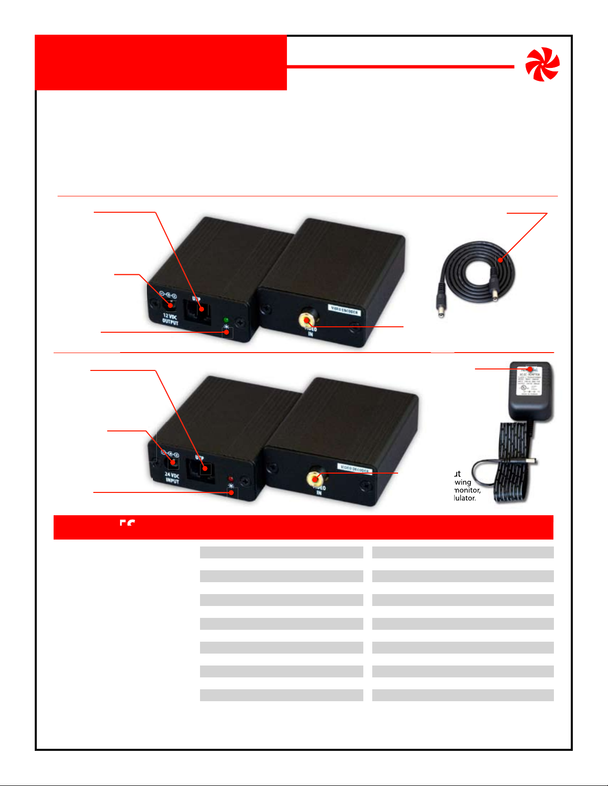
Video and Power Transmission Device
UTP Jack
Connects to Decoder UTP
Jack via straight-through
wired UTP cable (T-568A).
Power Output
Provides 12V DC 150mA
power for camera.
Green LED
Indicates Power.
UTP Jack
Connects to Encoder UTP
Jack via straight-through
wired UTP cable (T-568A).
Power Input
Uses 24V DC from included
Power Transformer.
Red LED
Indicates Power.
UTP Video Encoder
UTP Video Decoder
Power Extension Cable
Connects to 12V DC power
input of camera.
(Front) (Back)
RCA Video In
Connects to video
output of camera.
Power Transformer
Connects to 24V DC Power
Input of Decoder and AC outlet.
(Front) (Back)
RCA Video Out
Connects to viewing
device such as monitor,
DVR, TV, or modulator.
FEATURES
One Wire Video™ Installation
Supports popular color and B/W cameras
Provides remote 12V DC 150mA power
Uses one inexpensive UTP cable
Uses pre-existing CAT5 or better cable
Supports up to 1000 ft with color and B/W
Supports industry standard wiring schemes
Supports standard RJ-45 plugs
Sturdy aluminum boxes
Includes power supply
1 year limited warranty
NetMedia, Inc., 10940 N. Stallard Place, Tucson, Arizona 85737 (520) 544-4567 Fax: (520) 544-0800 Email: sales@netmedia.com www.netmedia.com
SPECIFICATIONS
Input/Output Video Connector:
Input/Output Video Signal:
Encoder/Decoder Video Connector:
Encoder/Decoder Video Signal:
Encoder/Decoder Cable Type:
Encoder/Decoder Cable Distance Range:
UTP Encoder Size:
UTP Encoder Weight:
UTP Encoder Power Output:
UTP Encoder Power Connector:
UTP Decoder Size:
UTP Decoder Weight:
UTP Decoder Power Input:
UTP Decoder Power Connector:
Female RCA
Composite
Female RJ-45 jack
Proprietary
UTP: CAT5 or better
Up to 1000’
3.2” long, 2.2” wide, 0.9” thick
3 oz.
12V DC, 150mA
5.5mm OD, 2.1mm ID, center positive
3.2” long, 2.2” wide, 0.9” thick
3 oz.
24V DC, 200mA
5.5mm OD, 2.1mm ID, center positive
(subject to change without notice)
MAN-UTPSET REV0703A
NM-UTPSET
Page 2
NM-UTPSET
Camera
Camera
Camera
Installation Procedures:
1. Connect a UTP cable (CAT5 or better) to the UTP jacks of the Video Encoder and Decoder. Each Encoder/Decoder pair
needs a dedicated point-to-point wiring circuit. If attaching your own plugs, wire them for straight-through connections: pin1 to pin1, pin2 to pin2; pin3 to pin3, etc. For standardization, you should also follow the T-568A color specification but it will not affect the modules’ function. Do not connect the UTP cable to computer networks or other
UTP video systems! Doing so could damage this product and/or the other attached devices!
2. Connect a video cable from the camera to the Encoder’s RCA Video In jack. Simple adapters, such as RCA to BNC, may
be used where appropriate.
3. Connect the Power Extension Cable from the Encoder’s Power Output Connector to the camera’s 12V DC power input.
If the camera requires more than 150mA or if it does not use 12V DC then it cannot use the Encoder’s power output.
4. Connect a video cable from the viewing device (monitor, Quad, DVR, modulator, etc.) to the Decoder’s RCA Video Out
jack using appropriate adapters where necessary.
5. Connect the 24V DC 200mA Power Transformer from an AC outlet to the Decoder’s Power Input Connector.
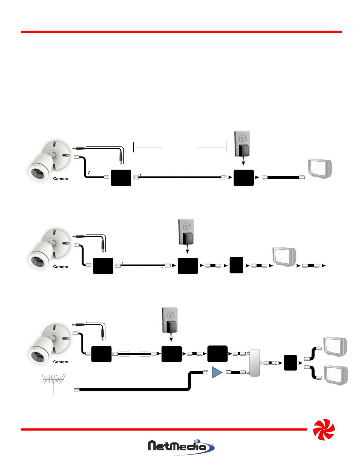
Up to 1000 Feet
24 VDC
INPUT
Video Cable
Monitor
Television
Camera
Video Cable
12 VDC
OUTPUT
UTP Cable
POWER
VIDEO
UTP Video Decoder Module UTP Video Encoder Module
Figure 1 - Connecting the modules to a security monitor or standard television. Use the TV’s composite RCA Video
In jack and view through its video or line input. The picture will not be available on a channel.
Quad
Sequencer
or
DVR
Video Cable
Monitor
or
Television
Camera
12 VDC
OUTPUT
UTP Cable
POWER
VIDEO
24 VDC
INPUT
UTP Video Decoder Module UTP Video Encoder Module
Figure 2 - Connecting the modules to multiple pieces of video equipment. Every piece except the last must have a
loopback or video output jack.
or
To Next
Device
Modulator
AMP
Amplifier
Splitter/
Combiner
Distribution Panel
or Splitter
Camera
Main cable or
antenna
12 VDC
OUTPUT
UTP Cable
POWER
VIDEO
24 VDC
INPUT
UTP Video Decoder Module UTP Video Encoder Module
Figure 3 - Connecting the modules to a modulator for whole house distribution and standard television viewing
on the modulated channel. The modulator can also be the last piece of equipment in Figure 2.
NetMedia, Inc., 10940 N. Stallard Place, Tucson, Arizona 85737 (520) 544-4567 Fax: (520) 544-0800 Email: sales@netmedia.com www.netmedia.com
Television
Television
NM-UTPSET
MAN-UTPSET REV0703A
Page 3

UTP Encoder/Decoder Set
Video and Power Transmission Device
UTP Wiring Information:
The UTP cable should be wired for a straight-through connection
according to the T-568A specification as shown in Figure 4.
FCC Information (U.S.A.):
Important: This product, when installed as specified below, meets FCC
requirements. Modifications not expressly approved by NetMedia
may void your authority, granted by the FCC, to use the product.
Failure to follow all installation instructions could void your FCC
authorization to use the product in the USA.
UTP Encoder/Decoder Set:
FCC compliance requires that the Video Encoder and Decoder
module end plates be fastened whenever the units are in operation.
Compliance Information Statement
(Declaration of Conformity Procedure)
We,
NetMedia, Inc.
10940 N. Stallard Pl.
Tucson, AZ 85737
(520-544-4567)
declare under our sole responsibility that the following products,
Type of Equipment: UTP Video Encoder and Decoder Set
Model: NM-UTPSET
to which this declaration relates are in conformity with the Title 47
of the US Code of Federal Regulations, Part 15 covering Class B digital devices.
Operation is subject to the following two conditions:
(1) this device may not cause harmful interference, and
(2) this device must accept any interference received, including interference that may cause undesired operation.
Figure 4 - T-568A standard straight-through wiring diagram.
Connect pin1 of each plug together with the same
wire. Repeat for all the corresponding pins.
Pin# Description Wire Color
Pin 1 Common Negative White/Green
Pin 2 Common Negative Green
Pin 3 Video Signal - White/Orange
Pin 4 Not Used Blue
Pin 5 Not Used White/Blue
Pin 6 Video Signal + Orange
Pin 7 Power Positive White/Brown
Pin 8 Power Positive Brown
NOTE: This equipment has been tested and found to comply with the limits for a class B digital device, pursuant to Part15 of the FCC rules.
These limits are designed to provide reasonable protection against harmful interference in a residential installation. This equipment
generates, uses, and can radiate radio frequency energy and, if not installed and used in accordance with the instructions, may cause
harmful interference to radio or television communications. However, there is no guarantee that the interference will not occur in a
particular installation. If this equipment does cause harmful interference to radio or television reception, which can be determined by
turning the equipment off and on, the user is encouraged to try to correct the interference by one or more of the following measures:
* Reorient or relocate the receiving antenna.
* Increase the separation between the equipment and receiver.
* Connect the equipment to a different outlet on a circuit other than the one the receiver is connected to.
* Consult the dealer or an experienced radio/TV technician for help.
One Year Limited Warranty
NetMedia, Inc. warrants this product to be free from defects in materials and workmanship under normal use and service for One Year
from the date of purchase or NetMedia will repair or, at its option, replace the defective product. Please keep your purchase receipt. In the
unlikely event that you need warranty service, call NetMedia at 1-520-544-4567 for a Return Material Authorization (RMA) number. Then,
return the product, with the RMA number clearly marked on the package, by a traceable method with freight pre-paid and accompanied
by a copy of the purchase receipt to:
Attn: Customer Service, NetMedia, Inc. 10940 N. Stallard Place, Tucson, AZ 85737-9527
No expressed or implied warranty is made for any defects in this product which result from accident, abuse, failure to operate the product
in accordance with relevant instructions, neglect, immersion in or exposure to chemicals or liquid, extreme climate, excessive wear and
tear and defect resulting from other extraneous causes such as unauthorized disassembly, repair and/or modification. Any implied
warranty arising from the sale of this product, including implied warranties of merchantability and fitness for a particular purpose, are
limited to the warranty stated above. NetMedia shall not be responsible for any loss, damages or expenses, whether direct, consequential
or incidental that arise from the use or inability to use this product. Some states do not allow limitation of incidental or consequential
damages, so the above limitations and exclusions may not apply to you. This warranty gives you specific legal rights, and you may have
other rights, which vary from state to state.
NM-UTPSET
MAN-UTPSET REV0703A
Page 4

Frequently Asked Questions
ON until the most satisfactory
Q- Can I connect the modules to any computer network equipment?
A- NO! Do not connect the UTP cable of the Video Encoder or Decoder to a computer network! Doing
so could damage the attached devices! The Decoder ouputs DC voltage on pins 7 and 8 of its UTP
connector that some network equipment may not be prepared to handle. Each Encoder/Decoder pair
needs a dedicated point-to-point circuit; nothing else can share their wires. Also, they are not IP or Power
over Ethernet (PoE) devices so they will not work properly with network hubs, switches, or routers.
Q- Can I connect the modules to other UTP type video systems?
A- NO! Do not connect the UTP cable of the Video Encoder or Decoder to other video systems! Doing
so could damage the attached devices! As mentioned above, the Decoder output voltage could
damage the other devices. Also, the other devices may damage the Encoder or Decoder. Even without
the power issues, the modules’ video transmission signal is proprietary so the other devices will not be
able to recognize or display it properly.
Q- How can I see the video on my TV without using an expensive security monitor?
A- The composite video signal from the UTP Decoder can be plugged directly into one television’s RCA
Video Input jack and viewed when that TV is switched to the proper input. Another option is to feed the
Decoder signal into a modulator. A modulator, such as NetMedia’s MM70, changes the video to a UHF
or Cable channel and allows the signal to be distributed to all your TV’s along with the existing
antenna/cable/satellite service.
Q- Will the modules work at distances beyond 1000 feet?
A- Though we do not recommend or support doing so, some people find that the modules function
satisfactorily at distances greater than 1000 feet. At that range, the video quality degrades as the cable
length increases but until the power gives out over the next few hundred feet, it may still be acceptable
for your application.
Q- What do the DIP switches inside the UTP Decoder module do?
A- The switches come preset from the factory in the OFF position. This requires the least amount of
intervention for most installations. Some monitoring devices though, are more sensitive to the voltage
level of the video signal and will require an adjustment of the switches according to the length of the
UTP cable. In those situations, disconnect power from the Decoder and remove one of the end plates.
Then locate the switch bank and, starting from #1, set each switch
ON until the most satisfactory
picture is attained. The longer the cable, the more switches that will need to be ON.
Figure 5 - UTP Decoder DIP Switches. Default of all OFF works for most installations. If necessary, start with #1 and
turn more ON as the cable length increases; turn them all ON for the longest distance, 1000 feet.
NetMedia, Inc., 10940 N. Stallard Place, Tucson, Arizona 85737 (520) 544-4567 Fax: (520) 544-0800 Email: sales@netmedia.com www.netmedia.com
NM-UTPSET
MAN-UTPSET REV0703A
 Loading...