

Page 1
NM-MODCAM
Modulated Camera
Indoor/Outdoor Weather Resistant
B/W Color
The NetMedia MODCAM is a self contained camera and modulator that converts the video signal to a selected television
channel. It is powered over the same coax cable that returns the video broadcast signal for One Wire Video™ installation. It
mounts to a typical round 4 inch junction box and is viewed with a television tuner. Other junction boxes from your local
hardware store may also be used after replacing the round base with another that has a 1/2 inch diameter hole for the
elbow bracket. Equipment that does not have a tuner, such as a security monitor, Quad display, or DVR, will require a
demodulator (any TV tuner device with a composite video output such as a VCR) to convert the video for its use.
Product Includes:
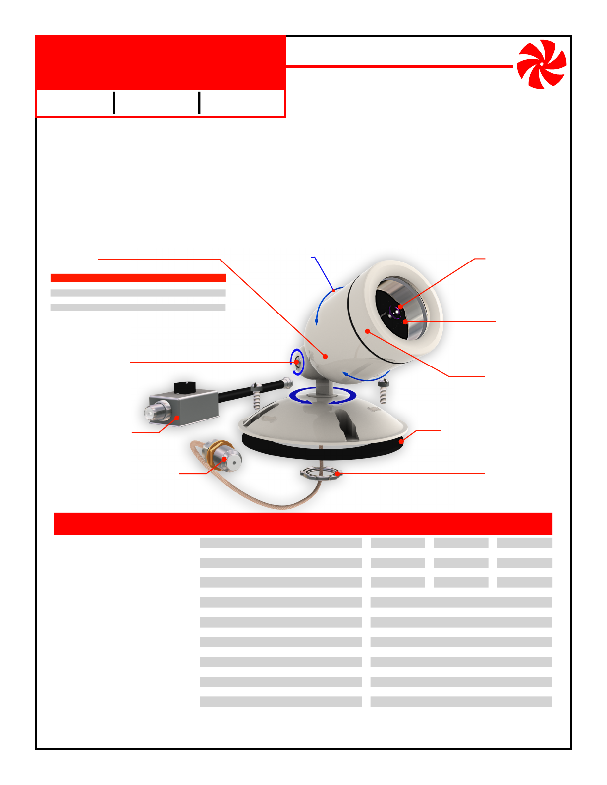
1. Camera Assembly (Camera, Modulator, Housing, Housing Cap, Elbow Bracket, Locking Ring,
Base, Gasket, Video/Power Connector).
2.
Power Injector and 12V DC 300mA Power Transformer (Center Conductor Positive).
3.
Mounting hardware (Mounting Screws, Grounding Strap and Screw).
Housing
Available in choice of colors:
B/W camera Color camera Day/Night Color Housing
NM-MODCAM-BW
NM-MODCAM-BB
NM-MODCAM-BI
NM-MODCAM-BS
Elbow Bracket
Adjusts camera angle at base,
screw, and housing. Installs in
1/2” junction box covers.
NM-MODCAM-CW
NM-MODCAM-CB
NM-MODCAM-CI
NM-MODCAM-CS
NM-MODCAM-HW
NM-MODCAM-HB
NM-MODCAM-HI
NM-MODCAM-HS
White
Black
Ivory
Silver
Color
Housing is adjustable
180˚ in either direction.
Camera Lens
Comes prefocused from
factory but can be adjusted
by rotating in either direction.
Modulator
Switch bank sets output
channel: UHF 14-69
CABLE 70-94, 100-125.
Housing Cap
Externally threaded to accept
37mm lenses and accessories.
Day/Night
NM-MODCAM
Power Injector
Connects power transformer to coax
for One Wire Vide
o™ installation.
Video/Power Connector
Power and video share one coax
through female F connector.
FEATURES
Modulator built into camera
One Wire Video™ installation
Combines with existing TV channels
Viewable on multiple televisions
Excellent image quality
Tough billet aluminum housing
Weather resistant enclosure
Internally routed cables
Mounts to standard electrical fixtures
Mounts directly to walls and ceilings
Works in low light conditions
Accepts photo lens accessories
Adjustable camera angles
Tamper resistant wiring
Includes power supply and power injector
1 year limited warranty
Base, Gasket & Screws
Mount to round 4” junction box.
Locking Ring
Secures elbow bracket to
base at desired position.
SPECIFICATIONS B/W Color Day/Night Color
Camera Lens:
Image Sensor:
Resolution:
Field of View:
Min Illumination:
Infrared Sensitivity:
Modulation Method:
Output Channel:
Output Level:
Output Connector:
Cable Type:
Power Requirement:
Power Connector:
External Accessory Threads:
Housing Size:
Base Size:
Mounting Holes:
Weight:
3.6mm
1/3” CCD
350 lines
72˚ Horizontal
0.7 Lux F2.0
1/4” CCD
470 lines
54˚ Horizontal
0.5 Lux F1.2
Yes
Digital Crystal PLL
UHF 14-69, CABLE 70-94, 100-125
+30dBmV
Female F, 75 Ohm
RG59, RG6 or better
12V DC, 300mA
5.5mm OD, 2.1mm ID, center positive
37mm x .75 pitch
2.13“ dia. x 3” long
4.5” dia., .75” high, 1/2“ hole
3.5” centers
3.7mm
No
1 lb.
(subject to change without notice)
3.6mm
1/3” CCD
470 lines
72˚ Horizontal
0.3 Lux F1.2
Yes
NetMedia, Inc., 10940 N. Stallard Place, Tucson, Arizona 85737 (520) 544-4567 Fax: (520) 544-0800 Email: sales@netmedia.com www.netmedia.com
MAN-MODCAM REV0704A
Page 2
NM-MODCAM
DO NOT CUT OR SPLICE THE CAMERA’S CABLE. MODIFYING THE UNIT IN ANY WAY WILL VOID THE WARRANTY.
Installation Procedures:
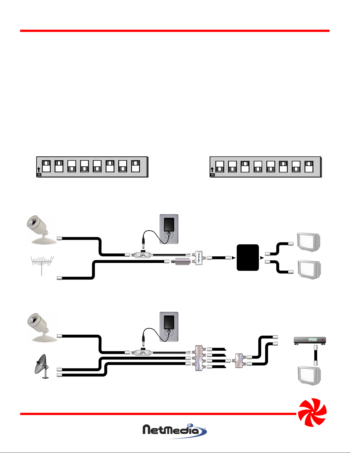
1. Remove the Housing Cap from the camera assembly and set the channel with the switches as shown in Figure 1.
Choose an unused channel that matches the tuning mode of the televisions. With antenna tuning, choose a UHF channel from 14-69. With cable tuning, choose a CABLE channel from 70-94 or 100-125. There must be at least one blank
channel on either side of the modulated channel to separate it from any other broadcast, cable, or modulated source.
When combining with cable service, be aware that digital data typically interferes with channels 80-117, even when
not subscribed to digital services. Channels 120-125 often work without any filtering.
2. Ensure that the camera is grounded with the ground strap as shown in the FCC Information. Connect a coax cable from
the camera’s F connector to the “MOD” side of the Power Injector. Connect the “TV” side of the Power Injector to the
grounded coax from a television or distribution system. Connect the 12V DC 300mA power supply to an AC outlet and
the Power Injector. The camera picture is now available on the programmed TV channel.
3. Mount the base to the junction box (not included) and adjust the camera assembly for proper viewing. When satisfied,
secure all adjustment points.
80 40 20 10 8 4 2 1
UHF Channel 25
ON
OFF
80 40 20 10 8 4 2 1
CABLE Channel 125
Add the numbers
printed on the
circuit board.
ON
OFF
Figure 1 - Setting the modulated channel with the switches. Valid channels are UHF 14-69, CABLE 70-94, 100-125.
Distribution
Panel
or Splitter
Camera
Main cable or
Antenna
Power Injector
Optional Ch. 70-80 Filter (NM-CNF7080)
when there are no clear cable channels.
Splitter/
Combiner
Figure 2 - Connecting the camera to an antenna or cable service and distributing to multiple televisions.
NM-MODCAM
Television
Television
Sat In
Camera
Dual LNB
Satellite
Power Injector
Satellite
Multiswitch
w/Ant input
Satellite
Diplexer
Ant In
Figure 3 - Connecting the camera to a satellite system and distributing to multiple televisions.
NetMedia, Inc., 10940 N. Stallard Place, Tucson, Arizona 85737 (520) 544-4567 Fax: (520) 544-0800 Email: sales@netmedia.com www.netmedia.com
MAN-MODCAM REV0704A
Satellite Receiver
Television
Page 3

Modulated Camera
Indoor/Outdoor Weather Resistant
FCC Information (U.S.A.):
Important: This product, when installed as specified below, meets FCC
requirements. Modifications not expressly approved by NetMedia
may void your authority, granted by the FCC, to use the product.
Failure to follow all installation instructions could void your FCC
authorization to use the product in the USA.
Modulated Cameras:
FCC compliance requires fastening the included grounding strap
from the camera’s F connector to the camera’s base as shown in Figure
4. The connecting cable’s shielding must be grounded. If the cable is
not grounded, the camera base must be mounted to a grounded
metal electrical junction box.
Compliance Information Statement
(Declaration of Conformity Procedure)
We,
NetMedia, Inc.
10940 N. Stallard Pl.
Tucson, AZ 85737
(520-544-4567)
declare under our sole responsibility that the following products,
Type of Equipment: Security Camera
Model: NM-MODCAM-BW Model: NM-MODCAM-CW Model: NM-MODCAM-HW
Model: NM-MODCAM-BB Model: NM-MODCAM-CB Model: NM-MODCAM-HB
Model: NM-MODCAM-BI Model: NM-MODCAM-CI Model: NM-MODCAM-HI
Model: NM-MODCAM-BS Model: NM-MODCAM-CS Model: NM-MODCAM-HS
to which this declaration relates are in conformity with the Title 47
of the US Code of Federal Regulations, Part 15 covering Class B digital devices.
Figure 4 - Grounding the camera through
the base with a grounded coax
NM-MODCAM
Operation is subject to the following two conditions:
(1) this device may not cause harmful interference, and
(2) this device must accept any interference received, including interference that may cause undesired operation.
NOTE: This equipment has been tested and found to comply with the limits for a class B digital device, pursuant to Part15 of the FCC rules.
These limits are designed to provide reasonable protection against harmful interference in a residential installation. This equipment
generates, uses, and can radiate radio frequency energy and, if not installed and used in accordance with the instructions, may cause
harmful interference to radio or television communications. However, there is no guarantee that the interference will not occur in a
particular installation. If this equipment does cause harmful interference to radio or television reception, which can be determined by
turning the equipment off and on, the user is encouraged to try to correct the interference by one or more of the following measures:
* Reorient or relocate the receiving antenna.
* Increase the separation between the equipment and receiver.
* Connect the equipment to a different outlet on a circuit other than the one the receiver is connected to.
* Consult the dealer or an experienced radio/TV technician for help.
One Year Limited Warranty
NetMedia, Inc. warrants this product to be free from defects in materials and workmanship under normal use and service for One Year
from the date of purchase or NetMedia will repair or, at its option, replace the defective product. Please keep your purchase receipt. In the
unlikely event that you need warranty service, call NetMedia at 1-520-544-4567 for a Return Material Authorization (RMA) number. Then,
return the product, with the RMA number clearly marked on the package, by a traceable method with freight pre-paid and accompanied
by a copy of the purchase receipt to:
Attn: Customer Service, NetMedia, Inc. 10940 N. Stallard Place, Tucson, AZ 85737-9527
No expressed or implied warranty is made for any defects in this product which result from accident, abuse, failure to operate the product
in accordance with relevant instructions, neglect, immersion in or exposure to chemicals or liquid, extreme climate, excessive wear and
tear and defect resulting from other extraneous causes such as unauthorized disassembly, repair and or modification. Any implied
warranty arising from the sale of this product, including implied warranties of merchantability and fitness for a particular purpose, are
limited to the warranty stated above. NetMedia shall not be responsible for any loss, damages or expenses, whether direct, consequential
or incidental that arise from the use or inability to use this product. Some states do not allow limitation of incidental or consequential
damages, so the above limitations and exclusions may not apply to you. This warranty gives you specific legal rights, and you may have
other rights, which vary from state to state.
MAN-MODCAM REV0704A
Page 4

Frequently Asked Questions
Q- Why do the light areas of the picture look washed out?
A- The camera’s automatic iris must decide how much to open for shadow areas or close for light areas. When a picture has both light
and shadow, the camera adjusts the iris based on the percentage of each area in the image. If it decides to open more for the shadow
portions then the light areas will be overexposed. In addition, cameras that are designed for low light or infrared sensitivity typically
favor the shadow areas and look more washed out under bright conditions. Try adjusting the image field so that more light areas are
visible and see if the iris closes to improve the picture. It is normal though, that as the lighting conditions change throughout the day,
so will the camera iris and the picture’s dark or light areas.
Q- Why are the shadow areas too dark to see much detail?
A- This is like the washed out question above except opposite. In this case, the camera’s automatic iris is opening more for the light areas
at the expense of the shadow areas. Try adjusting the image field so that more shadow areas are visible and see if the iris opens to
improve the picture. Keep in mind though, that the camera still does need some kind of light in order to see. If necessary, add some
lighting to the dark area to improve visibility.
Q- How do I find out if the camera is working when I can’t see it on any televisions?
A- Start with a basic setup: connect camera to coax, coax to power injector, power injector to TV with no amplifiers, splitters, filters, cable
boxes or other devices involved. Set the camera to a channel that matches the TV mode: 14-69 for Antenna tuning; 70-94 or 100-125
for Cable tuning. If the TV can tune channel 70 or above, then it is probably in Cable tuning mode. Set a simple channel like 20 or 120
and look for it on the TV. Check power, power injector direction, connections, cables, TV tuning mode, and camera switches to correct
any problems. You must see the camera picture to confirm that it works in this basic setup before moving on to more complex setups.
Q- Why does the camera or cable service picture go bad when the two are combined together?
A- The signals should be combined at the beginning of the distribution system before the cable service goes through any splitters. Make
sure you are not using any diplexers to split or combine. Once done, there is either interference or the signals are not balanced. Most
interference comes from invisible digital data that is on the line even when not subscribed to it. Set the camera for a clear channel, try
120, or use a filter to remove the digital/analog interference. When there is no interference you can balance the signals by amplifying
the weaker, snowy one before the two are combined. 10 to 20dBmV is usually enough, too much will degrade the other signal.
Q- Can the camera be combined with digital cable service?
A- Yes. The difficulty is in finding a clear channel for the camera. The digital data usually takes up the analog channel range of 80-117 so
channel 120 is a good place to start. Analog 120 on the TV will not conflict with digital 120 on the cable box. If you cannot find a clear
channel then you will have to use a notch or low pass filter on the cable service before you combine it with the camera. Make sure the
filter does not remove any subscribed digital services including an Internet connection. If only one location is using the digital
services and it does not need to see the camera, you can split its run off before the main line is filtered and combined with the camera.
This prevents the filter from disrupting the digital data while enabling the camera to appear on the rest of the TV’s.
NM-MODCAM
Q- How can I see the camera when the TV uses a cable box?
A- There are a few ways but they all involve bypassing the cable box and using the TV tuner to see the camera. Combine the camera with
the cable service and check its picture by connecting the coax directly to the TV. Any splitters, filters, or amplifiers you use for
combining are separate from the ones used to bypass the cable box. After verifying the camera picture, split the coax two ways with
one side going to the cable box. If you use the cable box S-Video or composite output then the other side of the splitter goes directly
to the TV. If you use the cable box coax output and there is only one coax input on the TV, then you must use a ch. 3/4 filter (included
with NM-ACB3) and recombine the coaxes as shown in Figure 5. In any case, view the cable box through the appropriate TV
connection, Video 1, ANT 2, channel 3/4, then change the TV (not the cable box) to the camera channel.
Cable Box
Camera
Main cable or
Antenna
Power Injector
Optional NM-CNF7080 Ch. 70-80 Notch Filter
when there are no clear cable channels.
The notch filter does not bypass the cable box.
Splitter/
Combiner
NetMedia Cable Box
Bypass/Combiner
Kit NM-ACB3
The kit filter does not
make clear channels
for the camera.
Figure 5 - Bypassing a digital or analog cable box and recombining to a single coax input on the TV. The kit’s filter
removes any conflict on channel 3 or 4. Switch TV from the cable box to the camera channel.
NetMedia, Inc., 10940 N. Stallard Place, Tucson, Arizona 85737 (520) 544-4567 Fax: (520) 544-0800 Email: sales@netmedia.com www.netmedia.com
Television
MAN-MODCAM REV0704A
 Loading...