

Page 1
Single Channel Stereo Modulator
NM-MM70S
The NetMedia MM70S Stereo Modulator converts composite video and stereo audio to an MTS Stereo
television signal. The selectable channel is viewed with a standard television (SDTV) tuner. Once modulated, the signal is no longer bound to a single monitor or TV; it can be combined with antenna, cable, or
satellite signals for distribution to multiple TV’s throughout the location. This provides convenient viewing access to security cameras, DVR’s, or other audio/video (A/V) sources such as DVD’s and VCR’s.
Product Includes:
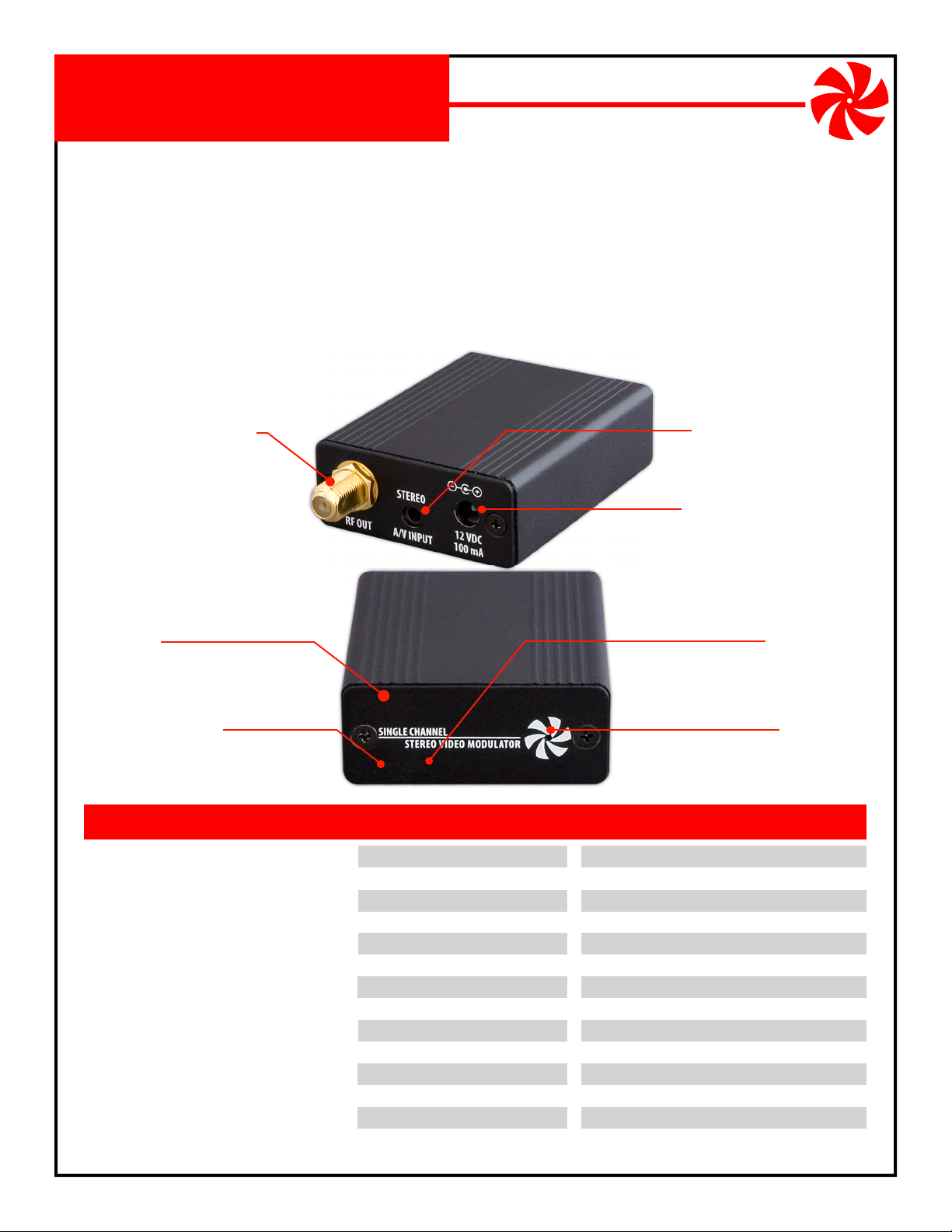
1. Modulator Assembly (A/V Input Connector, RF Output Connector,
Power Input Connector, End Plate, Switch Bank, Gain Adjustment, Power LED).
1
2V DC 100mA Power Transformer (Center Conductor Positive).
2.
3. 3.5mm to 3 RCA A/V Cable.
Baseband A/V to SDTV Converter
NM-MM70S
RF Output Connector
Connects modulated stereo output
channel to video distribution
system and televisions.
Composite video and stereo audio input
A/V Input Connector
for A/V sources such as cameras, quads,
DVR’s, DVD’s, etc.
Power Input Connector
12V DC 100mA, center positive.
End Plate
Remove to access Switch Bank
and Gain Adjustment.
Gain Adjustment
Behind End Plate turn clockwise to increase
output level to over +30dBmV.
FEATURES
Stereo audio input and output
Digital PLL locked audio & video - no drift
Combines with existing TV channels
Viewable on multiple televisions
UHF & Cable channel coverage
Channel retained during power outage
Tough aluminum housing
Includes power supply
5 year limited warranty
NetMedia, Inc., 10940 N. Stallard Place, Tucson, Arizona 85737 (520) 544-4567 Fax: (520) 544-0800 Email: sales@netmedia.com www.netmedia.com
SPECIFICATIONS
Modulation Method:
Output Channel:
Output Level:
Output Connector:
Input Connector:
Video Input Signal:
Audio Input Signal:
Audio Output:
Cable Type:
Power Requirement:
Power Connector:
Housing Size:
Weight:
Digital Crystal PLL
SDTV: UHF 14-69, CABLE 70-94, 100-125
Selectable, 0 to +30dBmV
Female F, 75 Ohm
3.5mm A/V jack
Baseband, 75 Ohm, 1 Vp-p
Stereo, 75,000 Ohm, 1 Vp-p
MTS Stereo
RG59, RG6 or better
12V DC, 100mA
5.5mm OD, 2.1mm ID, center positive
3.2“ long x 2.2” wide x 0.9“ high
4.0 oz.
(subject to change without notice)
Switch Bank
Behind End Plate -
Sets output channel:
CABLE 70-94, 100-125.
Power LED
Indicates that unit is on.
UHF 14-69
MAN-MM70S REV0708A
Page 2
NM-MM70S
Installation Procedures:
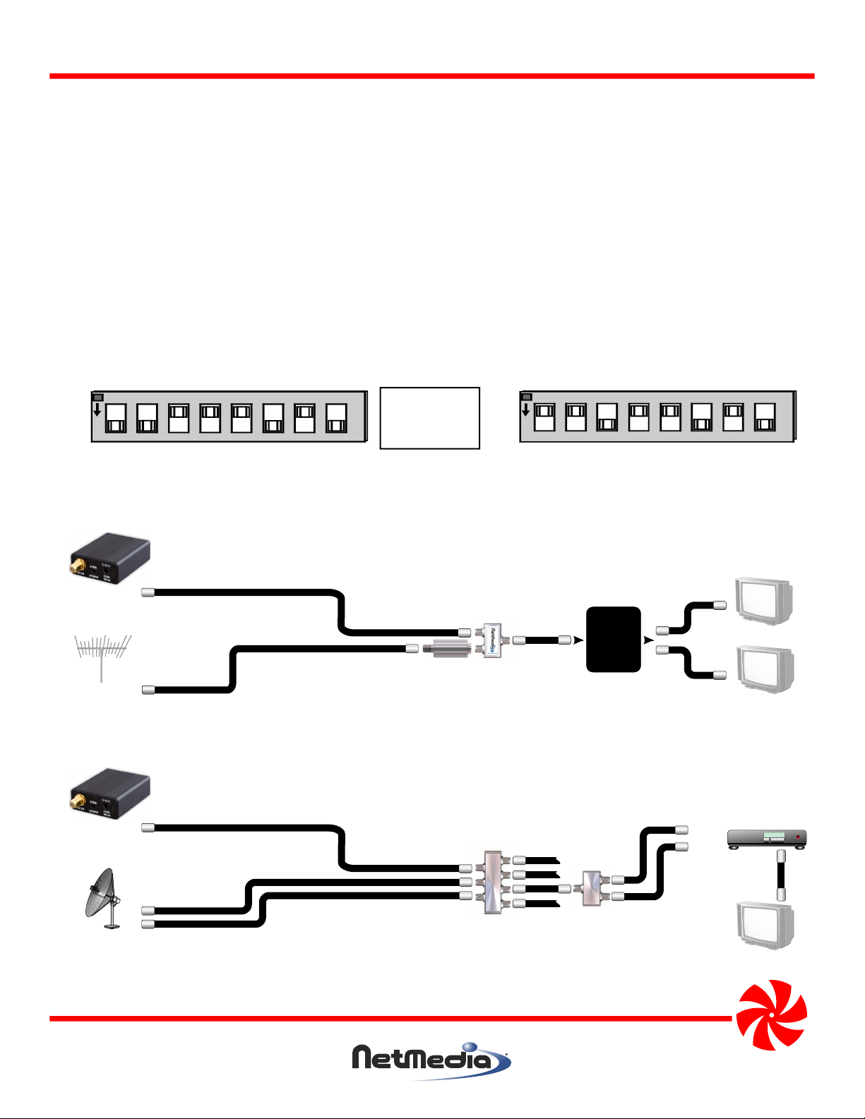
1. Remove the End Plate from the modulator assembly and set the channel with the switches as shown in
Figure 1. Choose an unused channel that matches the tuning mode of the televisions. With antenna tuning,
choose a UHF channel from 14-69. With cable tuning, choose a CABLE channel from 70-94 or 100-125. There
must be at least one blank channel on either side of the modulated channel to separate it from any other
broadcast, cable, or modulated source. When combining with cable service, be aware that digital data
typically interferes with channels 80-117, even when not subscribed to digital services. If no channels are
available then a filter such as NetMedia’s CNF7080 (ch. 70-80) may be necessary.
2. Connect a video source to the A/V Cable’s yellow RCA video input jack. Adapter’s such as BNC to RCA may
be used as necessary. If audio is available, connect it to the A/V Cable’s white and red RCA audio input jacks.
Insert the A/V Cable’s 3.5mm plug into the modulator’s A/V Input Connector.
3. Connect a coax cable from the modulator’s F connector to the coax from a television or distribution system.
Connect the 12V DC 100mA power supply to an AC outlet. The modulator picture is now available on the
programmed TV channel.
NM-MM70S
OFF
ON
Add numbers
switched ON
to set channel.
80 40 20 10 8 4 2 1
CABLE Channel 125
OFF
ON
80 40 20 10 8 4 2 1
UHF Channel 25
Figure 1 - Setting the modulated channel with the switches. Valid channels are UHF 14-69, CABLE 70-94, 100-125.
Distribution
Modulator
Main cable or
Antenna
Optional Ch. 70-80 Filter (NM-CNF7080)
when there are no clear cable channels.
Splitter/
Combiner
Panel
or Splitter
Figure 2 - Connecting the modulator to an antenna or cable service and distributing to multiple televisions.
Television
Television
Modulator
Dual LNB
Satellite
Satellite
Multiswitch
w/Ant input
Satellite
Diplexer
Sat In
Ant In
Figure 3 - Connecting the modulator to a satellite system and distributing to multiple televisions.
NetMedia, Inc., 10940 N. Stallard Place, Tucson, Arizona 85737 (520) 544-4567 Fax: (520) 544-0800 Email: sales@netmedia.com www.netmedia.com
Satellite Receiver
Television
MAN-MM70S REV0708A
Page 3

Single Channel Stereo Modulator
Baseband A/V to SDTV Converter
FCC Information (U.S.A.):
Important: This product, when installed as specified below,
meets FCC requirements. Modifications not expressly
approved by NetMedia may void your authority, granted by
the FCC, to use the product. Failure to follow all installation
instructions could void your FCC authorization to use the
product in the USA.
Modulators:
FCC compliance requires operating the modulator with both
end caps securely closed and fastened.
Compliance Information Statement
(Declaration of Conformity Procedure)
We,
NetMedia, Inc.
10940 N. Stallard Pl.
Tucson, AZ 85737
(520-544-4567)
declare under our sole responsibility that the following products,
Type of Equipment: Modulator
Model: MM70S
to which this declaration relates are in conformity with the Title 47
of the US Code of Federal Regulations, Part 15 covering Class B digital devices.
Operation is subject to the following two conditions:
(1) this device may not cause harmful interference, and
(2) this device must accept any interference received, including interference that may cause undesired operation.
NM-MM70S
NOTE: This equipment has been tested and found to comply with the limits for a class B digital device, pursuant to Part15 of the FCC rules.
These limits are designed to provide reasonable protection against harmful interference in a residential installation. This equipment
generates, uses, and can radiate radio frequency energy and, if not installed and used in accordance with the instructions, may cause
harmful interference to radio or television communications. However, there is no guarantee that the interference will not occur in a
particular installation. If this equipment does cause harmful interference to radio or television reception, which can be determined by
turning the equipment off and on, the user is encouraged to try to correct the interference by one or more of the following measures:
* Reorient or relocate the receiving antenna.
* Increase the separation between the equipment and receiver.
* Connect the equipment to a different outlet on a circuit other than the one the receiver is connected to.
* Consult the dealer or an experienced radio/TV technician for help.
Five Year Limited Warranty
NetMedia, Inc. warrants this product to be free from defects in materials and workmanship under normal use and service for Five Years
from the date of purchase or NetMedia will repair or, at its option, replace the defective product. Please keep your purchase receipt. In the
unlikely event that you need warranty service, call NetMedia at 1-520-544-4567 for a Return Material Authorization (RMA) number. Then,
return the product, with the RMA number clearly marked on the package, by a traceable method with freight pre-paid and accompanied
by a copy of the purchase receipt to:
Attn: Customer Service, NetMedia, Inc. 10940 N. Stallard Place, Tucson, AZ 85737-9527
No expressed or implied warranty is made for any defects in this product which result from accident, abuse, failure to operate the product
in accordance with relevant instructions, neglect, immersion in or exposure to chemicals or liquid, extreme climate, excessive wear and
tear and defect resulting from other extraneous causes such as unauthorized disassembly, repair and or modification. Any implied
warranty arising from the sale of this product, including implied warranties of merchantability and fitness for a particular purpose, are
limited to the warranty stated above. NetMedia shall not be responsible for any loss, damages or expenses, whether direct, consequential
or incidental that arise from the use or inability to use this product. Some states do not allow limitation of incidental or consequential
damages, so the above limitations and exclusions may not apply to you. This warranty gives you specific legal rights, and you may have
other rights, which vary from state to state.
MAN-MM70S REV0708A
Page 4

Frequently Asked Questions
Q- How do I find out if the modulator is working when I can’t see it on any televisions?
A- Start with a basic setup: connect modulator to coax and coax to a standard TV with no amplifiers, splitters, filters, cable boxes or
NM-MM70S
other devices involved. Set the modulator to a channel that matches the TV mode: 14-69 for Antenna tuning; 70-94 or 100-125
for Cable tuning. If the TV can tune channel 70 or above, then it is probably in Cable tuning mode. Set a simple channel like 20 or
120 and look for it on the TV. Check power, connections, cables, TV tuning mode, and modulator channel to correct any problems.
You must see the modulator output to confirm that it works in this basic setup before moving on to more complex setups.
Q- How can I view modulated signals on my security monitor or DVR?
A- Equipment that does not have a tuner, such as a security monitor, Quad display, or DVR, will require a demodulator (any TV tuner
device with a composite video output such as a VCR) for each modulated signal that you want to convert. To avoid this extra
expense and complication, you should modulate the signals after they are run through a monitor or DVR.
Q- How can I view modulated signals with high definition (HD) devices?
A- Proprietary, digital, or high definition (HD) tuners, including satellite receivers, cable boxes, and HD TV’s or monitors may require
a separate standard (SD) tuner, such as an SD TV or VCR. Satellite receivers often have an antenna input that is passed to an SDTV
tuner when the receiver is turned off. Cable boxes can be bypassed as described below. If the HD box, and TV or monitor does not
have an SDTV tuner then an additional device, such as a VCR, will be required to select any modulated channels for viewing
through the composite input of the TV or monitor.
Q- Why does the modulator or cable service picture go bad when the two are combined together?
A- The signals should be combined at the beginning of the distribution system before the cable service goes through any splitters.
Make sure you are not using any satellite diplexers to split or combine. Once done, there is either interference or the signals are
not balanced. Most interference comes from invisible digital data that is on the line even when not subscribed to it. First set the
modulator for clear channels, perhaps 120-125, or use a filter to remove any competing signals. Once there is no interference you
can balance the signals by amplifying the weaker, snowy one before the two are combined. +10 to +20dBmV is usually enough,
too much will degrade the other signal.
Q- Can the modulator be combined with digital cable service?
A- Yes. The difficulty is in finding a clear channel for the modulator. The digital data usually takes up the analog channel range of
80-117 so channel 120 is a good place to try. Analog 120 on the TV will not conflict with digital 120 on the cable box. If you cannot
find a clear channel then you will have to use a low pass or notch filter (NM-CNF7080) on the cable service before you combine
it with the modulator. The filter may remove analog channels but make sure it does not remove any subscribed digital services
including an Internet connection. If only one location is using the digital services and it does not need to see the modulator, you
can split its run off before the main line is filtered and combined with the modulator. This prevents the filter from disrupting the
digital data while enabling the modulator to appear on the rest of the TV’s.
Q- How can I view modulated signals with a TV that uses a cable box?
A- There are a few ways but they all involve bypassing the cable box and using the SDTV tuner to see modulated signals. Combine
the modulator with the cable service and check its picture by connecting the coax directly to the TV. Any splitters, filters, or
amplifiers you use for combining are separate from the ones used to bypass the cable box. After verifying the modulator picture,
split the coax two ways with one side going to the cable box. If you use the cable box S-Video, composite, or component A/V
outputs then the other side of the splitter goes directly to the TV. If you use the cable box coax output and there is only one coax
input on the TV, then you must use a ch. 3/4 filter (included with NM-ACB3) and recombine the coaxes as shown in Figure 4. In any
case, view the cable box through the appropriate TV connection, Video 1, ANT 2, channel 3/4, then change the TV (NOT THE
CABLE BOX) to the modulated channels.
Modulator
Cable Box
Splitter/
Main cable or antenna
Combiner
Optional NM-CNF7080 Ch. 70-80 Notch Filter
when there are no clear cable channels.
The notch filter does not bypass the cable box.
NetMedia Cable Box
Bypass/Combiner
Kit NM-ACB3
The kit filter does not
make clear channels
for the modulator.
Television
Figure 4 - Bypassing a digital or analog cable box and recombining to a single coax input on the TV. The kit’s filter
removes any conflict on channel 3 or 4. Switch TV from the cable box to the modulator channel.
NetMedia, Inc., 10940 N. Stallard Place, Tucson, Arizona 85737 (520) 544-4567 Fax: (520) 544-0800 Email: sales@netmedia.com www.netmedia.com
MAN-MM70S REV0708A
 Loading...