

Page 1
Page 2

- ITALIANO -
- 2 -
INTRODUZIONE
Vi ringraziamo per la scelta del nostro prodotto.
Gli accessori descritti in questo manuale sono prodotti di alta qualità, attentamente progettati e
costruiti allo scopo di garantire le migliori prestazioni.
Questo manuale contiene le istruzioni dettagliate per l‟uso e l‟installazione del prodotto.
Per informazioni sull’utilizzo e per ottenere il massimo delle prestazioni dalla Vostra
apparecchiatura, il presente manuale dovrà essere conservato con cura vicino al NetMan
plus e CONSULTATO PRIMA DI OPERARE SULLO STESSO.
Simboli utilizzati in questo manuale:
Avvertimento
Indica informazioni importanti che non devono essere ignorate
Informazione
Fornisce note e suggerimenti utili per l‟utente
SICUREZZA
Questa parte del manuale contiene precauzioni da seguire scrupolosamente in quanto
riguardano la SICUREZZA.
Il dispositivo è stato realizzato per l‟uso professionale e quindi non è adatto per l‟uso in
ambiente domestico.
Il dispositivo è stato progettato per funzionare soltanto in ambienti chiusi. È bene installarlo
in ambienti privi di liquidi infiammabili, gas o altre sostanze nocive.
Evitare che acqua, liquidi in genere e/o altri oggetti estranei entrino nel dispositivo.
In caso di guasto e/o di cattivo funzionamento dell‟apparecchio astenersi da qualsiasi
tentativo di riparazione e rivolgersi esclusivamente al centro assistenza.
Questo apparecchio dovrà essere destinato solo all‟uso per il quale è stato espressamente
concepito. Ogni altro uso è da considerarsi improprio e quindi pericoloso. Il costruttore non
può essere considerato responsabile per eventuali danni causati da usi impropri, erronei ed
irragionevoli.
Page 3

- ITALIANO -
- 3 -
TUTELA DELL’AMBIENTE
Nello sviluppo dei suoi prodotti l‟azienda dedica ampie risorse nell‟analisi degli aspetti ambientali.
Tutti i nostri prodotti perseguono gli obiettivi definiti nella politica del sistema di gestione
ambientale sviluppato dall‟azienda in accordo con la normativa vigente.
In questo prodotto non sono utilizzati materiali pericolosi quali CFC, HCFC o amianto.
Nella valutazione degli imballi la scelta del materiale è stata fatta prediligendo materie riciclabili.
Si prega di separare i differenti materiali costituenti l‟imballo e smaltire secondo le normative
vigenti nel paese di utilizzo del prodotto.
SMALTIMENTO DEL PRODOTTO
Il dispositivo contiene al suo interno schede elettroniche e batterie che sono considerate RIFIUTO
TOSSICO. A fine vita del prodotto trattare secondo le legislazioni locali vigenti.
Il corretto smaltimento contribuisce a rispettare l‟ambiente e la salute delle persone.
© E‟ vietata la riproduzione di qualsiasi parte del presente manuale anche se parziale salvo autorizzazione
della ditta costruttrice.
Per scopi migliorativi, il costruttore si riserva la facoltà di modificare il prodotto descritto in qualsiasi
momento e senza preavviso.
Page 4

- ITALIANO -
- 4 -
SOMMARIO
PRESENTAZIONE _________________________________________________ 6
DESCRIZIONE __________________________________________________________ 6
APERTURA DELL’IMBALLO E VERIFICA DEL CONTENUTO ____________________________ 7
PORTA DI RETE _________________________________________________________ 8
PORTA DI COMUNICAZIONE RS-232 __________________________________________ 8
SERVIZI DI RETE _________________________________________________________ 8
Telnet ___________________________________________________________________ 8
Wake-on-LAN _____________________________________________________________ 8
HTTP ____________________________________________________________________ 9
UDP ____________________________________________________________________ 10
FTP ____________________________________________________________________ 11
Email ___________________________________________________________________ 12
Report __________________________________________________________________ 13
Archivio storico di misure ed eventi dell’inverter ______________________________ 13
Eventlog ________________________________________________________________ 14
Datalog _________________________________________________________________ 14
SENSORI AMBIENTALI (OPZIONALI) __________________________________________ 16
Sensori disponibili _______________________________________________________ 16
INSTALLAZIONE E CONFIGURAZIONE _______________________________ 17
SETTAGGIO DEI JUMPER __________________________________________________ 17
INSTALLAZIONE NETMAN 101 PLUS _________________________________________ 19
INSTALLAZIONE NETMAN 102 PLUS _________________________________________ 19
CONFIGURAZIONE ______________________________________________________ 20
Configurazione via linea seriale RS-232 ______________________________________ 21
Configurazione via telnet __________________________________________________ 21
Salvataggio della configurazione e riavvio con i parametri impostati ______________ 21
Page 5

- ITALIANO -
- 5 -
Menù principale di configurazione __________________________________________ 22
Menù IP config ___________________________________________________________ 24
Menù Time setting ________________________________________________________ 26
Menù NTP Options _______________________________________________________ 27
Menù PVI config _________________________________________________________ 28
Menù Feeding config _____________________________________________________ 29
Menù Services 1 _________________________________________________________ 30
Menù Email config _______________________________________________________ 31
Menù Email logic _________________________________________________________ 32
Menù Miscellaneous ______________________________________________________ 33
Menù Activation 1 ________________________________________________________ 34
Menù Services 2 _________________________________________________________ 34
Menù Wake-On-LAN address _______________________________________________ 35
Menù Wake-On-LAN delay _________________________________________________ 35
Menù Activation 2 ________________________________________________________ 36
Menù Sensors Config _____________________________________________________ 36
Menù I/O Sensors ________________________________________________________ 38
Menu Threshold sens _____________________________________________________ 39
Menù Security ___________________________________________________________ 40
Menù Save and load ______________________________________________________ 42
Configurazione di più dispositivi ____________________________________________ 43
AGGIORNAMENTO FIRMWARE ______________________________________________ 44
Aggiornamento via linea seriale ____________________________________________ 44
Aggiornamento via rete (Netboot) ___________________________________________ 44
DATI TECNICI ____________________________________________________ 45
SPECIFICHE PER IL CABLAGGIO DEL CAVO DI RETE _______________________________ 45
SEGNALI SUL CONNETTORE “SERIAL” _______________________________________ 45
BATTERIA TAMPONE ____________________________________________________ 46
SPECIFICHE TECNICHE ___________________________________________________ 46
Page 6
- ITALIANO -
- 6 -
PRESENTAZIONE
DESCRIZIONE
NetMan plus è un dispositivo che permette di gestire l‟inverter attraverso la vostra LAN (Local Area
Network); l‟accessorio supporta tutti i principali protocolli di rete (TCP/IP, HTTP e così via) ed è
compatibile con reti Ethernet 10/100Mbps IPv4/6; permette quindi di integrare facilmente l‟inverter
in reti di medie e grandi dimensioni.
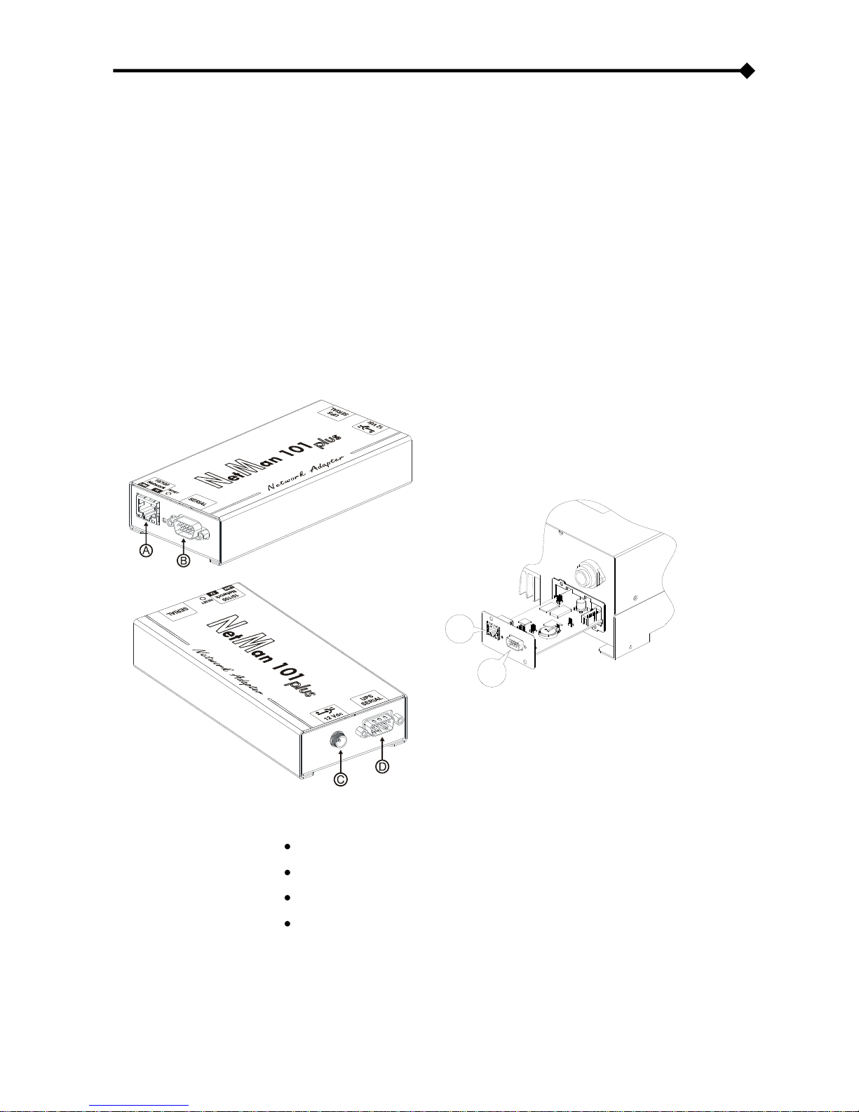
NetMan 101 plus è un accessorio esterno all‟inverter da collegare ad esso tramite cavo seriale;
NetMan 102 plus è una scheda di espansione da inserire nello slot dell‟inverter
Il dispositivo effettua inoltre la registrazione su archivio storico di misure ed eventi dell‟inverter.
NetMan 101 plus
NetMan 102 plus
A
B
A: porta di rete;
B: porta di comunicazione RS-232
C: connettore per l‟alimentazione
D: connettore per il collegamento all‟inverter
NetMan plus
Page 7

- ITALIANO -
- 7 -
APERTURA DELL’IMBALLO E VERIFICA DEL CONTENUTO
Dopo l‟apertura dell‟imballo, per prima cosa procedere alla verifica del contenuto.
L‟imballo dovrà contenere:
NetMan 101 plus
OPPURE
NetMan 102 plus
Cavo seriale null-modem DB9-DB9
Cavo seriale null-modem DB9-DB9
Alimentatore esterno 12Vdc 0,3A
Cavo seriale pin to pin
Page 8

- ITALIANO -
- 8 -
PORTA DI RETE
Il NetMan plus si connette a reti ethernet 10/100 Mbps attraverso il connettore RJ45 (vedi
paragrafo “Specifiche per il cablaggio del cavo di rete”). I led integrati nel connettore descrivono lo
stato della rete:
Led sinistro:
1. acceso e di colore giallo se è presente il link in modalità 10/100Mbps
2. acceso e di colore verde se è presente il link in modalità 10Mbps
Led destro:
1. acceso e di colore giallo durante la trasmissione in modalità full-duplex
2. acceso e di colore verde durante la trasmissione in modalità half-duplex
PORTA DI COMUNICAZIONE RS-232
Il NetMan plus rende disponibile una porta di comunicazione seriale attraverso la quale è possibile:
Configurare il NetMan plus (vedi paragrafo “Configurazione via linea seriale RS-232”)
SERVIZI DI RETE
Il NetMan plus implementa una serie di servizi che si basano sui principali protocolli di rete. Questi
servizi possono essere attivati o disattivati a seconda delle esigenze (vedi paragrafo
“Configurazione”). Di seguito viene riportata una breve descrizione per ciascuno di essi.
Telnet
Mediante un client telnet (disponibile su tutti i principali sistemi operativi) è possibile stabilire una
connessione remota con il NetMan plus per modificare la sua configurazione (vedi paragrafo
“Configurazione via telnet”).
Wake-on-LAN
Il NetMan plus può inviare comandi “Wake-on-LAN” per avviare computer da remoto.
Page 9
- ITALIANO -
- 9 -
HTTP
Tramite il protocollo HTTP (Hyper Text Transfer Protocol) è possibile monitorare lo stato
dell‟inverter mediante un web browser senza dover installare software aggiuntivi. Tutti i web
browser più popolari (Internet Explorer, Safari, Firefox, Netscape Navigator, Konqueror, Opera)
sono supportati.
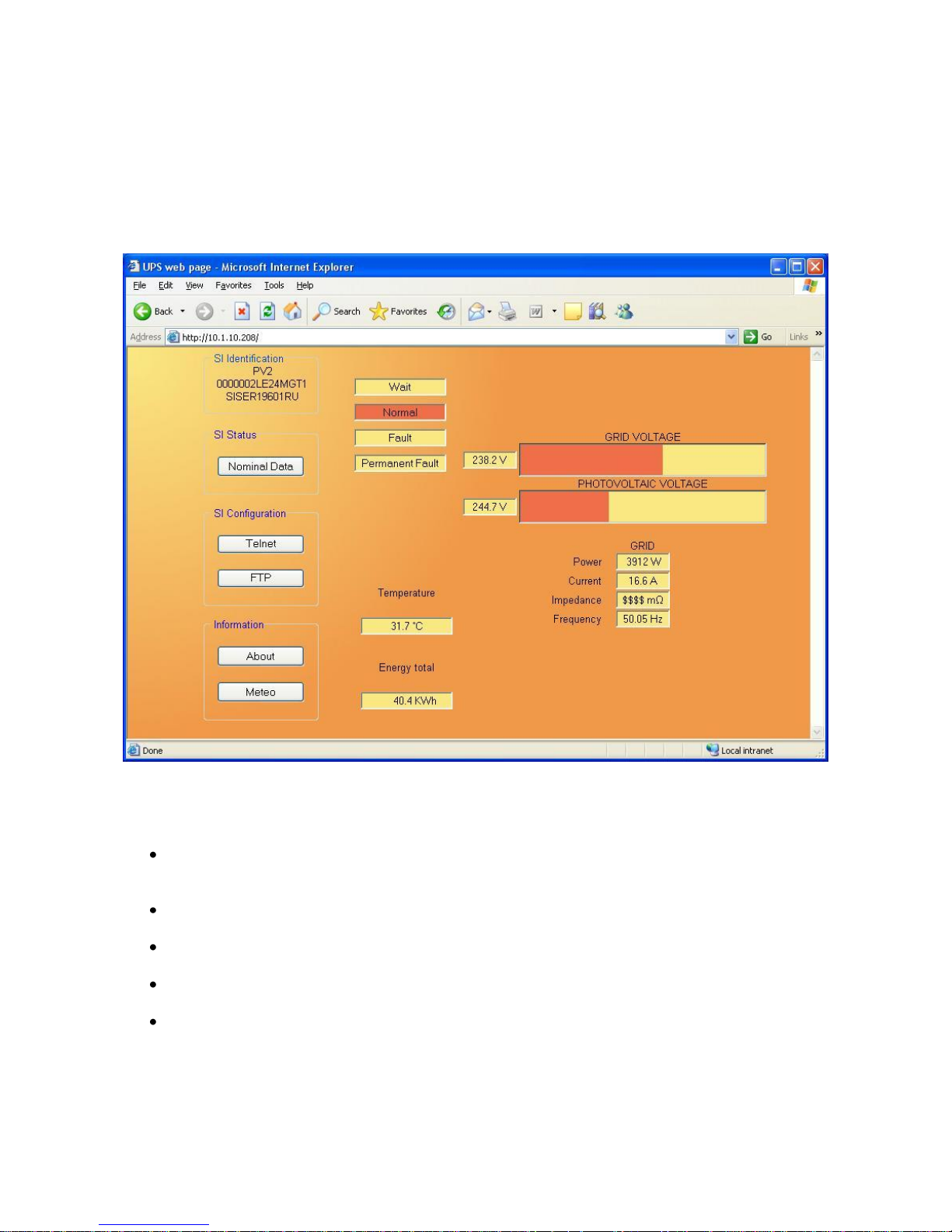
Una volta inserito l‟hostname o l‟indirizzo IP del NetMan plus sul vostro web browser, si
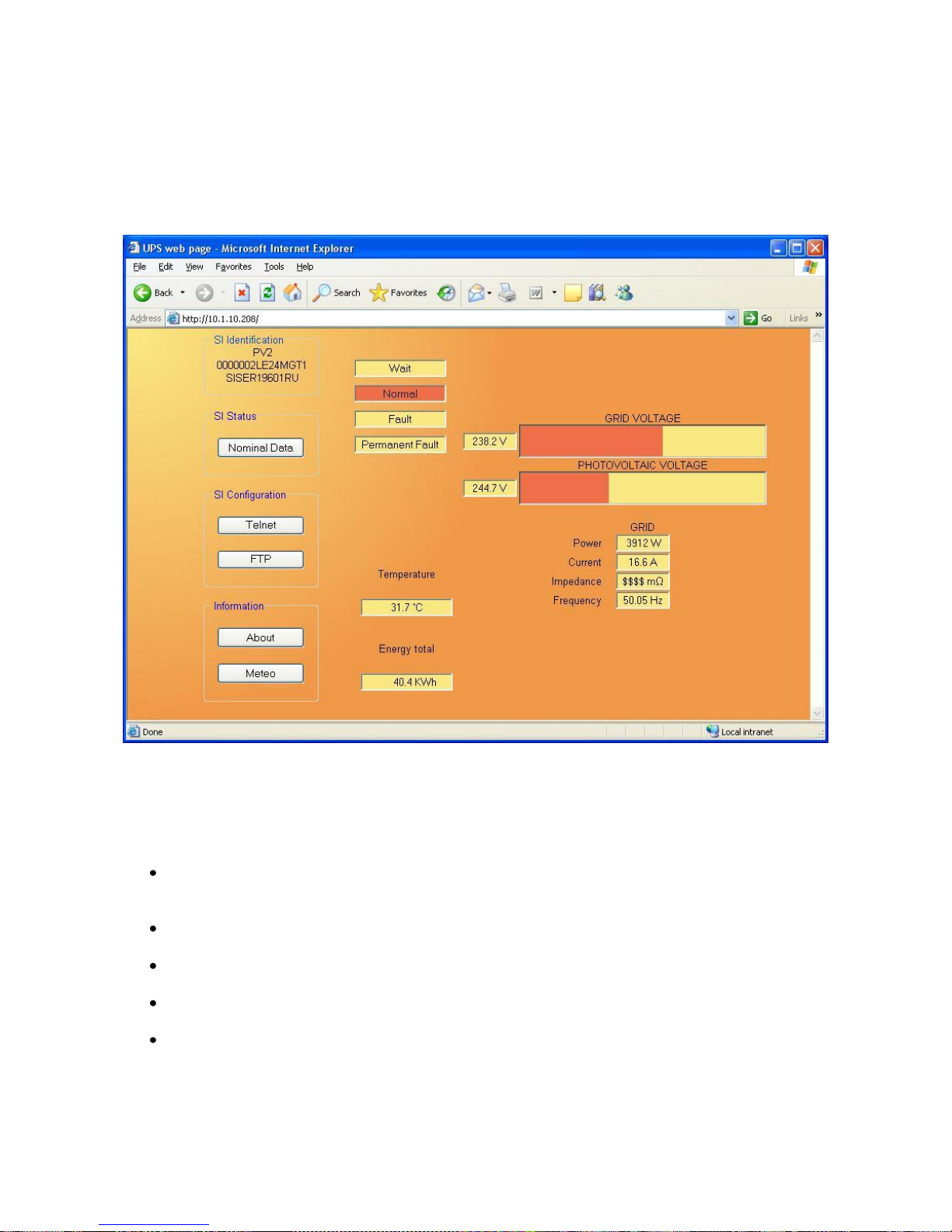
visualizzerà una schermata simile alla seguente, sulla quale sono presenti i principali dati operativi
dell‟inverter.
Esempio di visualizzazione tramite HTTP
Nel lato sinistro della pagina sono presenti i seguenti pulsanti:
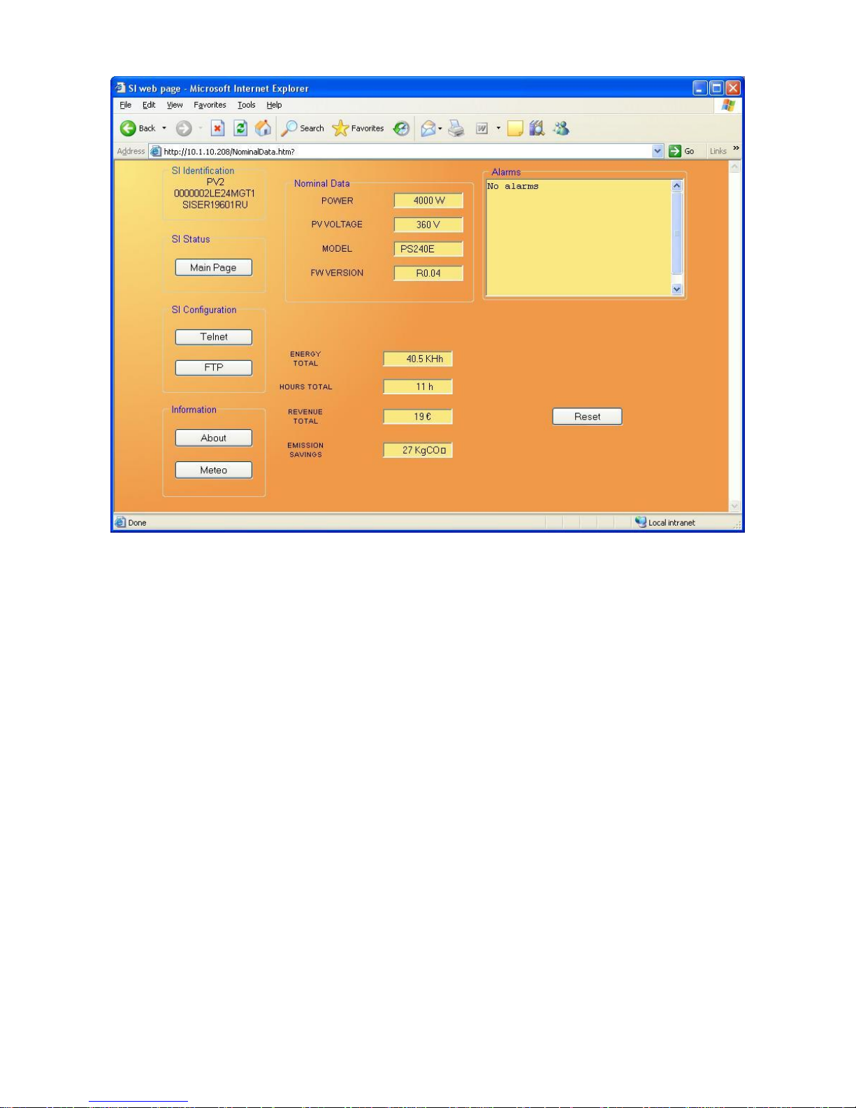
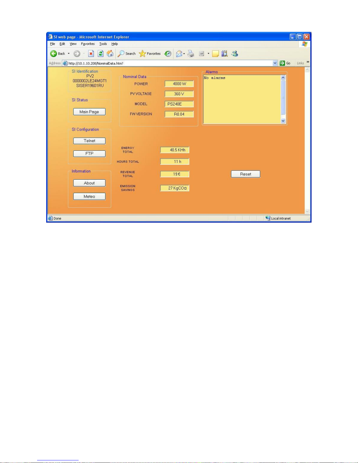
Nominal Data: apre una pagina che visualizza i valori nominali dell‟inverter, la lista degli
allarmi attivi ed i contatori. (vedi immagine pagina seguente)
Telnet: apre una sessione Telnet (vedi paragrafo “Telnet”)
FTP: apre una sessione FTP (vedi paragrafo ”FTP”)
About: apre una pagina con informazioni sul copyright
Meteo: apre una pagina web di previsioni meteo (vedi paragrafo “Feeding config”)
Page 10
- ITALIANO -
- 10 -
Esempio di finestra “Nominal Data”
UDP
UDP (User Datagram Protocol) è un protocollo di rete di basso livello che garantisce velocità nello
scambio dati e bassa congestione di rete. E‟ il protocollo utilizzato dal software SunVision per il
controllo ed il monitoraggio dell‟inverter.
La connessione UDP utilizza di default la porta UDP 33000 ma, a seconda delle esigenze, può
essere configurata su altre porte.
Page 11
- ITALIANO -
- 11 -
FTP
FTP (File Transfer Protocol) è un protocollo di rete utilizzato per lo scambio di file. Il NetMan plus
utilizza questo protocollo per due scopi:
1. download dei file dell‟archivio storico di misure ed eventi dell‟inverter (Datalog e Eventlog)
2. download e upload dei file di configurazione
In entrambi i casi è richiesto un client FTP configurato con questi parametri:
Host: hostname o indirizzo IP del NetMan plus
Utente: “root”
Password: password corrente (configurazione di default: “password”)
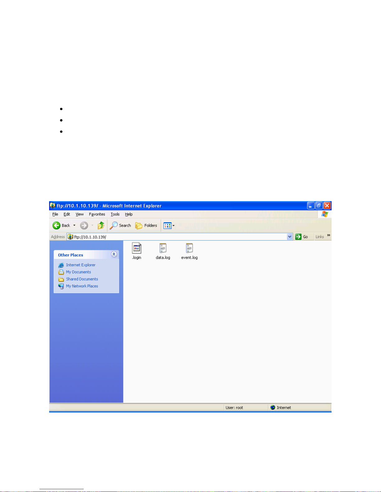
La connessione può essere stabilita anche utilizzando un web browser (tutti i web browser più
popolari sono supportati) inserendo il seguente indirizzo: ftp://root@<indirizzo.NetMan plus>, dove
<indirizzo.NetMan plus> va sostituito con il vero indirizzo del dispositivo. In questo caso verrà
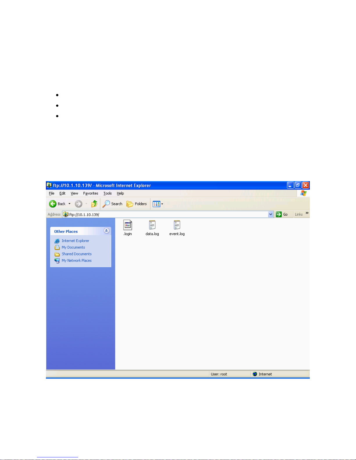
visualizzata una schermata simile alla seguente.
Esempio di connessione FTP
NOTA: quando si stabilisce una connessione FTP, tutte le connessioni HTTP vengono rifiutate.
Page 12
- ITALIANO -
- 12 -
Email
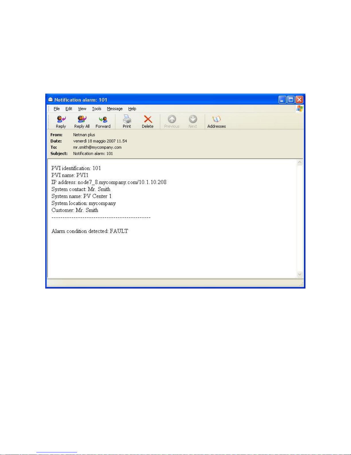
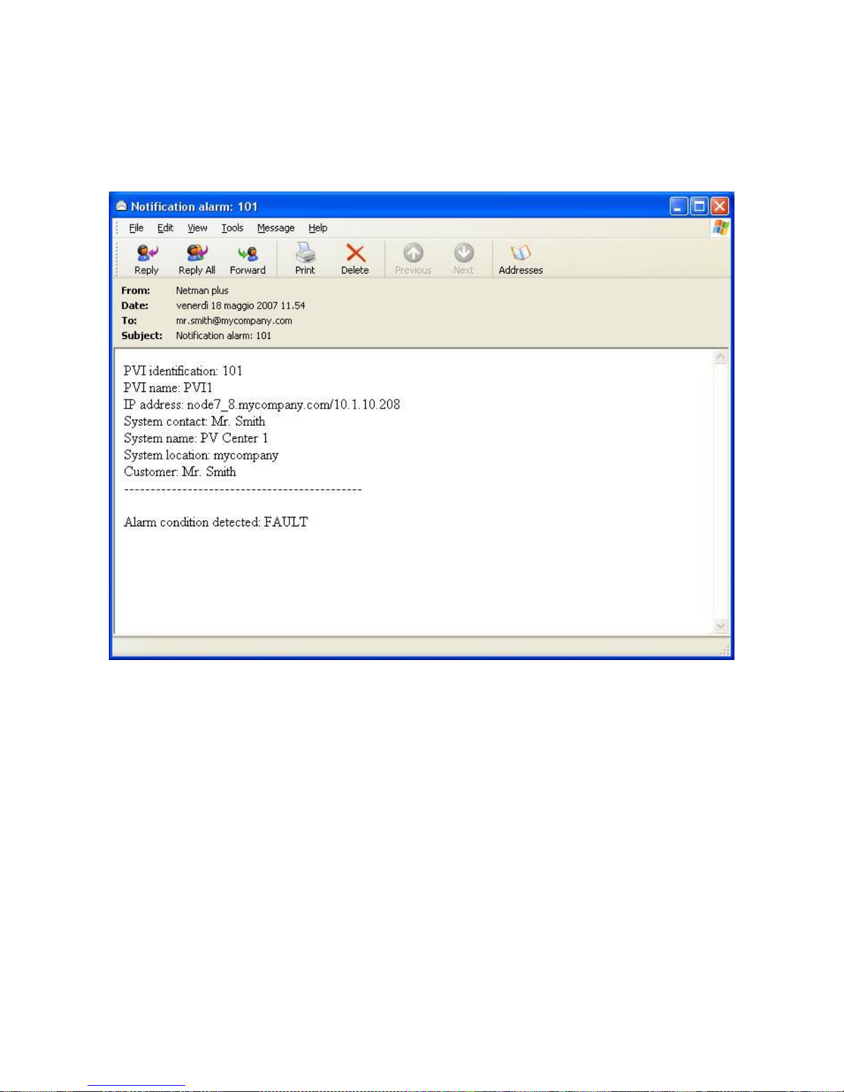
Il NetMan plus è in grado di inviare e-mail di notifica al verificarsi di una o più condizioni di allarme.
Le e-mail possono essere inviate fino a tre destinatari ed il loro invio può essere associato a tre
diversi livelli di allarme.
SMTP (Simple Mail Transfer Protocol) è il protocollo utilizzato per inoltrare le e-mail. Quest‟ultime
vengono inviate ad un server SMTP sulla porta 25. Per maggiori dettagli vedi paragrafo
“Configurazione”
Esempio di e-mail di notifica
Page 13
- ITALIANO -
- 13 -
Report
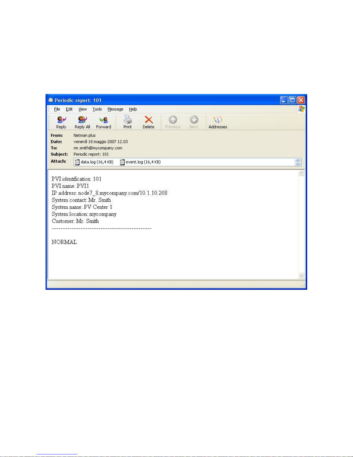
Il NetMan plus è in grado di inviare e-mail periodiche che contengono in allegato i file dell‟archivio
storico di misure ed eventi dell‟inverter.
Questo servizio può essere utilizzato per salvare periodicamente gli archivi storici.
L‟invio dei report richiede l‟abilitazione del servizio “Email”; i report vengono inviati a tutti gli indirizzi
configurati per tale servizio (per maggiori dettagli vedi paragrafo “Configurazione”).
Esempio di e-mail di report
Archivio storico di misure ed eventi dell’inverter
Il NetMan plus effettua la registrazione su archivio storico di misure (Datalog) ed eventi (Eventlog)
dell‟inverter. I dati vengono salvati su file in formato “.snv” per il Datalog e in formato testo per
l‟Eventlog. Il primo file può essere convertito in formato testo utilizzando il Software di supervisione
SunVision o l‟apposito software disponibile sul sito, I file in formato testo possono essere letti
tramite un foglio elettronico (che permette l‟ordinamento cronologico dei dati) o tramite un
qualunque editor di testi. Il formato utilizzato per la registrazione della data e ora è del tipo:
MM/DD/YY HH:MM:SS
Page 14
- ITALIANO -
- 14 -
Eventlog
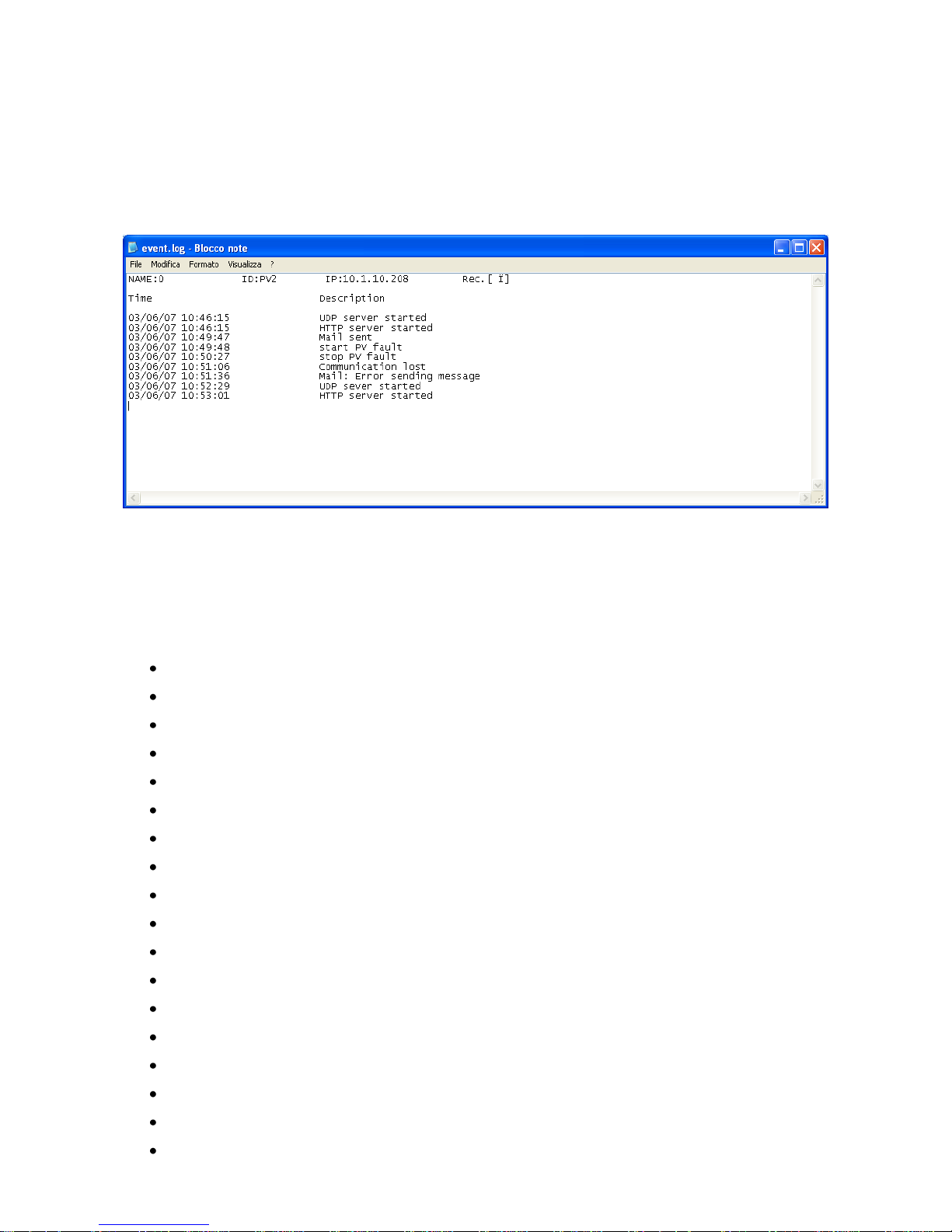
Eventlog è un servizio sempre attivo che effettua la registrazione di tutti gli eventi rilevanti
dell‟inverter sul file „event.log‟. Il file può essere scaricato via FTP o inviato tramite e-mail
utilizzando il servizio “Email report”. Il salvataggio dei dati avviene con una modalità a lista
circolare, perciò i dati più recenti vengono salvati sovrascrivendo i dati più vecchi.
Esempio di Eventlog
Datalog
Datalog è un servizio che effettua la registrazione dei principali dati dell‟inverter sul file „data.snv. Il
file può essere scaricato via FTP o può essere inviato tramite e-mail utilizzando il servizio “Email
report”. I dati monitorati sono:
Temp: Temperatura inverter
Iac1: Corrente di linea 1
Iac2: Corrente di linea 2
Iac3: Corrente di linea 3
Vac1: Tensione di linea 1
Vac2: Tensione di linea 2
Vac3: Tensione di linea 3
Fac: Frequenza di linea
Pac: Potenza d‟uscita
Zac: Impedenza di linea (solo modelli che supportano la funzione)
Etot: Energia totale prodotta
Htot: Ore totali di funzionamento
Vpv1: Tensione d‟ingresso MPPT1
Vpv2: Tensione d‟ingresso MPPT2 (se presente)
Vpv3: Tensione d‟ingresso MPPT3 (se presente)
Ipv1: Corrente in ingresso MPPT1
Ipv2: Corrente in ingresso MPPT2
Ipv3: Corrente in ingresso MPPT3
Page 15
- ITALIANO -
- 15 -
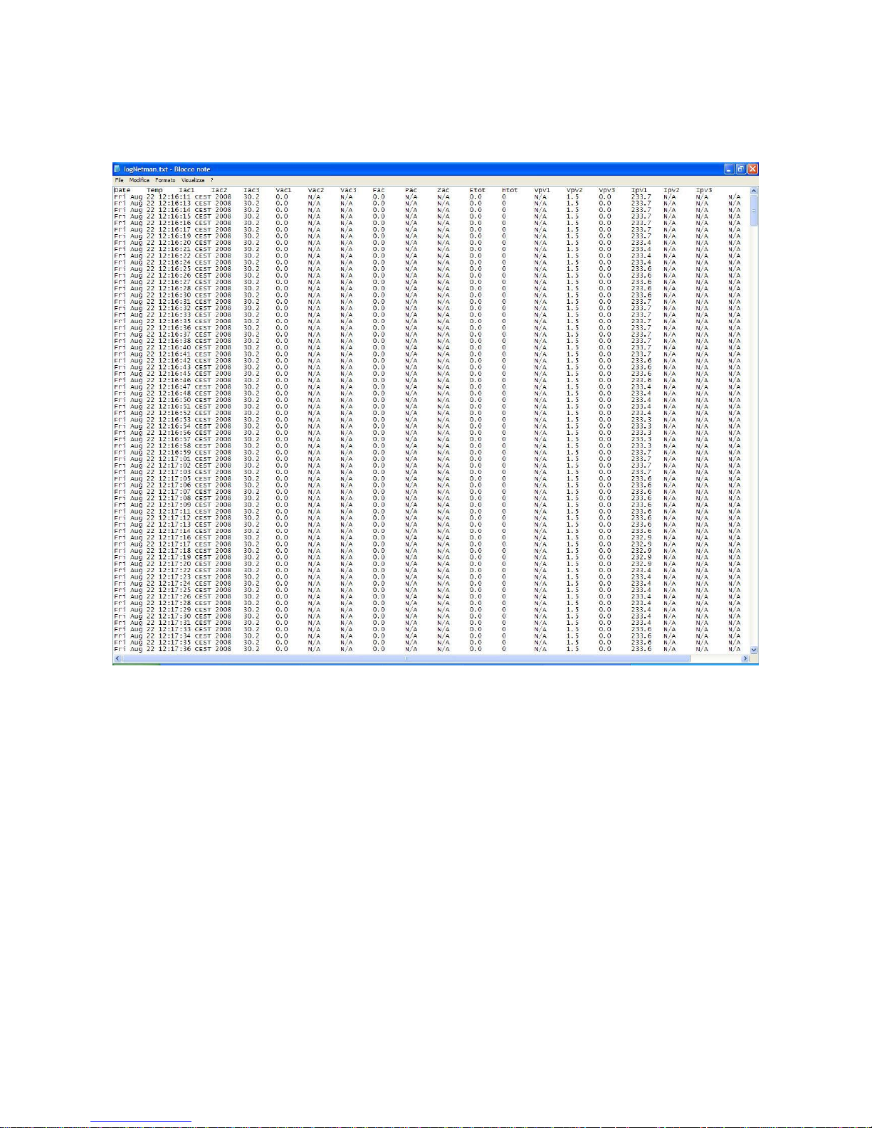
L‟intervallo di tempo tra una registrazione e la successiva (Log frequency) può essere configurato
dall‟utente (vedi paragrafo “Menù Miscellaneous”). Il salvataggio dei dati avviene con una modalità
a lista circolare, perciò i dati più recenti vengono salvati sovrascrivendo i dati più vecchi; è
possibile registrare dati riferiti ad un massimo di 1024 istanti differenti.
Esempio di Datalog
Page 16

- ITALIANO -
- 16 -
SENSORI AMBIENTALI (OPZIONALI)
È possibile collegare al NetMan plus dei sensori ambientali per monitorare temperatura, umidità ed
ingressi/uscite digitali.
Le informazioni ricavate da questi sensori possono essere visualizzate tramite il software di
monitoraggio e controllo dell‟inverter.
Sensori disponibili
Temperature: rileva la temperatura ambiente in °C.
Humidity & Temperature: rileva l‟umidità relativa in % e la temperatura ambiente in °C.
Digital I/O & Temperature: rileva la temperatura ambiente in °C e dispone di un ingresso e
di una uscita digitali.
NetMan sensor interface: trasmette i dati relativi al sensore di irraggiamento e
temperatura modulo collegato.
È possibile collegare fino a 3 sensori ambientali ad un NetMan plus (per l‟installazione
dei sensori fare riferimento al manuale degli stessi).
È necessario modificare la configurazione di default dei jumper per utilizzare i sensori.
L‟utilizzo dei sensori esclude l‟utilizzo del modem.
Page 17
- ITALIANO -
- 17 -
INSTALLAZIONE E CONFIGURAZIONE
SETTAGGIO DEI JUMPER
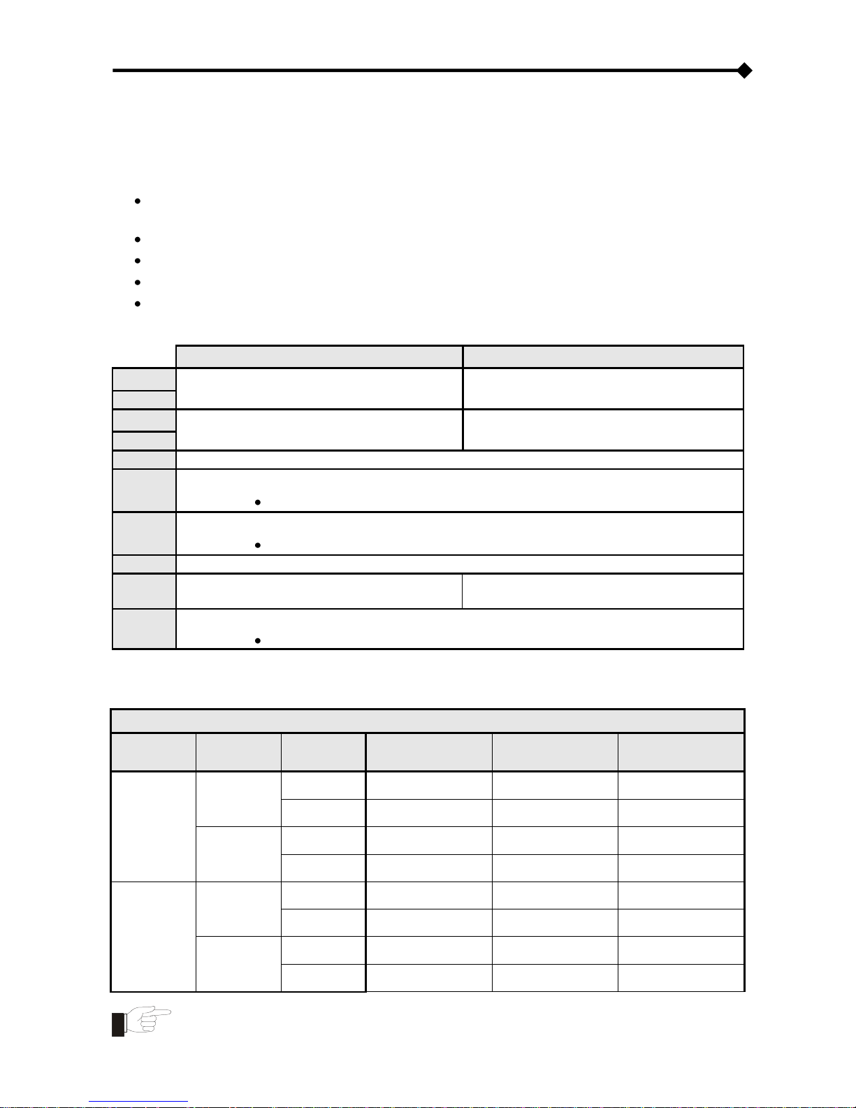
Agendo opportunamente sui jumper presenti sulla scheda è possibile:
attivare o disattivare l‟autonegoziazione della velocità e della modalità di trasmissione della
rete ethernet (JP7, JP8, JP9)
selezionare la velocità di trasmissione10/100Mbps o 10Mbps (JP7, JP8, JP9)
selezionare la modalità di trasmissione half duplex o full duplex (JP7, JP8, JP9)
attivare il netboot automatico all‟accensione (JP14)
abilitare i sensori ambientali (JP6, JP10)
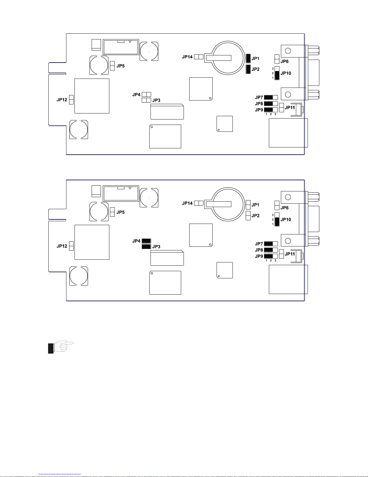
Per configurare correttamente i jumper, fare riferimento alle tabelle ed immagini seguenti.
NetMan 101 plus
NetMan 102 plus
JP1
CHIUSO
APERTO
JP2
JP3
APERTO
CHIUSO
JP4
JP5
APERTO
JP6
APERTO = SENSORI AMBIENTALI NON ABILITATI
CHIUSO = SENSORI AMBIENTALI ABILITATI
JP10
CHIUSI PIN 1-2 PER ABILITARE IL MODEM
CHIUSI PIN 2-3 PER ABILITARE I SENSORI AMBIENTALI
JP11
APERTO
JP12
APERTO
Vedere paragrafo installazione netman
102 plus
JP14
APERTO = NETBOOT AUTOMATICO DISATTIVO
CHIUSO = NETBOOT AUTOMATICO ATTIVO
(1)
(1)
Vedi paragrafo “Aggiornamento firmware”
NetMan plus
AUTO-NEG
VELOCITÀ
(Mbps)
DUPLEX
JP7
JP8
JP9
Disattivata
10
Half
chiusi PIN 2-3
chiusi PIN 2-3
chiusi PIN 2-3
Full
chiusi PIN 2-3
chiusi PIN 2-3
chiusi PIN 1-2
10/100
Half
chiusi PIN 2-3
chiusi PIN 1-2
chiusi PIN 2-3
Full
chiusi PIN 2-3
chiusi PIN 1-2
chiusi PIN 1-2
Attivata
solo 100
Half
chiusi PIN 1-2
chiusi PIN 2-3
chiusi PIN 2-3
Full
chiusi PIN 1-2
chiusi PIN 2-3
chiusi PIN 1-2
10/100
solo Half
chiusi PIN 1-2
chiusi PIN 1-2
chiusi PIN 2-3
Full o Half
chiusi PIN 1-2
chiusi PIN 1-2
chiusi PIN 1-2
le configurazioni di default sono contrassegnate dal simbolo “ ”
Page 18
- ITALIANO -
- 18 -
Configurazione di default NetMan 101 plus
Configurazione di default NetMan 102 plus
(solo per NetMan 101 plus): per agire sui jumper è necessario scollegare il
connettore di alimentazione, il cavo di rete e i cavi seriali, togliere le quattro viti
poste nella parte inferiore del dispositivo e sfilare il coperchio.
Page 19

- ITALIANO -
- 19 -
INSTALLAZIONE NETMAN 101 PLUS
1. Rimuovere la linguetta di protezione della batteria tampone.
2. Collegare la porta “UPS SERIAL” del dispositivo alla porta seriale dell‟INVERTER
utilizzando il cavo in dotazione
3. Collegare il dispositivo alla rete tramite il connettore RJ-45 (vedi “Specifiche per il cablaggio
del cavo di rete”)
4. Collegare l‟alimentatore al dispositivo
INSTALLAZIONE NETMAN 102 PLUS
Il Jumper JP12 va chiuso solo per I seguenti modelli di inverter: vedere “P/N” sulla targa dati:
HGT1151ARU
HGT1151ARU-E
HGT1151ARU-D
6PHV10K2A
6PHV10K2A-D
6PHV10K2A-INE
6PHV10K2A-IF7
HGT1151BRU
HGT1151BRU-E
HGT1151BRU-D
6PHV1K51A
6PHV1K51A-D
6PHV1K51B-INE
6PHV1K51B-IF7
HGT1201ARU
HGT1201ARU-E
HGT1201ARU-D
6PHV1K51B
6PHV1K51B-D
6PHV2K01B-INE
6PHV2K01B-IF7
HGT1201BRU
HGT1201BRU-E
HGT1201BRU-D
6PHV2K01A
6PHV2K01A-D
6PHV2K81B-INE
6PHV2K81B-IF7
HGT1281ARU
HGT1281ARU-E
HGT1281ARU-D
6PHV2K01B
6PHV2K01B-D
6PHV3K11A-INE
6PHV3K11A-IF7
HGT1281BRU
HGT1281BRU-E
HGT1281BRU-D
6PHV2K81A
6PHV2K81A-D
6PHV4K01B-INE
6PHV4K01B-IF7
HGT1311ARU
HGT1311ARU-E
HGT1311ARU-D
6PHV2K81B
6PHV2K81B-D
6PHV4K02B-INE
6PHV4K02B-IF7
HGT1401ARU
HGT1401ARU-E
HGT1401ARU-D
6PHV3K11A
6PHV3K11A-D
6PHV4K62A-INE
6PHV4K62A-IF7
HGT1401BRU
HGT1401BRU-E
HGT1401BRU-D
6PHV4K01A
6PHV4K01A-D
6PHV6K03A-INE
6PHV6K03A-IF7
HGT1402ARU
HGT1402ARU-E
HGT1402ARU-D
6PHV4K01B
6PHV4K01B-D
6PHV10K2XA-INE
6PHV10K2XA-F7
HGT1402BRU
HGT1402BRU-E
HGT1402BRU-D
6PHV4K02A
6PHV4K02A-D
6PHV1K51XA-INE
6PHV1K51XA-F7
HGT1462ARU
HGT1601ARU-E
HGT1601ARU-D
6PHV4K02B
6PHV4K02B-D
6PHV2K01XA-INE
6PHV2K01XA-F7
HGT1602ARU
HGT1601BRU-E
HGT1601BRU-D
6PHV4K62A
6PHV6K02A-D
6PHV2K81XA-INE
6PHV2K81XA-F7
HGT3102ARU
HGT1602ARU-E
HGT3102ARU-D
6PHV6K03A
6PHV6K02B-D
6PHV3K11XA-INE
6PHV3K11XA-F7
HGT1151RUXA
HGT3102ARU-E
6PHV10K2XA
6PHV6K03A-D
6PHV4K01XA-INE
6PHV4K01XA-F7
HGT1201RUXA
6PHV1K51XA
6PHV4K02XA-INE
6PHV4K02XA-F7
HGT1281RUXA
6PHV2K01XA
6PHV4K62XA-INE
6PHV4K62XA-F7
HGT1311RUXA
6PHV2K81XA
6PHV6K03XA-INE
6PHV6K03XA-F7
HGT1401RUXA
6PHV3K11XA
HGT1402RUXA
6PHV4K01XA
HGT1462RUXA
6PHV4K02XA
HGT1602RUXA
6PHV4K62XA
HGT3102RUXA
6PHV6K03XA
Procedere come segue per completare l‟installazione:
1. Rimuovere la linguetta di protezione della batteria tampone.
2. Rimuovere il coperchio dello slot di espansione dell‟INVERTER togliendo le due viti di
fissaggio
3. Inserire il NetMan 102 plus nello slot
4. Collegare il dispositivo alla rete tramite il connettore RJ-45 (vedi “Specifiche per il cablaggio
del cavo di rete”)
5. Fissare il Netman allo slot utilizzando le due viti tolte in precedenza
Page 20
- ITALIANO -
- 20 -
CONFIGURAZIONE
Il NetMan plus può essere configurato via linea seriale o via telnet.
NOTA: il NetMan plus necessita di circa 30 secondi per essere operativo dal momento in cui viene
alimentato; prima di questo tempo il dispositivo potrebbe non rispondere ai comandi che gli
vengono inviati.
Page 21

- ITALIANO -
- 21 -
Configurazione via linea seriale RS-232
Per configurare il NetMan plus via linea seriale RS-232 è necessario:
Collegare tramite il cavo null-modem in dotazione la porta “SERIAL” del dispositivo alla
porta seriale di un PC dotato di software di emulazione terminale
eseguire il software di emulazione terminale con le seguenti impostazioni: 9600 baud,
nessuna parità, 8 databits, 1 stop bit, nessun controllo di flusso
premere il tasto “ESC” del PC
alla visualizzazione del messaggio “Hit any key to login.” premere un tasto qualunque
alla richiesta di login digitare “root”
alla richiesta di password digitare la password corrente (configurazione di default:
“password”)
NOTA: durante la digitazione della password non viene visualizzato nessun carattere
Effettuato il login viene visualizzata la schermata del menù principale di configurazione. Da questa
schermata è possibile accedere ai vari menù per modificare le impostazioni del NetMan plus (vedi
paragrafo “Menù principale di configurazione” e successivi).
Configurazione via telnet
Per configurare il NetMan plus via telnet è necessario:
eseguire su un PC collegato in rete al NetMan plus un programma telnet con impostato
l‟indirizzo IP del dispositivo da configurare
alla richiesta di login digitare “root”
alla richiesta di password digitare la password corrente (configurazione di default:
“password”)
NOTA: durante la digitazione della password non viene visualizzato nessun carattere
Effettuato il login viene visualizzata la schermata del menu principale di configurazione. Da questa
schermata è possibile accedere ai vari menù per modificare le impostazioni del NetMan plus (vedi
paragrafo “Menù principale di configurazione” e successivi).
Salvataggio della configurazione e riavvio con i parametri impostati
Per rendere effettiva una nuova configurazione, è necessario salvarla sulla memoria flash; il
salvataggio provoca il riavvio del dispositivo (vedi paragrafo “Menù Save and load”).
Nota: le modifiche dell‟orologio (vedi paragrafo “Menù Time setting”) non necessitano di essere
salvate per diventare effettive.
Page 22

- ITALIANO -
- 22 -
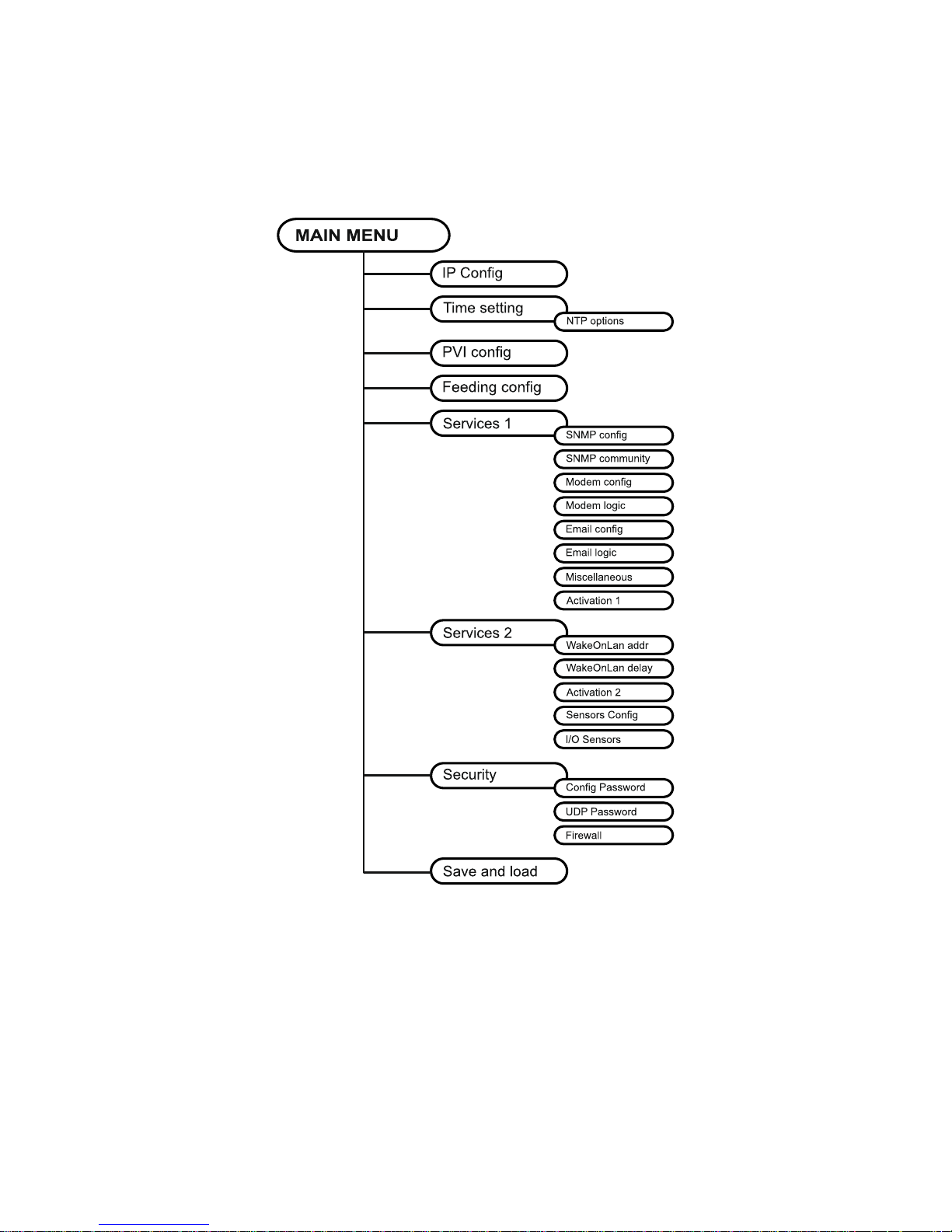
Menù principale di configurazione
Il menù principale di configurazione si presenta con una schermata simile alla seguente:
/------------------------/
/ PVI Network card /
/------------------------/
IP config......:<--
Time setting...:
PVI config.....:
Feeding config.:
Services 1. .:
Services 2. .:
Security.......:
Save and load..:
Press [Esc] to quit
Data from flash - On Line
Da questo menù principale è possibile accedere a vari sottomenù la cui funzione è illustrata nella
tabella seguente.
Menu
Funzione
IP config
Per configurare i parametri di rete
Time setting
Per configurare l‟orologio interno
PVI config
Per configurare i parametri dell‟inverter collegato
Feeding config
Per configurare i parametri di remunerazione
Services 1
Per configurare la gestione degli allarmi e dei contatori
Services 2
Security
Per configurare le password e l‟accesso alla rete
Save and load
Per salvare una configurazione e renderla quindi effettiva in
caso di riavvio del dispositivo
Page 23

- ITALIANO -
- 23 -
Per muoversi all‟interno di questo menù e dei successivi, utilizzare i tasti come descritto nella
tabella seguente; la freccia o il cursore evidenziano la selezione corrente.
Tasto
Funzione
Tasti direzionali
(Freccia sù, giù, destra, sinistra)
Per muovere il cursore all‟interno dei menù
Tab
Passa all‟opzione successiva
Invio
(1)
Scelta del sottomenù
Conferma dei caratteri digitati
Esc
(1)
Esci dal menù principale
(2)
Ritorna al menù precedente
(1)
Alcuni tasti possono avere una funzione diversa a seconda del menù.
(2)
Per uscire da un menù viene richiesta una conferma („Y‟ o „N‟) dopo aver premuto il tasto ESC.
Sulla schermata sono inoltre presenti alcuni messaggi che descrivono il tipo di dati di
configurazione visualizzati. Il significato di questi messaggi è descritto di seguito.
Data from flash: significa che la configurazione è stata caricata dalla memoria flash
Data from file: significa che la configurazione è stata caricata da file
Default data: significa che la configurazione è stata resettata a valori di default
Page 24

- ITALIANO -
- 24 -
Menù IP config
Il menù IP config si presenta con una schermata simile alla seguente.
/------------------------/
/ IP config /
/------------------------/
Hostname.......:inverter_server
IP address/DHCP:dhcp
Netmask........:
Gateway........:
Primary DNS....:
Secondary DNS..:
Mailhost.......:
Tramite questo menù è possibile impostare i principali parametri di rete come descritto nella tabella
seguente.
Campo
Parametri da inserire
Hostname
Digitare l‟host name del NetMan plus privo di spazi
IP address/DHCP
Digitare l‟indirizzo IP nel caso di IP statico; digitare “DHCP” per IP dinamico
Netmask
Digitare la netmask da usare assieme all‟indirizzo IP statico
Gateway
Digitare il nome o l‟indirizzo del gateway di rete
Primary DNS
Digitare il nome o l‟indirizzo del DNS preferito da usare
Secondary DNS
Digitare il nome o l‟indirizzo del DNS alternativo da usare
Mailhost
Digitare il nome o l‟indirizzo del server SMTP da usare per inviare e-mail.
(1)
(1)
Assicurarsi che il server SMTP accetti connessioni sulla porta 25.
NOTA: Se si assegna un indirizzo IP statico al dispositivo è necessario configurare tutti i campi con
i parametri della di rete. Se si assegna un indirizzo IP dinamico è sufficiente digitare „dhcp‟ nel
campo “IP Address/DHCP” e fornire un hostname; tutte le altre opzioni dovrebbero essere ignorate
perché vengono automaticamente configurate con DHCP.
Page 25

- ITALIANO -
- 25 -
Dopo aver premuto “ESC” e “Y” per confermare l‟uscita dal menù, viene visualizzata una
schermata che riassume i settaggi correnti (vedi immagine seguente). Premendo il tasto “Invio” si
ritorna al menù principale. È comunque necessario salvare la configurazione per renderla effettiva
in caso di riavvio del dispositivo (vedi “Menù Save and load”).
Hostname : inverter_server.mynetwork.domain
Current IPlus4 addr.: 10.1.10.187/16 (255.255.0.0) (active)
Current IPlus6 addr.: fe80:0:0:0:260:35ff:fe02:4184/64 (active)
Default IPlus4 GW : 10.1.4.1
Ethernet Address : 00:60:35:02:41:84
Primary DNS : 10.1.4.2
Secondary DNS : 10.3.4.1
DNS Timeout : 0 (ms)
DHCP Server : 10.1.5.1
DHCP Enabled : true
DHCP Lease Ends : Sun May 18 15:29:12 GMT 2007
(66 hr, 40 min, 38 seconds left)
Mailhost : mymailserver
Restore From Flash: Not Committed
Page 26

- ITALIANO -
- 26 -
Menù Time setting
/------------------------/
/ Time setting /
/------------------------/
Set time.......:<--
Set timezone...:
NTP options....:
Tramite questo menù è possibile impostare l‟ora e la data del dispositivo come descritto nella
tabella seguente.
Comando
Descrizione
Set time
Per configurare l‟ora e la data manualmente
Set timezone
Per configurare il fuso orario
NTP options
Per configurare la sincronizzare dell‟orologio con un server NTP
Premendo il tasto “Invio” in corrispondenza del comando ”Set time”, si visualizza una schermata
simile alla seguente.
Current date is Wed Jun 15 08:09:40 GMT 2005
Insert new date and clock time in this form:
MMDDYYYYHHMMSS
06152005081000
Current date is Wed Jun 15 08:10:00 GMT 2005
Digitare la data e l‟ora nel formato indicato e quindi premere il tasto invio e poi “ESC” per uscire.
Premendo il tasto “Invio” in corrispondenza del comando ”Set timezone”, si visualizza una
schermata simile alla seguente.
Current date is Thu Jun 16 12:15:25 GMT 2005
Available Timezones:
GMT (+0000) IET (-0500) CTT (+0800) VST (+0700) SST (+1100)
PST (-0800)* MST (-0700)* JST (+0900) AST (-0900)* EAT (+0300)
ECT (+0100)* NET (+0400) EET (+0200)* BET (-0300)* PLT (+0500)
PNT (-0700) IST (+0530) CST (-0600)* PRT (-0400) ACT (+0930)
MET (+0330)* ART (+0200)* AET (+1000)* AGT (-0300) MIT (-1100)
NST (+1200)* HST (-1000) CNT (-0330)* EST (-0500)* BST (+0600)
CAT (+0200)
* denotes a time zone that uses Daylight Savings
Insert new timezone:
ECT
Current date is Thu Jun 16 14:15:31 ECT 2005
Digitare il fuso orario scelto tra quelli indicati e quindi premere il tasto invio e poi “ESC” per uscire.
Page 27

- ITALIANO -
- 27 -
Menù NTP Options
/------------------------/
/ NTP options /
/------------------------/
NTP server.....:ntpserver
Sync every.....:7 days
Tramite questo menù è possibile configurare la sincronizzazione automatica dell‟orologio con un
server NTP. Dopo la configurazione, verrà automaticamente effettuata una sincronizzazione con il
server impostato. L‟ora è ricevuta nel fuso orario GMT, e può pertanto essere necessario
correggere il fuso orario corrente con il comando “Set timezone”.
Campo
Parametri da inserire
NTP Server
Digitare il nome o l‟indirizzo del server NTP
Sync every
Digitare l‟intervallo in giorni tra le sincronizzazioni
Page 28

- ITALIANO -
- 28 -
Menù PVI config
Il menù PVI config si presenta con una schermata simile alla seguente.
/------------------------/
/ PVI conf /
/------------------------/
PRTK Code......:SISER19601RU
Name...........:PV1
PVI Address....:1
Serial number..:123456
Tramite questo menù devono essere impostati i parametri dell‟inverter, come descritto nella tabella
seguente, affinché quest‟ultimo possa comunicare correttamente con il dispositivo.
Campo
Parametri da inserire
PRTK Code
SISER19601RU
Name
Digitare il nome identificativo dell‟inverter
PVI Address
Digitare l‟indirizzo dell‟inverter per la comunicazione seriale
(2)
Serial number
Digitare il codice di identificazione dell‟inverter per la connessione modem
(1)
Il codice PRTK è formato da 12 caratteri alfanumerici.
(2)
Comunicazione seriale non supportata.
Dopo aver inserito i dati e premuto il tasto “ESC” per uscire dal menù, è possibile testare i settaggi
premendo il tasto “T”. Se si effettua il test, viene visualizzata una schermata simile alla seguente
dove vengono riportate alcune tra le principali misure dell‟inverter. Se i valori rimangono a zero,
significa che l‟inverter e il dispositivo non comunicano correttamente.
/------------------------/
/ Status /
/------------------------/
PV1 voltage....: 360V
Grid Voltage...: 230V
Press [ESC] to quit
Page 29

- ITALIANO -
- 29 -
Menù Feeding config
Il menù Feeding config si presenta con una schermata simile alla seguente.
/------------------------/
/ Feeding config /
/------------------------/
Remuneration/kWh:<--
Currency........:
Weather forecast:
Not used........:
Not used........:
Not used........:
Not used........:
Not used........:
Da questo menù è possibile impostare la remunerazione per kWh di energia prodotta, la divisa e il
luogo del quale si vogliono ricercare le previsioni meteo come descritto nella tabella seguente.
Comando
Descrizione
Remuneration/kWh
Per configurare la remunerazione
Currency
Per configurare la moneta per la pagina HTML
Weather forecast
Per configurare il luogo per le previsioni del tempo
Page 30

- ITALIANO -
- 30 -
Menù Services 1
Il menù Services si presenta con una schermata simile alla seguente.
/------------------------/
/ Services /
/------------------------/
SNMP config....:<--
SNMP community.:
Modem config...:
Modem logic....:
Email config...:
Email logic....:
Miscellaneous..:
Activation 1...:
Tramite questo menù è possibile accedere alle schermate di configurazione dei vari servizi come
descritto nella tabella seguente.
Menù
Funzione
SNMP config
Per configurare il servizio SNMP (NON SUPPORTATO)
SNMP community
Modem config
Per configurare il servizio modem (NON SUPPORTATO)
Modem logic
Email config
Per configurare il servizio e-mail
Email logic
Miscellaneous
Per configurare le altre opzioni
Activation 1
Per configurare i servizi da attivare
NOTA: Per funzionare correttamente I servizi, oltre ad essere configurati, devono essere anche
attivati (vedi paragrafo “Menù Activation”). Si consiglia di attivare solo i servizi utilizzati.
Page 31

- ITALIANO -
- 31 -
Menù Email config
Il menù Email config si presenta con una schermata simile alla seguente.
/------------------------/
/ Email config /
/------------------------/
Email address 1:[email protected]
Email address 2:[email protected]
Email address 3:[email protected]
Sender address.:NetMan_plus
Customer.......:MyCustomer
Report interval:01-05:10 DD-HH:MM
User name......:User 1
Password.......:Password
Tramite questo menù è possibile configurare gli indirizzi a cui inviare le e-mail di notifica allarmi e
di report e altri parametri del servizio e-mail come descritto nella tabella seguente.
Campo
Parametri da inserire
Email address 1
Digitare gli indirizzi e-mail a cui inviare le notifiche di allarmi e i report
(vedi nota).
Email address 2
Email address 3
Sender address
Digitare l‟indirizzo da cui vengono spedite le e-mail.
(1)
Customer
Digitare una stringa identificativa; questa informazione aggiuntiva
viene inserita nella e-mail.
Report interval
Digitare il ritardo, misurato in giorni, tra l‟invio di un report e-mail e il
successivo utilizzando esattamente due cifre, seguite da una linea,
poi dall‟ora e i minuti in cui deve essere effettuato l‟invio.
User name
Se il server richiede l‟autenticazione, digitare lo “User name”
impostato
Password
Se il server richiede l‟autenticazione, digitare la Password impostata
(1)
non utilizzare il carattere “spazio” in questo campo
Dopo aver inserito i dati e premuto il tasto “ESC” per uscire dal menù, è possibile testare il
funzionamento del servizio premendo il tasto “T”. Se si effettua il test, viene visualizzata una “@” e
viene spedita una email di prova agli indirizzi configurati. Terminato l‟invio, si ritorna al menù
precedente.
NOTE:
Le e-mail di report vengono inviate a tutti gli indirizzi inseriti; per le e-mail di notifica allarmi vedi
paragrafo “Menù Email logic”.
Page 32

- ITALIANO -
- 32 -
Menù Email logic
Il menù Email logic si presenta con una schermata simile alla seguente.
/------------------------/
/ Email logic /
/------------------------/
Email 1 Email 2 Email 3 Logic:
Wait...........: X<-- 0 0 And
Fault..........: X 0 0 And
Permanent Fault: X 0 0 And
N/A............: 0 0 0 And
N/A............: 0 0 0 And
N/A............: 0 0 0 And
N/A............: 0 0 0 And
Tramite questo menù è possibile stabilire a quali indirizzi verranno inviate le e-mail al verificarsi di
determinati eventi. A ciascun evento è possibile associare uno o più indirizzi e in quest‟ultimo caso,
al verificarsi dell‟evento, le e-mail di notifica verranno inviate a tutti gli indirizzi ad esso associati.
NOTA: utilizzare il tasto INVIO per modificare la configurazione selezionata (“X” o “0”).
X: al verificarsi dell‟evento il NetMan plus invia una e-mail di notifica ai corrispondenti
indirizzi (vedi “Menù Email config” per impostare gli indirizzi);
0: al verificarsi dell‟evento il NetMan plus non invia una e-mail di notifica ai corrispondenti
indirizzi;
Nella tabella seguente viene descritto il significato degli eventi. Questi possono variare in base
all‟inverter collegato.
Evento
Significato
WAIT
Inverter in attesa di connessione alla rete
FAULT
Inverter non connesso alla rete
PERMANENT FAULT
Guasto permanente
Page 33

- ITALIANO -
- 33 -
Menù Miscellaneous
Il menù Miscellaneous si presenta con una schermata simile alla seguente.
/------------------------/
/ Miscellaneous /
/------------------------/
Log frequency..:5
UDP Port.......:33000
sysContact.....:Administrator
sysName........:My Server
sysLocation....:new building
HTTP Port......:80
Tramite questo menù è possibile configurare ulteriori parametri del dispositivo come descritto nella
tabella seguente.
Campo
Parametri da inserire
Log frequency
Digitare il ritardo, misurato in secondi, tra una registrazione dati e la
successiva (vedi paragrafo “Datalog”)
UDP Port
Digitare la porta dove il servizio UDP viene avviato.
(1)
sysContact
Digitare la stringa da associare a queste variabili SNMP
sysName
sysLocation
HTTP Port
Digitare la porta per le connessioni HTTP
(1)
Questa porta deve essere la stessa configurata nel software.
Page 34

- ITALIANO -
- 34 -
Menù Activation 1
Il menù Activation si presenta con una schermata simile alla seguente.
/------------------------/
/ Activation 1 /
/------------------------/
Enable telnet..:[ON/off]<-- Enable FTP.....:[ON/off]
Enable HTTP....:[ON/off] Enable DataLog.:[ON/off]
Enable Modem Tx:[on/OFF] Enable Modem Rx:[on/OFF]
Enable SNMP....:[on/OFF] Enable Email...:[ON/off]
Enable UDP.....:[ON/off] Enable Report..:[ON/off]
Tramite questo menù è possibile attivare o disattivare i servizi implementati nel NetMan plus:
NOTA: utilizzare il tasto INVIO per modificare la configurazione selezionata (“ON” o “OFF”).
ON (caratteri verdi): servizio attivo
OFF (caratteri rossi): servizio non attivo
Si consiglia di attivare solo i servizi utilizzati. I servizi modem e SNMP non sono supportati.
Menù Services 2
/------------------------/
/ Services 2 /
/------------------------/
WakeOnLan addr.:<--
WakeOnLan delay:
Activation.2...:
Sensors config :
I/O Sensors....:
Threshold sens.:
Tramite questo menù è possibile accedere alle schermate di configurazione di parte dei servizi
come descritto nella tabella seguente.
Menù
Funzione
WakeOnLan addr.
Per configurare il servizio Wake-on-LAN
WakeOnLan delay
Activation 2
Per attivare i servizi utilizzati
Sensors. config
Per configurare i sensori ambientali
I/O Sensors
Threshold sens
Per funzionare correttamente I servizi, oltre ad essere configurati, devono essere anche
attivati (vedi paragrafo “Menù Activation 2”). Si consiglia di attivare solo i servizi utilizzati.
Page 35

- ITALIANO -
- 35 -
Menù Wake-On-LAN address
/------------------------/
/ Wake-on-LAN address /
/------------------------/
MAC Address 1..:00-12-3F-2B-F6-6F
MAC Address 2..:aa-bb-cc-dd-ee-ff
MAC Address 3..:00-00-00-00-00-00
MAC Address 4..:
MAC Address 5..:
MAC Address 6..:
MAC Address 7..:
MAC Address 8..:
Tramite questo menù è possibile inserire fino a 8 MAC address per eseguire il Wake-on-LAN.
Assicurarsi che il proprio PC supporti tale funzione e che quest‟ultima sia
correttamente configurata
Menù Wake-On-LAN delay
/------------------------/
/ Wake-on-LAN delay /
/------------------------/
Address 1 delay:2 sec.
Address 2 delay:40 sec.
Address 3 delay:2 sec.
Address 4 delay: sec.
Address 5 delay: sec.
Address 6 delay: sec.
Address 7 delay: sec.
Address 8 delay: sec.
Tramite questo menù è possibile inserire i tempi di ritardo per ciascun Wake-on-LAN.
Page 36

- ITALIANO -
- 36 -
Menù Activation 2
/------------------------/
/ Activation 2 /
/------------------------/
Enable Serial N:[ON/off]<--
Enable Sensors.:[ON/off]
Enable WOL :[on/OFF]
Tramite questo menù è possibile attivare o disattivare alcuni dei servizi implementati nel NetMan plus:
utilizzare il tasto INVIO per modificare la configurazione selezionata (“ON” o “OFF”).
ON (caratteri verdi): servizio attivo
OFF (caratteri rossi): servizio non attivo
Si consiglia di attivare solo i servizi utilizzati.
Menù Sensors Config
Per poter accedere al menu “Sensors config” è necessario prima attivare il servizio
“Sensors” (Menù Activation 2) e salvare la configurazione (Menù Save and load).
Sensors Devices
Press [C] to change sensors, [E] to exit
Entrare nel menu “Config sensor”, collegare il primo sensore e premere “C”. Dopo alcuni istanti il
dispositivo sarà riconosciuto e gli verrà assegnato il numero che lo identifica [1]. Collegare il
sensore successivo, se presente, e premere “N”. Dopo alcuni istanti il dispositivo sarà riconosciuto
e gli verrà assegnato il numero che lo identifica [2]. Ripetere la procedura per tutti i sensori da
installare e al termine premere “Y”.
Sensors Devices
[1] Sensor Digital I/O
+ Temperature (140000009A204C28)
+ Digital I/O (220000003B8C9F12)
+ 1 Input
+ 1 Output
[2] Sensor Digital I/O
+ Temperature (510000009A154228)
+ Digital I/O (BB0000003BA2FF12)
+ 1 Input
+ 1 Output
[3] Sensor Temperature (F100000013BE0628)
+ Temperature
[4] Sensor Temperature (6C0000009F6D6128)
+ Temperature
[5] Sensor Humidity (4D00000083FF3326)
+ Humidity
+ Temperature
Press [Y] to confirm, [N] to insert a new sensor
Per un corretto funzionamento dell‟impianto, è necessario aggiungere un solo
dispositivo alla volta e attendere che venga riconosciuto dal NetMan plus.
Page 37

- ITALIANO -
- 37 -
Esempio: collegamento di un sensore Temperature, di un sensore Humidity & Temperature e di un
sensore Digital I/O & Temperature esattamente in questo ordine.
Sensors Devices
Press [C] to change sensors, [E] to exit
Collegare il primo sensore (Temperature), e premere il tasto “C”.
Sensors Devices
[1] Sensor Temperature (F100000013BE0628)
+ Temperature
Press [Y] to confirm, [N] to insert a new sensor
Attendere che il primo sensore venga identificato e quindi collegare il secondo (Humidity &
Temperature), e premere il tasto “N”.
Sensors Devices
[1] Sensor Temperature (F100000013BE0628)
+ Temperature
[2] Sensor Humidity (4D00000083FF3326)
+ Humidity
+ Temperature
Press [Y] to confirm, [N] to insert a new sensor
Attendere che anche il secondo sensore venga identificato e quindi collegare il terzo (Digital I/O &
Temperature), e premere il tasto “N”.
Sensors Devices
[1] Sensor Temperature (F100000013BE0628)
+ Temperature
[2] Sensor Humidity (4D00000083FF3326)
+ Humidity
+ Temperature
[3] Sensor Digital I/O
+ Temperature (510000009A154228)
+ Digital I/O (BB0000003BA2FF12)
+ 1 Input
+ 1 Output
Press [Y] to confirm, [N] to insert a new sensor
Premere “Y” per confermare.
Page 38

- ITALIANO -
- 38 -
Menù I/O Sensors
/------------------------/
/ Output /
/------------------------/
Wait...........: -<--
Fault..........: -
Permanent fault: -
N/A............: 4
N/A............: 3
N/A............: -
N/A............: -
Input sensor...: 1
Press [Esc] to quit
Tramite questo menù è possibile associare all‟uscita digitale dei sensori installati uno o più eventi
del PVI. L‟uscita viene chiusa al verificarsi di uno degli eventi associati.
Utilizzare il tasto INVIO per selezionare l‟uscita.
Il numero identificativo dell‟uscita è lo stesso associato al relativo sensore in fase di
installazione
Nella tabella seguente viene descritto il significato degli eventi. Questi possono variare in base al
PVI collegato.
Evento
Significato
WAIT
Inverter in attesa di connessione alla rete
FAULT
Inverte non connesso alla rete
PERMANENT FAULT
Guasto permanente
L‟evento “Input sensor ” permette di associare ad una uscita digitale l‟ingresso del sensore Digital
I/O & Temperature installato con numero identificativo più basso (il primo rilevato in fase di
installazione). Lo stato dell‟ingresso (aperto/chiuso) viene riportato all‟uscita del sensore
selezionato.
Page 39

- ITALIANO -
- 39 -
Menu Threshold sens
/------------------------/
/ Threshold sens /
/------------------------/
Temperature max:100 degree C
Temperature min:20 degree C
Temp hysteresis:5 degree C
Humidity Max...:100 % RH
Humidity Min...:0 % RH
Hum hysteresis.:5 % RH
Press [Esc] to quit
Tramite questo menù è possibile impostare le soglie di allarme per i sensori di umidità e di
temperatura. Al superamento della soglia verrà inviata una trap SNMP di allarme, e in seguito
verrà inviata una trap di allarme per ogni minuto in cui l‟allarme è attivo. L‟allarme cessa di essere
attivo quando il valore anomalo (temperatura o umidità) rientra nella soglia con il margine di
isteresi che viene configurato. (Esempio: con temperatura massima 100°C e isteresi 5°C, l‟allarme
viene attivato quando la temperatura raggiunge i 100°C e viene rimosso quando la temperatura
torna a 95°C).
Menu
Significato
Temperature max
Soglia massima di temperatura
Temperature min
Soglia minima di temperatura
Temp hysteresis
Isteresi per il rientro allarme temperatura (massima e minima)
Humidity max
Soglia massima di umidità
Humidity min
Soglia minima di umidità
Hum hysteresis
Isteresi per il rientro allarme umidità (massima e minima)
Page 40

- ITALIANO -
- 40 -
Menù Security
Il menù Security si presenta con una schermata simile alla seguente.
/------------------------/
/ Security /
/------------------------/
Config Password:<--
UDP Password...:
Firewall.......:
Da questo menù è possibile configurare la password di setup, la password UDP e il firewall come
descritto nella tabella seguente.
Menu
Funzione
Config Password
Per modificare la password utilizzata per entrare nel menù di
configurazione e per le connessioni FTP
(1)
UDP Password
Per modificare la password usata per la comunicazione UDP
(2)
Firewall
Per configurare l‟accesso dalla rete
(1)
configurazione di default: “password”.
(2)
questa password deve coincidere con quella utilizzata dal software.
Premendo il tasto INVIO in corrispondenza del comando ”Config Password”, si visualizza una
schermata simile alla seguente.
Enter the old password:
Enter the new password:
Confirm the new password:
Digitare, come richiesto, la vecchia e la nuova password.
Premendo il tasto INVIO in corrispondenza del comando ”UDP Password”, si visualizza una
schermata simile alla seguente.
Enter the new UDP password:
Confirm the new UDP password:
Digitare, come richiesto, la nuova password.
Premendo il tasto INVIO in corrispondenza del comando ”Firewall”, si visualizza una schermata
simile alla seguente.
Page 41

- ITALIANO -
- 41 -
/------------------------/
/ Firewall /
/------------------------/
Access IP 1....:*.*.*.*
Access IP 2....:0.0.0.0
Access IP 3....:0.0.0.0
Access IP 4....:0.0.0.0
Access IP 5....:0.0.0.0
Access IP 6....:0.0.0.0
Access IP 7....:0.0.0.0
Tramite questo menù è possibile configurare gli indirizzi IP o gli hostname dei dispositivi abilitati
alla comunicazione con il NetMan plus. È possibile utilizzare il carattere “*” per uno o più campi
dell‟indirizzo IP ad indicare che in quel campo sono accettati tutti i valori compresi tra 0 e 255.
Nella tabella seguente vengono riportati alcuni esempi di configurazioni possibili.
Access IP
Descrizione
*.*.*.*
Tutti i dispositivi presenti sulla rete sono abilitati a comunicare con il
NetMan plus (configurazione di default)
10.1.10.*
I dispositivi con indirizzo compreso tra 10.1.10.0 e 10.1.10.255 sono
abilitati a comunicare con il NetMan plus
myserver.mydomain
Hostname del dispositivo abilitato a comunicare con il NetMan plus
Page 42

- ITALIANO -
- 42 -
Menù Save and load
Il menù Save and load si presenta con una schermata simile alla seguente.
/------------------------/
/ Save and load /
/------------------------/
Apply changes..:<--
Revert changes.:
Load from file.:
Save to file...:
Netboot........:
Reset default..:
Tramite questo menù è possibile salvare la configurazione per renderla effettiva o caricare altre
configurazioni come descritto nella tabella seguente.
Funzione
Descrizione
Apply changes
Salva la configurazione in flash e poi riavvia automaticamente per
rendere effettive le modifiche
Revert changes
Annulla le modifiche e ricarica l‟ultima configurazione salvata (esclusa
la configurazione di rete -IP Config- e dell‟orologio –Time setting-)
Load from file
La configurazione viene caricata da file inviato via FTP
(1)
Save to file
La configurazione viene salvata su file da scaricare via FTP
(1)
Netboot
Riavvia e tenta l‟aggiornamento a una nuova versione del firmware se
disponibile sulla rete
(2)
Reset default
Carica la configurazione di default
(1)
vedi paragrafo “Configurazione di più dispositivi”
(2)
vedi paragrafo “Aggiornamento firmware”
Page 43
- ITALIANO -
- 43 -
Configurazione di più dispositivi
Nel caso si debbano installare più dispositivi che richiedano parametri di configurazioni simili, può
essere utile salvare la configurazione di base su file per poi caricarla su tutti i dispositivi da
installare. Dopo aver completato la configurazione di un dispositivo, salvarla selezionando
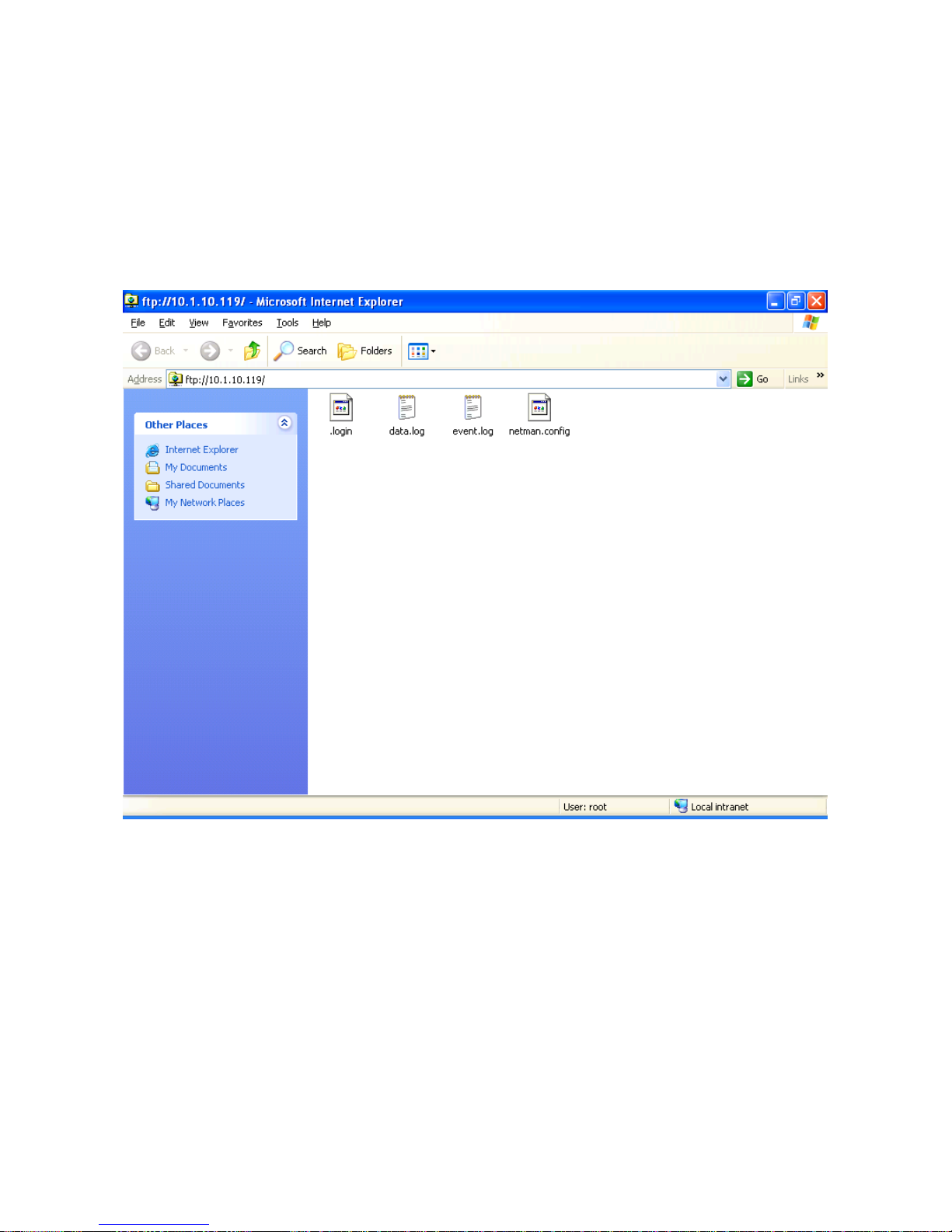
l‟opzione “Save to file” del menù Save and load (verrà creato il file “netman.config”). Il file può
essere scaricato dal dispositivo e caricato su un altro via FTP (vedi paragrafo “FTP”). Una volta
caricato il file, selezionare l‟opzione “Load from file” del menù Save and load e, se necessario,
modificare la configurazione per il nuovo dispositivo.
Esempio di connessione FTP per installazioni multiple
Page 44
- ITALIANO -
- 44 -
AGGIORNAMENTO FIRMWARE
E‟ possibile aggiornare il firmware del NetMan plus via linea seriale o via rete (Netboot).
ATTENZIONE: l‟aggiornamento del firmware provoca il reset della password corrente
(configurazione di default: “password”), la perdita delle impostazioni dell‟orologio e la cancellazione
dei file event.log e data.log.
Aggiornamento via linea seriale
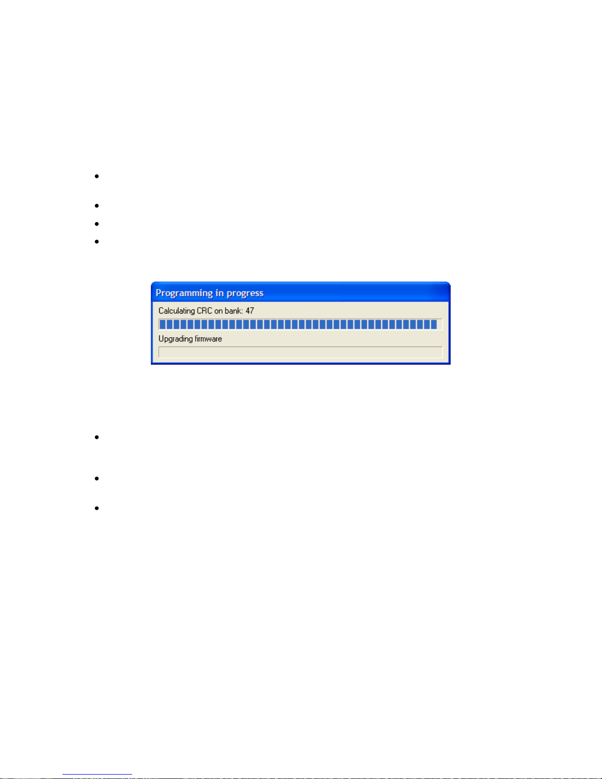
Collegare la porta “Serial” del NetMan plus alla porta seriale del PC mediante il cavo null-
modem in dotazione;
Eseguire il programma NetManplus.exe;
Selezionare la cartella contenente i file di aggiornamento;
Quando richiesto, premere il pulsante di RESET del NetMan plus. Attendere la fine
dell‟operazione.
Aggiornamento firmware via linea seriale
Aggiornamento via rete (Netboot)
Configurare e far partire il server DHCP/BOOTP. La configurazione DHCP/BOOTP deve
includere l‟indirizzo del server TFTP alla voce “next server IP” o “option 150”. Su Windows
Server per esempio è “TFTP server name” su “code 66”.
Far partire il server TFTP; su questo server deve essere presente il file di aggiornamento. Il
server TFTP deve avere l‟indirizzo configurato al passo precedente.
Avviare l‟aggiornamento in uno dei seguenti modi:
1. chiudendo il jumper JP14. Il NetMan plus avvia automaticamente il Netboot ad ogni
accensione del dispositivo;
2. inviando un comando di rete via Telnet o via UDP come descritto di seguito. Il servizio
relativo al comando utilizzato deve essere attivo;
Telnet: connettersi con utente “root” e propria password, entrare nel menù Save
and load e selezionare “Netboot”;
UDP: eseguire il comando “upgrade <ip address> -n” (dove <ip address> è
l‟indirizzo del NetMan plus). E‟ possibile impostare un gruppo di indirizzi per
l‟aggiornamento contemporaneo di più NetMan plus; ad esempio, impostando un
IP address 10.1.255.255 il comando viene inviato a tutti i dispositivi entro lo spazio
indirizzi 10.1.*.*.
3. Collegandosi alla porta seriale di configurazione e scegliendo l‟opzione “Netboot”.
Page 45
- ITALIANO -
- 45 -
DATI TECNICI
SPECIFICHE PER IL CABLAGGIO DEL CAVO DI RETE
Per collegare il dispositivo alla rete Ethernet (10Base-T) o Fast Ethernet (100Base-T) è richiesto
un cavo UTP (Unshielded Twisted Pair) o STP (Shielded Twisted Pair) con connettori RJ45. Il cavo
deve essere conforme allo standard IEEE 802.3u 100Base-T a 2 paia di cavi UTP di categoria 5 o
superiore. Il cavo tra l'adattatore e l'hub deve essere non superiore a 100m e non inferiore a 2,5m.
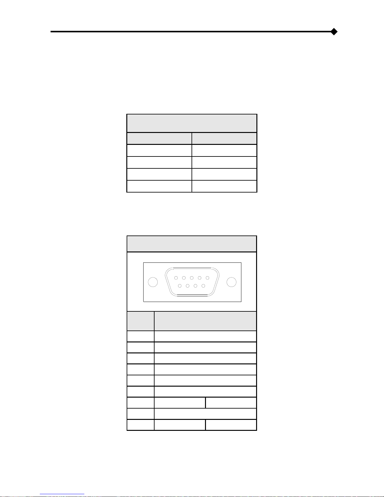
CONNESSIONI CAVO DI RETE
Segnale
Pin # to Pin #
TX+
1 1
TX-
2 2
RX+
3 3
RX-
6 6
NOTA: i pin 1 e 2 devono essere collegati ad un doppino, i pin 3 e 6 ad un altro.
SEGNALI SUL CONNETTORE “SERIAL”
SERIAL
1 2 3 4
5
6
7
8 9
PIN #
SEGNALE
1
n.c.
2
RXD
3
TXD
4
DTR
5
GND
6
n.c.
7
RTS
(1)
+5V
(2)
8 n.c.
9
n.c.
(1)
BUS sensori
(2)
n.c. = non collegato
(1)
Con jumper in configurazione di default
(2)
Con jumper in configurazione sensori ambientali abilitati
Page 46

- ITALIANO -
- 46 -
BATTERIA TAMPONE
Il dispositivo utilizza una batteria tampone per il corretto funzionamento dell‟orologio e per il
mantenimento dei dati storici in casa di mancanza di alimentazione.
In caso di lunga inattività scollegare la batteria. Si consiglia di sostituire la batteria ogni 3 anni.
Se la batteria viene sostituta, fare attenzione che il lato positivo (+) sia rivolto verso l‟alto.
Tipo di batteria: CR1620 3V Lithium
SPECIFICHE TECNICHE
NetMan plus
ALIMENTAZIONE
Tensione di ingresso
[Vdc]
12
Corrente massima di ingresso
[mA]
200
CONDIZIONI
AMBIENTALI
Temperatura operativa
[°C]
0 ÷ +40
Temperatura di immagazzinamento
[°C]
-5 ÷ +50
Umidità relativa operativa
[%]
80 (max)
Umidità relativa di immagazzinamento
[%]
90 (max)
Page 47

- 47 -
Page 48

- ENGLISH -
- 48 -
INTRODUCTION
Thank you for choosing our product.
The accessories described in this manual are of the highest quality, carefully designed and built in
order to ensure excellent performance.
This manual contains detailed instructions on how to install and use the product.
It should be kept with care near the NetMan Plus, so that it can be consulted for information
on how to use and make the most of your device. IT SHOULD BE READ BEFORE YOU
START WORKING ON THE DEVICE.
Symbols used in this manual:
Warning
Indicates important information that must not be ignored.
Information
Provides notes and useful suggestions for the User.
SAFETY
This part of the manual contains SAFETY precautions that must be followed scrupulously.
The device has been designed for professional use and is therefore not suitable for use in
the home.
The device has been designed to operate only in closed environments. It should be
installed in rooms where there are no inflammable liquids, gas or other harmful substances.
Take care that no water or liquids and/or foreign bodies fall into the device.
In the event of a fault and/or impaired operation of the device, do not attempt to repair it but
contact the authorized service centre.
The device must be used exclusively for the purpose for which it was designed. Any other
use is to be considered improper and as such dangerous. The manufacturer declines all
responsibility for damage caused by improper, wrong and unreasonable use.
Page 49

- ENGLISH -
- 49 -
ENVIRONMENTAL PROTECTION
In the development of its products, the company devotes abundant resources to analysing the
environmental aspects.
All our products pursue the objectives defined in the environmental management system
developed by the company in compliance with applicable standards.
No hazardous materials such as CFCs, HCFCs or asbestos are used in this product.
When evaluating packaging, the choice of material has been made favouring recyclable materials.
Please separate the different material of which the packaging is made and dispose of all material in
compliance with applicable standards in the country in which the product is used.
DISPOSING OF THE PRODUCT
The device contains electronic PCBs and batteries which are considered TOXIC. When the
product reaches the end of its operating life, dispose of it in accordance with applicable local
legislation.
Disposing of the product correctly contributes to respecting the environment and personal health.
© No part of this manual may be reproduced without the prior written permission of the manufacturer.
The manufacturer reserves the right to modify the product described in this manual at any time and
without notice.
Page 50

- ENGLISH -
- 50 -
SUMMARY
PRESENTATION _________________________________________________ 52
DESCRIPTION _________________________________________________________ 52
OPENING THE PACKAGING AND CHECKING THE CONTENTS _________________________ 53
NETWORK PORT _______________________________________________________ 54
RS-232 COMMUNICATION PORT ____________________________________________ 54
NETWORK SERVICES ____________________________________________________ 54
Telnet __________________________________________________________________ 54
Wake-on-Lan ____________________________________________________________ 54
HTTP ___________________________________________________________________ 55
UDP ____________________________________________________________________ 56
FTP ____________________________________________________________________ 57
Email ___________________________________________________________________ 58
Reports _________________________________________________________________ 58
INVERTER VALUES AND EVENTS HISTORY LOG ARCHIVE ____________________________ 59
Eventlog ________________________________________________________________ 59
Datalog _________________________________________________________________ 60
ENVIRONMENTAL SENSORS (OPTIONAL)_______________________________________ 62
Available sensors ________________________________________________________ 62
INSTALLATION AND CONFIGURATION ______________________________ 63
JUMPER SETTINGS ______________________________________________________ 63
INSTALLATION OF NETMAN 101 PLUS ________________________________________ 65
INSTALLATION OF NETMAN 102 PLUS ________________________________________ 65
CONFIGURATION _______________________________________________________ 66
Configuration via RS-232 serial line _________________________________________ 67
Configuration via telnet ___________________________________________________ 67
Saving the configuration and applying the changes ____________________________ 68
Page 51

- ENGLISH -
- 51 -
Main configuration menu __________________________________________________ 68
IP config menu __________________________________________________________ 70
Time setting menu _______________________________________________________ 72
NTP Options menu _______________________________________________________ 73
PVI config menu _________________________________________________________ 74
Menù Feeding config _____________________________________________________ 75
Services 1 menu _________________________________________________________ 76
Email config menu _______________________________________________________ 77
Email logic menu _________________________________________________________ 78
Miscellaneous menu ______________________________________________________ 79
Activation menu _________________________________________________________ 80
Services 2 menu _________________________________________________________ 80
Wake-On-LAN address menu _______________________________________________ 82
Wake-On-LAN delay menu _________________________________________________ 82
Activation 2 menu ________________________________________________________ 83
Sensors Config menu _____________________________________________________ 83
I/O Sensors menu ________________________________________________________ 85
Menu Threshold sens _____________________________________________________ 86
Security menu ___________________________________________________________ 87
Save and load menu ______________________________________________________ 89
Configuration of several devices ____________________________________________ 90
FIRMWARE UPDATE _____________________________________________________ 91
Update via serial line _____________________________________________________ 91
Update via network (Netboot) ______________________________________________ 91
TECHNICAL DATA ________________________________________________ 92
SPECIFICATIONS FOR THE CABLING OF THE NETWORK CABLE _______________________ 92
SIGNALS ON THE “SERIAL” CONNECTOR _____________________________________ 92
TECHNICAL SPECIFICATIONS _______________________________________________ 93
Page 52
- ENGLISH -
- 52 -
PRESENTATION
DESCRIPTION
NetMan plus is a device that allows inverter management through a LAN (Local Area Network); the
accessory supports all the main network protocols (TCP/IP, HTTP and so on) and is compatible
with Ethernet 10/100Mbps IPv4/6 networks. The inverter can therefore be integrated easily into
medium and large-sized networks.
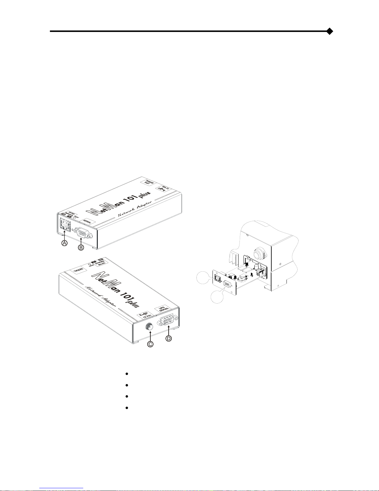
NetMan 101 plus is an accessory which is external to the inverter and connected to it by serial
cable; NetMan 102 plus is an expansion card which is inserted in the inverter slot
The device also records inverter values and events in the history log archive.
NetMan 101 plus
NetMan 102 plus
A
B
A: network port;
B: RS-232 communication port
C: power supply connector
D: connector for connection to the inverter
Page 53

- ENGLISH -
- 53 -
OPENING THE PACKAGING AND CHECKING THE CONTENTS
After opening the packaging, first check the contents.
The packaging should contain:
NetMan 101 plus
OR
NetMan 102 plus
DB9-DB9 null-modem serial cable
DB9-DB9 null-modem serial cable
12Vdc 0.3A external power supply
unit
pin to pin serial cable
Page 54

- ENGLISH -
- 54 -
NETWORK PORT
NetMan plus connects to 10/100 Mbps Ethernet networks by means of connector RJ45 (see
paragraph “Specifications for the cabling of the network cable”). The LEDs built into the connector
describe the status of the network:
Left LED:
1. on and yellow if the 10/100Mbps mode link is present
2. on and green if the 10Mbps mode link is present
Right LED:
1. on and yellow during transmission in full-duplex mode
2. on and green during transmission in half-duplex mode
RS-232 COMMUNICATION PORT
NetMan plus makes available a serial communication port through which it is possible to:
Configure NetMan plus (see paragraph “Configuration via RS-232 serial line”)
NETWORK SERVICES
NetMan plus implements a series of services based on the main network protocols. These services
can be activated or deactivated according to requirements (see paragraph “Configuration”). A brief
description for each of these is given below.
Telnet
By means of a client telnet (available on all the main operating systems) a remote connection with
NetMan plus can be established to change its configuration (see paragraph “Configuration via
telnet”).
Wake-on-Lan
NetMan plus can send “Wake-on-Lan” commands to remotely start computers.
Page 55
- ENGLISH -
- 55 -
HTTP
Using the HTTP (Hyper Text Transfer Protocol), the status of the inverter can be monitored by
means of a web browser without having to install additional software. All the most popular web
browsers (Internet Explorer, Safari, Firefox, Netscape Navigator, Konqueror, Opera) are supported.
Once the hostname or the NetMan plus IP address has been inserted in your web browser, a
screen like the one shown below will be displayed, with the main inverter operating data.
Example of display via HTTP
The following buttons are found on the left-hand side of the page:
Nominal Data: opens a page displaying the nominal values of the inverter, the list of active
alarms and the counters (see image on next page)
Telnet: opens a Telnet session (see paragraph “Telnet”)
FTP: opens an FTP session (see paragraph ”FTP”)
About: opens a page with copyright information
Meteo: opens a web page with the meteorological forecast (“see paragraph Feeding
config”)
Page 56
- ENGLISH -
- 56 -
Example of “Nominal Data” window
UDP
UDP (User Datagram Protocol) is a low level network protocol that guarantees speed in the
exchange of data and low network congestion. It is the protocol used by the SunVision software for
monitoring and control of the inverter.
The UDP connection uses the UDP 33000 port by default but can be configured on other ports
according to requirements.
Page 57
- ENGLISH -
- 57 -
FTP
FTP (File Transfer Protocol) is a network protocol used for file exchange. NetMan plus uses this
protocol for two purposes:
1. download of files of the inverter values and events history log archive (Datalog and
Eventlog)
2. download and upload of configuration files
In both cases a client FTP is required, configured with these parameters:
Host: hostname or NetMan plus IP address
User: “root”
Password: current password (default configuration: “password”)
The connection can also be established using a web browser (all the most popular web browsers
are supported), by inserting the following address: ftp://root@<address.NetMan plus>, where
<address.NetMan plus> is replaced with the device‟s real address. In this case a screen like the
following will be displayed.
Example of FTP connection
NOTE: when an FTP connection is established, all HTTP connections are refused.
Page 58
- ENGLISH -
- 58 -
Email
NetMan plus can send a notification e-mail if one or more alarm conditions occur. The e-mails can
be sent to up to three recipients and they can be sent for three different kinds of alarm.
SMTP (Simple Mail Transfer Protocol) is the protocol used to send the e-mails. They are sent to an
SMTP server on port 25. For more details, see paragraph “Configuration”
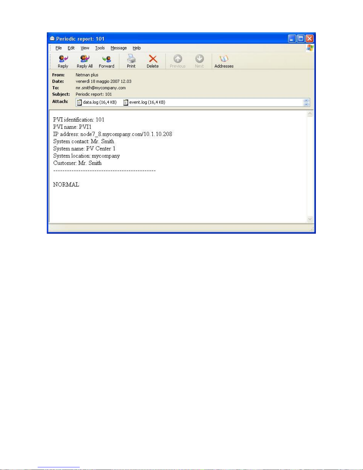
Example of notification e-mail
Reports
NetMan plus can send periodic e-mails with an attachment containing the files of the inverter
values and events history log archive.
This service can be used to periodically save the history log archives.
The “Email” service must be enabled in order to send reports; the reports are sent to all the
addresses configured for this service (for more details see paragraph “Configuration”).
Page 59
- ENGLISH -
- 59 -
Example of report e-mail
INVERTER VALUES AND EVENTS HISTORY LOG ARCHIVE
NetMan plus records the inverter values (Datalog) and events (Eventlog) in a history log archive.
The data are saved to file in “.snv” format and can be red and converted in text format using our
software SunVision o the specific conversion software, the text files can be read either by means of
an electronic spreadsheet (which allows the data to be ordered chronologically) or by any text
editor. The format used to record the date and time is of the type: MM/DD/YY HH:MM:SS
Eventlog
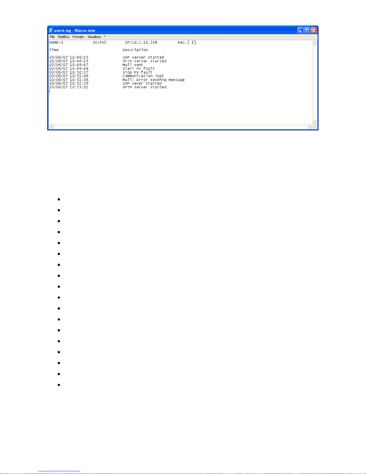
The Eventlog service is always active and records all relevant inverter events in the „event.log‟ file.
The file can be downloaded via FTP or sent by e-mail using the “Email report” service. The data
are saved in circular list mode, thus the most recent data are saved by overwriting the oldest data.
Page 60
- ENGLISH -
- 60 -
Example of Eventlog
Datalog
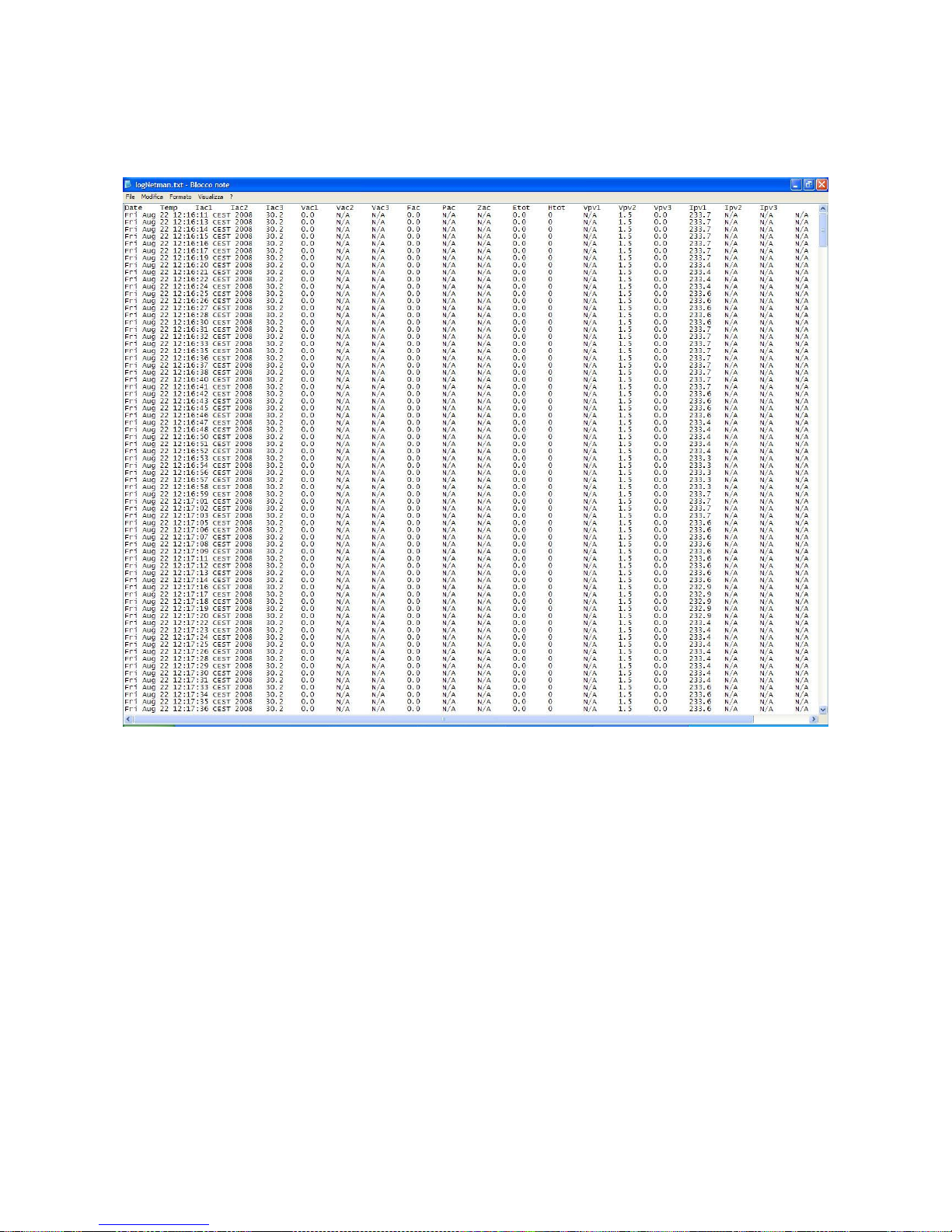
The Datalog service records the main inverter data in the „data.snv‟ file. The file can be
downloaded via FTP or can be sent by e-mail using the “Email report” service.
The following data are monitored:
Temp: Inverter Temperature
Iac1: Output current line 1
Iac2: Output current line 2
Iac3: Output current line 3
Vac1: Grid voltage 1
Vac2: Grid voltage 2
Vac3: Grid voltage 3
Fac: Grid frequency
Pac: output power
Zac: Grid impedance (only if supported)
Etot: Total energy
Htot: Total working time
Vpv1: Input voltage MPPT1
Vpv2: Input voltage MPPT2 (if embedded)
Vpv3: Input voltage MPPT3 (if embedded)
Ipv1: Input current MPPT1
Ipv2: Input current MPPT2
Ipv3: Input current MPPT3
Page 61
- ENGLISH -
- 61 -
The interval of time between one recording and the next (Log frequency) can be configured by the
user (see paragraph “Miscellaneous Menu”). The data are saved in circular list mode, thus the
most recent data are saved by overwriting the oldest data. Data for up to 1024 different points of
time can be recorded.
Example of Datalog
Page 62

- ENGLISH -
- 62 -
ENVIRONMENTAL SENSORS (OPTIONAL)
Is possibile to connect to NetMan plus the environmental sensors for monitoring temperature,
humidity and digital input/output.
The information provided by these sensors can be showed with the PVI monitoring and control
software
Available sensors
Temperature: detects the environmental temperature in °C.
Humidity & Temperature: detects the relative humidity in % and the environmental
temperature in °C.
Digital I/O & Temperature: detects the environmental temperature in °C and features a
digital input and a digital output.
NetMan sensor interface: transmits the data measured by the connected irradiance and
module temperature sensor to the monitoring software.
It is possible to connect up to 3 environmental sensor to a NetMan plus (for sensor
installation please see the sensors‟ manual)
It is necessary to modify the default jumper configuration for using the sensors. The
use of the sensors does not allow the use of the modem
Page 63
- ENGLISH -
- 63 -
INSTALLATION AND CONFIGURATION
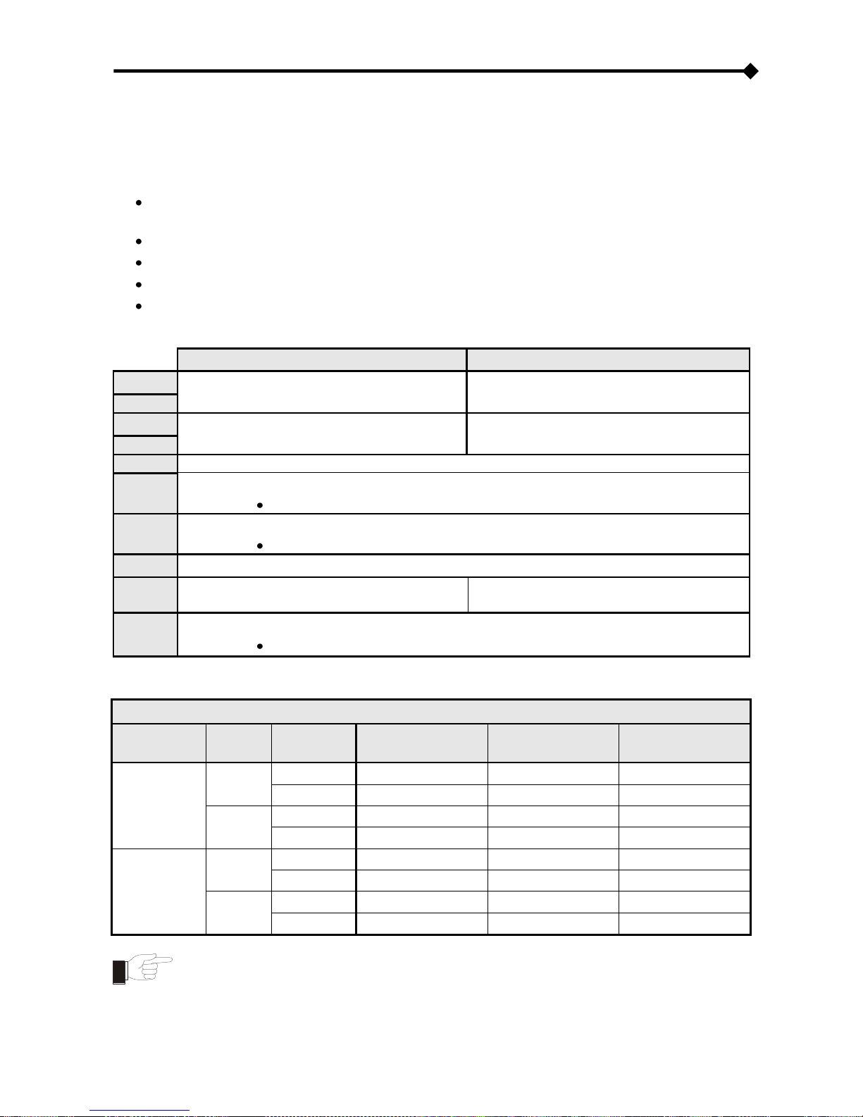
JUMPER SETTINGS
The jumpers on the card can be used to:
activate or deactivate the autonegotiation of transmission speed and mode of the Ethernet
network (JP7, JP8, JP9)
select 10/100Mbps or 10Mbps transmission speed (JP7, JP8, JP9)
select half duplex or full duplex transmission mode (JP7, JP8, JP9)
activate automatic netboot on start-up (JP14)
enable the environmental sensors (JP6, JP10)
Refer to the tables and figures below to configure the jumpers correctly.
NetMan 101 plus
NetMan 102 plus
JP1
CLOSED
OPEN
JP2
JP3
OPEN
CLOSED
JP4
JP5
OPEN
JP6
OPEN = DISABLE ENVIRONMENTAL SENSORS
CLOSED = ACTIVATE ENVIRONMENTAL SENSORS
JP10
CLOSED 1-2 TO ENABLE THE MODEM
CLOSED 2-3 TO ENABLE THE ENVIRONMENTAL SENSORS
JP11
OPEN
JP12
OPEN
See paragraph INSTALLATION OF
NETMAN 102 PLUS
JP14
OPEN = AUTOMATIC NETBOOT INACTIVE
CLOSED = AUTOMATIC NETBOOT ACTIVE
(1)
(1)
See paragraph “Firmware update”
NetMan plus
AUTO-NEG
SPEED
(Mbps)
DUPLEX
JP7
JP8
JP9
Deactivated
10
Half
PINS 2-3 closed
PINS 2-3 closed
PINS 2-3 closed
Full
PINS 2-3 closed
PINS 2-3 closed
PINS 1-2 closed
10/100
Half
PINS 2-3 closed
PINS 1-2 closed
PINS 2-3 closed
Full
PINS 2-3 closed
PINS 1-2 closed
PINS 1-2 closed
Activated
only 100
Half
PINS 1-2 closed
PINS 2-3 closed
PINS 2-3 closed
Full
PINS 1-2 closed
PINS 2-3 closed
PINS 1-2 closed
10/100
only Half
PINS 1-2 closed
PINS 1-2 closed
PINS 2-3 closed
Full or Half
PINS 1-2 closed
PINS 1-2 closed
PINS 1-2 closed
The default configurations are shown with the symbol “ ”.
Page 64
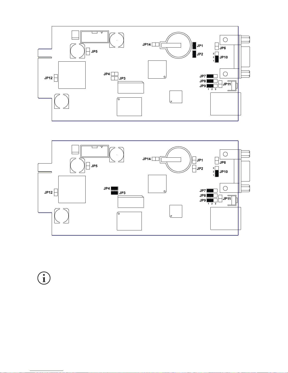
- ENGLISH -
- 64 -
NetMan 101 plus default configuration
NetMan 102 plus default configuration
(only for NetMan 101 plus): In order to set the jumpers, first disconnect the power
supply connector, the network cable and the serial cables and then remove the four
screws located in the lower part of the device and take off the cover.
Page 65

- ENGLISH -
- 65 -
INSTALLATION OF NETMAN 101 PLUS
1. Remove the protection strip of the backup battery.
2. Connect the “UPS SERIAL” port of the device to the serial port of the inverter using the
cable supplied.
3. Connect the device to the network by means of connector RJ-45 (see “Specifications for
the cabling of the network cable”)
4. Connect the power supply unit to the device.
INSTALLATION OF NETMAN 102 PLUS
The jumper JP12 must be closed for the following inverter: see “P/N” field on the rating label
HGT1151ARU
HGT1151ARU-E
HGT1151ARU-D
6PHV10K2A
6PHV10K2A-D
6PHV10K2A-INE
6PHV10K2A-IF7
HGT1151BRU
HGT1151BRU-E
HGT1151BRU-D
6PHV1K51A
6PHV1K51A-D
6PHV1K51B-INE
6PHV1K51B-IF7
HGT1201ARU
HGT1201ARU-E
HGT1201ARU-D
6PHV1K51B
6PHV1K51B-D
6PHV2K01B-INE
6PHV2K01B-IF7
HGT1201BRU
HGT1201BRU-E
HGT1201BRU-D
6PHV2K01A
6PHV2K01A-D
6PHV2K81B-INE
6PHV2K81B-IF7
HGT1281ARU
HGT1281ARU-E
HGT1281ARU-D
6PHV2K01B
6PHV2K01B-D
6PHV3K11A-INE
6PHV3K11A-IF7
HGT1281BRU
HGT1281BRU-E
HGT1281BRU-D
6PHV2K81A
6PHV2K81A-D
6PHV4K01B-INE
6PHV4K01B-IF7
HGT1311ARU
HGT1311ARU-E
HGT1311ARU-D
6PHV2K81B
6PHV2K81B-D
6PHV4K02B-INE
6PHV4K02B-IF7
HGT1401ARU
HGT1401ARU-E
HGT1401ARU-D
6PHV3K11A
6PHV3K11A-D
6PHV4K62A-INE
6PHV4K62A-IF7
HGT1401BRU
HGT1401BRU-E
HGT1401BRU-D
6PHV4K01A
6PHV4K01A-D
6PHV6K03A-INE
6PHV6K03A-IF7
HGT1402ARU
HGT1402ARU-E
HGT1402ARU-D
6PHV4K01B
6PHV4K01B-D
6PHV10K2XA-INE
6PHV10K2XA-F7
HGT1402BRU
HGT1402BRU-E
HGT1402BRU-D
6PHV4K02A
6PHV4K02A-D
6PHV1K51XA-INE
6PHV1K51XA-F7
HGT1462ARU
HGT1601ARU-E
HGT1601ARU-D
6PHV4K02B
6PHV4K02B-D
6PHV2K01XA-INE
6PHV2K01XA-F7
HGT1602ARU
HGT1601BRU-E
HGT1601BRU-D
6PHV4K62A
6PHV6K02A-D
6PHV2K81XA-INE
6PHV2K81XA-F7
HGT3102ARU
HGT1602ARU-E
HGT3102ARU-D
6PHV6K03A
6PHV6K02B-D
6PHV3K11XA-INE
6PHV3K11XA-F7
HGT1151RUXA
HGT3102ARU-E
6PHV10K2XA
6PHV6K03A-D
6PHV4K01XA-INE
6PHV4K01XA-F7
HGT1201RUXA
6PHV1K51XA
6PHV4K02XA-INE
6PHV4K02XA-F7
HGT1281RUXA
6PHV2K01XA
6PHV4K62XA-INE
6PHV4K62XA-F7
HGT1311RUXA
6PHV2K81XA
6PHV6K03XA-INE
6PHV6K03XA-F7
HGT1401RUXA
6PHV3K11XA
HGT1402RUXA
6PHV4K01XA
HGT1462RUXA
6PHV4K02XA
HGT1602RUXA
6PHV4K62XA
HGT3102RUXA
6PHV6K03XA
Complete the installation proceeding as follows:
1. Remove the protection strip of the backup battery.
2. Remove the cover of the UPS expansion slot by removing the two retaining screws.
3. Insert NetMan 102 plus in the slot.
4. Connect the device to the network by means of connector RJ-45 (see “Specifications for
the cabling of the network cable”)
5. Secure Netman in the slot using the two screws removed previously.
Page 66
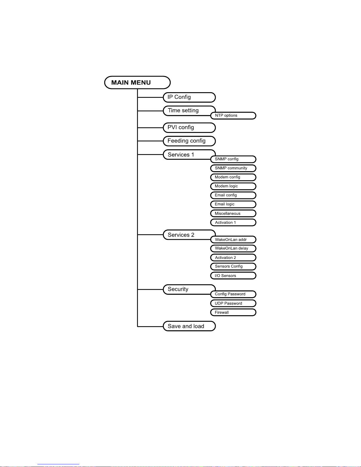
- ENGLISH -
- 66 -
CONFIGURATION
NetMan plus can be configured via serial line or via telnet.
NOTE: NetMan plus needs approx. 30 seconds to become operational from when it is powered up;
before this time the device may not respond to commands that are sent to it.
Page 67

- ENGLISH -
- 67 -
Configuration via RS-232 serial line
To configure NetMan plus via RS-232 serial line, it is necessary to:
Connect, with the null-modem cable provided, the “SERIAL” port of the device to the serial
port of a PC with terminal emulation software
execute the terminal emulation software with the following settings: 9600 baud, no parity, 8
databits, 1 stop bit, no flow control
press the “ESC” key of the PC
when the message “Hit any key to login.” is displayed, press any key
at the login prompt, enter “root”
at the password prompt, enter the current password (default configuration: “password”)
NOTE: During password’s typing, no character is shown.
Once login has been effected, the screen of the main configuration menu is displayed. From this
screen it is possible to access the various menus to change NetMan plus settings (see paragraph
“Main configuration menu” and following paragraphs).
Configuration via telnet
To configure NetMan plus via telnet it is necessary to:
execute a telnet program on a PC connected in a network to NetMan plus set with the IP
address of the device to be configured
at the login prompt, enter “root”
at the password prompt, enter the current password (default configuration: “password”)
NOTE: During password’s typing, no character is shown.
Once login has been effected, the screen of the main configuration menu is displayed. From this
screen it is possible to access the various menus to change NetMan plus settings (see paragraph
“Main configuration menu” and following paragraphs).
Page 68

- ENGLISH -
- 68 -
Saving the configuration and applying the changes
In order to make the new configuration effective, it is necessary to save it in the flash memory; this
action automatically reboot the device (see paragraph “Menu Save and load”).
Note: the clock settings (see paragraph “Time settings Menu”) become effective without saving
Main configuration menu
The main configuration menu displays a screen like the following:
/------------------------/
/ PVI Network card /
/------------------------/
IP config......:<--
Time setting...:
PVI config.....:
Feeding config.:
Services 1... .:
Services 2... .:
Security.......:
Save and load..:
Press [Esc] to quit
Data from flash - On Line
Page 69

- ENGLISH -
- 69 -
From this main menu it is possible to access the various submenus, the function of each of which
is shown in the table below.
Menu
Function
IP config
To configure the network parameters
Time setting
To configure the internal clock
PVI config
To configure the type of inverter connected
Feeding config
To configure the remuneration parameters
Services 1
To activate and/or deactivate device services
Services 2
Security
To configure the password and access to the network
Save and load
To save a configuration thus making it effective in the event
of a device restart
To move within this menu and the following menus, use the keys as described in the following
table; the arrow or the cursor shows the current selection.
Key
Function
Direction keys
(Arrow up, down, right, left)
To move the cursor within the menus
Tab
Goes on to next option
Enter
(1)
Choice of submenu
Confirmation of characters entered
Esc
(1)
Exit main menu
(2)
Return to previous menu
(1)
Some keys can have a different function depending on the menu.
(2)
To exit from a menu a confirmation („Y‟ or „N‟) is required after pressing the ESC key.
The screen also displays some messages describing the kind of configuration data displayed. The
meaning of these messages is described below.
Data from flash: means that the configuration has been loaded from the flash memory
Data from file: means that the configuration has been loaded from file
Default data: means that the configuration has been reset to the default values
Page 70

- ENGLISH -
- 70 -
IP config menu
The IP config menu shows a screen like the one below.
/------------------------/
/ IP config /
/------------------------/
Hostname.......:inverter_server
IP address/DHCP:dhcp
Netmask........:
Gateway........:
Primary DNS....:
Secondary DNS..:
Mailhost.......:
With this menu the main network parameters can be set as described in the following table.
Field
Parameters to be inserted
Hostname
Enter the NetMan plus host name without blank spaces
IP address/DHCP
Enter the IP address for a static IP; enter “DHCP” for a dynamic IP
Netmask
Enter the netmask to be used together with the static IP address
Gateway
Enter the name or the address of the network gateway
Primary DNS
Enter the name or the address of the preferred DNS to be used
Secondary DNS
Enter the name or the address of the alternative DNS to be used
Mailhost
Enter the name or the address of the SMTP server to be used to send emails.
(1)
(1)
Ensure that the SMTP server accepts connections on port 25.
Page 71

- ENGLISH -
- 71 -
NOTE: If a static IP address is assigned to the device, all the fields must be configured with the
network parameters. If a dynamic IP address is assigned, just enter „dhcp‟ in the “IP
Address/DHCP” field and provide a hostname; all the other options should be ignored because
these are automatically configured with DHCP.
After pressing “ESC” and “Y” to confirm exit from the menu, a screen is displayed summarizing the
current settings (see image below). Press the “ENTER” key to return to the main menu. The
configuration must however be saved to make it effective in the event of a restart of the device
(see “Save and load” menu).
Hostname : inverter_server.mynetwork.domain
Current IPlus4 addr.: 10.1.10.187/16 (255.255.0.0) (active)
Current IPlus6 addr.: fe80:0:0:0:260:35ff:fe02:4184/64 (active)
Default IPlus4 GW : 10.1.4.1
Ethernet Address : 00:60:35:02:41:84
Primary DNS : 10.1.4.2
Secondary DNS : 10.3.4.1
DNS Timeout : 0 (ms)
DHCP Server : 10.1.5.1
DHCP Enabled : true
DHCP Lease Ends : Sun May 18 15:29:12 GMT 2007
(66 hr, 40 min, 38 seconds left)
Mailhost : mymailserver
Restore From Flash: Not Committed
Page 72

- ENGLISH -
- 72 -
Time setting menu
/------------------------/
/ Time setting /
/------------------------/
Set time.......:<--
Set timezone...:
NTP options....:
From this menu the time and date of the device can be set as described in the following table.
Command
Description
Set time
To configure the time and date manually
Set timezone
To configure the time zone
NTP options
To configure clock synchronization with an NTP server
Pressing the “ENTER” key corresponding to the “Set time” command displays a screen like the one
shown below.
Current date is Wed Jun 15 08:09:40 GMT 2005
Insert new date and clock time in this form:
MMDDYYYYHHMMSS
06152005081000
Current date is Wed Jun 15 08:10:00 GMT 2005
Enter the date and time in the format shown, then press the ENTER key and then “ESC” to exit.
Pressing the “ENTER” key corresponding to the “Set timezone” command displays a screen like
the one shown below.
Current date is Thu Jun 16 12:15:25 GMT 2005
Available Timezones:
GMT (+0000) IET (-0500) CTT (+0800) VST (+0700) SST (+1100)
PST (-0800)* MST (-0700)* JST (+0900) AST (-0900)* EAT (+0300)
ECT (+0100)* NET (+0400) EET (+0200)* BET (-0300)* PLT (+0500)
PNT (-0700) IST (+0530) CST (-0600)* PRT (-0400) ACT (+0930)
MET (+0330)* ART (+0200)* AET (+1000)* AGT (-0300) MIT (-1100)
NST (+1200)* HST (-1000) CNT (-0330)* EST (-0500)* BST (+0600)
CAT (+0200)
* denotes a time zone that uses Daylight Savings
Insert new timezone:
ECT
Current date is Thu Jun 16 14:15:31 ECT 2005
Enter the time zone selected from those shown, then press the ENTER key and then “ESC” to exit.
Page 73

- ENGLISH -
- 73 -
NTP Options menu
/------------------------/
/ NTP options /
/------------------------/
NTP server.....:ntpserver
Sync every.....:7 days
With this menu is possible to configure the scheduled clock synchronization with a NTP server.
After the configuration, will be performer a synchronization with the server. The time is received
with the GMT time zone, thus it may be necessary to correct the current time zone with the “Set
timezone” command.
Campo
Parametri da inserire
NTP Server
Insert name or IP address for NTP server
Sync every
Insert the days interval between synchronizations
Page 74

- ENGLISH -
- 74 -
PVI config menu
The PVI config menu shows a screen like the one below.
/------------------------/
/ PVI conf /
/------------------------/
PRTK Code......:SISER19601RU
Name...........:PV1
PVI Address....:1
Serial number..:123456
With this menu the inverter parameters must be set as described in the following table, for the
inverter to be able to communicate correctly with the device.
Field
Parameters to be inserted
PRTK Code
SISER19601RU
Name
Enter the identifying name of the inverter
PVI Address
Enter the inverter address for serial communication
(2)
Serial number
Enter the inverter identification code for modem connection
(1)
The PRTK code is formed of 12 alphanumeric characters.
(2)
The serial communication is not supported.
After inserting the data and pressing the “ESC” key to exit from the menu, the settings can be
tested by pressing the “T” key. If the test is performed, a screen like the one shown below is
displayed, with some of the main inverter values. If the values remain at zero, this means that the
inverter and the device are not communicating correctly.
/------------------------/
/ Status /
/------------------------/
PV1 voltage....: 360V
Grid Voltage...: 230V
Press [ESC] to quit
Page 75

- ENGLISH -
- 75 -
Menù Feeding config
The Feeding config menu shows a screen like the one below.
/------------------------/
/ Feeding config /
/------------------------/
Remuneration/kWh:<--
Currency........:
Weather forecast:
Not used........:
Not used........:
Not used........:
Not used........:
Not used........:
With this menu the feeding parameters must be set as described in the following table.
Comando
Descrizione
Remuneration/kWh
To configure the remuneration coefficient
Currency
To configure the currency for the HTML page
Weather forecast
To configure the place for meteorological forecast
Page 76

- ENGLISH -
- 76 -
Services 1 menu
The Services menu shows a screen like the one below.
/------------------------/
/ Services /
/------------------------/
SNMP config....:<--
SNMP community.:
Modem config...:
Modem logic....:
Email config...:
Email logic....:
Miscellaneous..:
Activation 1...:
With this menu the configuration screens of the various services can be accessed as described in
the following table.
Menu
Function
SNMP config
To configure the SNMP service (NOT SUPPORTED)
SNMP community
Modem config
To configure the modem service (NOT SUPPORTED)
Modem logic
Email config
To configure the e-mail service
Email logic
Miscellaneous
To configure the other options
Activation 1
To configure the services to be activated
NOTE: as well as being configured, the services must also be activated to function correctly (see
paragraph “Activation menu”). It is recommended to activate only the services used.
Page 77

- ENGLISH -
- 77 -
Email config menu
The Email config menu shows a screen like the one below.
/------------------------/
/ Email config /
/------------------------/
Email address 1:[email protected]
Email address 2:[email protected]
Email address 3:[email protected]
Sender address.:NetMan_plus
Customer.......:MyCustomer
Report interval:01-05:10 DD-HH:MM
User name......:User 1
Password.......:Password
This menu may be used to configure the addresses to which to send the alarm notification and
report e-mails and other parameters of the e-mail service as described in the following table.
Field
Parameters to be inserted
Email address 1
Enter the e-mail addresses to which to send the alarm notifications
and reports (see note).
Email address 2
Email address 3
Sender address
Enter the address from which the e-mails are sent.
(1)
Customer
Enter an identifying string; this additional information is included in
the e-mail.
Report interval
Enter the delay, measured in days, between the sending of one
report e-mail and the next by using exactly 2 figures, followed by a
line, an finally by the hour and minutes on which the email should be
sent.
User name
If the server requires authentication, enter the required user name
Password
If the server requires authentication, enter the required password
(1)
do not use the “space” character in this field
After inserting the data and pressing the “ESC” key to exit from the menu, the service can be
tested by pressing the “T” key. If the test is performed, a “@” is displayed and a test email is sent
to all the configured email addresses. After this the previous menu is shown.
NOTE:
Report e-mails are sent to all the addresses inserted; for alarm notification e-mails see
paragraph “Email logic menu”.
Page 78

- ENGLISH -
- 78 -
Email logic menu
The Email logic menu shows a screen like the one below.
/------------------------/
/ Email logic /
/------------------------/
Email 1 Email 2 Email 3 Logic:
Wait...........: X<-- 0 0 And
Fault..........: X 0 0 And
Permanent Fault: X 0 0 And
N/A............: 0 0 0 And
N/A............: 0 0 0 And
N/A............: 0 0 0 And
N/A............: 0 0 0 And
With this menu it can be established to which addresses the e-mails will be sent when certain
events occurs. One or more addresses can be associated with each event and in the latter case,
when the event occurs, notification e-mails will be sent to all the addresses associated with it.
NOTE: use the ENTER key to change the selected configuration (“X” or “0”).
X: when the event occurs, NetMan plus sends a notification e-mail to the corresponding
addresses (see “Email logic menu” to set the addresses);
0: when the event occurs, NetMan plus does not send a notification e-mail to the
corresponding addresses;
The following table describes the meaning of the events. These can vary depending on the inverter
connected.
Event
Meaning
WAIT
The inverter is waiting the connection to the grid
FAULT
The inverter is not connected to the grid
PERMANENT FAULT
Failure of the inverter
Page 79

- ENGLISH -
- 79 -
Miscellaneous menu
The Miscellaneous configuration menu shows a screen like the one below.
/------------------------/
/ Miscellaneous /
/------------------------/
Log frequency..:5
UDP Port.......:33000
sysContact.....:Administrator
sysName........:My Server
sysLocation....:new building
HTTP Port......:80
With this menu further device parameters can be configured as described in the following table.
Field
Parameters to be inserted
Log frequency
Enter the delay, measured in seconds, between one data log and the next
(see paragraph “Datalog”)
UDP Port
Enter the port where the UDP service is started
(1)
sysContact
Enter the string to be associated with these SNMP variables
sysName
sysLocation
HTTP Port
Enter the port for HTTP connection
(1)
This port must be the same as configured in the software.
Page 80

- ENGLISH -
- 80 -
Activation menu
The Activation menu shows a screen like the one below.
/------------------------/
/ Activation /
/------------------------/
Enable telnet..:[ON/off]<-- Enable FTP.....:[ON/off]
Enable HTTP....:[ON/off] Enable DataLog.:[ON/off]
Enable Modem Tx:[on/OFF] Enable Modem Rx:[on/OFF]
Enable SNMP....:[on/OFF] Enable Email...:[ON/off]
Enable UDP.....:[ON/off] Enable Report..:[ON/off]
With this menu the services implemented in NetMan plus can be activated or deactivated:
NOTE: use the ENTER key to change the selected configuration (“ON” or “OFF”).
ON (green characters): service active
OFF (red characters): service not active
It is recommended to activate only the services used. The SNMP and Modem services are not
supported.
Services 2 menu
/------------------------/
/ Services 2 /
/------------------------/
WakeOnLan addr.:<--
WakeOnLan delay:
Activation.2...:
Sensors config :
I/O Sensors....:
Threshold sens.:
With this menu the configuration screens of the various services can be accessed as described in
the following table.
Menù
Funzione
WakeOnLan addr.
To configure the Wake-on-LAN service
WakeOnLan delay
Activation 2
To configure the services to be activated
Sensors. config
To configure the environmental sensors
I/O Sensors
Threshold sens
Page 81

- ENGLISH -
- 81 -
as well as being configured, the services must also be activated to function correctly (see
paragraph “Activation 2 menu”). It is recommended to activate only the services used.
Page 82

- ENGLISH -
- 82 -
Wake-On-LAN address menu
/------------------------/
/ Wake-on-LAN address /
/------------------------/
MAC Address 1..:00-12-3F-2B-F6-6F
MAC Address 2..:aa-bb-cc-dd-ee-ff
MAC Address 3..:00-00-00-00-00-00
MAC Address 4..:
MAC Address 5..:
MAC Address 6..:
MAC Address 7..:
MAC Address 8..:
With this menu is possible to insert up to 8 MAC address to execute Wake-on-LAN.
Please make sure that your PC supports this function, and that it is correctly
configured
Wake-On-LAN delay menu
/------------------------/
/ Wake-on-LAN delay /
/------------------------/
Address 1 delay:2 sec.
Address 2 delay:40 sec.
Address 3 delay:2 sec.
Address 4 delay: sec.
Address 5 delay: sec.
Address 6 delay: sec.
Address 7 delay: sec.
Address 8 delay: sec.
With this menu is possible to insert the delay times for each Wake-on-LAN.
Page 83

- ENGLISH -
- 83 -
Activation 2 menu
/------------------------/
/ Activation 2 /
/------------------------/
Enable Serial N:[ON/off]<--
Enable Sensors.:[ON/off]
Enable WOL :[on/OFF]
With this menu the services implemented in NetMan plus can be activated or deactivated:
use the ENTER key to change the selected configuration (“ON” or “OFF”).
ON (green characters): service active
OFF (red characters): service not active
It is recommended to activate only the services used.
Sensors Config menu
To enter on the “Sensors config” menu is necessary to enable the “Sensors” service
(Activation 2 menu) and to save the configuration (Save and load menu).
Sensors Devices
Press [C] to change sensors, [E] to exit
Enter on the “Config sensor” menu, connect the first sensor and press “C”. After some instants the
device will be recognized and the device will be given an identifier number [1]. Connect the next
sensor, if present, and press “N”. After some instants the device will be recognized and the device
will be given an identifier number [2]. Repeat the procedure for all the sensors and when the
configuration is finalized press “Y”.
Sensors Devices
[1] Sensor Digital I/O
+ Temperature (140000009A204C28)
+ Digital I/O (220000003B8C9F12)
+ 1 Input
+ 1 Output
[2] Sensor Digital I/O
+ Temperature (510000009A154228)
+ Digital I/O (BB0000003BA2FF12)
+ 1 Input
+ 1 Output
[3] Sensor Temperature (F100000013BE0628)
+ Temperature
[4] Sensor Temperature (6C0000009F6D6128)
+ Temperature
[5] Sensor Humidity (4D00000083FF3326)
+ Humidity
+ Temperature
Press [Y] to confirm, [N] to insert a new sensor
For proper working of the devices, it is necessary to add just one device for each
iteration and wait that it is recognized by NetMan plus.
Page 84

- ENGLISH -
- 84 -
Example: how to connect a Temperature sensor, a Humidity & Temperature sensor and a Digital
I/O & Temperature sensor in exactly this order.
Sensors Devices
Press [C] to change sensors, [E] to exit
Connect the first sensor (Temperature), and press “Y”.
Sensors Devices
[1] Sensor Temperature (F100000013BE0628)
+ Temperature
Press [Y] to confirm, [N] to insert a new sensor
Wait until the first sensor is identified and then connect the second sensor (Humidity &
Temperature), and press “N”.
Sensors Devices
[1] Sensor Temperature (F100000013BE0628)
+ Temperature
[2] Sensor Humidity (4D00000083FF3326)
+ Humidity
+ Temperature
Press [Y] to confirm, [N] to insert a new sensor
Wait until the second sensor is identified and then connect the third sensor (Digital I/O &
Temperature), and press “N”.
Sensors Devices
[1] Sensor Temperature (F100000013BE0628)
+ Temperature
[2] Sensor Humidity (4D00000083FF3326)
+ Humidity
+ Temperature
[3] Sensor Digital I/O
+ Temperature (510000009A154228)
+ Digital I/O (BB0000003BA2FF12)
+ 1 Input
+ 1 Output
Press [Y] to confirm, [N] to insert a new sensor
Press “Y” to confirm.
Page 85

- ENGLISH -
- 85 -
I/O Sensors menu
/------------------------/
/ Output /
/------------------------/
Wait...........: -<--
Fault..........: -
Permanent fault: -
N/A............: 4
N/A............: 3
N/A............: -
N/A............: -
Input sensor...: 1
Press [Esc] to quit
With this menu is possibile to associate a digital output of the installed sensors to one or more
events of the UPS. The output will be closed when the associated event happens.
Press ENTER to select the output.
The identification number is the same which is associated to the sensor during
installation.
The following table describes the meaning of the events. These can vary depending on the PVI
connected.
Evento
Significato
WAIT
The inverter is waiting the connection to the grid
FAULT
The inverter is not connected to the grid
PERMANENT FAULT
Failure of the inverter
The “Input sensor” event allows to associate a digital output with the digital input of the Digital I/O &
Temperature sensor which is installed with the lowest identification number (the first that was
detected during configuration). The state of the input (open/closed) is reported to the output of
the selected sensor.
Page 86

- ENGLISH -
- 86 -
Menu Threshold sens
/------------------------/
/ Threshold sens /
/------------------------/
Temperature max:100 degree C
Temperature min:20 degree C
Temp hysteresis:5 degree C
Humidity Max...:100 % RH
Humidity Min...:0 % RH
Hum hysteresis.:5 % RH
Press [Esc] to quit
With this menu is possible to set the alarm threshold for humidity and temperature sensors. When
exceeding the threshold a SNMP alarm trap will be sent, and then the trap will be sent for each
minute on which the alarm is active. The alarm ceases to be active when the outbound value
(temperature or humidity) is under the threshold with the degree of hysteresis that is configured.
(Example: with a maximum temperature of 100°C and 5°C hysteresis, the alarm is activated when
the temperature reaches 100°C and is removed when the temperature at 95°C).
Menu
Significato
Temperature max
Threshold for maximum temperature
Temperature min
Threshold for minimum temperature
Temp hysteresis
Hysteresis for removing temperature alarm (high and low)
Humidity max
Threshold for maximum humidity
Humidity min
Threshold for minimum humidity
Hum hysteresis
Hysteresis for removing humidity alarm (high and low)
Page 87

- ENGLISH -
- 87 -
Security menu
The Security menu shows a screen like the one below.
/------------------------/
/ Security /
/------------------------/
Config Password:<--
UDP Password...:
Firewall.......:
From this menu the setup password, the UDP password and the firewall can be configured as
described in the following table.
Menu
Function
Config Password
To change the password used to enter the configuration menu and for
FTP connections
(1)
UDP Password
To change the password used for UDP communication
(2)
Firewall
To configure access from the network
(1)
default configuration: “password”.
(2)
this password must be the same as the one used by the software.
Pressing the ENTER key corresponding to the “Config Password” command displays a screen like
the one shown below.
Enter the old password:
Enter the new password:
Confirm the new password:
Enter, as requested, the old and the new password.
Pressing the ENTER key corresponding to the “UDP Password” command displays a screen like
the one shown below.
Enter the new UDP password:
Confirm the new UDP password:
Enter, as requested, the new password.
Page 88

- ENGLISH -
- 88 -
Pressing the ENTER key corresponding to the “Firewall” command displays a screen like the one
shown below.
/------------------------/
/ Firewall /
/------------------------/
Access IP 1....:*.*.*.*
Access IP 2....:0.0.0.0
Access IP 3....:0.0.0.0
Access IP 4....:0.0.0.0
Access IP 5....:0.0.0.0
Access IP 6....:0.0.0.0
Access IP 7....:0.0.0.0
With this menu the IP addresses or hostnames of the devices enabled for communication with
NetMan plus can be configured. The character “*” can be used for one or more fields of the IP
address to indicate that all values between 0 and 255 are accepted in that field. The following table
provides some possible configuration examples.
IP Access
Description
*.*.*.*
All the devices present on the network are enabled to communicate with
NetMan plus (default configuration)
10.1.10.*
The devices with addresses between 10.1.10.0 and 10.1.10.255 are
enabled to communicate with NetMan plus
myserver.mydomain
Hostname of the device enabled to communicate with NetMan plus
Page 89

- ENGLISH -
- 89 -
Save and load menu
The Save and load menu shows a screen like the one below.
/------------------------/
/ Save and load /
/------------------------/
Apply changes..:<--
Revert changes.:
Load from file.:
Save to file...:
Netboot........:
Reset default..:
With this menu the configuration can be saved to make it effective or to load other configurations
as described in the following table.
Function
Description
Apply changes
Saves the configuration in flash memory and then automatically restarts to
make the changes effective
Revert changes
Cancels the changes and reloads the last saved configuration (excluding the
network -IP Config- and the clock –Time setting- configurations)
Load from file
The configuration is loaded from a file sent via FTP
(1)
Save to file
The configuration is saved on a file to be downloaded via FTP
(1)
Netboot
Restarts and attempts to update to a new version of the firmware if available
on the network
(2)
Reset default
Loads the default configuration
(1)
see paragraph “Configuration of several devices”
(2)
see paragraph “Firmware update”
Page 90
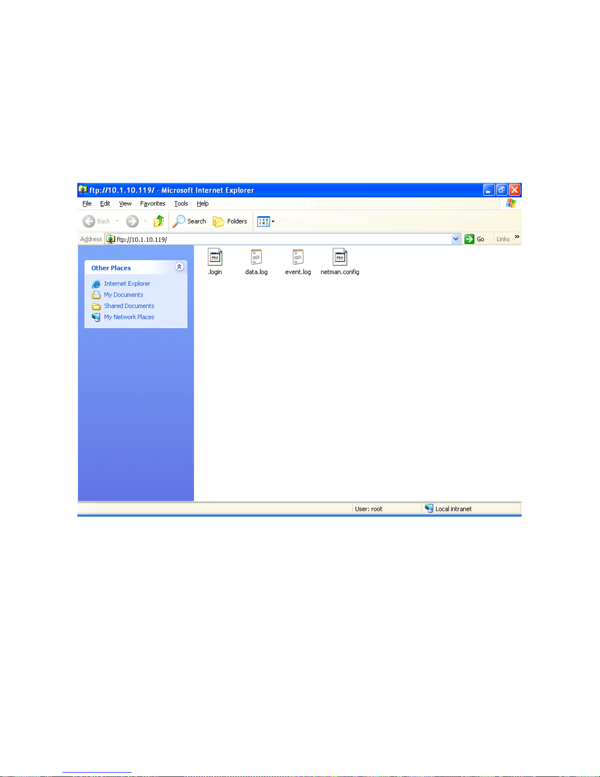
- ENGLISH -
- 90 -
Configuration of several devices
If several devices requiring similar configuration parameters are to be installed, it may be useful to
save the basic configuration to file and then load it on all the devices to be installed. After
completing device configuration, save it by selecting the option “Save to file” from the Save and
load menu (a “netman.config” file will be created). The file can be downloaded from the device and
loaded on another via FTP (see paragraph “FTP”). Once the file has been loaded, select the option
“Load from file” from the Save and load menu and, if necessary, change the configuration for the
new device.
Example of FTP connection for multiple installations
Page 91
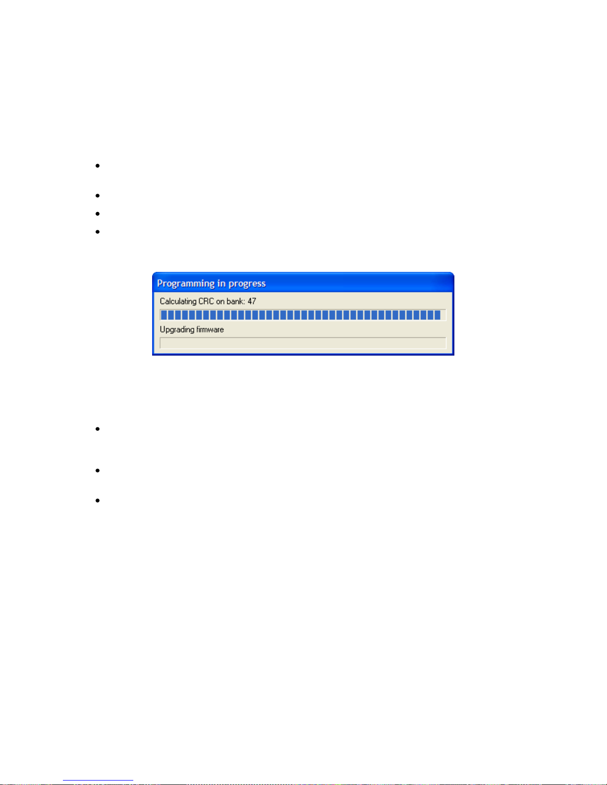
- ENGLISH -
- 91 -
FIRMWARE UPDATE
The NetMan plus firmware can be updated via serial line or via network (Netboot).
WARNING: updating the firmware resets the current password (default configuration: “password”),
loses the clock‟s settings and deletes the event.log and data.log files.
Update via serial line
Connect the “Serial” port of NetMan plus to the serial port of the PC by means of the null-
modem cable provided;
Execute the NetManplus.exe program;
Select the folder containing the update files;
When prompted, press the NetMan plus RESET button and click on the “OK” key. Wait for
the end of the operation.
Firmware update via serial line
Update via network (Netboot)
Configure and start the DHCP/BOOTP server. The DHCP/BOOTP configuration must
include the TFTP server address at the item “next server IP” or “option 150”. On Windows
Server for example, it is “TFTP server name” on “code 66”.
Start the TFTP server; the update file must be present on this server. The TFTP server
must have the address configured in the previous step.
Start the update in one of the following ways:
1. by closing the jumper JP14. NetMan plus automatically starts Netboot at each device
start-up;
2. by sending a network command via Telnet or via UDP as described below. The service
relating to the command used must be active;
Telnet: connect with user “root” and own password, enter the Save and load menu
and select “Netboot”;
UDP: execute the “upgrade <ip address> -n” command (where <ip address> is the
address of NetMan plus). A group of addresses can be set for the simultaneous
update of several NetMan plus; for example, by setting an IP address
10.1.255.255, the command is sent to all the devices within the address range
10.1.*.*.
3. by connecting to the configuration serial port and choosing the “Netboot” option.
Page 92
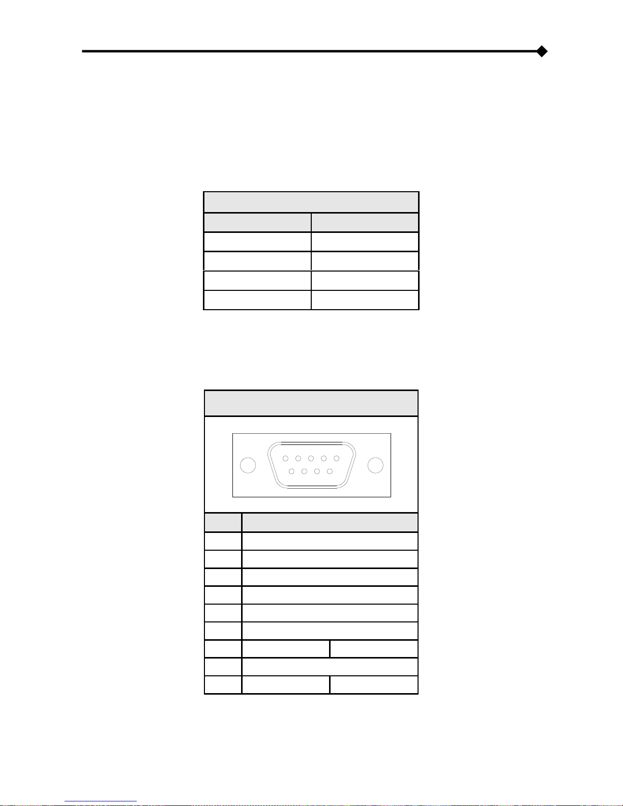
- ENGLISH -
- 92 -
TECHNICAL DATA
SPECIFICATIONS FOR THE CABLING OF THE NETWORK CABLE
To connect the device to the Ethernet (10Base-T) or Fast Ethernet (100Base-T) network, a UTP
(Unshielded Twisted Pair) or STP (Shielded Twisted Pair) cable with RJ45 connectors is required.
The cable must conform to the standard IEEE 802.3u 100Base-T with 2 pairs of UTP cables of
category 5 or higher. The cable between the adaptor and the hub must not be more than 100m and
not less than 2.5m.
NETWORK CABLE CONNECTIONS
Signal
Pin # to Pin #
TX+
1 1
TX-
2 2
RX+
3 3
RX-
6 6
NOTE: pins 1 and 2 must be connected to one twisted pair, pins 3 and 6 to another.
SIGNALS ON THE “SERIAL” CONNECTOR
SERIAL
1 2 3 4
5
6
7
8 9
PIN #
SIGNAL
1
n.c.
2
RXD
3
TXD
4
DTR
5
GND
6
n.c.
7
RTS
(1)
+5V
(2)
8 n.c.
9
n.c.
(1)
Sensor BUS
(2)
n.c. = not connected
(1)
Default jumper settings
(2)
Environmental sensor enabled settings
Page 93

- ENGLISH -
- 93 -
BACKUP BATTERY
The device uses a backup battery for the correct clock working and for maintenance of the
historical data in case of power loss.
In case of long period of inactivity disconnect the battery. It‟s recommended to replace the battery
every three years.
If you have to change the battery ensure that the positive side (+) is facing upwards.
Battery type: CR1620 3V Lithium
TECHNICAL SPECIFICATIONS
NetMan plus
POWER SUPPLY
Input voltage
[Vdc]
12
Maximum inputcurrent
[mA]
200
ENVIRONMENTAL
CONDITIONS
Operating temperature
[°C]
0 ÷ +40
Storage temperature
[°C]
-5 ÷ +50
Operating relative humidity
[%]
80 (max)
Storage relative humidity
[%]
90 (max)
Page 94

0MNUSAPNPF
 Loading...