

Page 1
Quick Installation Guide
AIRNET 54Mb 802.11b/g Indoor
High Power Access Point
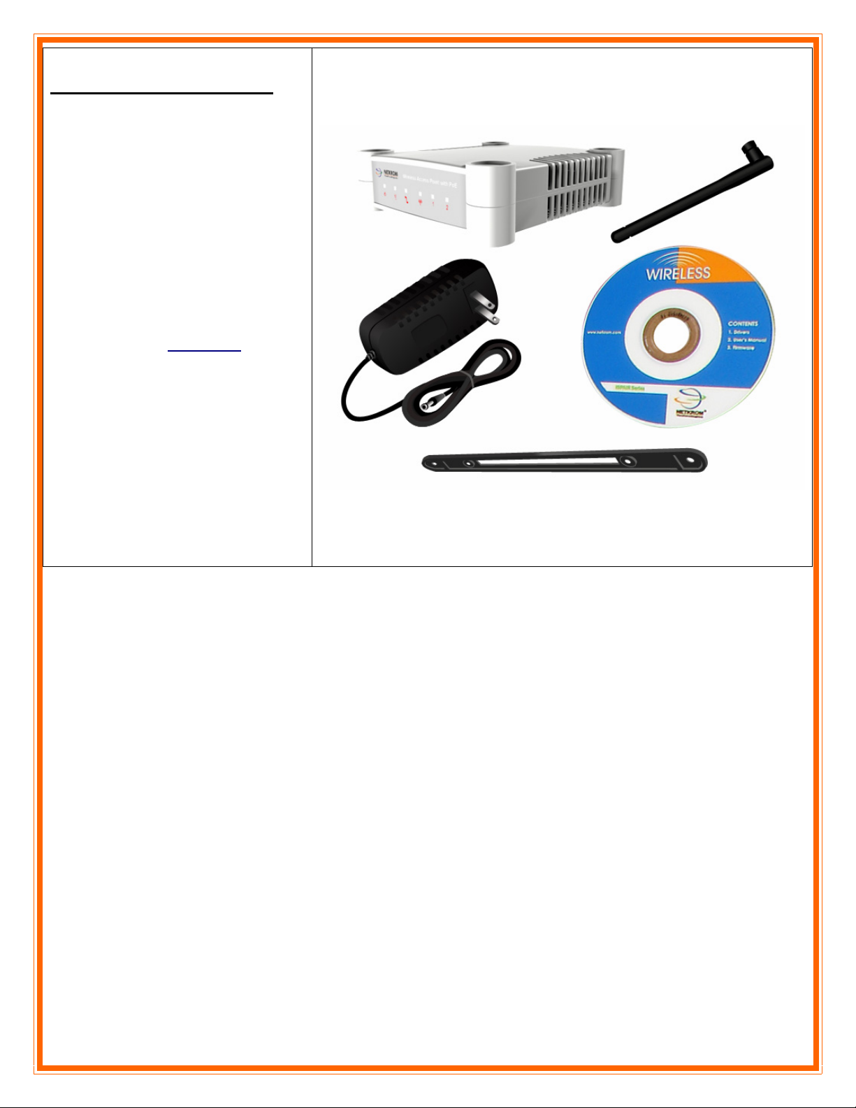
Package Contents:
Airnet Indoor High Power Access Point
Mounting bracket
Power Supply (24VDC)
Detachable antenna
CD-ROM
Page 2

H
1.
Warnings
NETKROM shall not be liable for incidental or consequential damages resulting from the furnishing,
Do not locate the antenna near overhead power lines or other electric light or power circuits, or where it
Only trained and qualified personnel should be allowed to install, replace, or service this equipment.
To meet regulatory restrictions, the radio and the external antenna must be professionally installed. The
The AIRNET Indoor High Power Access Point can be damaged by incorrect power application. Read
H
performance, or use of this manual.
can come into contact with such circuits. When installing the antenna, take extreme care not to come
into contact with such circuits, as they may cause serious injury or death.
network administrator or other IT professional responsible for installing and configuring the unit must
be a suitable professional installer. Following installation, access to the unit should be password
protected by the network administrator to maintain regulatory compliance.
and carefully follow the installation instructions before connecting the system to its power source.
arr
a
d
d
w
w
arr
a
e II
e
nsstt
n
allll
a
attii
a
o
o
n
n
Page 3
Package contents
Take a moment to ensure you
have all of the following parts
in your Indoor Unit installation
kit before you begin installing
the product. If any parts are
missing, please contact your
local vendor or contact us,
please see the contact
AIRNET Indoor High Power Access Point
information in Section 6
.
Page 4
Setup Requirements
Before starting, please verify that the
following is available:
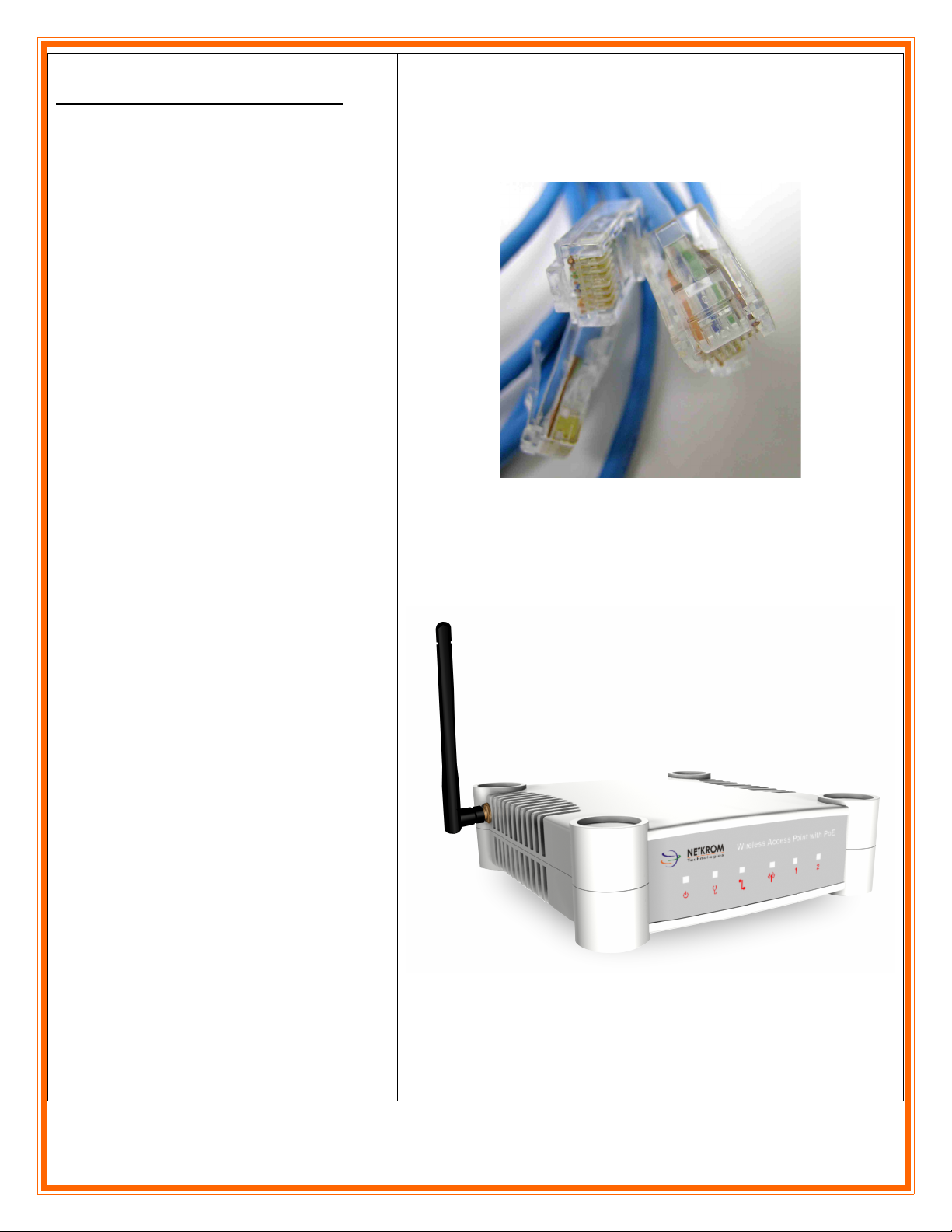
CAT5/5e Ethernet cable (from the
indoor AP to switch or PC)
At least one computer is installed with
a Web browser and a wired or wireless
network interface adapter
TCP/IP protocol is installed and IP
address parameters are properly
configured on all your network’s nodes
Important!
Configure and verify the indoor AP
operations first before you mount the
unit in a remote location.
For choosing the best location for your
Indoor AP choose an elevated location
where obstacles will not obstruct the
antenna signals and which offers
maximum line-of-sight propagation
with the users.
Page 5
AIRNET Indoor High Power Access Point Installation
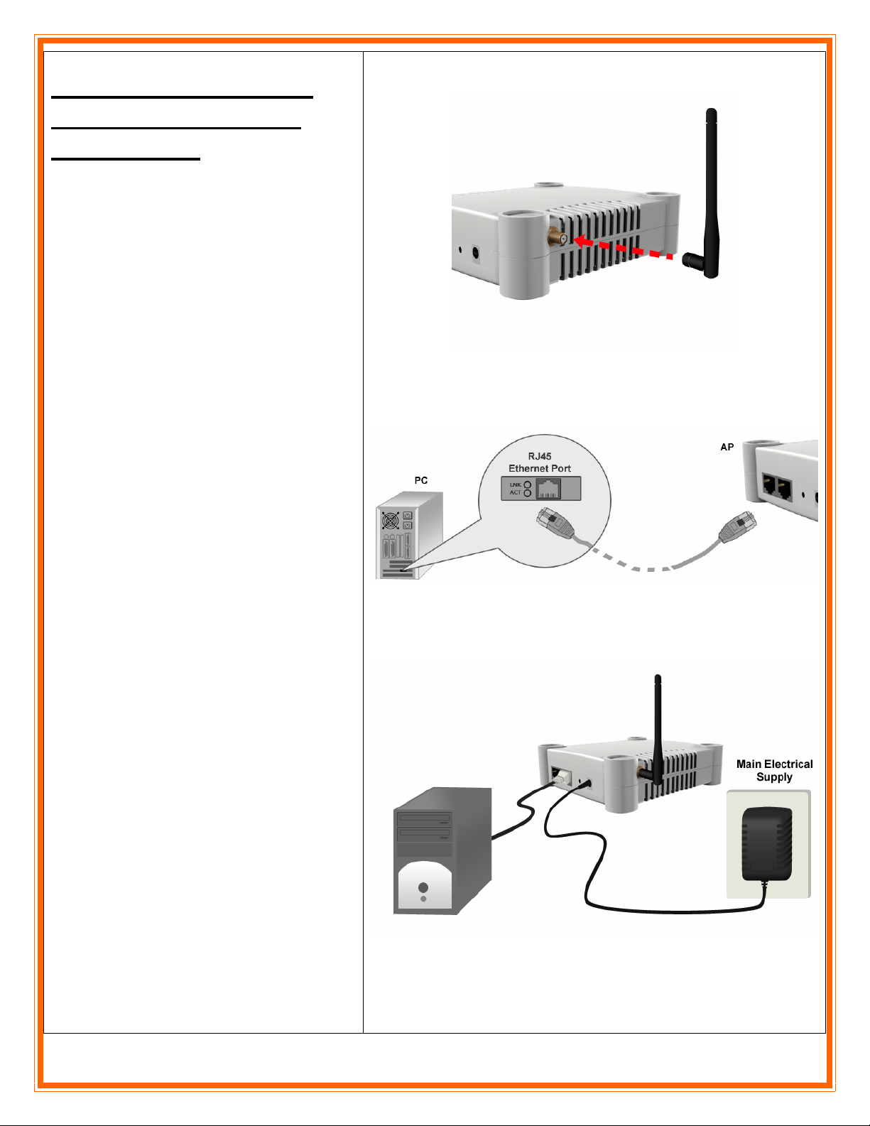
Step 1:
Connect the external antenna to the SMA
connector of the access point.
Step 2:
Insert one end of the Ethernet cable to any
of the Ethernet ports on your access point,
and the other end of the cable to your PC’s
Ethernet network adapter.
Step 3:
Attach the power adapter to the main
electrical supply, and connect the power
plug into the socket of the access point.
Page 6
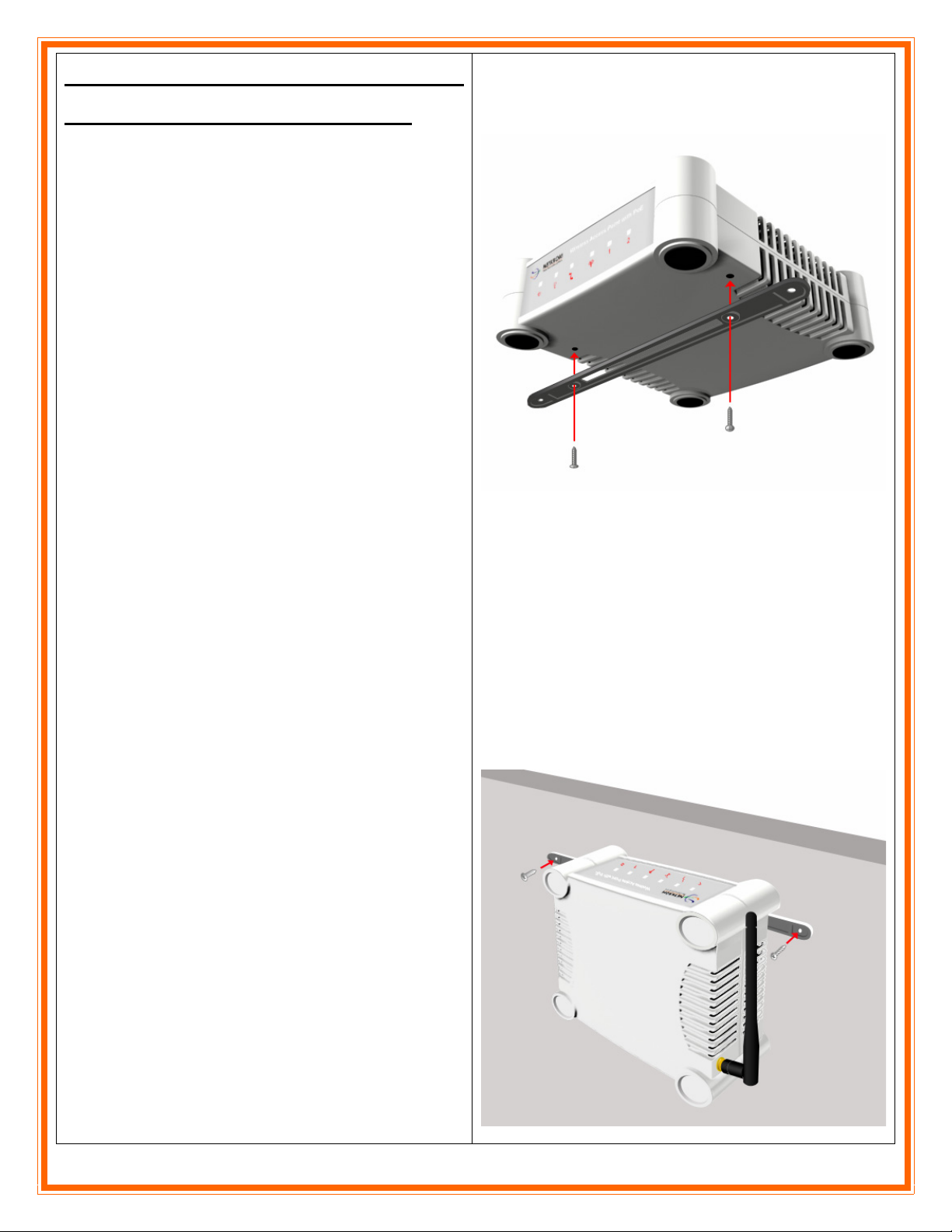
Mounting the Airnet Indoor
High Power Access Point
Step 1:
Screw the mount onto the unit.
Step 2:
Align the unit and mount to the wall.
Using the mount as a guide, make 2 marks and drill 2
holes into the wall.
Step 3:
Screw the mount onto the unit.
Page 7
u
C
o
2.
uConfig is a feature that provides the ability to directly access the AIRNET Indoor High Power Access Point
without the need to know absolutely its IP address. It may be run directly from the product CD or installed on
the user’s PC for later access.
u
C
o
nffii
n
g
g
Uttiilliitt
U
y
y
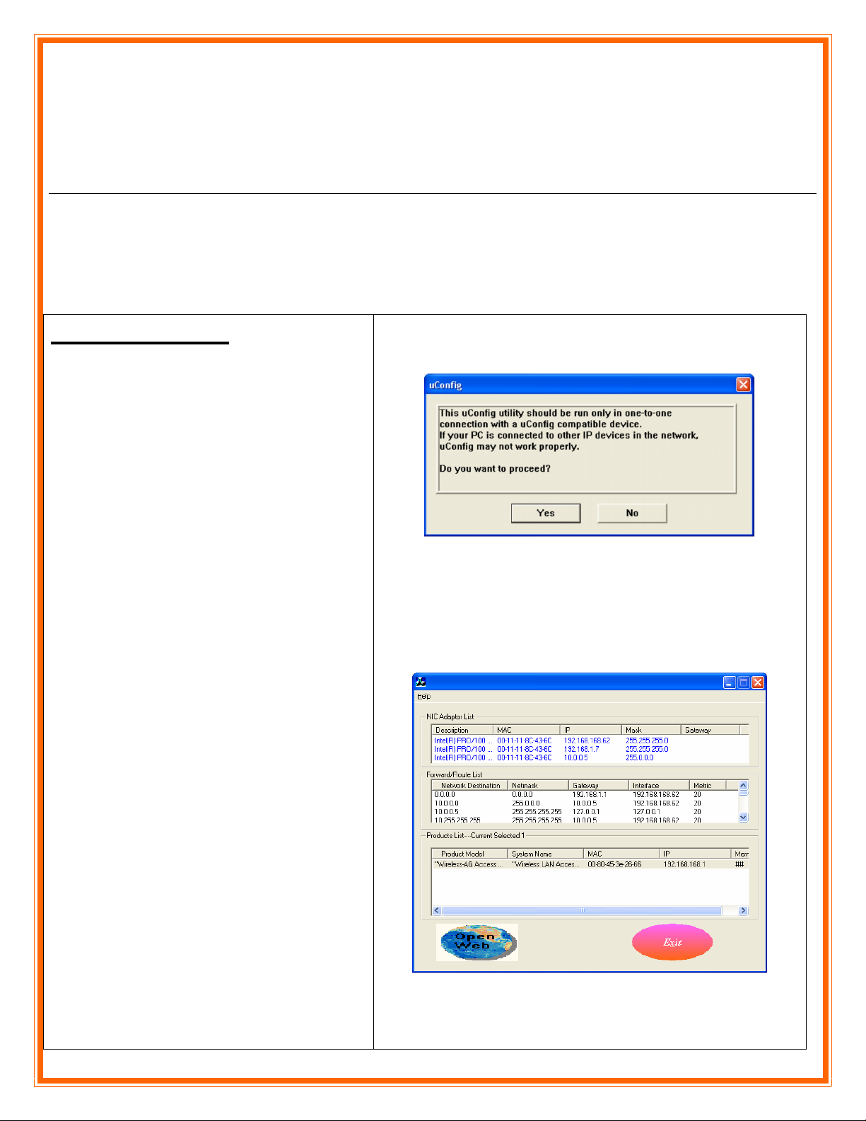
Using uConfig
When you execute the uConfig file you
should see a window as it is shown on the
right side. Click yes to continue
The screen is divided into three sections. The
top section shows the Ethernet adapter that is
accessing the network device and the middle
portion shows the routing table associated
with the Ethernet adapter. In the lower
window, a list of all uConfig compatible
devices on the network is shown.
Highlight the device you desire to configure.
Then click on the “Open web” button
Page 8
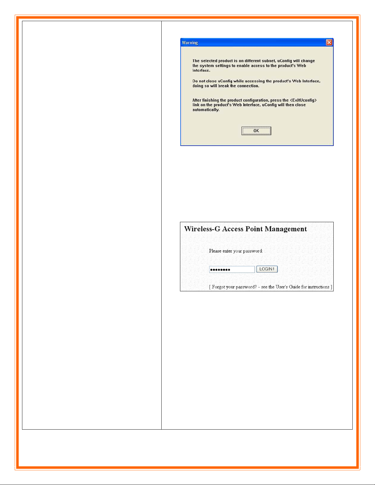
Click the OK button to continue
The default browser will be loaded using the
correct IP address of the AIRNET Indoor
High Power Access Point (regardless of how
the computer’s TCP/IP properties are set),
Default Password: password
Click on LLOOGGIINN!!, and start configuring the
radio.
.
Page 9
P
3.
If you don’t use the uConfig Utility you need to establish Ethernet connection between your PC and the
AIRNET Indoor High Power Access Point, by default the indoor AP has the IP address 192.168.168.1.
Therefore, your PC must be in the same network segment as the AIRNET Indoor High Power Access Point is to
get Ethernet connectivity.
P
C
C
C
C
o
o
nffii
n
g
g
urr
u
attii
a
o
o
n
n
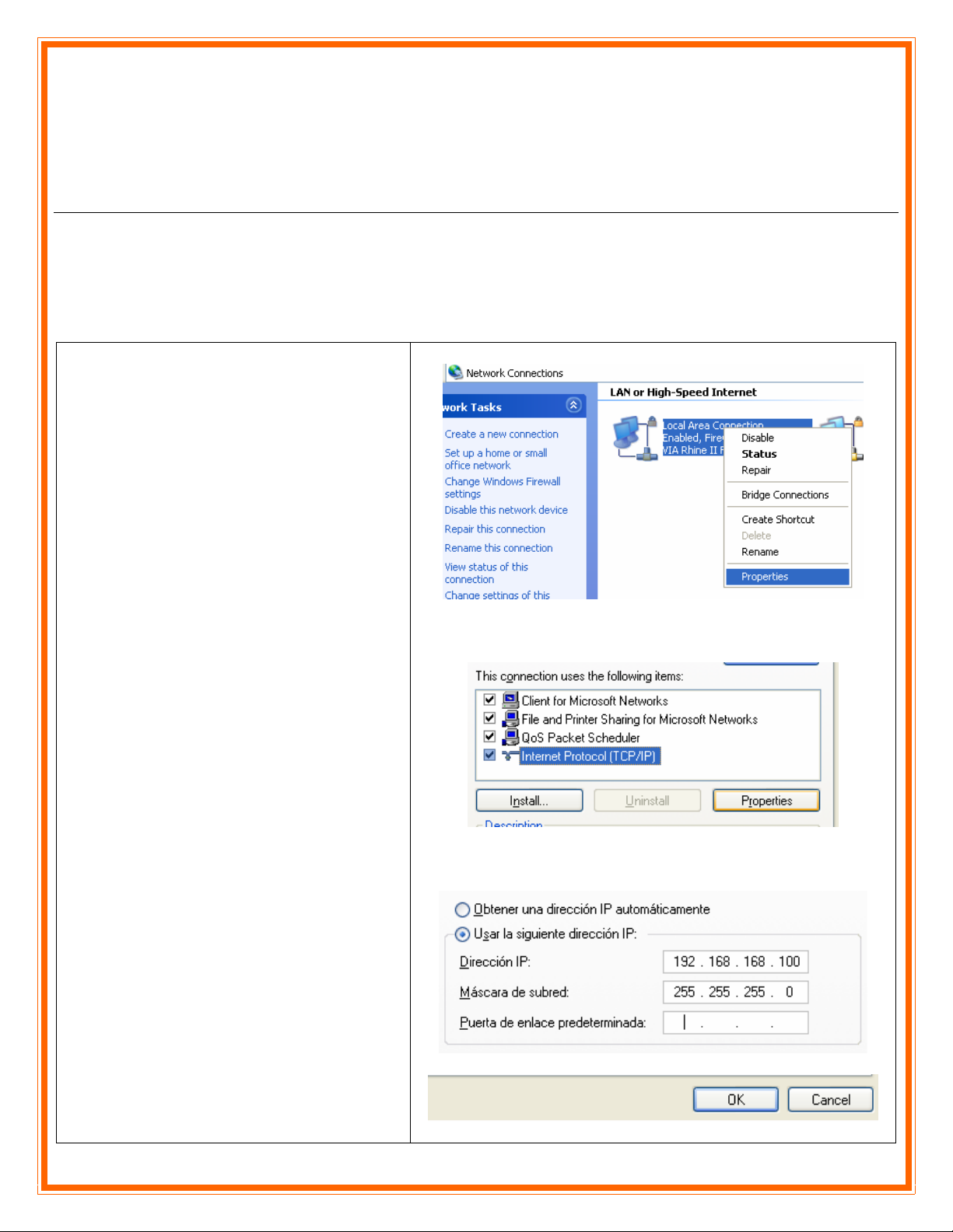
Step 1
Go to Start button, then go to My Network
Places and finally click on Network
Connections.
Right-Click over your network adapter and
select Properties.
Step 2
Select the Internet Protocol Option and then
click in Properties.
Step 3
Now configure the IP Address of your
network adapter with an IP in the same
Network segment as your AIRNET Indoor
High Power Access Point is as it is shown in
the picture, you don’t need to assign any
gateway address.
Press OK and then press the Close button.
Page 10
C
o
4.
Find below typical and basic configurations using the AIRNET Indoor High Power Access Point. For advanced
features please refer to the user manual.
C
o
m
m
m
m
o
o
n
n
C
C
o
o
nffii
n
g
g
urr
u
attii
a
o
nss
o
n
Getting Started
You can start configuring your AIRNET
Indoor High Power Access Point using either
your Web Browser or the uConfig utility.
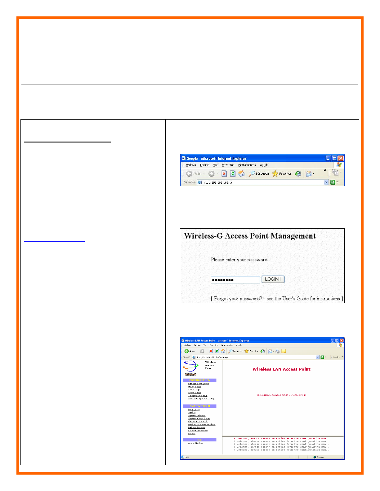
At the Address bar, enter
http://192.168.168.1 and press Enter on your
keyboard.
At the login page, click on the LOGIN!
button to enter the configuration page.
Default Password: password
You will then reach the home page of your
radio’s Web interface.
Page 11
Wireless
Client Mode &
Transparent Client Mode
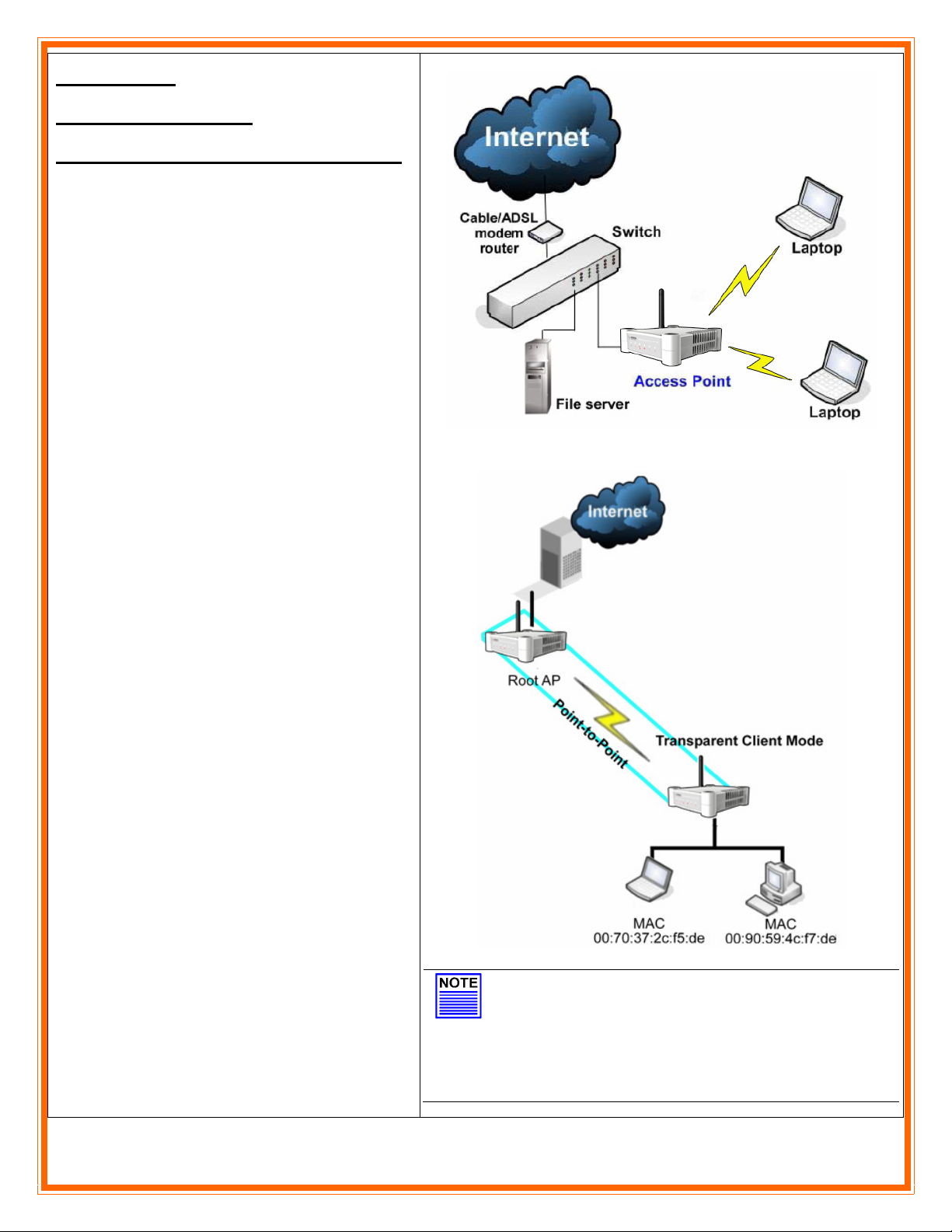
The AIRNET Indoor High Power Access Point
is basically used as an AP in offices, schools to
extend a LAN via wireless. Additionally can
work as a Client and pick up the signal of any
other AP.
You can use the following operational modes
for this purpose:
Transparent Client Mode.
Wireless Client Mode.
NOTE
Client Mode does not provide transparent
bridging.
Transparent Client Mode does provide
transparent bridging.
Page 12
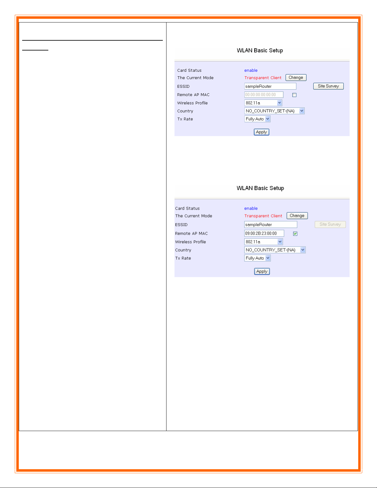
Follow these steps to setup Transparent
Client/s.
Step 1
Select the Remote AP MAC checkbox.
Enter the Remote AP MAC. Check the MAC
address of your Remote AP under About
system >> Wireless MAC.
Ensure that The Current Mode is set to
Transparent Client.
Step 2
Select the Remote AP MAC checkbox.
Enter the Remote AP MAC. Check the MAC
address of your Remote AP under About
system >> Wireless MAC
Note:
When using Remote AP MAC, the ESSID
name must also match the AP’s ESSID name,
especially when Closed System is enabled on
the AP.
Repeat the Transparent Client steps to add
more Clients to the Point-to-MultiPoint
connection.
Page 13
Wireless Point to Point
Setup
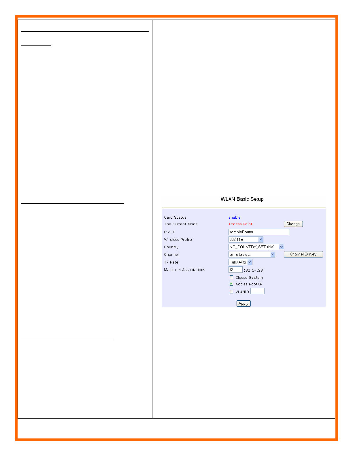
You can implement a Point-to-Point
connection by simply setting one access point
as RootAP in Access Point mode and setting
the other access point in Transparent Client
mode or in Client Mode.
Follow these steps to setup RootAP
Click on WLAN Setup from the
CONFIGURATION menu. You will see the
sub-menus expanded under WLAN Setup.
Click on Basic.
Ensure that The Current Mode is set to
Access Point.
Select Act as RootAP, click on the Apply
button and reboot your device to let your
changes take effect.
Setup Transparent Client Mode
Follow the same procedure explained in the
previous page.
Page 14

5
5
1. - Advanced Routing Configuration: Please go to page 85 of User Manual.
2. – Bandwidth Control:
3. – Remote Management: Please go to page 99 of User Manual.
4. – Advanced Wireless Configuration: Please go to page 114 of User Manual.
5. – Wireless Security Setup: Please go to page 135 of User Manual.
6. – Security Configuration:
7. – Wireless Operation Modes: Please go to page 3 of User Manual.
. Advanced Configuration
.
Please go to page 95 of User Manual.
Please go to page 143 of User Manual.
Page 15

C
o
n
6.
With these basics steps you can enjoy your wireless link without problems, please for more information about
the capabilities and advanced configuration of our product please see the user manual.
C
o
n
grr
g
att
a
ull
u
attii
a
o
nss
o
n
Contact Information
Address:
2134 NW 99th Avenue, Miami FL 33172
Phones:
(+1) 305-418-2232
Fax:
(+1) 305-418-9266
Sales and ordering:
American Customers: [email protected]
Worldwide Customers: [email protected]
Latin American and Spanish Customers: [email protected]
Technical Support:
Worldwide and English Customers: [email protected]
Latin American Customers: [email protected]
 Loading...