

Page 1

Wireless Broadband Router User manual
Wireless Broadband Router
User’s Manual
Page 1 of 54
Page 2

Wireless Broadband Router User manual
This device complies with Part 15 of the FCC Rules. Operation is
subject to the following two conditions:
(1) This device may not cause harmful interference.
(2) This device must accept any interference received, including
interference that may cause undesired operation.
This equipment has been tested and found to comply with the limits for a class B digital device,
pursuant to part 15 of the FCC Rules. These limits are designed to provide reasonable protection
against harmful interference in a residential installation.
This equipment generates, us es an d can radiate radio frequency energy and, if not installed and
used in accordance with the instructions, may cause harmful interference to radio communications.
However, there is no guarantee that interference will not occur in a particular installation. If this
equipment does cause harmful interference to radio or television reception, which can be
determined by turning the equipment off and on, the user is encouraged to try to correct the
interference by one or more of the following measures:
---Reorient or relocate the receiving antenna.
---Increase the separation between the equipment and receiver.
---Connect the equipment into an outlet on a circuit different from that to which the receiver is
connected.
---Consult the dealer or an experienced radio/TV technician for help.
Changes or modifications not expressly approved by the party responsible for complia nce could
void the user's authority to operate the equipment.
FCC RF Radiation Exposure Statement: This equipment complies with FCC RF radiation
exposure limits set forth for an uncontrolled environment. This device and its antenna must not be
co-located or operating in conjunction with any other antenna or transmitter.
Page 2 of 54
Page 3

Wireless Broadband Router User manual
Table of Content s
Chapter 1 Introduction ...................................................................... 5
1.1 Welcome..................................................................................5
1.2 About This Guide.......................................................................5
1.3 Copyright statement .................. ................................................5
Chapter 2 Designing Your Wireless Network .............................. ....... 6
2.1 System Requirements ................................................................6
Chapter 3 Getting to Know the Wireless-G Broadband Router........... 7
3.1 Back Panel................................................................................7
3.2 LED Description.........................................................................8
Chapter 4 hardware connection....................................................... 10
4.1 Connecting the Wireless Broadband Router .................................10
Chapter 5 Configuring Local PC to Access the Wireless Router........ 11
5.1Setting up TCP/IP.....................................................................11
5.1.1 Windows 98/Me...............................................................11
5.1.2 Windows 2000 ................................................................11
5.1.3 Windows XP....................................................................14
5.2 Additional Settings for Wireless Client.........................................17
5.3 Checking PC’s IP and Connection with the Router.........................18
Chapter 6 Web Configuration .......................................................... 20
6.1 Logging In............................................................................ ..20
6.2 Quick Setup Wizard .................................................................21
6.3 Status.................................................................................. ..24
6.3.1 System Status ................................................................24
6.3.2 Statistics........................................................................27
6.4 WAN Setup.............................................................................28
6.4.1 Dynamic IP Address.........................................................28
6.4.2 PPPoE .............................. ..............................................29
6.4.3 Static IP.........................................................................31
6.5 LAN Setup...................................................................... ........32
6.5.1Lan Setup........................................................................32
6.5.2 DHCP Info ......................................................................33
6.6 Wireless Settings............................................................. ........33
6.6.1 Basic Wireless Settings................................ ...... ....... ........33
6.6.2 Advanced Wireless Settings ..............................................34
6.6.3 Wireless Security........................................................... ..35
6.6.4 Wireless MAC Filter............ ..............................................39
6.6.5 Active Clients..................................................................40
6.6.6 WDS Set ........................................................................40
6.7 Routing..................................................................................41
6.8 NAT........................................................................ ...............41
6.8.1 DMZ Host Setup..............................................................41
6.8.2 FTP Private Port...............................................................42
6.8.3 Virtual Server Setup ........................................................42
6.8.4 Port Tiger............ ...........................................................44
6.9 Fire Wall.................................................................................45
Page 3 of 54
Page 4

Wireless Broadband Router User manual
6.9.1 MAC Filtering ................................................... ...............45
6.9.2 Access Control ................................................................46
6.9.3 URL Filtering...................................................................47
6.10 DDNS.............................. .....................................................48
6.11 MISC ...................................................................................48
6.11.1 Login ID & Password Setup .................. ...........................48
6.11.2 Remote Mgmt ................................................. ..............49
6.11.3 WAN Link Status & Setup................................................50
6.11.4 Restore Default / Restart System .....................................50
6.11.4 Firmware Upgrade .........................................................50
Appendix Ⅰ: Troubleshooting ......................................................... 52
Appendix Ⅱ: Features ..................................................................... 54
Page 4 of 54
Page 5

Wireless Broadband Router User manual
Chapter 1 Introduction
1.1 Welcome
Congratulations on purchasing this Wireless Broadband Router. This Wireless
Broadband Router is a cost-effective IP Sharing Router that enables multiple
users to share the Internet through an ADSL or cable modem. Simply configure
your Internet connection settings in the Wireless Broadband Router and plug
your PC to the LAN port and you're ready to share files and access the Internet.
As your network grows, you can connect another hub or switch to the router’s
LAN ports, allowing you to easily expand your network. The Wireless
Broadband Router is embedded with an IEEE 802.11g/b access point that
allows you to build up a wireless LAN. With the support of new emerged
802.11g standard, the access point provides data transfer of up to 54Mbps, up
to 5 times faster than 802.11b, it is backwards compatible with existing
802.11b infrastructure while migrating to the new screaming fast 802.11g.The
Wireless Broadband Router provides a total solution for the Small and
Medium-sized Business (SMB) and the Small Office/Home Office (SOHO)
markets, giving you an instant network today, and the
flexibility to handle tomorrow's expansion and speed.
1.2 About This Guide
This User Manual contains information on how to install and configure your
Wireless Broadband Router to get your network started accessing the Internet.
It will guide you through the correct configuration steps to get your device up
and running.
Note and Caution in this manual are highlighted with graphics as below to
indicate important information.
Contains related information corresponds to a topic.
Necessary steps, actions, or messages that should not be ignored.
1.3 Copyright statement
No part of this publication may be reproduced, stored in a retrieval system, or
Page 5 of 54
Page 6
Wireless Broadband Router User manual
transmitted in any form or by any means, whether electronic, mechanical,
photocopying, recording, or otherwise without the prior writing of the
publisher.
Chapter 2 Designing Your Wireless Network
2.1 System Requirements
z Cable/ADSL modem and an Internet access account for Internet connection
z One computer with 10/100Base-T Ethernet card and TCP/IP protocol
installed for initial s e tup
z Internet Explorer 5.0 or higher for Web configuration
z 802.11g or 802.11b compliant wireless adapters (for wireless connection)
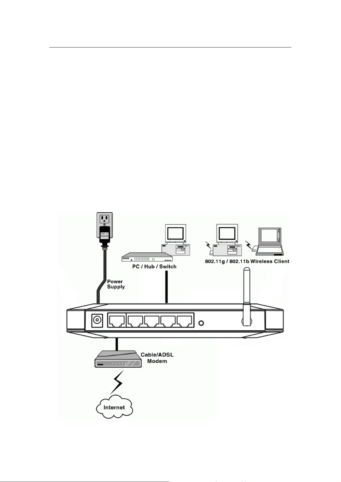
Figure 1 below shows a typical setup for a Local Area Network (LAN).
Page 6 of 54
Page 7

Wireless Broadband Router User manual
Figure 1 Local Area Network
Chapter 3 Getting to Know the Wireless-G
Broadband Router
The following sections describe the physical characteristics of your router.
3.1 Back Panel
The following illustration shows the Wireless Broadband Router back panel:
Power: The receptacle where you plug in the power adapter.
LAN Ports 1-4: These four ports connect the router to your LAN or home
network using Ethernet cables. This enables communication among clients,
such as PCs, on the network. The LAN ports support either 10-BASE-T or
100-BASE-T transmission speeds as well as straight-through and crossover
Ethernet cables. Any of these four ports can also serve as an uplink port to
other network devices, such as another router or switch, which allows you to
1 23 4 5
Figure 2 back panel
Page 7 of 54
Page 8
Wireless Broadband Router User manual
extend your network.
WAN: Connect your modem to your router using this port with your supplied
Ethernet cable. This is the only port you can use for this procedure. This enables
your router to access the Internet. The port supports 10/100 Mbps as well as
straight-through and crossover Ethernet cables.
Reset button: Resets your router or resets the router to the default login
settings.
Antenna: The antenna used for wireless connections. You are able to rotate
the antenna to gain the best signal reception.
If the router experiences trouble connecting to the Internet, briefly press
and release the Reset button to reset the router. To reset the router to the
factory defaults, press and hold the Reset button for more than five seconds.
This clears the router’s user settings, including User ID, Password, IP Address,
and Subnet mask. (Warning: your original configurations will be replaced with
the factory default settings)
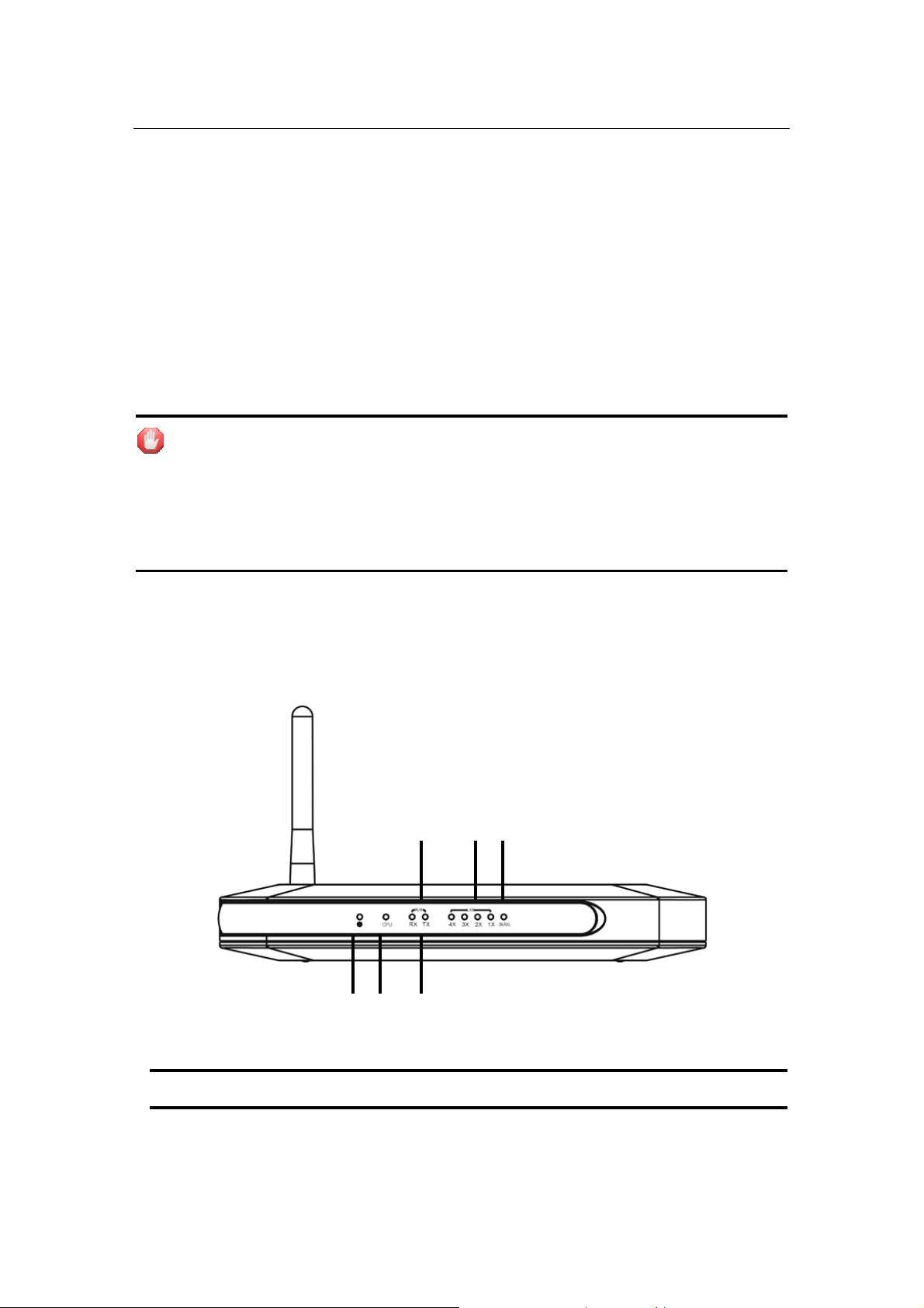
3.2 LED Description
The following illustration shows the Wireless Broadband Router front panel:
4 5 6
1 2 3
Figure 3 front panel
Number LED Light Status Description
Page 8 of 54
Page 9

Wireless Broadband Router User manual
1 PWR ON This indicator lights green when the
Wireless Router is receiving power;
otherwise, it is off.
2 CPU ON The LED will be dark for a few seconds
when the system is started. After that,
the LED will stays green to show the
Wireless Router is working normally. If
the LED stays blink/dark that means the
system failed, you need to contact your
agent or try to reboot the system.
3 WLAN RX Flashing Wireless LAN has Activity (ACT) data
being sent.
4 WLAN TX Flashing Wireless LAN has Activity (ACT) data
being Received
5 WAN ON WAN is connected
Off No WAN connection
Flashing WAN port has Activity (ACT), data being
sent
6 LAN(1-4) ON WAN is connected
Off No WAN connection
Flashing WAN port has Activity (ACT), data being
sent
Page 9 of 54
Page 10

Wireless Broadband Router User manual
Chapter 4 hardware connection
Begin by finding a good place to set up your wireless broadband. Some things
to consider:
z Keep the access point as central in your work area as possible. Signal
strength and speed fall off with distance.
z Higher is often better. For instance, set it up on the top shelf of a bookcase
rather than the bottom one, if possible.
4.1 Connecting the Wireless Broadband Router
Prior to connecting the hardware, make sure to power off your Ethernet device,
Cable/ADSL modem and Wireless Broadband Router. Then follow the steps
below to connect the related devices.
Step 1: Connecting your computer to the LAN port.
Attach one end of the Ethernet cable with RJ-45 connector to your hub, switch
or a computer’s Ethernet port, and the other end to one of the LAN ports of your
Wireless Broadband Router.
Step 2: Connecting Cable/ADSL Modem to the WAN port.
Connect the Ethernet cable attaching to your Cable/ADSL modem to the WAN
port of your Wireless Broadband Router.
Step 3: Connecting the power adapter.
Connect the single DC output connector of the power adapter to the power jack
on the side of the Wireless Broadband Router. Then plug the Power Adapter into
an AC outlet,
Step 4: Power on the following devices in this order: Cable/ADSL
modem, Router, and PCs.
ٛ
Page 10 of 54
Page 11

Wireless Broadband Router User manual
Chapter 5 Configuring Local PC to Access the
Wireless Router
You can manage the Wireless Broadband Router through the Web
browser-based configuration utility. To configure the device via Web browser,
at least one properly configured computer must be connected to the device via
Ethernet or wireless network. The Wireless Broadband Router is configured
with the default IP address of 192.168.10.1 and subnet mask of 255.255.255.0
and its DHCP server is enabled by default. Before setting up the Router, make
sure your PCs are configured to obtain an IP (or TCP/IP) address automatically
from the Router by the steps below.
5.1 Setting up TCP/IP
5.1.1 Windows 98/Me
Step 1: Go to Start Æ Settings Æ Control Panel.
Step 2: Find and double-click the Network icon. The Network dialog box
appears.
Step 3: Click the Configuration label and ensure that you have network card.
Step 4: Select TCP/IP. If TCP/IP appears more than once, please select the item
that has an arrow “Æ” pointing to the network card installed on your computer.
DO NOT choose the instance of TCP/IP with the words “Dial Up Adapter” beside
it.
Step 5: Click Properties. The TCP/IP Properties dialog box appears.
Step 6: Ensure the Obtain IP Address Automatically is checked.
Step 7: From the WINS Configuration dialog box, Ensure that Disable WINS
Resolutio n is checked.
Step 8: From the Gateway dialog box, remove all entries from the Installed
gateways by selecting them and clicking Remove.
Step 9: From the DNS Configuration dialog box, remove all entries from the
DNS Server Search Order box by selecting them and clicking R emove. R emov e
all entries from the Domain Suffix Search Order box by selecting them and
clicking Remove. Clic k Disable DNS.
Step 10: Click OK, back to Network Configuration dialog box
Step 11: Click OK, if prompted to restart, click YES.
5.1.2 Windows 2000
Please follow the steps below to setup your computer:
Page 11 of 54
Page 12
Wireless Broadband Router User manual
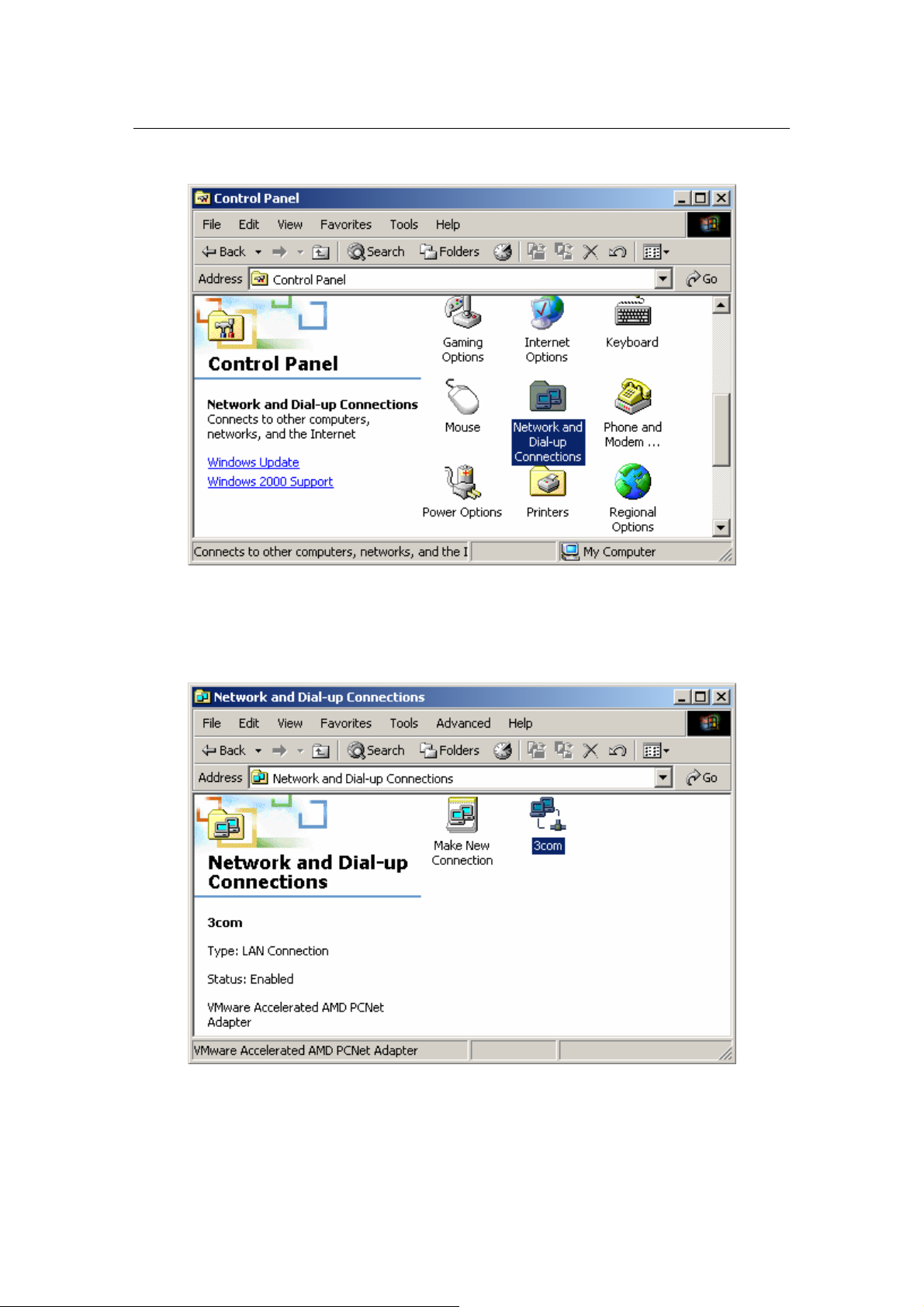
Step 1: Go to Start Æ Settings Æ Control Panel
Figure 4
Step 2: Double click the icon Network and Dial-up Connections
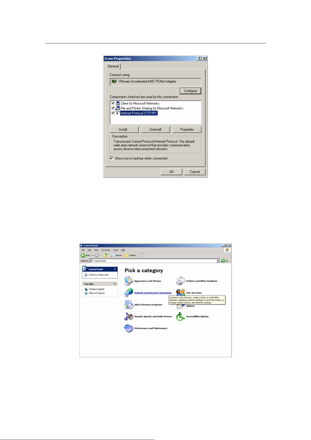
Step 3: Highlight the icon Local Area Connection, right click your
mouse, Click Properties
Figure 5
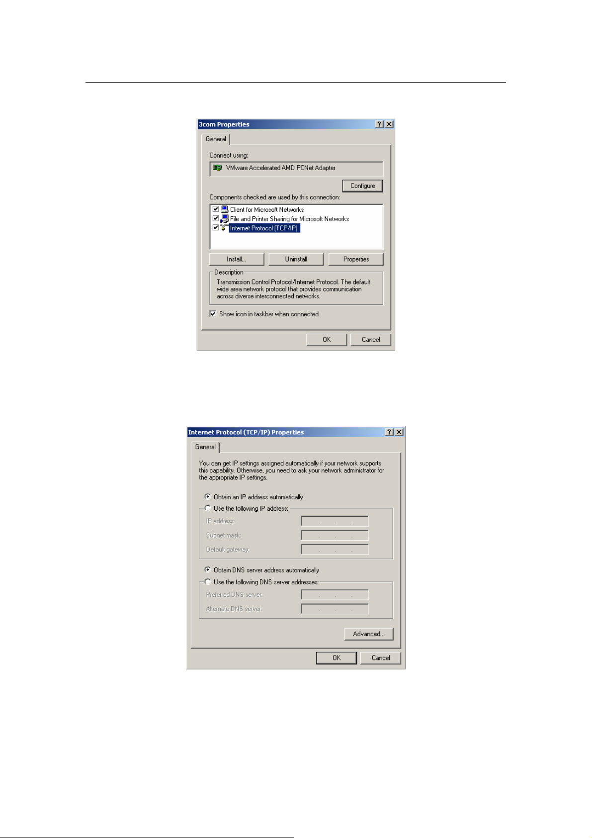
Step 4: Highlight Internet Protocol (TCP/IP), then press Properties
Page 12 of 54
Page 13
Wireless Broadband Router User manual
button
Figure 6
Step 5: Choose Obtain an IP address automatically and Obtain DNS
Server Address automatically, and then press OK to close the Internet
Protocol (TCP/IP) Properties window.
Figure 7
Step 6: Press OK to close the Local Area Connection Properties window
Page 13 of 54
Page 14
Wireless Broadband Router User manual
Figure 8
5.1.3 Windows XP
Please follow the steps below to setup your computer:
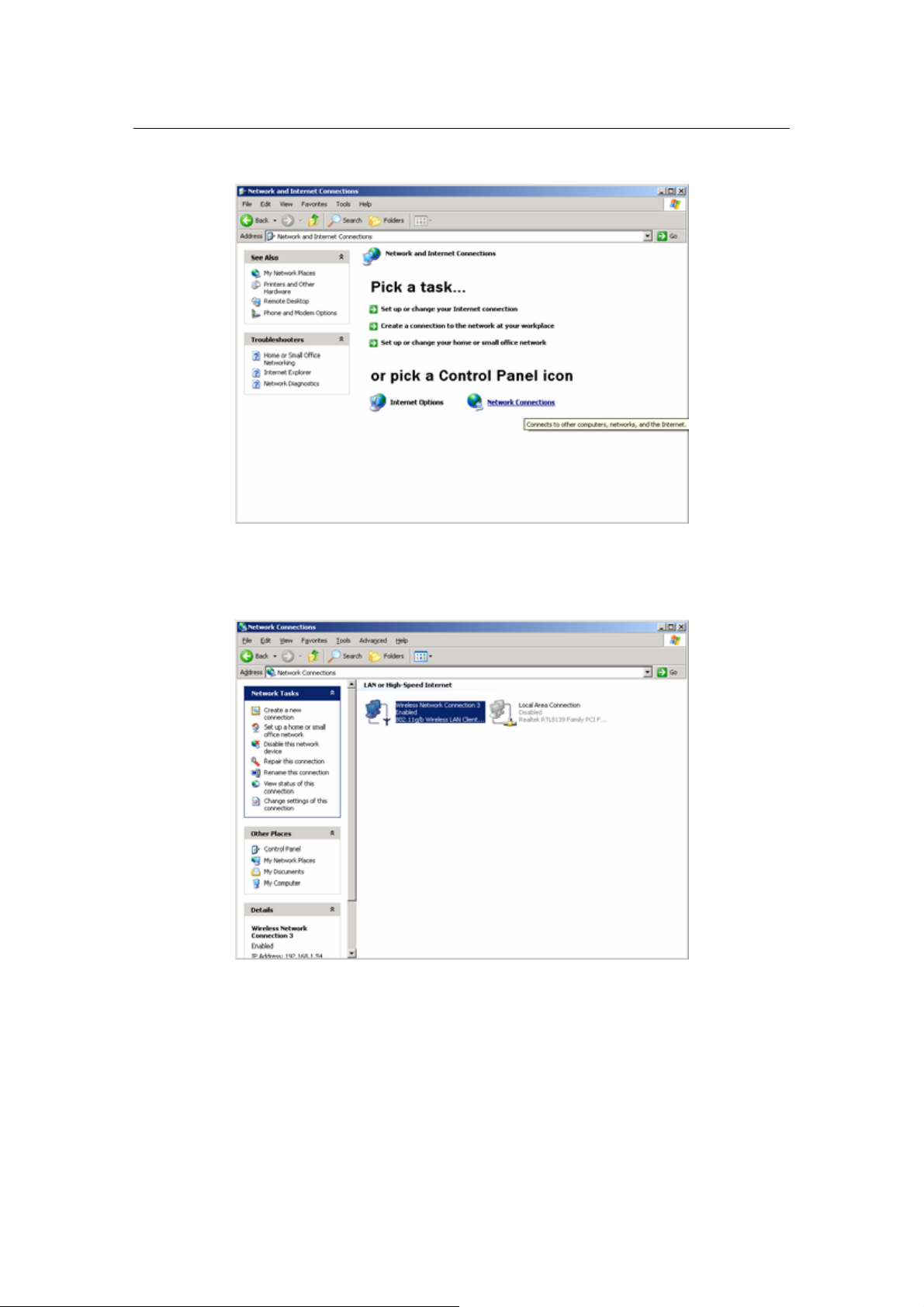
Step 1: Go to Start Æ Settings Æ Control Panel
Step 2: Click Network and Internet Connections
Figure 9
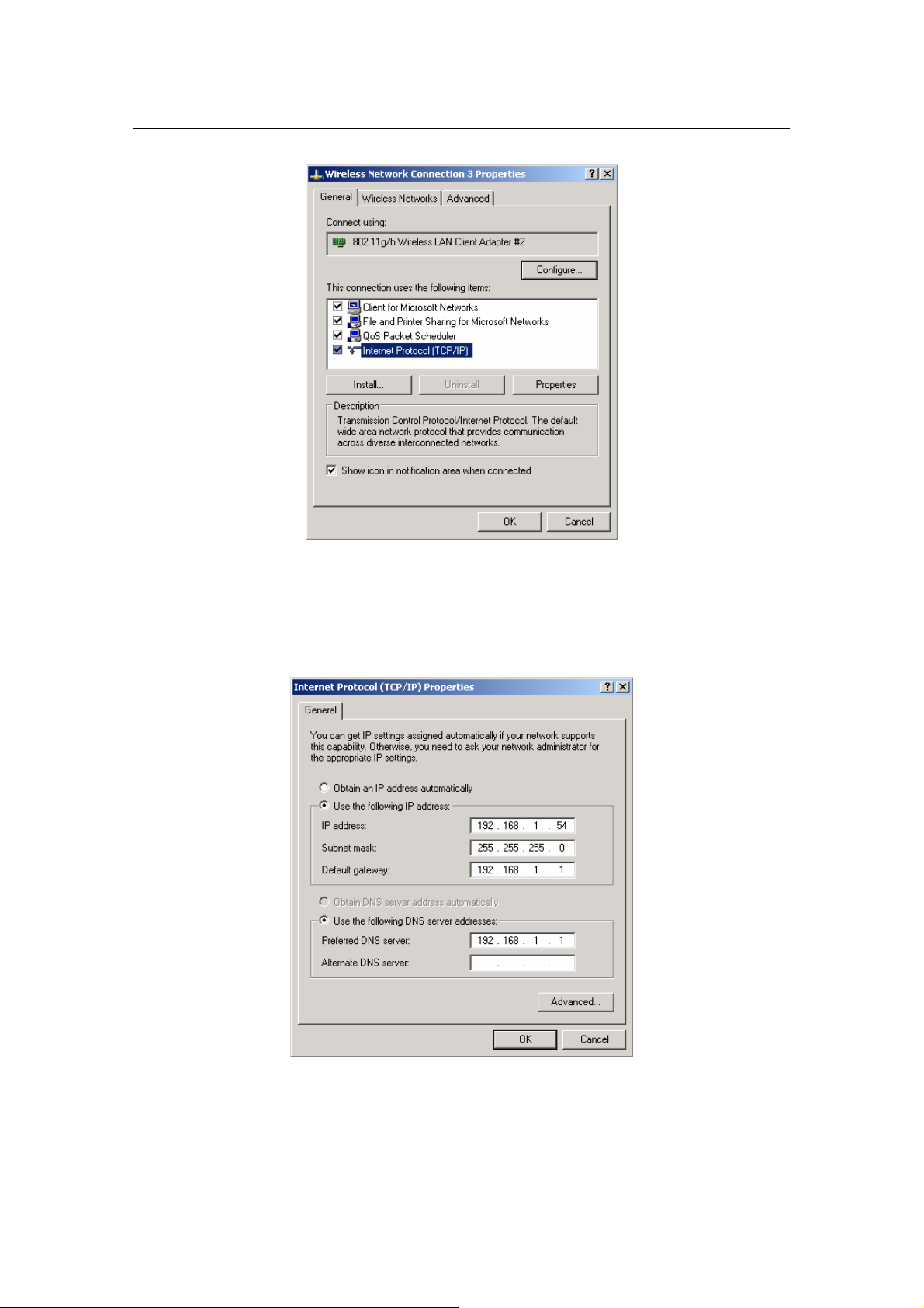
Step 3: Click Network Connections
Page 14 of 54
Page 15
Wireless Broadband Router User manual
Figure 10
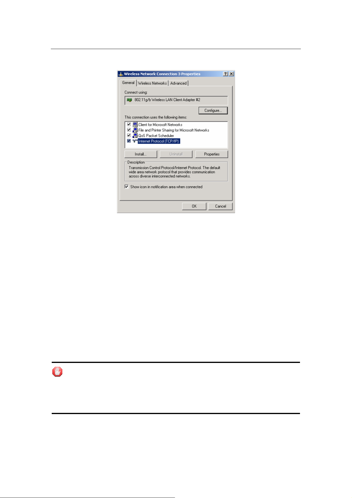
Step 4: Highlight the icon Local Area Connection, right click your
mouse, Click Properties
Figure 11
Step 5: Highlight Internet Protocol (TCP/IP), then press Properties
button
Page 15 of 54
Page 16
Wireless Broadband Router User manual
Figure 12
Step 6: Choose Obtain an IP address automatically and Obtain DNS
Server address automatically, and then press OK to close the Internet
Protocol (TCP/IP) Properties window
Figure 13
Step 7: Press OK to close the Local Area Connection Properties window
Page 16 of 54
Page 17
Wireless Broadband Router User manual
Figure 14
5.2 Additional Settings for Wireless Client
If you chose to access the router via a wireless client, also verify the following:
Step 1: Make sure your PC is equipped with 802.11g or 802.11b wireless
adapter and has appropriate WLAN card driver/utility and TCP/IP installed.
Step 2: Set the wireless adapter to use appropriate TCP/IP settings as
described in previou s section.
Step 3: Launch the wireless adapter’s provided utility and verify that your
wireless client is configured with these settings:
z Operation Mode: Infrastructure
z SSID: default
z Authentication: Disabled
z Encryption: Off
z Radio Ban d: 802.11B/ G
If you only finished the wireless settings and didn’t configure the wireless
adapter’s TCP/IP settings, even your link status indicates a successful
connection with the AP. This connection applies to the “physical” network layer
only. Your wireless adapter cannot communicate with the AP. Make sure to set
the TCP/IP properties as described in this previous section.
Page 17 of 54
Page 18

Wireless Broadband Router User manual
5.3 Checking PC’s IP and Connection with the Router
After configuring the TCP/IP protocol, use the ping command to verify if the
computer can communicate with the Router. To execute the ping command,
open the DOS window and PING the IP address of the Wireless Broadband
Router at the DOS prompt:
z For Windows 98/Me: Start -> Run. Type “command” and click OK.
z For Windows 2000/XP: Start -> Run. Type “cmd” and click OK.
At the DOS prompt, type the following command:
If the Command window returns something similar to the following:
Figure 15
Then the connection between the router and your computer has been
successfully established.
If the computer fails to connect to the router, the Command window will return
the following:
Page 18 of 54
Page 19

Wireless Broadband Router User manual
Figure 16
Verify your computer's network settings are correct and check the cable
connection between the router and the computer.
Page 19 of 54
Page 20

Wireless Broadband Router User manual
Chapter 6 Web Configuration
6.1 Logging In
In order to make the whole network operate successfully, it is necessary to
configure the Wireless Router through your computer has a WEB browser
installed. Please follow up the steps listed below.
Step 1: Start your W eb browser and type http://192.168.10.1 in the Address
field. This address is the default private IP of your router.
Figure 17
If the router’s LAN port has been changed with new IP address, enter the
new IP address instead.
Step 2: After Pressing Enter, you will be able to see the Wireless Broadband
Router’s web-based configuration utility. From now on the Wireless Broadband
Router acts as a Web server sending HTML pages/forms at your request. You
can click the menu options at the left to start the configuration task.
Don’t f orget to change the Password in configuration’s Authentication to
ensure the security . When first configuring your router, it is recommended that
you have an Ethernet cable connected to the router. Performing the INITIAL
configuration using a wireless connection is not secure and i s not recommended.
After you have finished the initial configuration of the router, your connection
will be secure and you can safely use either a wired or wireless connection.
In the home page of the Wireless Router, the left navigation bar shows the main
Page 20 of 54
Page 21
Wireless Broadband Router User manual
options to configure the system. In the right navigation screen is the summary
of system status for viewing the configurations. You can usually get context
sensitive help by clicking on the Help link at the top right of the page.
Figure 18
To apply any settings you’ve altered on any page, click the Save button.
Otherwise you change settings would be lost after the Router reboot.
6.2 Quick Setup Wizard
The Quick Setup section is designed to get you using the broadband router as
quickly as possible. In the Quick Setup you are required to fill in only the
Page 21 of 54
Page 22

Wireless Broadband Router User manual
information necessary to access the Internet.
Step 1: Click on the Wizard in the HOME page, you should see the screen below
then click on “Start”.
Figure 19
Step 2: Select your Internet connection type and then input the config urations
needed to connect to your Internet Service Provider (ISP)
Figure 20
For Dynamic IP Address
z Choose DHCP if your ISP will automatically give you an IP address. And then
click on “Next”.
For PPPoE
z Select PPPoE if your ISP requires the PPPoE protocol to connect you to the
Page 22 of 54
Page 23

Wireless Broadband Router User manual
Internet. Your ISP should provide all the information required in this
section.
z Enter the User Name and Password provided by your ISP for the PPPoE
connection then click on “Next”.
Figure 21
For Static IP
z Select Static IP if your ISP has given you a specific IP address for you to use.
Your ISP should provide all the information required in this section.
z Fill the blank input box with the values which a r e s upplied from your ISP
And then click on “Next”.
Figure 22
z Click “Apply” to save these settings with the Router. The System will apply
Page 23 of 54
Page 24

Wireless Broadband Router User manual
the new settings and start rebooting right away.
Figure 23
z After reboot, the Wireless Router will enable these settings with the Router.
6.3 Status
6.3.1 System Status
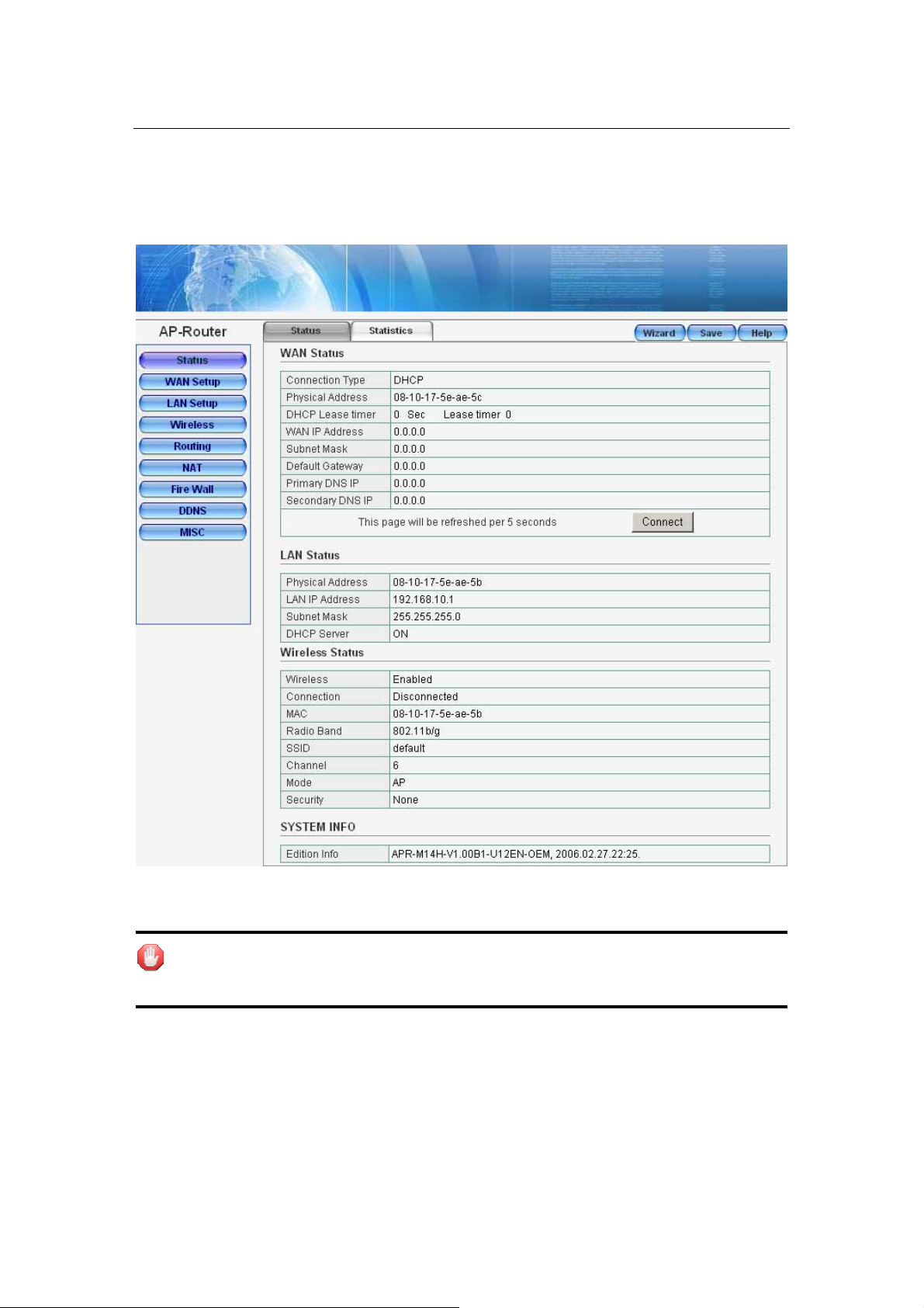
This page shows most of the basic configuration parameters of the R outer. It is
the first page shown after login.
Page 24 of 54
Page 25

Wireless Broadband Router User manual
Figure 24
z WAN Status: This section shows the WAN interface parameters of the
wireless router. This includes information such as: Connection type (DHCP,
PPPoE or Static IP), The MAC address of LAN interface, IP/Subnet Mask,
Default Gateway, Primary DNS, Backup DNS.
PPPoE: In PPPoE mode, if you want to start a connection, click on the
“Connect” button to open a PPPoE session.
Page 25 of 54
Page 26

Wireless Broadband Router User manual
Figure 25
To terminate the connection, click on the “Disconnect” button.
Figure 26
DHCP: In DHCP mode, press "Disconnect" button to release IP address and
press "Connect" button to renew IP address.
Figure 27
Page 26 of 54
Page 27

Wireless Broadband Router User manual
z LAN Status: This section shows the LAN interface parameters of the
wireless router. This includes information such as: The MAC address of LAN
interface, IP/Subnet Mask, DHCP Server (whether the DHCP Server is
Enables or disables, and display address pool).
Figure 28
z Wireless Status: This section shows the WLAN interface parameters of the
wireless router. This includes information such as: Wireless (whether
Wireless interface status is active), Connection (whether have active
wireless stations that are connecting to the AP Router, And display number
of them), The MAC address of WAN interface, Radio Band (The type of
transmission protocol your wireless network uses), SSID, channel number,
security.
Figure 29
z System Information: This section shows the installed version of the
firmware of the Wireless router. And company information.
Figure 30
6.3.2 Statistics
The statistics tab main contains several of the following items for you to
monitor network traffic between interface of types external (WAN) and internal
Page 27 of 54
Page 28

Wireless Broadband Router User manual
(LAN and WLAN). And display System Run Time.
Figure 31
z System Run Time: Display System Run Time.
z Statistics: You can monitor current sent & received packets counters of
wireless and Ethernet networks .To see the latest information, click
“Refresh” button.
6.4 WAN Setup
Use the WAN Setup screen if you have already configured the Quick Setup
Wizard section and you would like to change your Internet connection type. The
WAN Settings screen allows to specify the type of WAN port connect you want
to establish with your ISP. The WAN Setup offer the following selections for the
router’s WAN port, DHCP, PPPoE, Static IP. Select the appropriate connection
mode for your ISP (Internet Service Provider).
6.4.1 Dynamic IP Address
The default setting for the router, DHCP is most commonly used for cable
modem connections. There is no configuration necessary for this setting
because the ISP automatically supplies the information. Choose this type while
Cable mode is used.
Page 28 of 54
Page 29

Wireless Broadband Router User manual
Figure 32
z Physical Address Clone: Y our ISP may require a particular MAC address
in order for you to connect to the Internet. This MAC address is the PC’s
MAC address that your ISP had originally connected your Internet
connection to. Type in this MAC address in this section to replace the WAN
MAC address with the MAC address of that PC (you hav e to be using that PC
for the Clone MAC Address button to work).
z MTU: MTU is the Maximum Transmission Unit. It specifies the largest
packet size permitted for Internet transmission. Enter y our MTU number in
the text-box to set the limitation. The recommended size, entered in the
Size field, is 1496. You should leave this value in the 1200 to 150 0 range.
z DNS: Check "DNS" and enter the IP address to specify DNS server for LAN
DHCP server.
z Click “Apply” to save these settings with the Router. The System will apply
the new settings and start rebooting right away. After reboot, the Wireless
Router will enable these settings with the Router.
6.4.2 PPPoE
Some DSL-based ISPs use PPPoE (Point-to-Point Protocol over Ethernet) to
establish Internet connections. If you are connected to the Internet through a
DSL line, check with your ISP to see if they use PPPoE. If they do , you will hav e
to select PPPoE.
Page 29 of 54
Page 30

Wireless Broadband Router User manual
Figure 33
z PPPoE Account: Enter the User Name provided by your ISP for the PPPoE
connection
z PPPoE Password: Enter the Password provided by your ISP for the PPPoE
connection
z Physical Address Clone: Y our ISP may require a particular MAC address
in order for you to connect to the Internet. This MAC address is the PC’s
MAC address that your ISP had originally connected your Internet
connection to. Type in this MAC address in this section to replace the WAN
MAC address with the MAC address of that PC (you hav e to be using that PC
for the Clone MAC Address button to work).
z MTU: MTU is the Maximum Transmission Unit. It specifies the largest
packet size permitted for Internet transmission. Enter y our MTU number in
the text-box to set the limitation. The default value of MTU is 1492 and use
1300 while the line condition is bad.
z DNS: Check "DNS" and enter the IP address to specify DNS server for LAN
DHCP server.
z Connection Type: Select your PPPoE connection from these options:
Connect to Internet automatically: This feature will keep your Internet
connection always alive. The Router will periodically check your Internet
connection. If you are disconnected, then the Router will automatically
re-establish your connection. To use this option, click the radio button next
to Auto Connect.
Auto disconnect when idle, time out: If enabled, the router will trigger
a PPPoE session for connection to the Internet if any client PC on your
WLAN/LAN sends out a request for Internet access. However, the router
automatically disconnects the PPPoE session after the WAN connection has
been idle for the amount of time you specified in the timeout box. If your
Page 30 of 54
Page 31

Wireless Broadband Router User manual
Internet account is billed based on the amount of time of your Internet
connection, you probably want to enable this option and enter a n idle time
value best suitable for your network. To use this option, click the radio
button next to Connect on demand.
Connect to Internet manually: The router will connect to Internet while
click the “Connect” button on the Web. And the WAN connection will
disconnect. If you click “Disconnect” manually from the Web user i nterface.
The router will not auto-connect to the Internet. T o use thi s option, click the
radio button next to Connect on demand.
z Click “Apply” to save these settings with the Router. The System will apply
the new settings and start rebooting right away. After reboot, the Wireless
Router will enable these settings with the Router.
6.4.3 Static IP
If you are required to use a permanent IP address to connect to the Internet,
select Static IP.
Figure 34
z WAN IP Address: This is the Router’s IP address, when seen from the
Internet. Y our ISP will provide you with the IP Address you need to specify
here.
z Subnet Mask: This is the Router’s Subnet Mask, as seen by users on the
Internet (including your ISP). Your ISP will provide you with the Subnet
Mask.
z Default Gateway: Your ISP will provid e you with the Gateway Address,
which is the ISP server’s IP address.
z Physical Address Clone: Y our ISP may require a particular MAC address
in order for you to connect to the Internet. This MAC address is the PC’s
MAC address that your ISP had originally connected your Internet
Page 31 of 54
Page 32
Wireless Broadband Router User manual
connection to. Type in this MAC address in this section to replace the WAN
MAC address with the MAC address of that PC (you hav e to be using that PC
for the Clone MAC Address button to work).
z MTU: MTU is the Maximum Transmission Unit. It specifies the largest
packet size permitted for Internet transmission. Enter y our MTU number in
the text-box to set the limitation. The recommended size, entered in the
Size field, is 1496. You should leave this value in the 1200 to 150 0 range.
z DNS: Check "DNS" and enter the IP address to specify DNS server for LAN
DHCP server.
z Click “Apply” to save these settings with the Router. The System will apply
the new settings and start rebooting right away. After reboot, the Wireless
Router will enable these settings with the Router.
6.5 LAN Setup
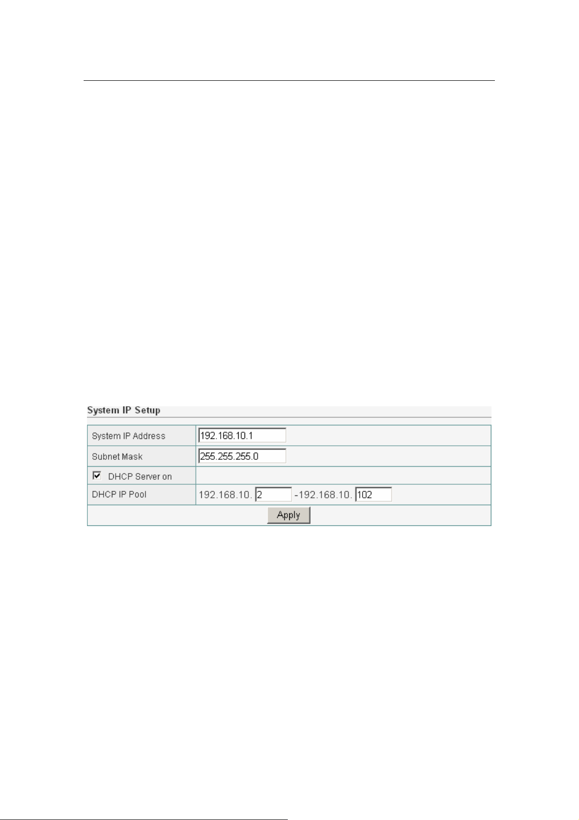
6.5.1 LAN Setup
The Wireless Broadband Router communicates with the wired/wireless clients
through its LAN port. The LAN configuration page allows you to define the
private IP address and DHCP server settings over the LAN interface.
Figure 35
z IP Address/Subnet Mask: Enter the IP address and subnet mask for the
Wireless Broadband Router LAN port. All local wired/wireless devices
communicate with the device through this port. It is also the IP address of
the Web-based Configuration Utility. By default, the IP address and subnet
mask of the LAN port is 192.168.10.1 and 255.255.255.0 respectively.
z DHCP Server: The DHCP server can be ON or OFF in this screen. If you
choose to set this device as a DHCP server, then it will assign IP addresses
to its clients. The DHCP pool range is also changeable.
z Click “Apply” when you have finished the configuration above. And the
wireless router will be automatically restarted if you change the LAN IP
address.
Page 32 of 54
Page 33

Wireless Broadband Router User manual
If you change the private IP address and apply the changes, the PC from
which you configure the router will lose the communication to the router. To
reconnect, you will need to renew the IP address of the PC or change to an IP
address compatible with the new LAN port IP address.
6.5.2 DHCP Info
You can View all the pc which connect to the Wireless Router by DHCP here.
Figure 36
6.6 Wireless Settings
The Wireless Broadband Router implements Access Point capability, which
connects wireless clients to a wired LAN. It allows wireless stations to access
network resources and share the broadband Internet connection.
6.6.1 Basic Wireless Settings
The basic settings for wireless networking are set on this screen.
Figure 37
z Radio Band: The default setting is mixed mode [802.11B/G]. If you do not
Page 33 of 54
Page 34

Wireless Broadband Router User manual
know or have both 11g and 11b devices in your network, then keep the
default in mixed mode. From the drop-down manual, you can select
802.11G if you have only 11G card. If you have only 802.11 B card, then
select 802.11B.
z Radio Mode: The Route has 3 modes: AP, WDS, AP+WDS
z SSID: The SSID is the network name shared among all points in a wireless
network. The SSID must be identical for all devices in the wireless network.
It is case-sensitive and must not exceed 32 characters (use any of the
characters on the keyboard). Make sure this setting is the same for all
points in your wireless network. For added security, you should change the
default SSID (default) to a unique name.
z Channel: Select the channel used for wireless communication. There are
11 overlapping channels. Channels 1, 6 and 11are non-overlapping. The
default is channel 6.
z Click “Apply” when you have finished the configuration above.
z Please setup authentication and Encryption mode to setup Valid and Safe
wireless connection after setting Basic Wireless parameters.
6.6.2 Advanced Wireless Settings
This tab is used to set up the Router’s advanced wireless functions. These
settings should only be adjusted by an expert administrator as incorrect
settings can reduce wireless performance.
Figure 38
z Beacon Interval: This value indicates the frequency interval of the beacon.
A beacon is a packet broadcast by the wireless router to keep the network
synchronized. A beacon includes the wireless LAN service area, a time
stamp, Delivery Traffic Indicator Maps, and the Traffic Indicator Message
(TIM). The default value is 100.
z RTS Threshold: This value should remain at its default setting of 2,347.
Should you encounter inconsistent data flow, only minor modifications are
recommended.
Page 34 of 54
Page 35

Wireless Broadband Router User manual
z DTIM Interval: This value indicates how often the Access Point sends out
a Delivery Traffic Indication Message (DTIM). Lower settings result in more
efficient networking, while preventing your PC from dropping into power
saving sleep mode. Higher settings allow your PC to enter sleep mode, thus
saving power, but interferes with wireless transmissions.
z Transmit Rate: The “Transmit Rate “is the data packets limitation this
wireless router can transmit, The wireless router will use the highest
possible selected transmission rate to transmit the data packets. The
default value is Auto.
z Preamble Type: It defines the length of CRC block in the frames during
the wireless Communication. "Short Preamble" is suitable for heavy traffic
wireless network. "Long Preamble" provides much communication
reliability
6.6.3 Wireless Security
This wireless router provides complete wireless LAN security functions; include
WEP, WPA with pre-shared key and WPA2 with pre-shared key. With these
security functions, you can prevent your wireless LAN from illegal access.
Please make sure your wireless stations use the same security function.
6.6.3.1 None
Transmit data without encryption and authentication. This is the default option.
Figure 39
z Click “Apply” when you have selected the “None”.
If you select none, any data will be transmitted without Encryption and
any station can access the wireless router.
6.6.3.2 WEP
WEP (Wired Equivalent Privacy) is an encryption method used to protect your
Page 35 of 54
Page 36

Wireless Broadband Router User manual
wireless data communications. WEP uses a combination of 64-bit or 128-bit
keys to provide access control to your network and encryption security for
every data transmission.
Figure 40
z Open-System: No authentication is used. But uses WEP encrypt data
packets.
z Share-keys: Authentication is a process in which the AP validates whether
the wireless client is qualified to access the AP’s service. You must enable
WEP function and define your WEP keys. The keys are used both to
authenticate wireless clients and encrypt outgoing data.
z Auto-Select: It can detect Wireless Client authentication information, and
automatically choose Open-System or Share-Keys mode to communicate
with client. When use Auto-Select mode, you must setup WEP keys which
are used by authentication system.
z WEP Length: Selects 64-bit or 128-bit WEP encryption. Be sure that the
key length setting in the AP shall be the same as in wireless cli ents, or the
communication w il l not work.
z WEP Mode: You may select to select ASCII Characters or Hexadecimal
Digits (in the "A-F", "a-f" and "0-9" range) to be the WEP Key.
z Default Key: The Key selected here must match the key selected in the
client. For example, if you select Key 1 here you have to select Key 1 for the
client. The default is 1.
z Key 1~4: Enter one to four WEP keys in either ASCII or Hexadecimal
format. You can use 64 bits or 128 bits as the encryption algorithm.
Enter one to four WEP keys in either ASCII or Hexadecimal format. You can u se
64 bits or 128 bits as the encryption algorithm.
Note that when using Hexadecimal format, only digits 0-9 and letters A-F, a-f
Page 36 of 54
Page 37

Wireless Broadband Router User manual
are allowed. Valid key length for each encryption type is as below:
Key Length HEX Format ASCII Format
64 Bit 10 hexadecimal digits 5 ASCII characters
128 Bit 26 hexadecimal digits 13 ASCII characters
z Click “Apply” at the bottom of the screen to save the above configurations.
6.6.3.3 WPA Personal
Wi-Fi Protected Access (WPA) is an advanced security standard. You can use a
pre-shared key to authenticate wireless stations and encrypt data during
communication. It uses TKIP and AES to change the encryption key frequently.
This can improve security very much.
Figure 41
z TKIP: Temporal Key Integrity Protocol (TKIP) utilizes a stronger encryption
algorithm and includes Message Integrity Code (MIC) to provide protection
against hackers.
z AES: Advanced Encryption System (AES) utilizes a symmetric 128-Bit
block data encryption. It’s the strongest encryption currently available.
z WPA Pass Phrase: The WPA Pass Phrase is used to authenticate and
encrypt data transmitted in the wireless network. The input format is in
character style and key size should be in the range between 8 and 63
characters.
z Clear: If you want to retype again. Just click "Cl ear" and "WPA Pass Phrase"
fields will be cleared.
z Rekey Time (sec): Specifies the timer the WPA key must changes. The
Page 37 of 54
Page 38

Wireless Broadband Router User manual
change is done automatically between the server and the client. The default
value is 86400.
z Click “Apply” at the bottom of the screen to save the above configurations.
6.6.3.4 WPA2 Personal
The WPA2 is a stronger version of WPA. You can use a pre-shared key to
authenticate wireless stations and encrypt data during communication. It uses
AES to change the encryption key frequently. This can imp rove security very
much.
Figure 42
z AES: Advanced Encryption System (AES) utilizes a symme tric 128-Bit
block data encryption. It’s the strongest encryption currently available.
z WPA Pass Phrase: The WPA Pass Phrase is used to authenticate and
encrypt data transmitted in the wireless network. The input format is in
character style and key size should be in the range between 8 and 63
characters.
z Clear: If you want to retype again. Just click "Cl ear" and "WPA Pass Phrase"
fields will be cleared.
z Rekey Time (sec): Specifies the timer the WPA key must changes. The
change is done automatically between the server and the client. The default
value is 86400.
z Click “Apply” at the bottom of the screen to save the above configurations.
6.6.3.5 WPA&WPA2 Personal
Auto-Select WPA/WPA2 can detect Wire less C lient authenticat ion information ,
and automatically choose WPA or WPA2 mode to communicate with client.
Operation is the same as WPA or WPA2.
Page 38 of 54
Page 39

Wireless Broadband Router User manual
Figure 43
z Click “Apply” at the bottom of the screen to save the above configurations.
6.6.4 Wireless MAC Filter
This Wireless router has the capability to control the wireless client access
based on the MAC address of the wireless client. The user has the flexibility to
customize your own control policy based on these options:
Figure 44
z Enable Wireless Access Control: To enable Wireless MAC Filter, click the
check box. The default is “disable”.
z You can choose a default operation for your factual security or management
consideration:
Defined items in MAC list are PERMIT to connect AP, others are DENIED.
Page 39 of 54
Page 40

Wireless Broadband Router User manual
Defined items in MAC list are DENIED to connect AP, others are PERMIT.
Click “Apply” when you have selected,
z MAC: Enter the MAC Address of a station.
z Description: Enter the Comment of station.
z Click "Add”. Then this wireless station will be added into the” Current
Access Control List" below.
z
Figure 45
z If you want to remove some MAC address from the "Current Access Control
List ", select the MAC addresses you want to remove in the list and then
click "Delete ".
6.6.5 Active Clients
You can see the status of all active wireless stations that are connecting to the
wireless router.
Figure 46
z To see the latest information, click Refresh button.
6.6.6 WDS Set
You can set the wireless Bridge MAC here. The bridge uses to connect between
more than 2 routers.
Figure 47
Page 40 of 54
Page 41

Wireless Broadband Router User manual
6.7 Routing
If the Router is connected to more than one network, it may be necessary to set
up a static route between them. A static route is a pre-determined pathway that
network information must travel to reach a specific host or network.
Figure 48
z Type / Target / Mask / Gateway: Fill in these fields required by this
Static Routing function.
z Add: Fill in the all of the setting to be added and then click "Add". Then this
Special Application setting will be added into the "C u rrent Routing Table"
below.
z Current Routing Table: This display shows the valid routing paths in
Broadband Router. User can view the information about current routing
paths
z If you want to remove some route entries from the “Current Routing Table
", select the Route entry you want to remove in the table and then click
"Delete ".
6.8 NAT
Network Address Translation (NAT) allows multiple users at your local site to
access the Internet through a single Public IP Address. NAT provides Firewall
protection from hacker attacks and has the flexibility to allow you to map
Private IP Addresses to Public IP Addresses for key services such as Websites
and FTP.
6.8.1 DMZ Host Setup
If you have a local client P C that cannot run an Internet application (e.g. Games)
properly from behind the NAT firewall, then you can open the client up to
unrestricted two-way Internet access by defining a DMZ Host. The DMZ
function allows you to re-direct all packets going to your W AN port IP address to
Page 41 of 54
Page 42
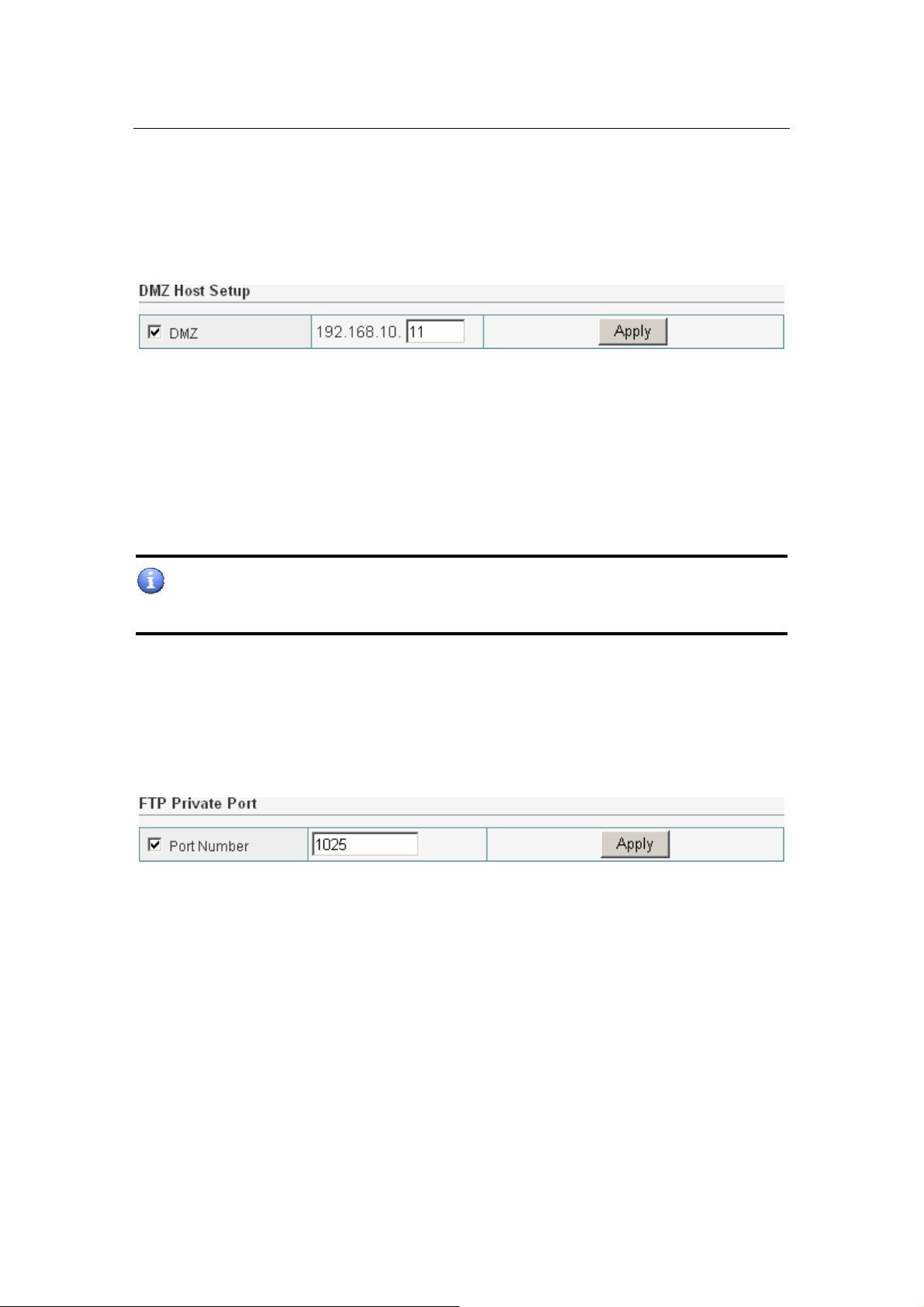
Wireless Broadband Router User manual
a particular IP address in your LAN. The difference between the virtual server
and the DMZ function is that the virtual server re-directs a particular
service/Internet application (e.g. FTP, websites) to a particular LAN
client/server, whereas DMZ re-directs all packets (regardless of services) going
to your WAN IP address to a particular LAN client/server.
Figure 49
z DMZ : Enable/disable DMZ
z DMZ Host: Input the IP address of a particular host in your LAN that will
receive all the packets originally going to the WAN port/Public IP address
above, you need to give your LAN PC clients a fixed/static IP address for
DMZ to work properly.
z Click “Apply” at the bottom of the screen to save the DMZ configurations.
If there is a conflict between the Virtual Server and the DMZ setting, then
Virtual Server function will have priority over the DMZ function.
6.8.2 FTP Private Port
FTP private port enables user to setup FTP server which is not using the
standard port 21.
Figure 50
z Check port number and enter the number and then press the "Apply"
button to setup Private FTP port. The default Value is 1025.
6.8.3 Virtual Server Setup
Use the Virtual Server function when you want different servers/clients in y our
LAN to handle different service/Internet application type (e.g. Email, FTP, Web
server etc.) from the Internet. Computers use numbers called port numbers to
recognize a particular service/Internet application type. The Virtual Server
allows you to re-direct a particular service port number (from the Internet/W AN
Page 42 of 54
Page 43

Wireless Broadband Router User manual
Port) to a particular LAN private IP address and its service port number.
Figure 51
z Rule Name: You can enter whatever you want. It's just a string.
z Internal Server IP: Enter the host IP address to which the packet will be
forwarded. The virtual server can be set easily by setting the internal server
IP address only. You need to give your LAN PC clients a fixed/static IP
address for Virtual Server to work properly.
z Protocol: Chose TCP/UDP type for the packet you want to forward. If the
rule existed in predefined virtual server rule, you can choose the rule.
z External Port: Enter the port number (The value's range is 1 to 65535)
from which the packet will be on WAN.
z Internal Port: Enter the port number to which the packet will be
forwarded on LAN
z Press "Add" button after enter the all fields to add the rule.
z Check to select the rule and press "Delete" to delete the rule.
Figure 52
The diagram below demonstrates one of the ways you can use the Virtual
Server function. Use the Virtual Server when you want the FTP server located in
your private LAN to be accessible to Internet users. The configuration below
means that any request coming form the Internet to access your web server will
be translated to your LAN’s FTP server (192.168.10.6). Note: For the virtual
server to work properly Internet/remote users must know your global IP
address.
Page 43 of 54
Page 44

Wireless Broadband Router User manual
Figure 53
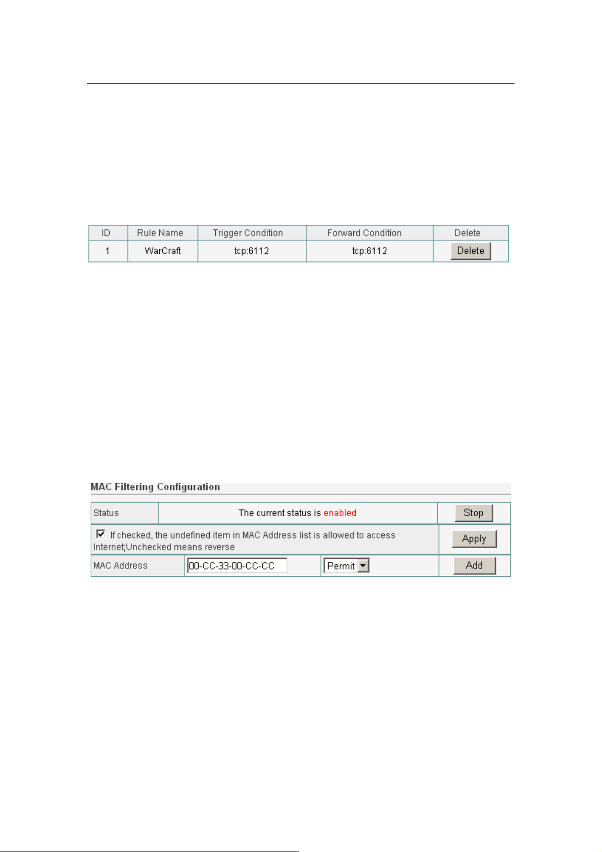
6.8.4 Port Trigger
Port Trigger set the port you want used for some special use.
Figure 54
z Rule Name: You can enter whatever you want. It's just a string.
z Trigger Protocol: Chose TCP/UDP type for the packet you want to trigger.
If the rule existed in predefined virtual server rule, you can choose the rule.
z Trigger Port: Enter the port number (The value's range is 1 to 65535)
Page 44 of 54
Page 45
Wireless Broadband Router User manual
from which the packet will be on WAN.
z Forward Protocol: Chose TCP/UDP type for the packet you want to
forward. If the rule existed in predefined virtual server rule, you can
choose the rule.
z Forward Port: Enter the port number to which the packet will be
forwarded on LAN
z Press "Add" button after enter the all fields to add the rule.
z Check to select the rule and press "Delete" to delete the rule.
Figure 55
6.9 Fire Wall
The Wireless Broadband Router provides extensive firewall protection by
restricting connection parameters, thus limiting the risk of hacker attack, and
defending against a wide array of common Internet attacks.
6.9.1 MAC Filtering
This Wireless router has the capability to control the wired client access based
on the MAC address of the wired client. The user has the flexi bility to customize
your own control policy based on these options:
Figure 56
z Enable MAC Filtering: To enable MAC Filtering, click the check box. The
default is “disable”.
z You can choose a default operation for your factual security or management
consideration:
¾ Defined items in MAC list are DENIED to access internet, others are
PERMIT
¾ Defined items in MAC list are PERMIT to access internet, others are
DENIED
Click “Apply” when you have selected,
Page 45 of 54
Page 46
Wireless Broadband Router User manual
z MAC: Enter the MAC Address of a station.
z Description: Enter the Comment of station.
z Click "Add”. Then this wired station will be added into the” Current Access
Control List" below.
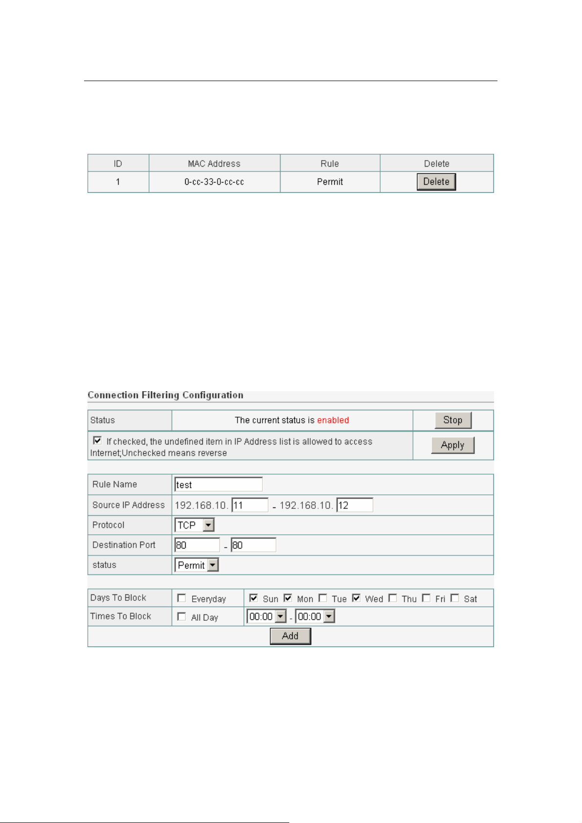
Figure 57
z If you want to remove some MAC address from the "Current Access Control
List ", select the MAC address you want to remove in the list and then click
"Delete ".
6.9.2 Access Control
If you want to restrict users from accessing certain Internet
applications/services (e.g. Internet websites, email, FTP etc.).This is the place
to set that configuration. Access Control allows users to define the traffic type
permitted in your LAN. You can control which PC client can have access to these
services.
Figure 58
Enable Access Control: To filter the outgoing packets for security or
management consideration by IP Address, either permitting or blocking access,
Page 46 of 54
Page 47
Wireless Broadband Router User manual
Enable Access Control is checked.
You can choose a default operation for your factual security or management
consideration:
The Undefined items beside the Rule list are PERMIT to access internet
DENIED to access internet.
The Undefined items beside the Rule list are DENIED to access internet
DENIED to access internet.
Rule Name: Enter the rule name which you want, it is just only a string.
Source IP: Enter the IP address of a station which is you want to setting.
Predefined Applications: Chose the Predefined rule in the list to be allowed or
forbade accessing Internet.
Protocol & Port: Chose protocol type (TCP/UDP) and enter the single port
number or the port range to allow or forbid.
Action: You can choose the rule is be allowed or forbade accessing Internet.
Figure 59
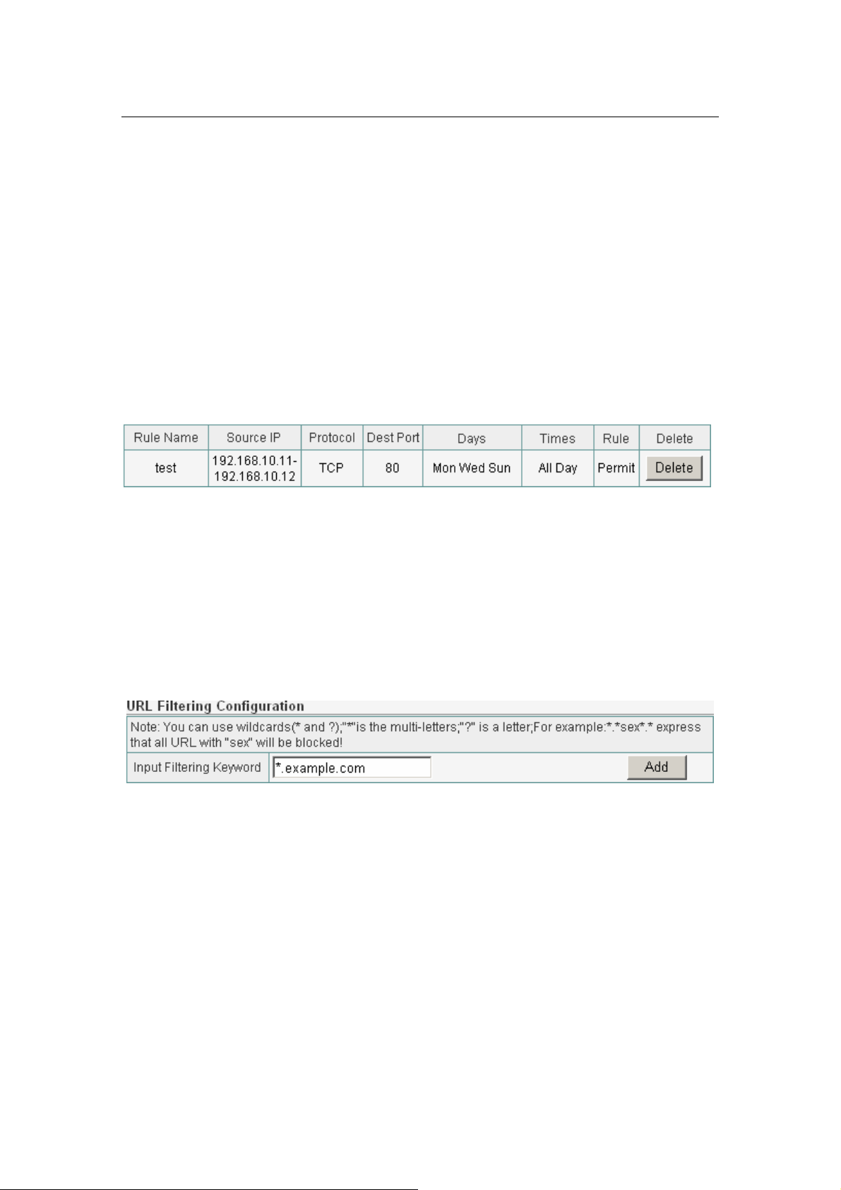
6.9.3 URL Filtering
URL (Uniform Resource Locator – e.g. an address in the form of
http://www.abcde.com or http://www.example.com) filter rules allow you to
prevent users on your network from accessing particular websites by their URL.
There are no pre-defined URL filter rules; you can add filter rules to meet your
requirements.
Figure 60
z Enable URL Fil tering: To enable or disable URL Filter feature. Enable URL
Filtering is checked.
z You can choose a default operation for your factual securi ty or management
consideration:
¾ Predefined URLs/Keywords in list are BLOCKED, others are PERMITTED.
¾ Predefined URLs/Keywords in list are PERMITTED, others are BLOCKED.
z URLs/Keywords: Enter the specified URL site for security or management
consideration by URLs/Keywords, either permitting or blocking access.
Page 47 of 54
Page 48

Wireless Broadband Router User manual
Figure 61
z Press “Delete” button to delete a rule after select a rule.
6.10 DDNS
DDNS allows you to map the static domain name to a dynamic IP address. You
must get an account, password and your static domain name from the DDNS
service providers.
Figure 62
z User ID/Password/Host Name: Enter your registered domain name
and your username and password for this service.
z Information: The status of the DDNS service connection is displayed here.
To see the latest DDNS status, click Refresh button.
6.11 MISC
6.11.1 Login ID & Password Setup
In factory setting, the default password is “N/A”, and that for user is also
password. You can change the default password to ensure that someone cannot
adjust your settings without your permission. Every time you change your
password, please record the password and keep it at a safe place.
Page 48 of 54
Page 49

Wireless Broadband Router User manual
Figure 63
z New Password. Enter your new password.
z Confirmed New Password: Enter your new password again for verification
purposes.
z Click “Apply” at the bottom of the screen to change the password.
If you forget your password, you’ll have to reset the router to the factory
default (Password is “N/A”) with the reset button (see router’s front panel).
6.11.2 Remote Mgmt
This feature allows you to manage the Router from a remote location, via the
Internet. To enable this feature, check the “Management Port” checkbox, and
click the Apply button.
Figure 64
z Management Port: Enter the port number.
z Click “Apply” at the bottom of the screen to change the Management Port.
When you want to access the web-based management from a remote site,
enter http:// WAN IP Address:8080. (e.g:http://192.168.10.1:8080
).
Figure 65
Page 49 of 54
Page 50

Wireless Broadband Router User manual
6.11.3 WAN Link Status & Setup
Figure 66
6.11.4 Restore Default / Restart System
Figure 67
Restore Default / Restart System
Restore the Router’s configuration to its factory default settings. Restore
Factory Defaults. To clear all of the Router’s settings and reset them to its
factory defaults.
z Click the Restore Default button. Router will restart automatically.
Restart System
Click "Restart System" button to reboot router.
Figure 68
6.11.5 Firmware Upgrade
Upgrade the Broadband router’s system firmware. To upgrade the firmware of
your Broadband router, you need to download the firmware file to your local
hard disk, and enter that file name and path in the appropriate field on this
page. You can also use the Browse button to find the firmware file on your PC.
Page 50 of 54
Page 51

Wireless Broadband Router User manual
Figure 69
Page 51 of 54
Page 52

Wireless Broadband Router User manual
Appendix Ⅰ: Troubleshooting
1. I cannot access the Web-based Configuration Utility from the
Ethernet computer used to configure the router.
z Check that the LAN LED is on. If the LED is not on, verify that the cable for
the LAN connection is firmly connected.
z Check whether the computer resides on the same subnet with the router’s
LAN IP address.
z If the computer acts as a DHCP client, check whether the computer has
been assigned an IP address from the DHCP server. If not, you will need to
renew the IP address.
z Use the ping command to ping the router’s LAN IP address to verify the
connection.
z Make sure your browser is not configured to use a proxy server.
z Check that the IP address you entered is correct. If the router’s LAN IP
address has been changed, you should enter the reassigned IP address
instead.
2. I forget Password (Reset the Router without Login)
z Plug out the power of the Router.
z Use a pencil to press and hold the default button on the back panel of the
Router. Plug in the power of the Router.
z Press and hold the default button wait for a few seconds until the CPU LED
indicator stays green.
z Reboot the AP.
z After the above those steps, the manufacture’s par ameters will be restored
in the Router. The default password is N/A.
3. I have some problems related to Connection with Cable
Modem please follow the following steps to check the problems:
z Check whether the DSL modem works well or the signal is stable. Normally
there will be some indicator lights on the modem, users can check whether
the signal is ok or the modem works well from those lights. If not, please
contact the ISP.
z Check the front panel of the Router, there are also some indicator lights
there. When the physical connection is correct, the Power light and the CPU
Page 52 of 54
Page 53

Wireless Broadband Router User manual
light should be solid; the WAN light should be blinking. If you use your
computer, the corresponding LAN port light should be blinking too. If not,
please check whether the cables work or not.
z Repeat the steps in WAN Setup Connect with Internet through DSL Modem.
4. I can browse the router’s Web-based Configuration Utility but
cannot access the Internet.
z Check if the WAN LED is ON. If not, verify that the physical connection
between the router and the DSL/Cable modem is firmly connected. Also
ensure the DSL/Cable modem is working properly.
z If WAN LED is ON, open the System Overview page of the Web
configuration utility and check the status group to see if the router’ s WAN
port has successfully obtained an IP address.
z Make sure you are using the correction method (Dynamic IP Address,
PPPoE, or Static IP) as required by the ISP. Also ensure you have entered
the correct settings provided by the ISP.
z For cable users, if your ISP requires a registered Ethernet card MAC address,
make sure you have cloned the network adapter’ s MAC address to the WAN
port of the router. (See the MAC Address field in WAN Setup.)
5. My wireless client cannot communicate with another Ethernet
computer.
z Ensure the wireless adapter functions properly. You may open the Device
Manager in Windows to see if the adapter is properly installed.
z Make sure the wireless client uses the same SSID and security settings (if
enabled) as the Wireless Broadband Router.
z Ensure that the wireless adapter’s TCP/IP settings are correct as required
by your network administrator.
z If you are using a 802.11b wireless adapter, and check that the 802.11G
Mode item in Wireless Basic Setting page, is not configured to use 802.11G
Performance.
z Use the ping command to verify that the wireless client is able to
communicate with the router’s LAN port and with the remote computer. If
the wireless client can successfully ping the router’ s LAN port but fails to
ping the remote computer, then verify the TCP/IP settings of the remote
computer.
Page 53 of 54
Page 54

Wireless Broadband Router User manual
Appendix : Ⅱ Features
Page 54 of 54
 Loading...