

Page 1

netis
Web Management Switch
User's Guide
Manual Version:1.1: 2015-03-12-1
1
Page 2

COPYRIGHT & TRADEMARKS
Specifications are subject to change without notice. NETIS is a registered trademark of NETCORE
Technologies Co., Ltd. Other brands and product names are trademarks or registered trademarks
of their respective holders.
No part of the specifications may be reproduced in any form or by any means or used to make
any derivative such as translation, transformation, or adaptation without permission from
NETCORE Technologies Co. Ltd. Copyright, All Rights Reserved.
FCC STATEMENT
Manual Description
This user guide is provided for using this type of switch. The manual includes the switch
performance and function. Please read this manual before managing the device:
Intended Audience
This guide is intended for network administrators familiar with IT concepts and network
terminology.
SAFETY NOTICES
Do not use this product near water, for example, in a wet basement or near a swimming pool.
Avoid using this product during an electrical storm. There may be a remote risk of electric shock
from lightning.
2
Page 3

TABLE OF CONTENTS
Chapter 1: Introduction ............................................................................................................. 4
1.1 Features .............................................................................................................................. 4
Technical Specifications ............................................................................................................ 4
Chapter 2: Mounting Device ..................................................................................................... 5
2.1 Installation Precautions....................................................................................................... 5
2.2 AC POWER ........................................................................................................................... 5
Chapter3: Login The Device ....................................................................................................... 5
3.1 configure the computer ...................................................................................................... 6
3.1.1 Windows XP ............................................................................................................. 6
3.1.2 Windows 7/Windows Vista ...................................................................................... 9
3.2 Check the connection ........................................................................................................ 12
3.3 Login the device ................................................................................................................ 13
3.4 Functional Overview ......................................................................................................... 14
Chapter4: System .................................................................................................................... 15
4.1 The Home page ................................................................................................................. 15
4.2 System Information ........................................................................................................... 15
4.2.1 IP Address ............................................................................................................... 16
4.2.2 User Account .......................................................................................................... 17
4.2.3 Port Setting ............................................................................................................ 18
4.3 Configuration .................................................................................................................... 18
4.3.1 Link Aggregation ..................................................................................................... 18
4.3.2 VLAN ....................................................................................................................... 19
4.3.3 QoS ......................................................................................................................... 23
4.3.4 Loop Prevention ..................................................................................................... 26
4.3.5 Port-based Mirroring.............................................................................................. 27
4.3.6 Port Isolation .......................................................................................................... 27
4.3.7 Bandwidth Control ................................................................................................. 28
4.3.8 Jumbo Frame .......................................................................................................... 29
4.3.9 MAC Constraint ...................................................................................................... 30
4.3.10 IGMP Snooping ..................................................................................................... 31
4.3.11 EEE ........................................................................................................................ 32
4.4 Security.............................................................................................................................. 33
4.4.1 MAC Address .......................................................................................................... 33
4.4.2 Storm Control Setting ............................................................................................. 35
4.5 Monitoring ........................................................................................................................ 36
4.5.1 Port Statistics ......................................................................................................... 36
3
Page 4

4.6 Tools .................................................................................................................................. 37
4.6.1 Backup Configuration ............................................................................................. 37
4.6.2 Reboot .................................................................................................................... 38
4.6.3 Save Configuration ................................................................................................. 39
4.6.4 Load Factory Default .............................................................................................. 40
4.6.5 Load Factory Default .............................................................................................. 41
Chapter 1: Introduction
1.1 Features
Support link aggregation.
Support port VLAN and IEEE 802.1Q VLAN.
Support rate limit, port statistics.
Support port mirroring.
Support QoS, providing strict priority.
Support Loop Prevention.
Support MAC Address binding.
Support storm control.
Support the port Isolation.
Support IGMP snooping, multicast probe.
Support WEB-based management.
Support WEB-based firmware upgrade.
Support parameter backup and recovery.
Technical Specifications
For simplicity, we take ST3208 as an example of the product images below.
The ST3208 front panel has 8 10/100M adaptive UTP ports, and the LED indicator. The 8 ports
support 10/100Mbps bandwidth connection device, auto-negotiation capability. Each port
corresponds to a set of indicator, LNK / ACT.
4
Page 5

Chapter 2: Mounting Device
2.1 Installation Precautions
Ensure the surface on which the device is placed is adequately secured to prevent it from
becoming unstable Ensure the power outlet is placed within 1.8m (6feet) of the device. Ensure
the device is connected safely to the power outlet with the AC power cable. Ensure the device
around good ventilation and heat dissipation
Do not place heavy objects on the device
2.2 AC POWER
The switch can be used with AC power supply 100 to 240V AC, 50 to 60Hz. Switch built-in power
supply system can be the actual input voltage automatically adjusts its operating voltage. The
power connector is located on the rear panel switch.
Disconnect the power cord is a plug on the power switch on the rear panel interface, the other
end plugged into a power outlet.
Chapter3: Login The Device
You can use the web browser-based configuration to manage ST3208. ST3208 to be configured
through a web browser, at least a reasonable allocation of computer through an Ethernet
connection to ST3208.
Figure 3-1
The machine-default IP address is 192.168.2.11, subnet mask is 255.255.255.0. So when you log
on to the switch, make sure the IP address of the computer network card and the IP of the switch
5
Page 6

in the same network segment: 192.168.2. *** (1 <*** <255, *** is not equal to 11). Reference to
the following steps to set up:
3.1 configure the computer
The Management switch is managed via WEB pages. The smart and friendly interfaces make the
switch management an easy job. Due to the difference of Operating system, the WEB page
display may differ between variable Operating System
3.1.1 Windows XP
Follow these steps to configure your computer:
1.Start-Control Panel
Figure 3-1-1
2. Click ”Network and Internet Connection”.
6
Page 7

Figure 3-1-2
3.Click ”network connections”.
Figure 3-1-3
4.click right-hand button on the adapter icon and click “Properties”.
7
Page 8
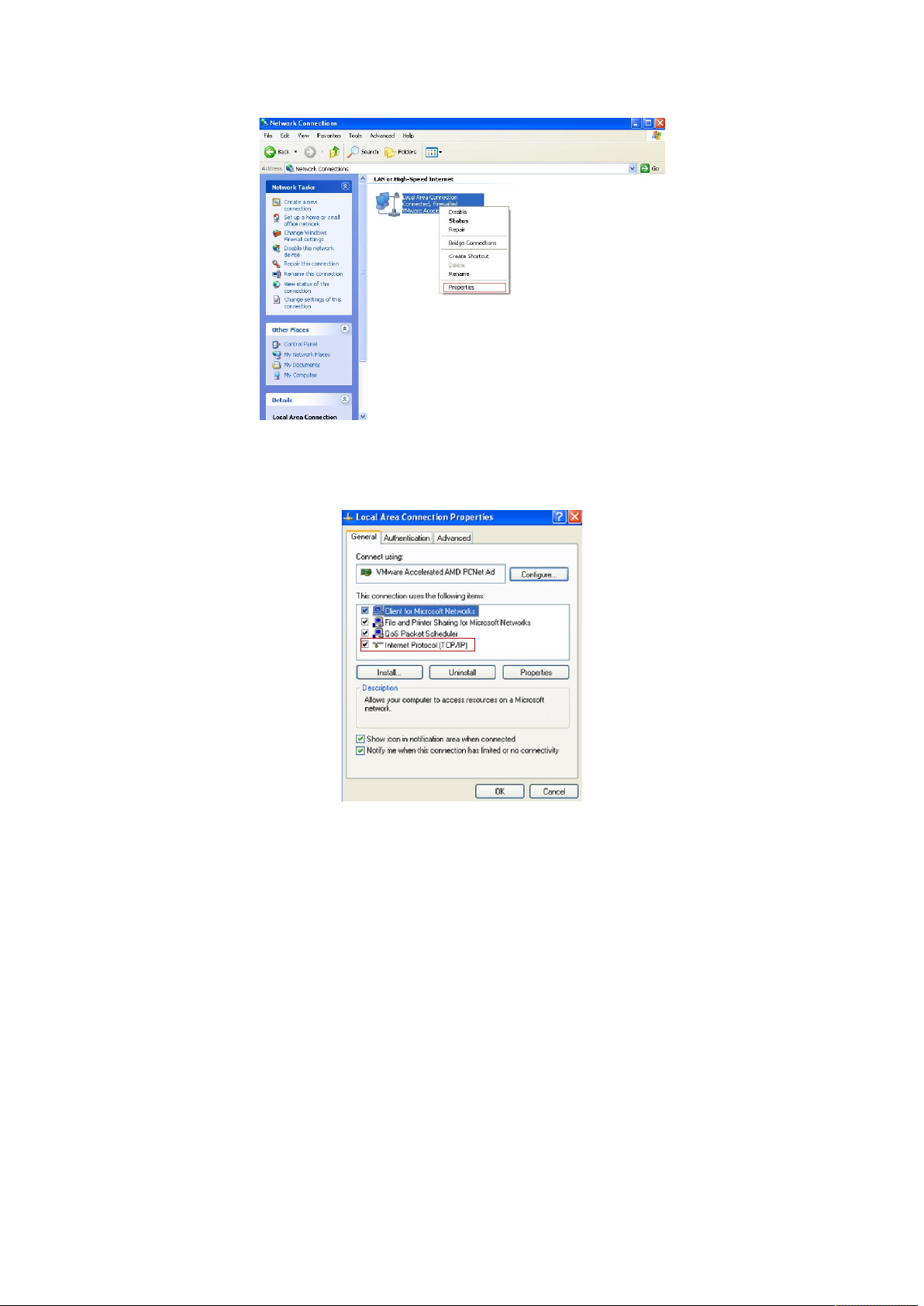
Figure 3-1-4
5.Double-click “Internet Protocol (TCP/IP)”.
Figure 3-1-5
6.Use the following IP address: enter the IP address 192.168.2. *** (1 <*** <255, *** does not
equal 11,because the default IP address of the switch is 192.168.2.11) , subnetmask
255.255.255.0, default gateway and preferred DNS server is optional and then click OK to close
the Internet Protocol (TCP / IP) properties window.
8
Page 9
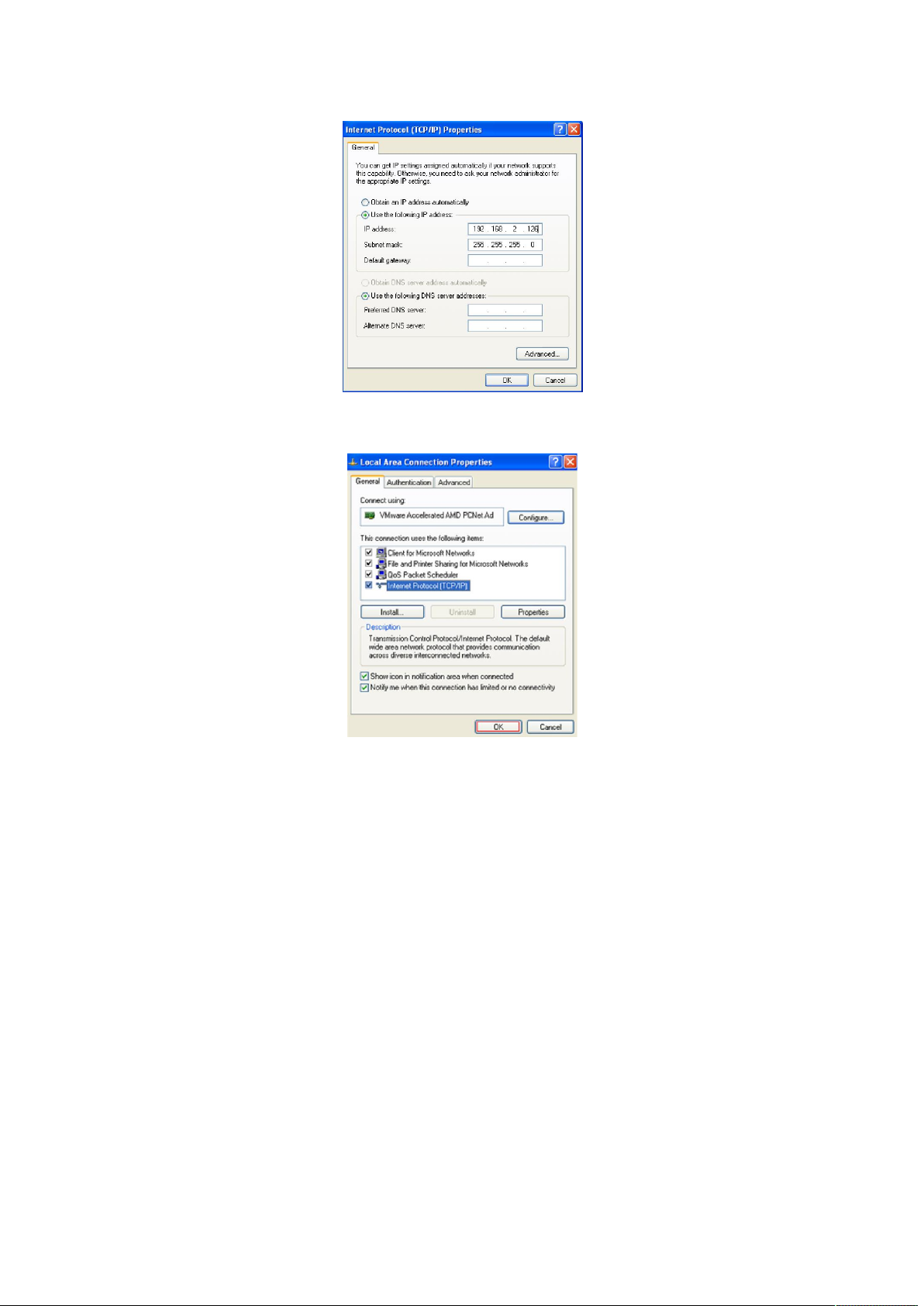
Figure 3-1-6
7.Click “OK” and Close the Local Area Connection Properties window.
Figure 3-1-7
3.1.2 Windows 7/Windows Vista
Follow these steps to configure your computer
1、Start-Control Panel
9
Page 10
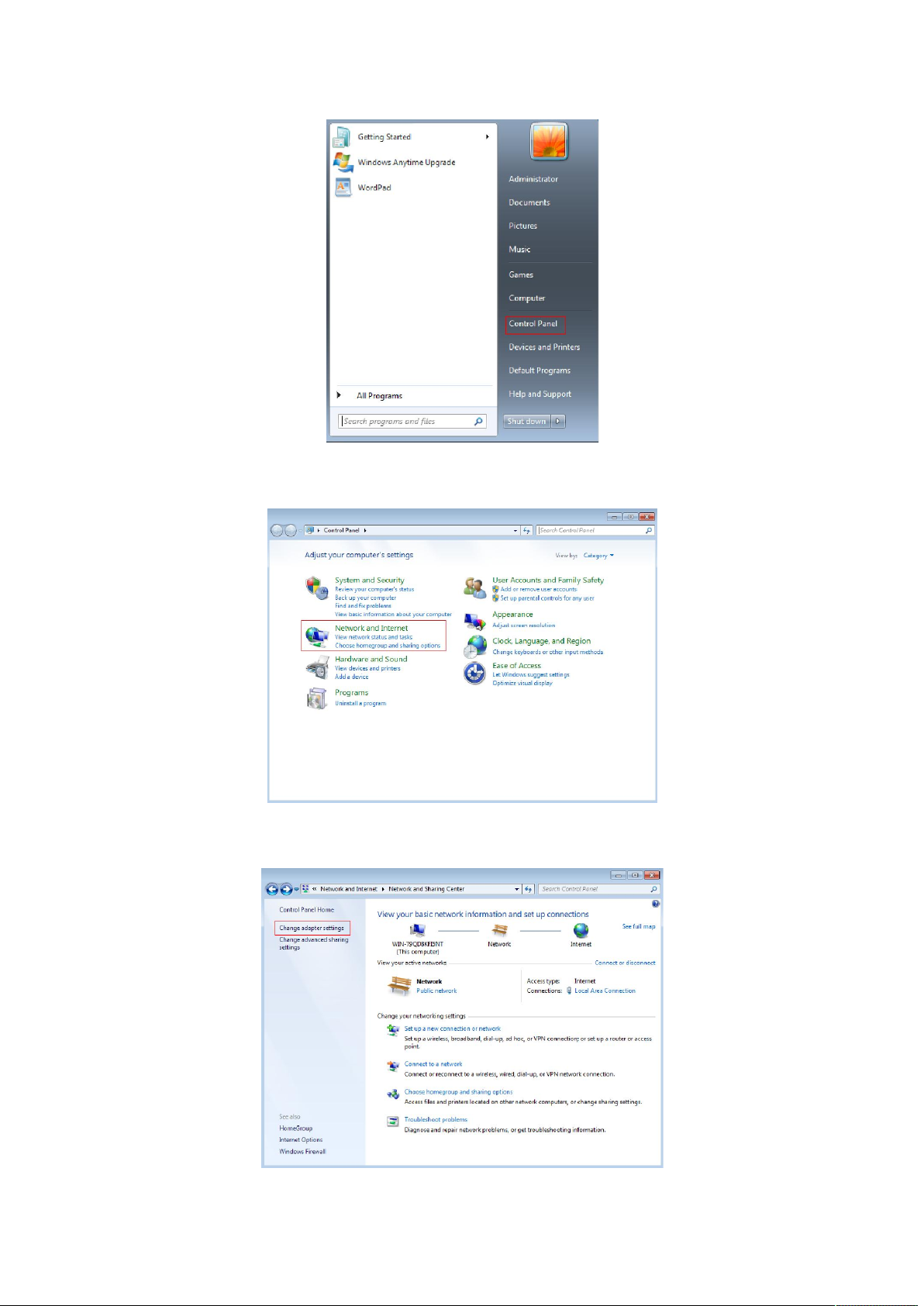
2、Click “Network and Internet ”
3、Click “Change adapter settings”
Figure 3-1-8
Figure 3-1-9
10
Page 11
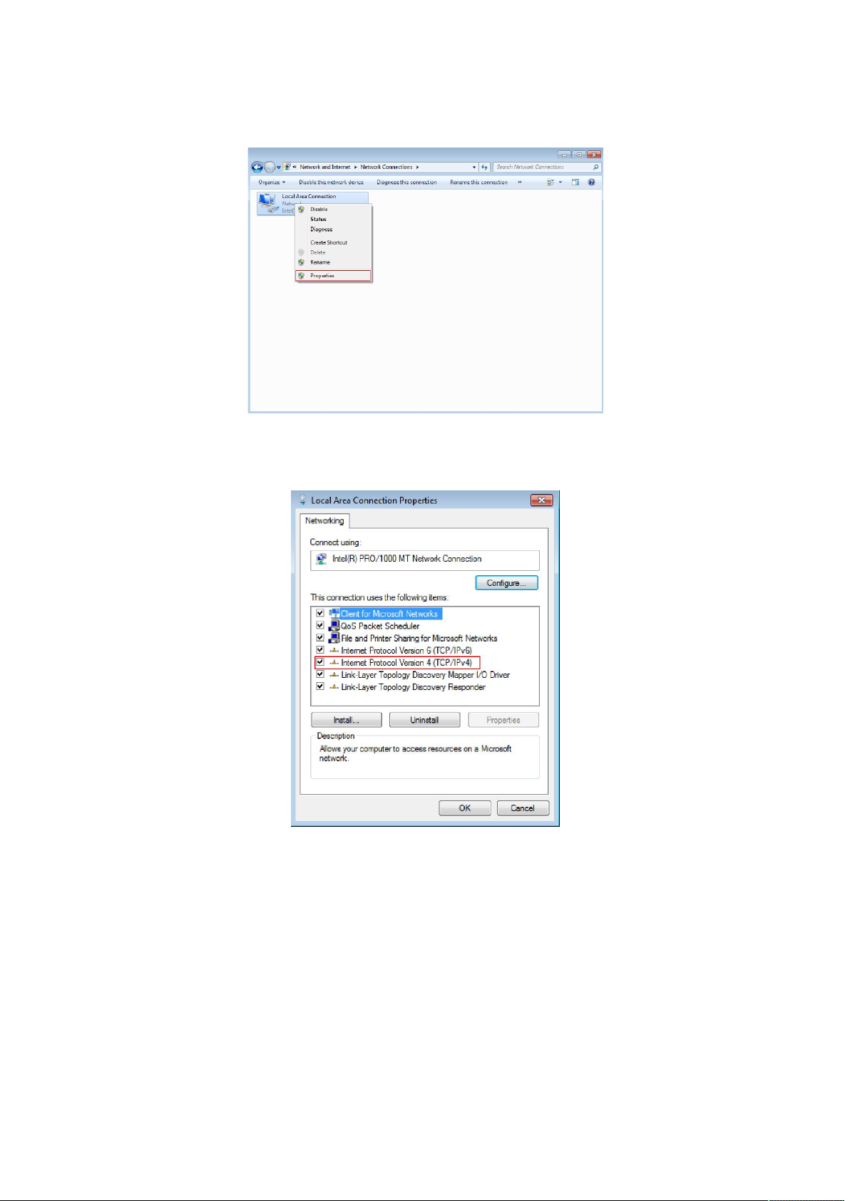
Figure 3-1-10
4. Click right-hand button on the adapter icon and click “Properties”
Figure 3-1-11
5.Double click “Internet protocol Version 4(TCP/IPv4)”
Figure 3-1-12
5、Use the following IP address: enter the IP address 192.168.2. *** (1 <*** <255, *** does not
equal 11, because the default IP address of the switch is
192.168.2.11) , subnetmask 255.255.255.0, default gateway and preferred DNS server is optional
and then click OK to close the Internet Protocol (TCP / IP) properties window.
11
Page 12
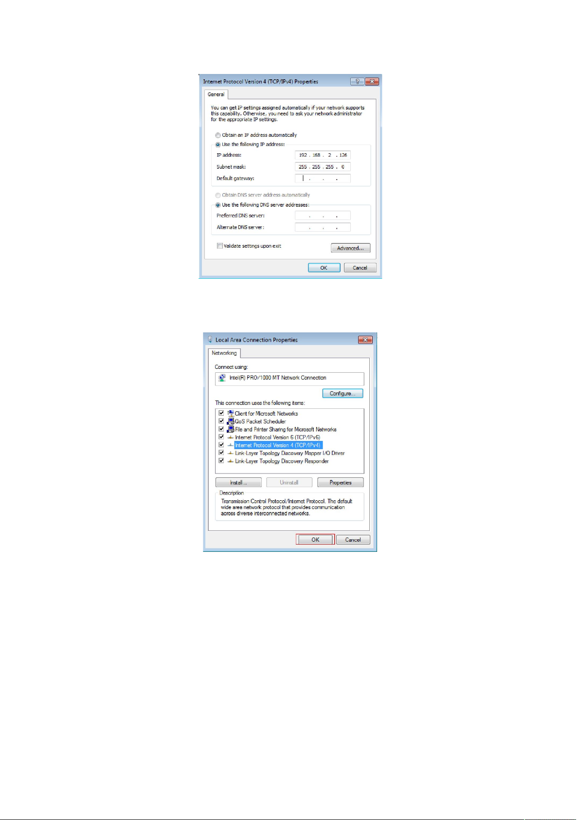
Figure 3-1-13
6、Click “OK” and Close the Local Area Connection Properties window
Figure 3-1-14
Notes:
Visa system configuration please refer to 3.1.4.
3.2 Check the connection
After setting the TCP / IP protocol, you can use the Ping command to verify whether the
computer can communicate with ST3208. To perform a ping command, open a command
window, the IP address in the command prompt where the Ping ST3208
12
Page 13

Windows XP,START-Control,type cmd in the search bar and press Enter
Windows 7,click Start, type cmd in the search bar and press Enter
where the DOS prompt, enter the following command
If the command window return to something like the following:
Figure 3-2-1
Then Connection between ST3208 and computer is successful
If the computer failed to connect on of ST3208, the command window will return the following
content.
Figure 3-2-2
Then make sure that your computer's network settings are correct and the cable is intact.
Caution:
YOU need to use a twisted pair to connect the port of your computer's network card to the
switch port before entering the above command
3.3 Login the device
1、Open IE browser, enter http://192.168.2.11 in the address bar, then return.
13
Page 14

Figure 3-3-1
2、In the pop-up window to enter user name: guest, password: guest, then press the OK button
Figure 3-3-2
NOTES:
If you are successful login into the switch webpage, the page from time to time automatically
refresh, allowing you to dynamically view the port status.
3.4 Functional Overview
The ST3208 switch have rich feature ,including the functions of system management, Port
Management, Redundancy management, Security management , QoS management, Network
Analysis, next chapter will introduce you these functions.
Figure 3-4-1
14
Page 15

Chapter4: System
4.1 The Home page
After logging into the switch, the main page appears as the following. It contains three parts:
Figure 4-1-1
zone"1":The Port table lies at the top of the page. It provides a visual representation of the
ports. The green icon indicates that the port is linked; the gray icon indicates that the port is not
linked;
zone"2":On the left side of the page is the menu table. It contains 5 main menus. Each menu has
some submenus. Click on a menu, it will open its submenus and the main window.
zone"3":The main part of the page is the main window to display the configuration page.
4.2 System Information
Click on the "System" ,the switch manage page will show as figure below, The system submenu
15
Page 16

have basic information, including: Information, IP Address, User Account, Port Setting. The
following picture is the detailed description.
Figure 4-2-1
The System Information shows the system information of the switch, such as Device Type, MAC
address, IP Address, Hardware and Software version information.
4.2.1 IP Address
Figure 4-2-2
16
Page 17
On this page you can manually set the IP address, subnet mask, gateway and other information;
can also use your network, among other DHCP SERVER switch automatically assigns an IP address.
The switch default IP address is: 192.168.2.11 default subnet mask: 255.255.255.0 Default
Gateway: no. When finished editing, click the "Apply" to complete the IP address settings.
Notes:
(1)When you select "DHCP Settings" is disabled, the switch will have to manually assign an IP
address.
(2)When DHCP client is enabled, the IP parameters are obtained automatically from the DHCP
server.
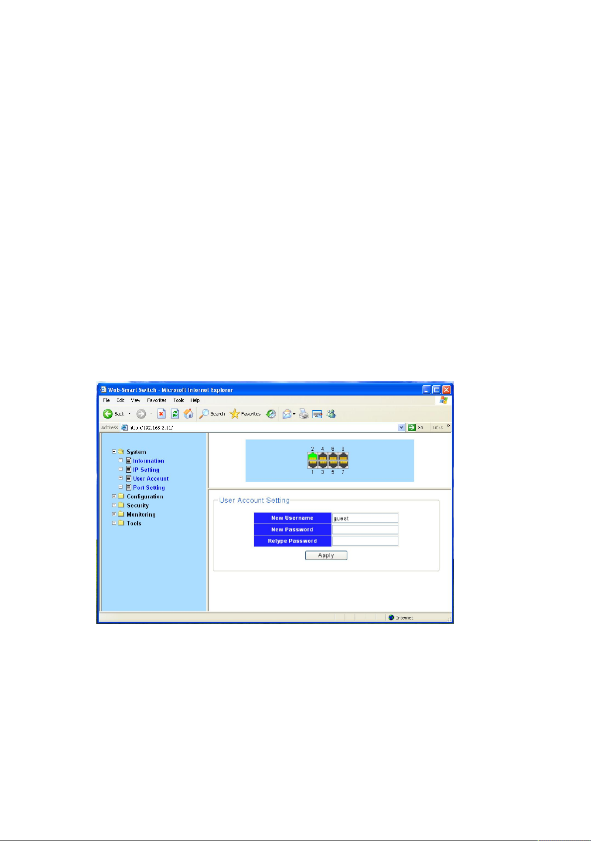
4.2.2 User Account
This page provides the interface of configuring username and password.
Figure 4-2-3
You are kindly suggested to retype the new password in "Confirm new password" box instead of
copying in order to avoid typing mistakes.
Caution:
Only letters, numbers and punctuations can be input into username and password. The other
characters are considered illegal. The initial password is guest.
17
Page 18

Notes:
After modifying the password with immediate effect, the parameters will not be lost though is
powered off.
4.2.3 Port Setting
Figure 4-2-4
On this page, you can configure the basic parameter for the ports .When the port is disabled, the
packers on the port will be discard. Shut down the port which is vacant for a long time can
reduce the power consumption effectively. And you can enable the port when it is in need. The
parameters will affect the working mode of the ports, please set the parameters appropriate.
Status: Allows you to Enable/Disable the port .When Enable is set, the port can forward the
packets normally.
Speed and Duplex: Select the speed and Duplex mode for the port .The device connected to the
switch should be in the same Speed and Duplex mode with the switch .When “Auto” is set, the
Speed and Duplex mode will be determined by auto-negotiation. But the SFP port, this Switch
does not support auto-negotiation.
Flow Control: Allows you to Enable /Disable the Flow Control feature .When Flow Control is
enabled, the switch can synchronize the speed with its peer to avoid the congestion.
4.3 Configuration
4.3.1 Link Aggregation
Link Aggregation is to combine a number of ports together to make a single high-bandwidth data
18
Page 19
path, so as to implement the traffic load sharing among the member ports in the group and to
enhance the connection reliability.
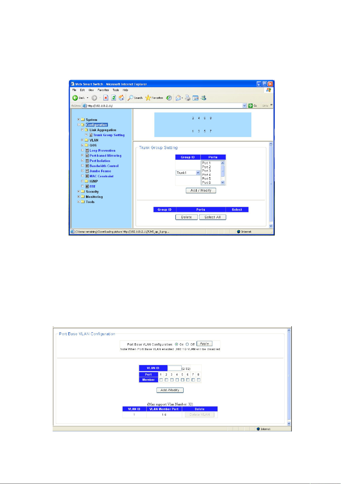
Figure 4-3-1
Select an aggregation group number, then add port in the left form to the right form, that make
port join into aggregation group. ST3208 has max 4 groups, and one aggregation group can
support max 8 member ports.
4.3.2 VLAN
Figure 4-3-2
19
Page 20

Introduction to VLAN
The traditional Ethernet is a broadcast network, where all hosts are in the same broadcast
domain and connected with each other through hubs or switches. Hubs and switches, which are
the basic network connection devices, have limited forwarding functions.
A hub is a physical layer device without the switching function, so it forwards the received
packet to all ports except the inbound port of the packet.
A switch is a link layer device which can forward a packet according to the MAC address of
the packet. A switch builds a table of MAC addresses mapped to associated ports with that
address and only sends a known MAC’s traffic to one port. When the switch receives a
broadcast packet or an unknown unicast packet whose MAC address is not included in the
MAC address table of the switch, it will forward the packet to all the ports except the
inbound port of the packet. The above scenarios could result in the following network
problems.
Large quantity of broadcast packets or unknown unicast packets may exist in a network,
wasting network resources.
A host in the network receives a lot of packets whose destination is not the host itself,
causing potential serious security problems.
Related to the point above, someone on a network can monitor broadcast packets and
unicast packets and learn of other activities on the network. Then they can attempt to
access other resources on the network, whether or not they are authorized to do this.
Isolating broadcast domains is the solution for the above problems. The traditional way is to use
routers, which forward packets according to the destination IP address and does not forward
broadcast packets in the link layer. However, routers are expensive and provide few ports, so
they cannot split the network efficiently. Therefore, using routers to isolate broadcast domains
has many limitations.
The Virtual Local Area Network (VLAN) technology is developed for switches to control
broadcasts in LANs.
A VLAN can span multiple physical spaces. This enables hosts in a VLAN to be located in different
physical locations. By creating VLANs in a physical LAN, you can divide the LAN into multiple
logical LANs, each of which has a broadcast domain of its own. Hosts in the same VLAN
communicate in the traditional Ethernet way. However, hosts in different VLANs cannot
communicate with each other directly but need the help of network layer devices, such as
routers and Layer 3 switches.
Advantages of VLANs
Compared with traditional Ethernet technology, VLAN technology delivers the following benefits:
Confining broadcast traffic within individual VLANs. This saves bandwidth and improves
network performance.
20
Page 21
Improving LAN security. By assigning user groups to different VLANs, you can isolate them at
Layer 2. To enable communication between VLANs, routers or Layer 3 switches are
required.
Flexible virtual workgroup creation. As users from the same workgroup can be assigned to
the same VLAN regardless of their physical locations, network construction and
maintenance is much easier and more flexible.
4.3.2.1 VLAN Configure
Port Base VLAN
On this page you can configure the Port Base VLAN.
Choose the menu Configuration →VLAN →Port base VLAN to load the following page.
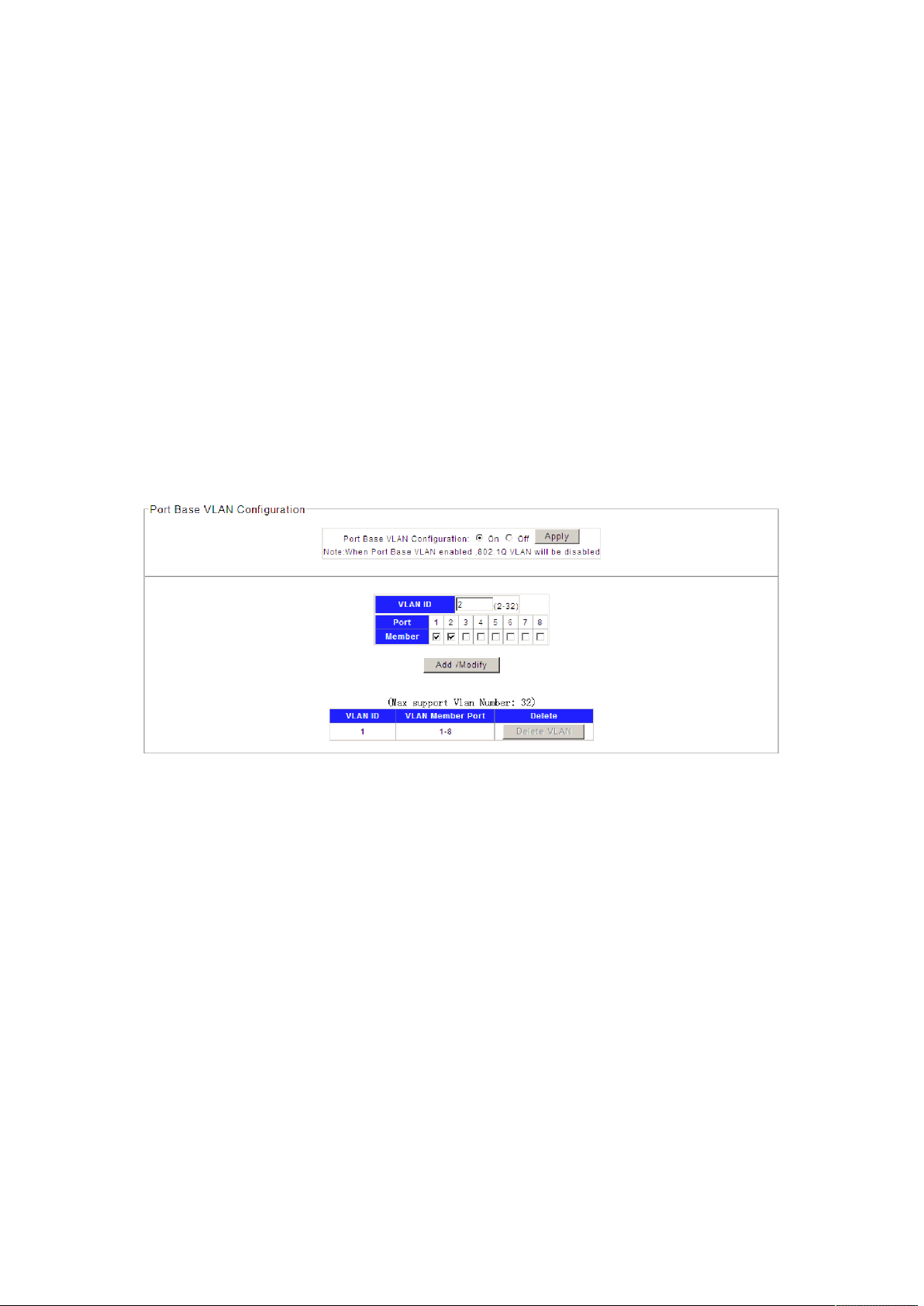
Here configure port 1 and 2 into VLAN 2 e.g.
Figure 4-3-3
Port Based VLAN is enable by default.
1. Specify the Port- Base VLAN ID that need to configure..
2. Select the desired port which joined into the Port-Base VLAN.
3. Click Add/Modify to create the VLAN.
802.1Q VLAN
1. Choose the menu Configuration →VLAN →Port Base VLAN to load Port Base VLAN page.
Then disable Port Base VLAN on this page first, this can enable 802.1Q VLAN.
21
Page 22
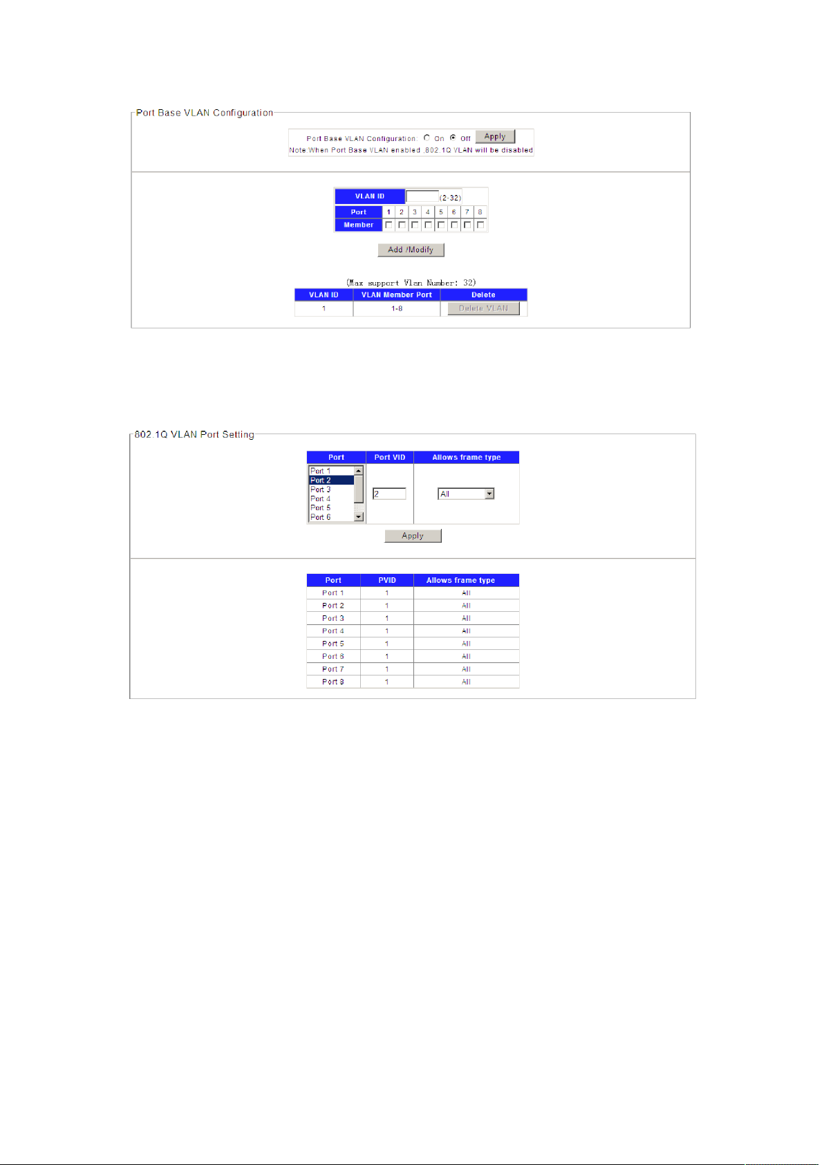
Figure 4-3-4
2. Choose the menu Configuration →VLAN →802.1Q PVID to load the following page.
Configure PVID on this page.
Figure 4-3-5
1). Select the desired port which to set PVID. Here is port 2 e.g.
2). Specify the PVID number of this port. Here is VLAN 2 e.g.
3). Select the frame type allowed of this port: ALL, Only with tag or Only no with tag.
4). Click Apply to change PVID of port 2.
3. Choose the menu Configuration →VLAN →802.1Q VLAN to load the following page.
Configure 802.1Q VLAN member port on this page.
Here configure port 2 as access=2, port 1,3 as trunk =2 e.g.
22
Page 23
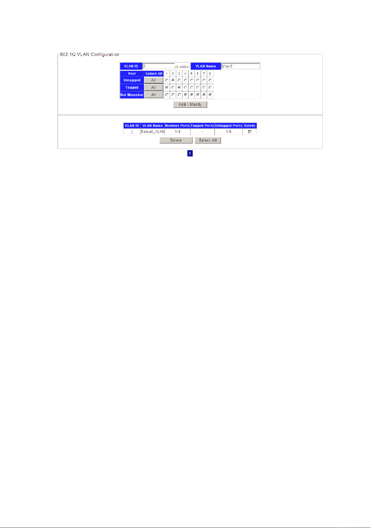
Figure 4-3-6
1). Specify the VLAN ID need to configure. Here is VLAN 2 e.g.
2). Specify the VLAN Name of VLAN 2.Here is VLAN2.
3). Select the member port of VLAN 2, and frame type supported: Untagged or Tagged. Select
port 2 as Untagged. Select port 1,3 as Tagged e.g.
4). Click Add/Modify to set VLAN member port.
4.3.3 QoS
QoS (Quality of Service) functions to provide different quality of service for various network
applications and requirements and optimize the bandwidth resource distribution so as to provide
a network service experience of a better quality.
23
Page 24
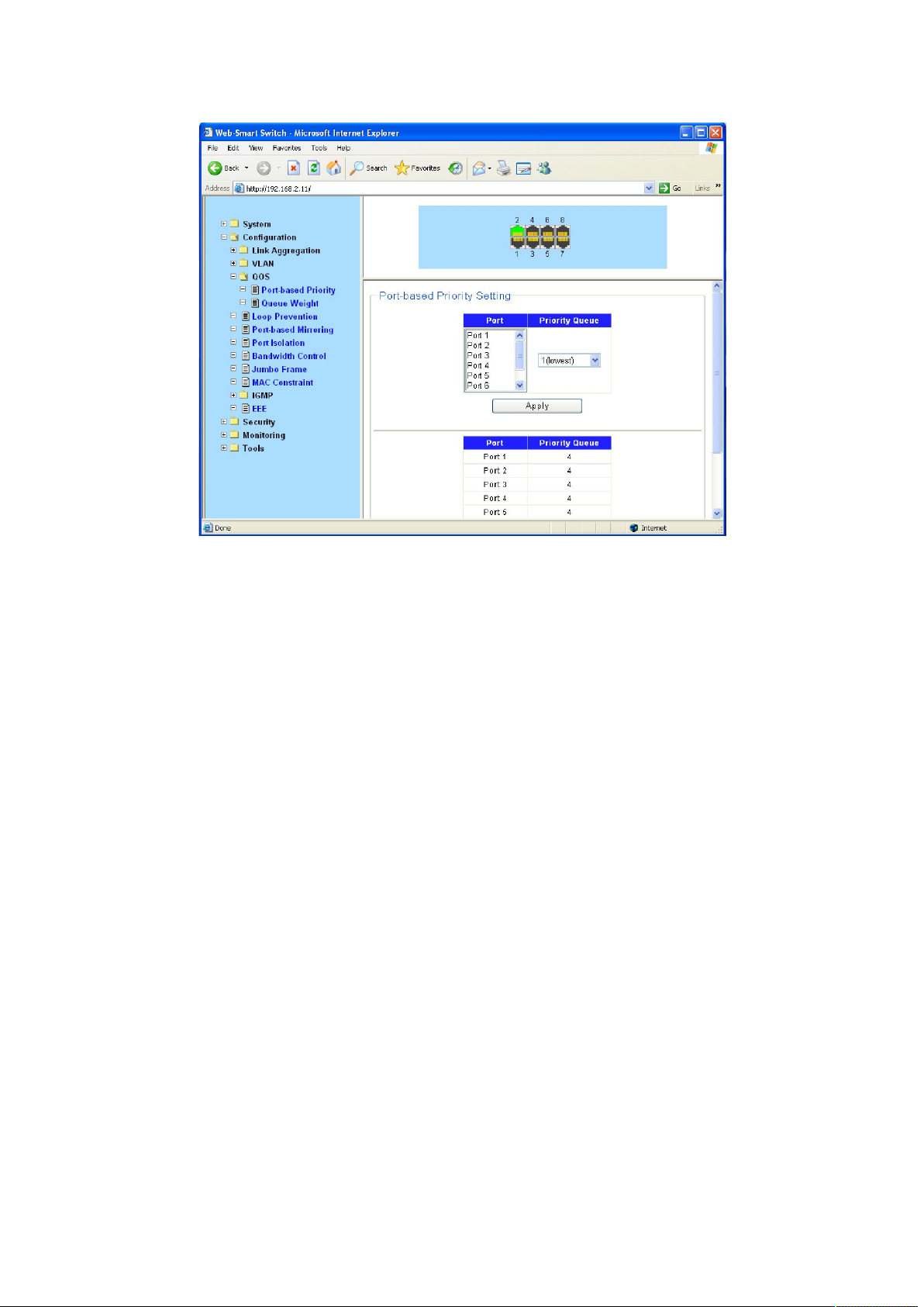
Figure 4-3-7
QoS
This switch classifies the ingress packets, maps the packets to different priority queues and then
forwards the packets according to specified scheduling algorithms to implement QoS function.
Traffic classification: Identifies packets conforming to certain characters according to certain
rules.
Map: The user can map the ingress packets to different priority queues based on the priority
modes. This switch implements priority modes based on port.
Queue scheduling algorithm: When the network is congested, the problem that many packets
compete for resources must be solved, usually in the way of queue scheduling. The switch
supports four schedule modes: SP.
Priority Mode
This switch implements three priority modes based on port, on 802.1P and on DSCP. By default,
the priority mode based on port is enabled and the other two modes are optional.
Port Priority
Port priority is a priority level of the port. After port priority is configured, the data stream will be
mapped to the egress queues directly according to the priority level of the port.
24
Page 25
Schedule Mode
When the network is congested, the problem that many packets compete for resources must be
solved, usually in the way of queue scheduling. The switch implements four scheduling queues.
SP-Mode: Strict-Priority Mode. In this mode, the queue with higher priority will occupy the whole
bandwidth. Packets in the queue with lower priority are sent only when the queue with higher
priority is empty. The switch has four egress queues labeled. The disadvantage of SP queue is
that: if there are packets in the queues with higher priority for a long time in congestion, the
packets in the queues with lower priority will be “starved to death” because they are not served.
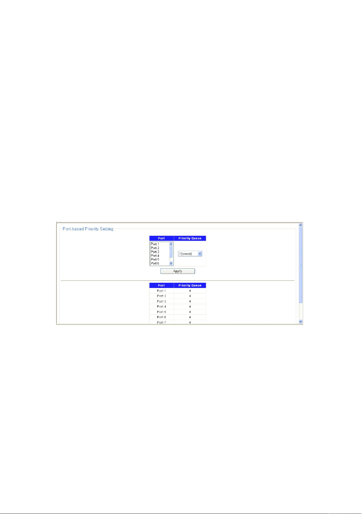
4.3.3.1 QoS Configure
Port Priority
On this page you can configure the port priority.
Choose the menu Configuration →QoS →Port-based Priority to load the following page.
Figure 4-3-8
1. Displays the physical port number of the switch.
2. Select the desired port to configure its priority.
3. Specify the priority for the port.
25
Page 26

4.3.4 Loop Prevention
Figure 4-3-9
With loop prevention feature enabled, the switch can prevention loops using loop-prevention
packets. When a loop is detected, the switch will display an alert or further block the
corresponding port according to the port configuration.
Choose the menu Configuration →Loop Prevention → Loop Prevention to load the following
page.
Figure 4-3-10
26
Page 27

4.3.5 Port-based Mirroring
Port mirroring allows you to duplicate the packets passing specified ports to the destination
mirroring port. As destination mirroring ports usually have data monitoring devices connected to
them, you can analyze the packets duplicated to the destination mirroring port on these devices
so as to monitor and troubleshoot the network.
Figure 4-3-11
Choose the menu Configuration→ Port-based Mirroring to load the following page.
Select the Source Port from where you want to copy frames and the Target Port, which receives
the copies from the source port.
1. Change the Port-base Mirroring Status menu to On.
2. Click Apply to let the changes take effect.
3. Select the Source Direction, Ingress, Egress.
4.3.6 Port Isolation
To implement isolation, you can add different ports to different VLANs. However, this will waste
the limited VLAN resource. With port isolation, the ports can be isolated within the same VLAN.
Thus, you need only to add the ports to the isolation group to implement isolation. This provides
27
Page 28

you with more secure and flexible networking schemes.
Choose the menu Configuration→ Port Isolation to load the following page.
Figure 4-3-12
On the current device:
Currently, only one isolation group is supported on a device, which is created automatically
by the system as isolation group. The user cannot remove the isolation group or create
other isolation groups.
The number of the ports an isolation group can contain is not limited.
4.3.7 Bandwidth Control
Rate limit functions to control the ingress/egress traffic rate on each port via configuring the
available bandwidth of each port. In this way, the network bandwidth can be reasonably
distributed and utilized.
Choose the menu Configuration→ Bandwidth Control to load the following page.
28
Page 29

Figure 4-3-13
If you select port to set ingress/egress rate, the system will automatically select integral multiple
of 16Kbps that closest to the rate you entered as the real ingress/egress rate.
Ingress: Configure the bandwidth for receiving packets on the port. You can select a port to set
Ingress rate, the system will automatically select integral multiple of 16Kbps that closest to the
rate you entered as the real Ingress rate.
Egress: Configure the bandwidth for sending packets on the port. You can select a port to set
Egress rate, the system will automatically select integral multiple of 16Kbps that closest to the
rate you entered as the real Egress rate.
4.3.8 Jumbo Frame
Due to tremendous amount of traffic occurring in Ethernet, it is likely that some frames might
have a frame size greater than the standard Ethernet frame size. By allowing such frames (called
jumbo frames) to pass through Ethernet ports, you can forward frames with a size greater than
the standard Ethernet frame size and yet still within the specified parameter range.
Choose the menu Configuration→ Jumbo Frame to load the following page.
29
Page 30

Figure 4-3-14
You can set the length of jumbo frames that can pass through all the Ethernet ports.
By default, the device allows jumbo frames with the length of 1522/1536/1552/2048 bytes to
pass through all Ethernet ports.
4.3.9 MAC Constraint
MAC address learning capability, you can setting of maximum number of MAC addresses that can
be learned on the port Forwarding of frames with unknown destination MAC addresses after the
upper limit of the MAC address table is reached.
Choose the menu Configuration→MAC Constraint to load the following page.
30
Page 31

Figure 4-3-15
4.3.10 IGMP Snooping
Internet Group Management Protocol Snooping (IGMP Snooping) is a multicast constraining
mechanism that runs on Layer 2 devices to manage and control multicast groups.
The switch, running IGMP Snooping, listens to the IGMP messages transmitted between the host
and the router, and tracks the IGMP messages and the registered port. When receiving IGMP
report message, the switch adds the port to the multicast address table; when the switch listens
to IGMP leave message from the host, the router sends the Group-Specific Query message of the
port to check if other hosts need this multicast, if yes, the router will receive IGMP report
message; if no, the router will receive no response from the hosts and the switch will remove the
port from the multicast address table. The router regularly sends IGMP query messages. After
receiving the IGMP query messages, the switch will remove the port from the multicast address
table if the switch receives no IGMP report message from the host within a period of time.
31
Page 32
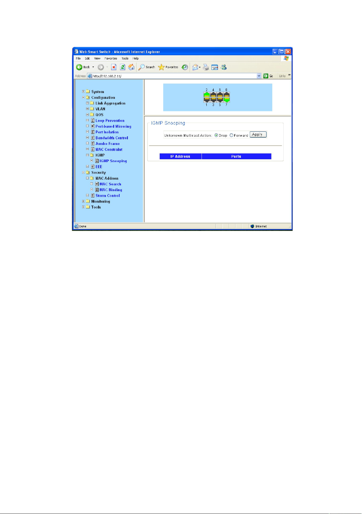
Figure 4-3-16
Unknown multicast data refers to multicast data for which no entries exist in the IGMP Snooping
forwarding table. When the switch receives such multicast traffic:
With the function of dropping unknown multicast data, the switch drops all the unknown
multicast data received.
With the function of forwarding unknown multicast data, the switch floods unknown
multicast data in the VLAN which the unknown multicast data belongs to.
4.3.11 EEE
The switch supports IEEE 802.3az Energy Efficient Ethernet (EEE) for 100Base-TX in full duplex
operation, and supports 10Base-Te for 10Base-T in full/half duplex. The Energy Efficient Ethernet
(EEE) operational mode combines the IEEE 802.3 Media Access Control (MAC) Sub-layer with a
family of Physical Layers defined to Support operation in Low Power Idle (LPI) Mode. When Low
Power Idle Mode is enabled, systems on both sides of the link can disable portions of the
functionality and save power during periods of low link utilization.
The switch EEE operational mode supports IEEE 802.3 MAC operation at 100Mbps. For 100Mbps
operation, the 100Base-TX PHY is supported. In addition, the switch supports a 10Mbps PHY with
reduced transmit amplitude requirements in EEE operational mode. This new PHY is fully
interoperable with legacy 10Base-T PHYs over 100m of Class-D (Category 5) or better cabling.
32
Page 33

Figure 4-3-17
4.4 Security
4.4.1 MAC Address
A switch maintains a MAC address table for frame forwarding. Each entry in this table contains
the MAC address of a connected device, to which port this device is connected and to which
VLAN the port belongs.
4.4.1.1 MAC Search
A MAC address table consists of two types of entries: static and dynamic. Static entries are
manually configured and never age out. Dynamic entries can be manually configured or
dynamically learned and may age out.
33
Page 34
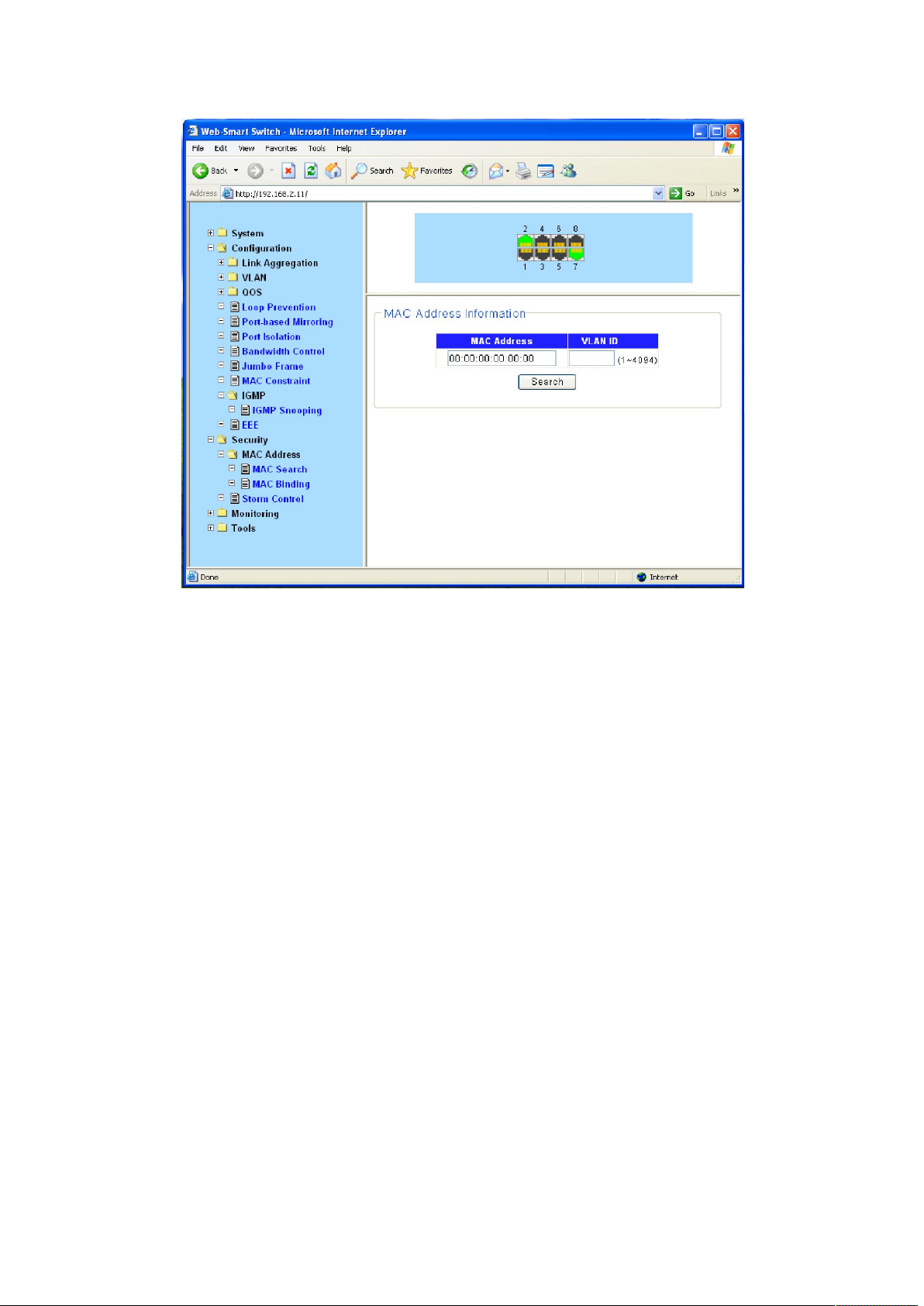
Figure 4-3-18
Find Allows the user to move to a sector of the database corresponding to a user
defined port, VLAN, or MAC address.
VID The VLAN ID of the VLAN the port is a member of.
MAC Address The MAC address entered into the address table.
Port The port that the MAC address above corresponds to.
4.4.1.2 MAC Binding
The static address table maintains the static address entries which can be added or removed
manually. In the stable networks, the static MAC address entries can facilitate the switch to
reduce broadcast packets and remarkably enhance the efficiency of packets forwarding without
learning the address. The static MAC address learned by the port in the binding mode will be
displayed in the Static Address Table.
34
Page 35
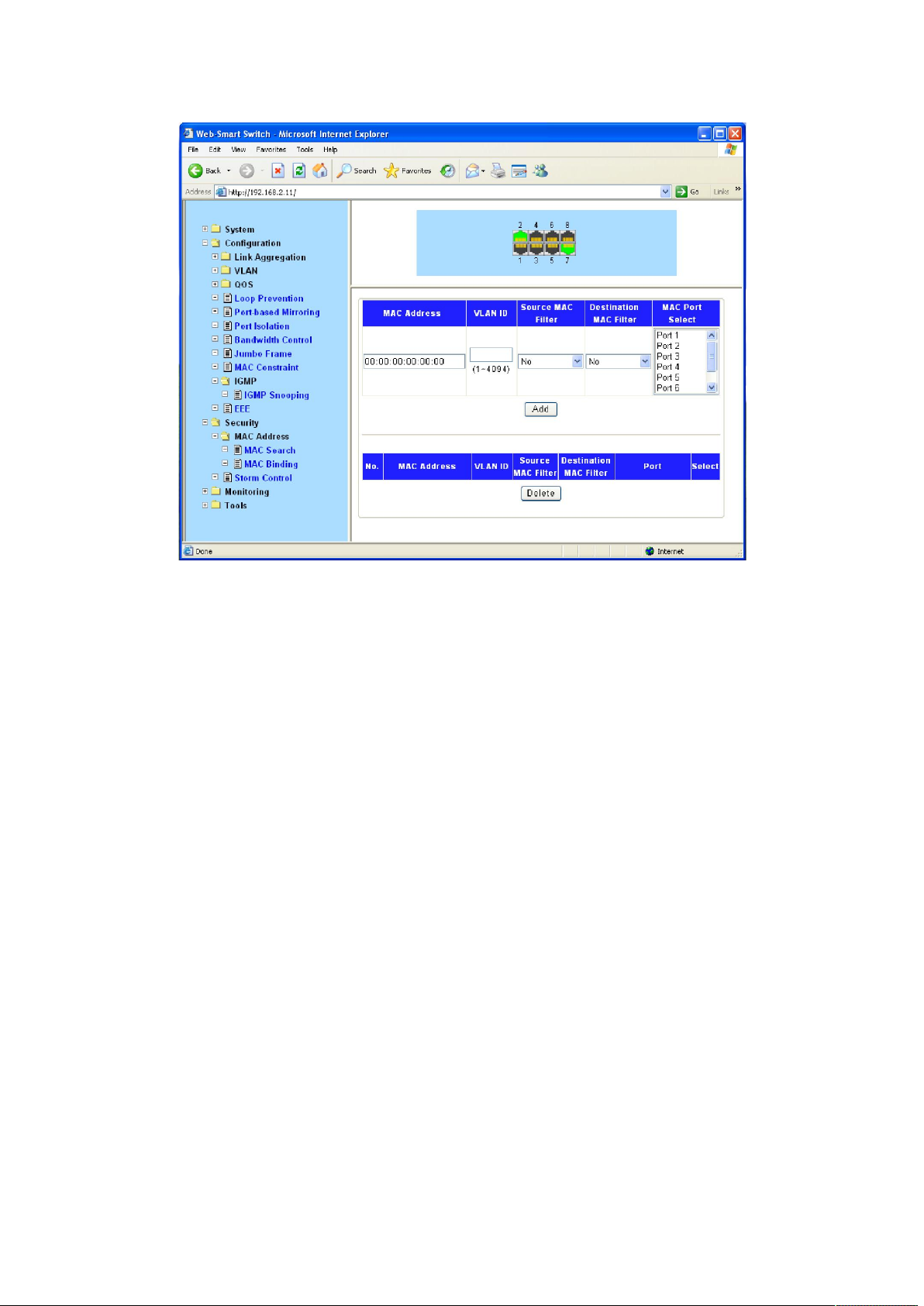
Figure 4-3-19
4.4.2 Storm Control Setting
Storm Control function allows the switch to filter Broadcast, Multicast and Unknown Unicast
frame in the network. If the transmission rate of the three kind packets exceeds the set
bandwidth, the packets will be automatically discarded to avoid network broadcast storm.
Choose the menu Security→Storm Control to load the following page.
35
Page 36
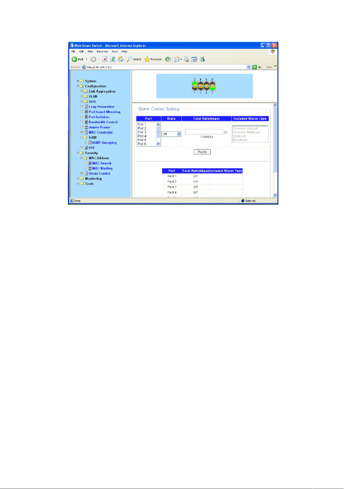
Figure 4-3-20
Storm control is used to stop broadcast, multicast or ARP request storms that may result when a
loop is created. The Destination Look Up Failure control is a method of shutting down a loop
when a storm is formed because a MAC address cannot be located in the Switch’s forwarding
database and it must send a packet to all ports or all ports on a VLAN.
To configure Traffic Control, select the port, you want to configure. Broadcast Storm, Multicast
Storm and Unknown Unicast may be Enabled or Disabled. The Threshold value is the upper
threshold at which the specified traffic control is switched on. This is the number of Broadcast,
Multicast or Unknown Unicast packets, in Kbps, received by the switch that will trigger the storm
traffic control measures. The Threshold value can be set from 0 to100000Kbps.
4.5 Monitoring
4.5.1 Port Statistics
The Traffic Monitor function, monitoring the traffic of each port, is implemented on the Traffic
Summary and Traffic Statistics pages.
Traffic Summary screen displays the traffic information of each port, which facilitates you to
monitor the traffic and analyze the network abnormity.
Choose the menu Monitoring→ Port Statistics to load the following page.
36
Page 37
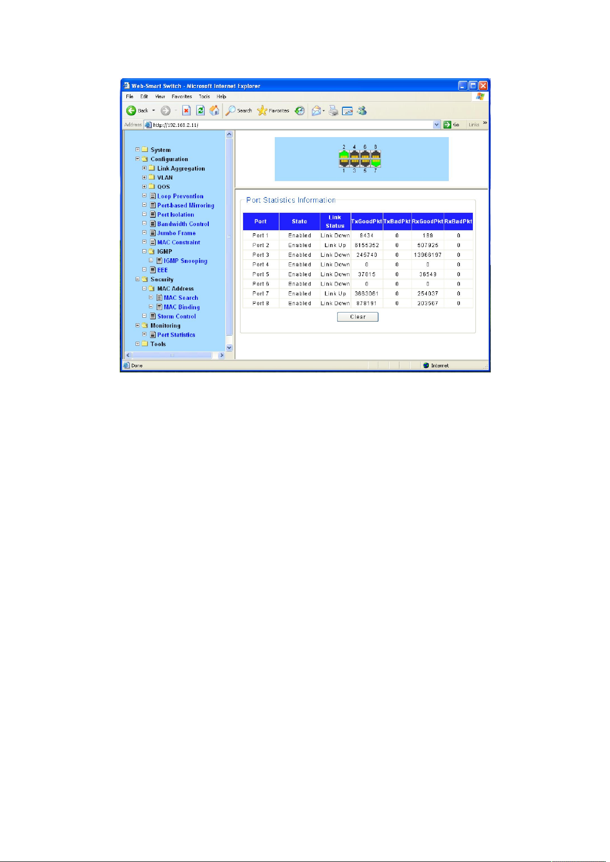
Figure 4-3-21
4.6 Tools
4.6.1 Backup Configuration
On this page you can download the current configuration and save it as a file to your computer
for your future configuration restore.
On this page you can upload a backup configuration file to restore your switch to this previous
configuration.
Choose the menu Tools→ Backup Configuration to load the following page.
37
Page 38
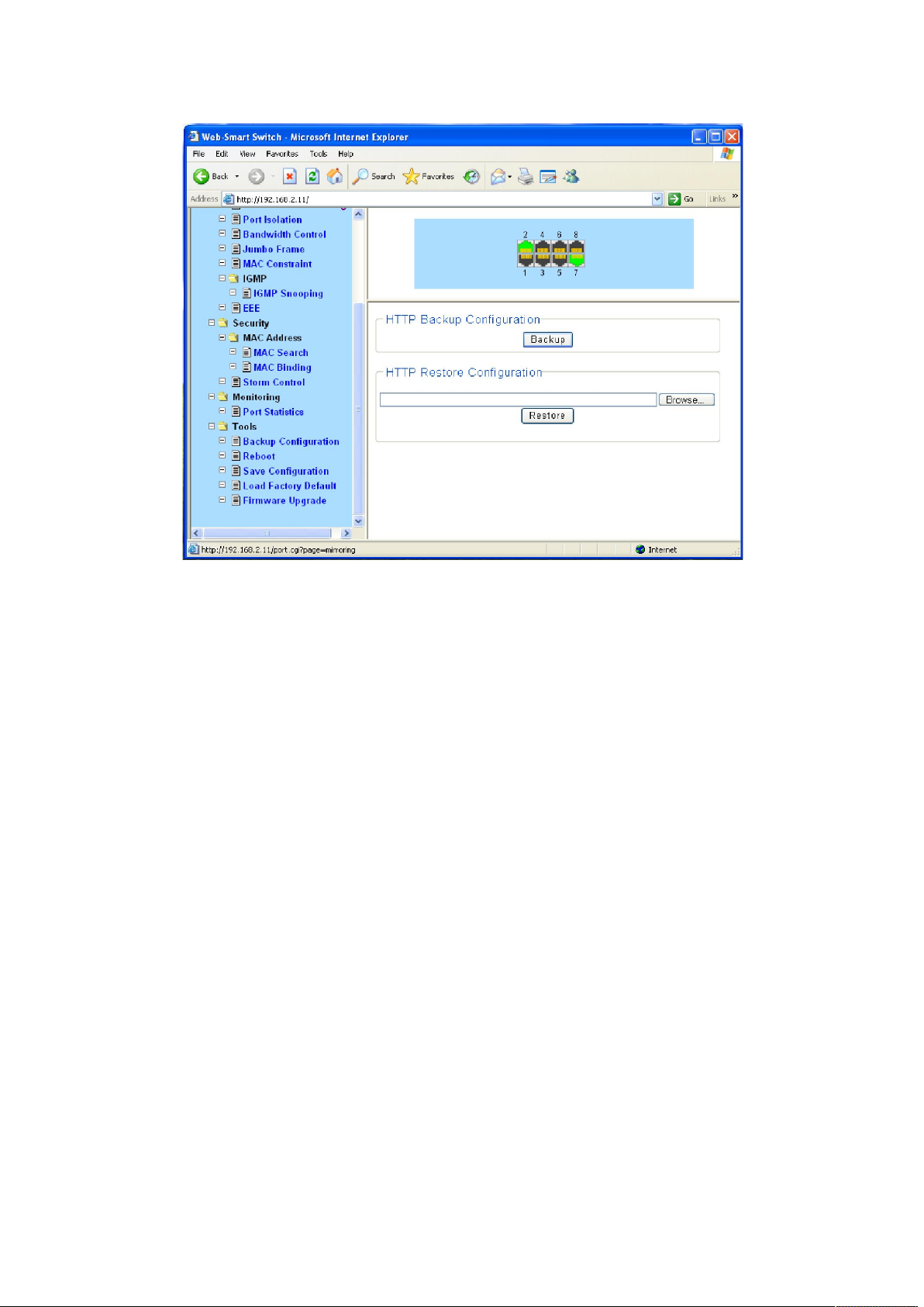
Figure 4-3-22
Click the Backup button to save the current configuration as a file to your computer. You are
suggested to take this measure before upgrading.
Click the Restore button to restore the backup configuration file. It will take effect after the
switch automatically reboots.
4.6.2 Reboot
On this page you can reboot the switch and return to the login page. Please save the current
configuration before rebooting to avoid losing the configuration unsaved
Choose the menu Tools→ Reboot to load the following page.
38
Page 39
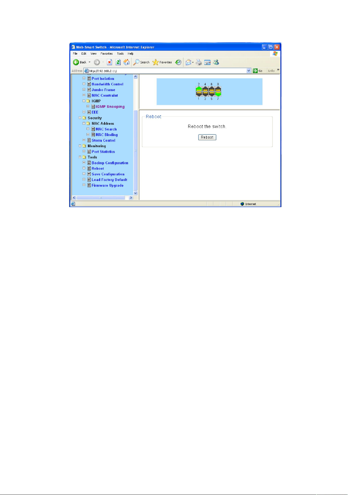
Figure 4-3-23
4.6.3 Save Configuration
When the switch is saved configuration, the settings will be immediately applied to the switching
software in RAM, and will immediately take effect.
Choose the menu Tools→ Save Configuration to load the following page.
39
Page 40

Figure 4-3-24
Click the save button, which can make parameters to be saved, your configuration will still work
after restart.
4.6.4 Load Factory Default
On this page you can reset the switch to the default. All the settings will be cleared after the
switch is reset.
Choose the menu Tools→ Load Factory Default to load the following page.
40
Page 41

Figure 4-3-25
After the system is reset, the switch will be reset to the default and all the settings will be
cleared.
4.6.5 Load Factory Default
The switch system can be upgraded via the Web management page. To upgrade the system is to
get more functions and better performance. Go to http://http://www.netis-systems.com/ to
download the updated firmware.
Choose the menu Tools→ Firmware Upgrade to load the following page.
41
Page 42

Figure 4-3-26
Don’t interrupt the upgrade, to avoid damage, please don't turn off the device while upgrading.
42
 Loading...