

Page 1

Author : NetisIT R&D
2013-12-16
NETIS Information & Technology R&D Center
N9000 Tablet PC
User’s Manual v1.1 (Eng)
Page 2

Doc Name N9000 User’s Manual (Eng) Part R&D center
Doc Ver. v1.1 Date 2013.12.16 Author
1
Document History
Date Ver. History Author
2013.12.13 1.0 First Release
2013.12.16 1.1 Update contents
Page 3

Doc Name N9000 User’s Manual (Eng) Part R&D center
Doc Ver. v1.1 Date 2013.12.16 Author
2
Disclaimer
The information in this document is subject to change without notice. The manufacturer makes no
representations or warranties regarding the contents of this manual and specifically disclaims any
implied warranties of merchantability or fitness for any particular purpose. Furthermore, the
manufacturer reserves the right to revise this publication or make changes in the specifications of the
product described within it at any time without notice and without obligation to notify any person of
such revision.
Trademarks
NetisIT and N9000, Microsoft, Windows and other trademarks and product names used in this manual
are the properties of their respective owners and are acknowledged.
Copyright
This publication, including all photographs, illustrations and software, is protected under international
copyright laws, with all rights reserved. Neither this manual, nor any of the material contained herein,
may be reproduced without the express written consent of the manufacturer.
Page 4

Doc Name N9000 User’s Manual (Eng) Part R&D center
Doc Ver. v1.1 Date 2013.12.16 Author
3
Head Quarters
Netis Information & Technology Co., Ltd.
Address : Anyang
K
-Center 1002~1003, 1591-9, Gwanyang-dong, Dongan-gu, Anyang-si, Gyeonggido, Korea
phone : 82-31-387-1988
Fax : 82-31-387-1989
Email: netisit@netisit.com
Web: www.netisit.com
Page 5

Doc Name N9000 User’s Manual (Eng) Part R&D center
Doc Ver. v1.1 Date 2013.12.16 Author
4
Limited Warranty
NetisIT warrants its products to be free from defects in materials and workmanship and to conform to
NetisIT published specifications applicable to the products purchased at the time of shipment. This
warranty does not cover any product which is (i) improperly installed or used; (ii) damaged by accident
or negligence, including failure to follow the proper maintenance, service, and cleaning schedule; or (iii)
damaged as a result of (A) modification or alteration by the purchaser or other party, (B) excessive
voltage or current supplied to or drawn from the interface connections, (C) static electricity or electrostatic discharge, (D) operation under conditions beyond the specified operating parameters, or (E)
repair or service of the product by anyone other than NetisIT or its authorized representatives.
This warranty shall extend from the time of shipment for the duration published by SmarTerminla for
the product at the time of purchase ("Warranty Period"). Any defective product must be returned (at
purchaser’s expense) during the Warranty Period to NetisIT’s factory or authorized service center for
inspection. No product will be accepted by NetisIT without a Return Materials Authorization, which may
be obtained by contacting NetisIT. In the event that the product is returned to NetisIT or its authorized
service center within the Warranty Period and NetisIT determines to its satisfaction that the product is
defective due to defects in materials or workmanship, NetisIT at its sole option, will either repair or
replace the product without charge, except for return shipping to NetisIT.
EXCEPT AS MAY BE OTHERWISE PROVIDED BY APPLICABLE LAW, THE FOREGOING WARRANTY IS IN
LIEU OF ALL OTHER COVENANTS OR WARRANTIES, EITHER EXPRESSED OR IMPLIED, ORAL OR
WRITTEN, INCLUDING, WITHOUT LIMITATION, ANY IMPLIED WARRANTIES OF MERCHANTABILITY OR
FITNESS FOR A PARTICULAR PURPOSE.
Page 6

Doc Name N9000 User’s Manual (Eng) Part R&D center
Doc Ver. v1.1 Date 2013.12.16 Author
5
Important safety information
Before you use the N9000Tablet PC(referred to as the N9000), read these safety instructions and the
operation instructions in this handbook.
Failure to observe all these instructions voids the Limited Warranty and may lead to suspension or
denial of services to the offender, or legal action, or both.
Follow any special regulations governing the use of the N9000 and, if radio enabled, always switch it
off in areas where radio devices are forbidden or when the radio device can cause interference or
danger.
Always follow any safety laws and regulations pertaining to the use of cell phones and two-way radios,
because these laws and regulations typically apply to the use of the wireless-enabled N9000.
Observe all restrictions on the use of radio equipment in fuel depots (fuel storage and distribution
areas), chemical plants, and wherever blasting operations are in progress or in any area in which
restrictions on radio transmissions are imposed.
Switch off the N9000 when in an aircraft. The N9000 is not FAA-approved for use on aircraft. The effect
of the use of the N9000 in aircraft is unknown. Using the N9000 in an aircraft may affect aircraft
instrumentation, communication, and performance; may disrupt the network; and may be illegal.
Operating the wireless-enabled N9000 may interfere with the functioning of inadequately protected
medical devices such as pacemakers.
Consult a physician or the manufacturer of the medical device if you have any questions.
Radio signals from your N9000 will not affect the operation of most modern equipment, but certain
electronic equipment, including automotive systems, may not be shielded against radio signals from
your N9000.
Check with the manufacturer of your motor vehicle or the manufacturer’s representative to determine
whether using the N9000 will present any safety issues.
Avoid using the N9000 in any environment that requires your full attention, such as when driving a
vehicle. If you need to use your N9000 while driving, have a passenger use it for you or find a safe
location to halt your vehicle.
Page 7

Doc Name N9000 User’s Manual (Eng) Part R&D center
Doc Ver. v1.1 Date 2013.12.16 Author
6
WARNING
Use only battery types specified in this handbook. Using any other type of battery can be dangerous
and can disable the N9000.
Do not use any dock or any other accessory or attachment that is not manufactured or supplied by
NetisIT or an authorized NetisIT accessories supplier.
Use of any accessory or attachment that is not supplied or approved for use with the N9000 by NetisIT
is not permitted because it may cause hazards.
Operate the N9000 only from the type of power source indicated on the marking label Route power
supply cords so that they are not likely to be walked on or pinched by items placed upon or against
them.
Pay particular attention to cords at plugs and convenience receptacles, and at the point where cords
exit from the N9000 or its dock. Do not overload wall outlets, extension cords, or integral convenience
receptacles because this can cause fire or electric shock.
Unplug the N9000 and refer the N9000 and dock for service to qualified service personnel if any of the
following conditions occur:
■The power supply cord or plug is damaged.
■ The N9000 or dock does not operate normally when you follow the instructions in this book.
■ The N9000 or dock exhibits a distinct change in performance.
Adjust only controls for which there are instructions in this book.
An improper adjustment of other controls can result in damage and may require extensive work by a
qualified technician to restore the N9000 or dock to normal operation.
Page 8

Doc Name N9000 User’s Manual (Eng) Part R&D center
Doc Ver. v1.1 Date 2013.12.16 Author
7
CAUTION
Avoid prolonged physical contact with the exposed metal surfaces on the front and back of the N9000.
Operation while the N9000 may not feel hot to the touch, if you maintain physical contact with the
N9000 for a long time (for example, if you rest the N9000 on your lap for a long time), your skin may
suffer low-heat injury. In addition, be careful when you remove a PC card that has been used for a long
time, because the card may be hot.
Page 9

Doc Name N9000 User’s Manual (Eng) Part R&D center
Doc Ver. v1.1 Date 2013.12.16 Author
8
Contents
WELCOME .............................................................................................................................. 11
ABOUT THIS MANUAL ....................................................................................................... 12
ORDERING INFORMATION ............................................................................................... 12
SYSTEM SPECIFICATIONS ............................................................................................... 13
1 GETTING STARTED ....................................................................................................... 14
1.1 Getting started ......................................................................................................................................... 15
Make sure you have everything .................................................................................................................................. 15
1.2 Getting to know your N9000 ............................................................................................................... 16
1.2.1 Front view .................................................................................................................................................................... 16
1.2.2 Rear view ..................................................................................................................................................................... 20
1.2.3 Top view ........................................................................................................................................................................ 21
1.2.4 Bottom view ............................................................................................................................................................... 22
1.2.5 Right view .................................................................................................................................................................... 25
1.2.6 Left view ....................................................................................................................................................................... 27
2 QUICK START ................................................................................................................... 28
2.1 Turning on the N9000 for the First Time ......................................................................................... 29
2.2 Turning Off the N9000 ........................................................................................................................... 29
3 USING A N9000 UTILITY .............................................................................................. 30
Page 10

Doc Name N9000 User’s Manual (Eng) Part R&D center
Doc Ver. v1.1 Date 2013.12.16 Author
9
Device Control .................................................................................................................................................. 32
WIFI Enable/Disable ................................................................................................................................................................ 32
Bluetooth Enable/Disable ..................................................................................................................................................... 33
Mobile Enable/Disable ........................................................................................................................................................... 34
GPS Enable/Disable ................................................................................................................................................................. 37
CAM-F Enable/Disable ........................................................................................................................................................... 38
CAM-R Enable/Disable ........................................................................................................................................................... 39
Application Launch ......................................................................................................................................... 41
External Display ......................................................................................................................................................................... 41
Display Rotate ............................................................................................................................................................................ 42
Internet Explorer ....................................................................................................................................................................... 43
Wi-Fi Setup ................................................................................................................................................................................. 44
Bluetooth Setup ........................................................................................................................................................................ 44
Seeking Bar (Brightness and sound control) ......................................................................................... 45
Brightness control ................................................................................................................................................................ 45
Sound Volume Control ...................................................................................................................................................... 45
For extra information, and help ................................................................................................................. 45
Fn’ button on N9000 .......................................................................................................................................................... 45
Configure Touchscreen In Windows Vista / 7 ......................................................................................... 46
4 POWER MANAGEMENT .................................................................................................. 47
4.1 Checking the Battery Level .................................................................................................................. 48
4.2 Monitoring Battery Power ..................................................................................................................... 48
5 CALIBRATION ................................................................................................................... 53
PenMount Control Panel ................................................................................................................................ 54
6 CRADLE REFERENCE GUIDE ............................................................................................ 59
Page 11

Doc Name N9000 User’s Manual (Eng) Part R&D center
Doc Ver. v1.1 Date 2013.12.16 Author
10
6-1. Desktop cradle ....................................................................................................................................... 60
6-2. Vehicle cradle ............................................................................................................................................ 64
7 TROUBLE SHOOTING GUIDE ....................................................................................... 68
Troubleshooting for Wireless ....................................................................................................................... 69
Troubleshooting for battery ......................................................................................................................... 71
Troubleshooting for Bluetooth problem.................................................................................................... 72
Troubleshooting for Display Problem ........................................................................................................ 73
Troubleshooting for Date/Time Problems ................................................................................................ 74
Troubleshooting for Sound Problems ........................................................................................................ 75
8 FIRMWARE UPDATE ........................................................................................................ 76
9 APPENDIX .......................................................................................................................... 80
FCC Compliance Statement ......................................................................................................................... 81
※ This product is used only for WIFI, Bluetooth.
Page 12

Doc Name N9000 User’s Manual (Eng) Part R&D center
Doc Ver. v1.1 Date 2013.12.16 Author
11
Welcome
Congratulations on selecting the N9000, supported by Microsoft Windows®, XP, Vista, 7.
This unique N9000 offers a special combination of features that make it an ideal partner for a wide
range of applications.
Our products can fulfill most of outdoor N9000 applications. Great thermal conduction and solid
mechanical design make our products great reliability in harsh, highly-shock and vibration environment.
Page 13
Doc Name N9000 User’s Manual (Eng) Part R&D center
Doc Ver. v1.1 Date 2013.12.16 Author
12
About this Manual
This User’s Manual is intended for experienced users and integrators with hardware knowledge of
personal computers. If you are not sure about any description in this User’s Manual, please consult
your vendor before further handling.
The following chapters contained in this manual are:
Chapter 1: Getting Started - Basic functions of the N9000.
Chapter 2: Starting N9000 Utility - Using the system management software included with the N9000.
Chapter 3: Maintenance and Troubleshooting - How to maintain, calibrate and replace components;
a troubleshooting FAQ details how to diagnose and correct typical problems.
Ordering Information
Ordering no. Description
N9000
Vehicle cradle
Desktop cradle
Main battery
Sub battery
AC/DC Adapter (AC100-220V Input)
DC/DC Converter(DC12 ~16V input)
Cigar jack adapter
Mobile Antenna
GPS Antenna
Page 14
Doc Name N9000 User’s Manual (Eng) Part R&D center
Doc Ver. v1.1 Date 2013.12.16 Author
13
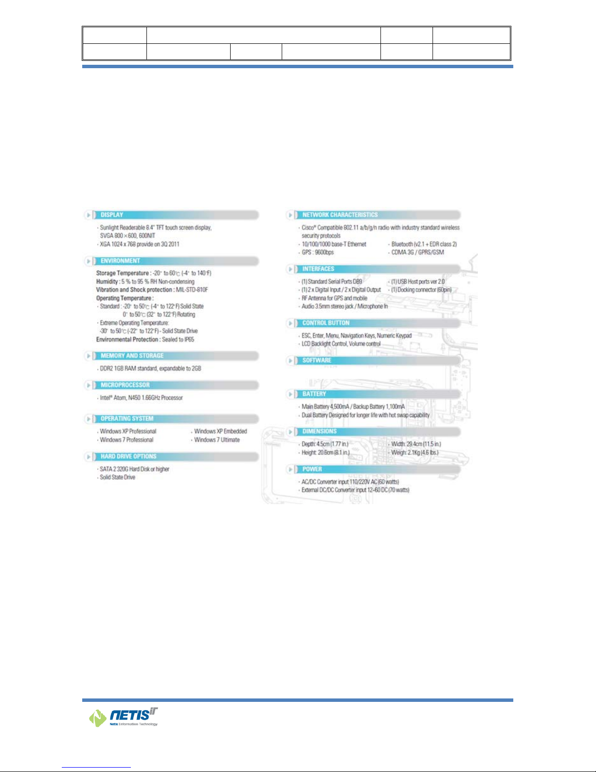
System Specifications
The N9000 meets the following specifications. Unless otherwise noted, allthe specifications listed below
are subject to change without prior notification.
Page 15

Doc Name N9000 User’s Manual (Eng) Part R&D center
Doc Ver. v1.1 Date 2013.12.16 Author
14
1 Getting Started
Chapter 1
Getting Started
Page 16

Doc Name N9000 User’s Manual (Eng) Part R&D center
Doc Ver. v1.1 Date 2013.12.16 Author
15
1.1 Getting started
This chapter gives you an overview of your N9000 and includes a quick-start guide to N9000 keys.
There are three ways in which N9000 can be used or mounted
1. Desktop docking station
2. Vehicle docking station
3. Without any docking station
Make sure you have everything
After opening the package, carefully inspect the contents. If any of the items are missing or
appear
damaged, contact your dealer. The shipping carton should contain the following:
N9000
Stylus Pen
AC/DC Adaptor
Lithium -Ion Rechargeable Battery Pack
Power cord
Quick Reference guide
Optional accessories
Docking station (Vehicle, desktop)
Cigar Jack adapter
DC/DC power supply
External LAN cable
Page 17

Doc Name N9000 User’s Manual (Eng) Part R&D center
Doc Ver. v1.1 Date 2013.12.16 Author
16
1.2 Getting to know your N9000
1.2.1 Front view
Key pad
Anti-Shock Cushions
MIC Navigation Key
Power & Reset button
HDD & Wi-Fi
LED indicators
Battery LED indicator
8.4” TFT LCD
1.3Mega Pixel
Camera
Speaker
Page 18

Doc Name N9000 User’s Manual (Eng) Part R&D center
Doc Ver. v1.1 Date 2013.12.16 Author
17
LED Indicator
Icon Light Description
Red Power is on
Flashing Red System is in standby mode
Blue WLAN is enabled
No light WLAN is not powered
Green N9000 is reading from or writing to the built in SSD or HDD
No light HDD is idle
Red Battery is charging
Green Battery is fully charged
Power & Reset Button
When clicking power button (when you turn on), the button stays with red light.
Reset Button works simply as reboot, and this doesn’t remove programs or anything just as general
computers.
ESC Button
Works likewise as computer.
Menu Button
This button makes N9000 Utility to pop up to the display screen if it was minimized on the Tray.
Page 19

Doc Name N9000 User’s Manual (Eng) Part R&D center
Doc Ver. v1.1 Date 2013.12.16 Author
18
Numeric Key Button
1) When ‘Fn’ is enabled: simply works as number button
2) When ‘Fn’ is disabled: use as Key Map definition function. (to help memorize functions, the drawings
under the numbers are actually related each function. For example, #5 button shows radar wave,
indicating WiFi On/Off)
[Key Map]
KEYS Function
Fn + 0 F4
Fn + 1 F3
Fn + 2 Turn on/off CDMA and 3G/GPRS
Fn + 3 Key Pad Lock
Fn + 4 F2 (BIOS Setup Key)
Fn + 5 Turn on/off WLAN
Fn + 6 Touch Calibration
Fn + 7 F1 (BIOS Multi-Boot)
Fn + 8 Display Rotate
Fn + 9 On Screen Keyboard
Page 20

Doc Name N9000 User’s Manual (Eng) Part R&D center
Doc Ver. v1.1 Date 2013.12.16 Author
19
Key Pad Lock / Unlock
The main purpose of placing a keypad lock[Fn+3] to a N9000 is to prevent accidental key input.
You can unlock the keypad via N9000 Utility.
Navigation Key (arrow keys)
1) When ‘Fn’ is disabled: serves simply as arrow keys
2) When ‘Fn’ is enabled: works as Seeking Bar in N9000 Utility
- Left / Right: Brightness control
- Up / Down: Sound Device volume
Page 21

Doc Name N9000 User’s Manual (Eng) Part R&D center
Doc Ver. v1.1 Date 2013.12.16 Author
20
1.2.2 Rear view
Camera
The 3MP Color Camera is located on the back panel of the computer. The camera can be used for
picture capture as well as streaming video.
Hot-Swappable Battery
Refresh your power supply without shutting down. With a 30 minute swap time, the hot-swappable
battery pack can easily be replaced in the field
3Mega Pixel Camera
Hot Swappable Battery
Page 22

Doc Name N9000 User’s Manual (Eng) Part R&D center
Doc Ver. v1.1 Date 2013.12.16 Author
21
1.2.3 Top view
GPS Internal Antenna
An internal GPS active antenna is suitable for mobile applications
Mobile Antenna
Mobile Antenna for GSM GPRS or CDMA
GPS Antenna
Mobile Antenna
Page 23

Doc Name N9000 User’s Manual (Eng) Part R&D center
Doc Ver. v1.1 Date 2013.12.16 Author
22
1.2.4 Bottom view
VGA
D-Sub 15 pin VGA connector for display output
Docking connector
When seated in a N9000 peripheral, the Device is powered, the batteries charged, and communication
occurs via this connector.
Docking Connector
VGA Port
DIO Connector (Option)
RS-232 Port (Default)
Page 24

Doc Name N9000 User’s Manual (Eng) Part R&D center
Doc Ver. v1.1 Date 2013.12.16 Author
23
Connector Layout
Colum
n 1
Colum
n 2
Colum
n 3
Colum
n 4
Colum
n 5
Colum
n 6
Colum
n 7
Colum
n 8
Colum
n 9
Colum
n 10
Row 0 VCC VCC
LinkLe
d+
+5V
(USB)
CD RI
BI_DA
+
BI_DA- GND GND
Row 1 VCC VCC
LinkLe
d-
DM RXD CTS
BI_DB
+
BI_DB- GND GND
Row 2 VCC VCC
ActLed
+
DP TXD RTS
BI_DC
+
BI_DC- GND GND
Row 3 N3 N2
ActLed
-
N1 DTR DSR
BI_DD
+
BI_DD- GND GND
DIO Connector Pin Map
Connector DIO (DB15 Male)
Pin map
1 2 3 4 5 6 7
DI0+ DI0- DI1+ DI1- GND DI2+ DI2-
8 9 10 11 12 13 14 15
DI3+ DI3- GND DO0+ DO0- DO1+ DO1- GND
Page 25

Doc Name N9000 User’s Manual (Eng) Part R&D center
Doc Ver. v1.1 Date 2013.12.16 Author
24
DIO Functional Test
Connect to DIO Test board to the DIO port of N9000 or own
Run N9000DIDO on the desktop
You can check and test for DI and DO on the N9000 DIDO utility.
Page 26

Doc Na
Doc V
e
1.2.5
DC-in
j
Power su
p
to the PC,
LAN R
J
The eight
-
connectio
n
LAN RJ45
me N9
r.
Right vie
j
ack
plied throu
g
always use
-45 jack
pin RJ-45 L
A
to a local
n
Connector
w
D
000 User’s
M
v1.1
w
h this jack
s
the supplie
d
N port sup
p
etwork.
ith LED Ind
C-IN
anual (Eng
Date
upplies po
w
power ada
orts a stan
d
icators.
RJ45
)
20
1
er to the P
C
pter.
ard Ethern
e
3.12.16
. To preven
t cable for
RS-
2
Part
Autho
r
t damage
32
R&D center
25
Page 27

Doc Na
Doc V
e
9-pin
S
Use this j
a
Com1 RS
2
me N9
r.
erial co
m
ck to conn
e
32(DB9 ma
000 User’s
M
v1.1
munica
t
ct to your p
le connecto
r
anual (Eng
Date
ions jac
k
rinter for h
a
)
)
20
1
rd-copy pri
n
3.12.16
ting.
Part
Autho
r
R&D center
26
Page 28

Doc Na
Doc V
e
1.2.6
USB p
o
The Univ
e
and other
Headp
Connect a
Micro
p
Connect a
me N9
r.
Left vie
w
rts
rsal Serial
B
devices to
a
hone jac
k
stereo hea
d
hone-in
j
microphon
e
000 User’s
M
v1.1
us (USB) i
s
PC. USB d
e
set or exte
r
ack
in this jac
k
USB Port
anual (Eng
Date
the latest
vices can b
e
nal speake
r
to record a
)
20
1
standard fo
r
e
chained t
o
s to this jac
udio.
Headphon
e
3.12.16
attaching
m
gether on a
k to listen t
o
Jack
Part
Autho
r
onitors, in
single cabl
e
multimedi
a
Microph
o
R&D
put devices
,
.
.
ne-in Jack
center
27
scanners,
Page 29

Doc Name N9000 User’s Manual (Eng) Part R&D center
Doc Ver. v1.1 Date 2013.12.16 Author
28
2 Quick Start
Chapter 2
Quick Start
Page 30

Doc Name N9000 User’s Manual (Eng) Part R&D center
Doc Ver. v1.1 Date 2013.12.16 Author
29
2.1 Turning on the N9000 for the First Time
Use the following instructions the first time an N9000 is turned on. After which you will only
need to press the power button on the keypad as N9000 should be fully charged andready to go.
To turn on the N9000
1. Connect the AC adapter power cord to the AC adapter.
2. Connect the AC adapter power cord to an AC outlet.
3. Connect the AC adapter to the DC power port on the left side of your N9000.
4. Press the power button 3sec. or more on the keypad to turn on the power.
2.2 Turning Off the N9000
Turning off the N9000 properly is important to maintaining your rugged N9000.
To turn off the N9000
Select Start >Shut down.
Caution: Shutting off the N9000 improperly may result in loss of data.
Page 31

Doc Name N9000 User’s Manual (Eng) Part R&D center
Doc Ver. v1.1 Date 2013.12.16 Author
30
3 Using a N9000 utility
Chapter 3
Using a N9000 utility
Page 32

Doc Name N9000 User’s Manual (Eng) Part R&D center
Doc Ver. v1.1 Date 2013.12.16 Author
31
This Chapter will give you how to use menu function including basic hardware function adjustment and
theN9000 Utility software that is very easy & helpful for operating the computer.
As N9000 start, N9000 Utility will then automatically run (start) through forwarding process.
As illustrated below, on the bottom right side of Tray Icon, you can see the N9000 Utility icon
minimized indicated as a red square.
To show N9000 Utility, simply double click on the Tray Icon if it’s minimized.
If ‘Fn’ button is enabled (pressed down), then you will see the tray icon like below, shown as blue color
If ‘Fn’ button is not active (or not pressed down, not touched), then gray color as below.
Page 33

Doc Name N9000 User’s Manual (Eng) Part R&D center
Doc Ver. v1.1 Date 2013.12.16 Author
32
Device Control
You can also utilize each device respectively by using N9000 Utility to toggle it as ‘Enable / Disable’
WIFI Enable/Disable
When clicking Wifi button from the N9000 Utility, you can enable / disable of N9000.
When disabling the Device, you can’t access (connect) to Wi-Fi.
1) When Wi-Fi is enabled: You can check Wireless LAN Device from the Device Manager as illustrated
below.
Page 34

Doc Name N9000 User’s Manual (Eng) Part R&D center
Doc Ver. v1.1 Date 2013.12.16 Author
33
2) When WiFi is disabled: You won’t be able to see nor check Wireless LAN Device from the Device
Manager.
Even if you go to Network -> Property -> adapter, you still won’t be able to see nor check it.
Bluetooth Enable/Disable
When clicking Bluetooth button at the N9000 Utility, you can also enable / disable Bluetooth Device of
N9000.
When disabling Device, it’s impossible to access to Bluetooth.
1) When Bluetooth is enabled: You can check Bluetooth Device from Device Manager.
Page 35

Doc Name N9000 User’s Manual (Eng) Part R&D center
Doc Ver. v1.1 Date 2013.12.16 Author
34
2) When WiFi is disabled: WiFi Device is disabled as well. From the Device Manager, you will see
Bluetooth Device has disappeared as shown below.
Mobile Enable/Disable
When clicking ‘Mobile’ button from the N9000 Utility, you can enable / disable of CDMA Device or
GPRS/GSM of N9000.
When disabling Mobile Device, it’s impossible to connect or access through 2G.
For CDMA Model
1) For CDMA model, when ‘Mobile’ button is enabled:
CDMA 2G
As shown below, U600 EVDO Modem (for phone connection), U600 EVDO Network Adapter (for WWAN),
3 serial ports (for GPS data base, serial connection etc.), when they are shown in the Device Manager
as red squares, it means CDMA model is enabled (working normally).
(For additional info, U600 CM Port’s default value is COM5, and the administer (user) of computer can
change it.)
Page 36

Doc Name N9000 User’s Manual (Eng) Part R&D center
Doc Ver. v1.1 Date 2013.12.16 Author
35
2) When disabling ‘Mobile’ button of GPRS/GSM model:
If you see ‘GC864 GPRS USB Modem’, ‘GPRS GC864 USB to UART Bridge’ at the Device Manager, it
means GPRS is disabled. It’s illustrated as below in red squares.
Page 37

Doc Name N9000 User’s Manual (Eng) Part R&D center
Doc Ver. v1.1 Date 2013.12.16 Author
36
For GPRS/GSM Model( GoBi3000 for Sierra MC8355)
1) For GPRS/GSM model, when ‘Mobile’ button is enabled:
Check if all the 3G related devices are detected from the device manager. Refer the image below.
Page 38

Doc Name N9000 User’s Manual (Eng) Part R&D center
Doc Ver. v1.1 Date 2013.12.16 Author
37
▷ Sierra Wireless WWAN Modem
▷ Sierra Wireless Mobile Broadband Network Adapter
▷ Sierra Wireless DM Port
▷ Sierra Wireless NMEA Port
GPS Enable/Disable
When clicking ‘GPS’ button in N9000 Utility, you can also enable / disable the function of GPS of N9000.
When disabling the Device, access (or connect) to GPS becomes impossible.
*It is important to note that when CDMA is disabled, GPS will also be disabled simultaneously, it’s
normally done by mechanism of the computer.
Page 39

Doc Name N9000 User’s Manual (Eng) Part R&D center
Doc Ver. v1.1 Date 2013.12.16 Author
38
CAM-F Enable/Disable
When clicking ‘CAM-F’ button from N9000 Utility, you can enable / disable the Device of frontal cam of
N9000.
When disabling the Device, you can’t use the cam at all, the ‘USB Video Device’ won’t be shown as
illustrated as below to prove.
In order to see if CAM is working normally, simply go to “N9000 Camera” (Use the N9000 Camera
Page 40

Doc Name N9000 User’s Manual (Eng) Part R&D center
Doc Ver. v1.1 Date 2013.12.16 Author
39
Shortcut in the desktop background)
caution: When updating USB Video Device Driver, the frontal camera might not work
properly.
CAM-R Enable/Disable
When clicking ‘CAM-R’ button from N9000 Utility, you can enable / disable the Device of the rear side
of the cam.
Once the device becomes disabled, the rear side cam will not work.
Page 41

Doc Name N9000 User’s Manual (Eng) Part R&D center
Doc Ver. v1.1 Date 2013.12.16 Author
40
In order to see if rear cam is working, go to “N9000 Camera” application. (“N9000 Camera” shortcut in
the desktop background)
Page 42

Doc Name N9000 User’s Manual (Eng) Part R&D center
Doc Ver. v1.1 Date 2013.12.16 Author
41
Application Launch
By using the N9000 Utility, you can launch the application related to each function.
External Display
When clicking ‘External Display’ button from N9000 Utility, it will information regarding Display, and
using this application, you can change the display settings such as video settings as shown below.
Page 43

Doc Name N9000 User’s Manual (Eng) Part R&D center
Doc Ver. v1.1 Date 2013.12.16 Author
42
Display Rotate
When clicking ‘Display Rotate’ button, you can also turn the N9000 screen with 90 degree angle anticlock wise.
For example, it changes 800x600 to 600x800..
If you click Display Rotate button again, it goes back to 800x600.
Page 44

Doc Name N9000 User’s Manual (Eng) Part R&D center
Doc Ver. v1.1 Date 2013.12.16 Author
43
Internet Explorer
Page 45

Doc Name N9000 User’s Manual (Eng) Part R&D center
Doc Ver. v1.1 Date 2013.12.16 Author
44
Wi-Fi Setup
When you click WiFi Setup from N9000 Utility, ‘Wireless LAN Driver Configuration Program’ which is
installed in N9000 will run.
Bluetooth Setup
When you click Bluetooth Setup button, ‘Bluetooth Driver Setup Program’ will run.
* You need to install Bluetooth program (which works similar to BlueSoleil), because the current N9000
doesn’t have it installed. *Bluetooth module is already installed in the N9000.
Page 46

Doc Name N9000 User’s Manual (Eng) Part R&D center
Doc Ver. v1.1 Date 2013.12.16 Author
45
Seeking Bar (Brightness and sound control)
Brightness control
Simply use this flower looking button to move left and right. It’s located at the bottom of N9000 Utility
when it pops up.
Sound Volume Control
It Works same as brightness control.
For extra information, and help
Fn’ button on N9000
When pressed:
When Un-Pressed:
Page 47

Doc Name N9000 User’s Manual (Eng) Part R&D center
Doc Ver. v1.1 Date 2013.12.16 Author
46
Configure Touchscreen In Windows Vista / 7
With PenMount Windows Universal V2.2.0.283 and later versions, since the touchscreen is
automatically installed as a digitizer device in Windows Vista/7, the functions which are built within
Windows Vista / 7 such as rotation, multi-monitors, flicks, and context menu function (which launches
a context menu by user’s long-pressing on touchscreen rather than clicking the right-mouse button or
pressing the application key on the keyboard) will be supported.
To configure touchscreen in Windows Vista / 7:
Double-click on the PenMount Control Panel icon on the Desktop.
PenMount Control Panel opens. You will be able to see the icon of PenMount 6000 USB under Device
tab. In Device tab, you can see the devices detected on your system. Select a device and press the
Configure button to configure it.
Page 48

Doc Name N9000 User’s Manual (Eng) Part R&D center
Doc Ver. v1.1 Date 2013.12.16 Author
47
4 Power management
Chapter 4
Power management
Page 49

Doc Name N9000 User’s Manual (Eng) Part R&D center
Doc Ver. v1.1 Date 2013.12.16 Author
48
4.1 Checking the Battery Level
You can check the remaining battery power in the Windows® battery status indicator located at the
lower right-hand corner of the task tray. The Battery status icon only appears in the task tray while the
unit is running on the battery power.
Battery Power Indicator
4.2 Monitoring Battery Power
There are four ways to monitor how much power battery has left.
1. Click Start / Settings / Control Panel / Power Options then click Power Meter.
If you do not see the battery icon, enable it in Start / Settings /Control Panel / Power Options.
Choose the Advanced tab and click“Always show icon on the taskbar.”
2. Moving the cursor to the battery icon on the task bar is the simplest way to check on battery
power status.
Page 50

Doc Name N9000 User’s Manual (Eng) Part R&D center
Doc Ver. v1.1 Date 2013.12.16 Author
49
3. You can check for battery status by NetisIT Logo LED Color.
Green LED means that fully charged
Red LED means that battery charging.
Red LED flicker alternately means that low battery less than 10%
Page 51

Doc Name N9000 User’s Manual (Eng) Part R&D center
Doc Ver. v1.1 Date 2013.12.16 Author
50
4. You can check battery status via N9000 Utility.
Page 52

Doc Name N9000 User’s Manual (Eng) Part R&D center
Doc Ver. v1.1 Date 2013.12.16 Author
51
Low Battery Alarms
How your N9000 responds to a low battery condition is set under
Start / Settings / Control Panel / Power Options / Alarms.
Two different power alarms can be enabled or disabled: the Low
Battery Alarm, and the Critical Battery Alarm.
Warning: When battery power is low, the battery
indicator will flash red, and the alarm will
display a warning on your screen. Take immediate
action, such as saving files or connecting to the AC adapter, or data may be lost.
Battery Charging
When you use the AC adapter to connect your N9000 to a power outlet, the internal battery will
automatically begin to recharge. While the battery is charging, the Battery Charge icon on the
Indicator panel will be active after 6~12 seconds. When the battery is fully charged, the Battery
Charge icon will turn off.
If your N9000 is turned off, a fully discharged battery will take about 3 hours to recharge. If your
N9000 is turned on and is not in suspend mode, it will take about 4~5 hours to recharge the
battery.
Refer to the following table:
Charging
System on
Under Screen Saver Mode)
4~5 hours
System off ( suspend to RAM) ~4 hours
Note: A fully charged Li-Ion battery can run the N9000 for approximately 6.0 hours.
When to Replace the Battery
Over time, the battery's capacity gradually decreases. We recommend that you replace your
battery when you notice that it begins to store significantly less charge.
Page 53

Doc Name N9000 User’s Manual (Eng) Part R&D center
Doc Ver. v1.1 Date 2013.12.16 Author
52
Changing the Battery
Change the main battery pack as follows:
1. Turn off the N9000.
2. To replace the Battery remove the screw and the Battery Bay Cover.
3. Make sure the replacement battery is properly orientated. Then insert the battery into the
battery compartment.
Power-Saving Tips
The following are some Power-Saving Tips suggestions to maximize the battery’s operating time.
Do not disable Power Management.
Decrease the LCD brightness to the lowest comfortable level.
Shorten the length of time before Windows turn off the display.
USB devices use power just by being connected. If you use a USB mouse, you can save
powerbydisconnecting the mouse and using the optional touch screen pen.
If you use a USB flash drive, unplug it when you are not using it.
If you work with an application that uses a PC card, exit the application when you finish using it.
If you have a PC card installed, remove it when not in use. Some PC cards drain power even
while they are inactive.
Deactivate the Wireless LAN function if you are not using it (see Chapter 2).
Deactivate the Bluetooth wireless feature if you are not using it (see Chapter 2)
Turn off the N9000 PC when you are not using it.
Page 54

Doc Name N9000 User’s Manual (Eng) Part R&D center
Doc Ver. v1.1 Date 2013.12.16 Author
53
5 Calibration
Chapter 5
Calibration
Page 55

Doc Name N9000 User’s Manual (Eng) Part R&D center
Doc Ver. v1.1 Date 2013.12.16 Author
54
PenMount Control Panel
The functions under PenMount Control Panel are:
Device
In this tab, you can find out how many devices are detected on your system.
Select any device by clicking on its icon.
Calibrate
This function offers two ways to calibrate your touchscreen. ‘Standard
Calibration’ adjusts most touchscreens while ‘Advanced Calibration’ adjusts aging touchscreens.
Standard Calibration Click this button and arrows appear pointing to red
Advanced
Calibration
Command
Calibration
squares. Use your finger or stylus to touch the redsquares in
sequence. After the fifth red point
calibration is complete. To skip, press ‘ESC’.
Advanced Calibration uses 9, 16 or 25 points to
effectively calibrate touch panel linearity of aged
touchscreens. Click this button and touch the red
squares in sequence with a stylus. To skip, press
‘ESC’.
Command call calibration function. Usecommand mode call calibration
function, thiscan uses Standard, 4, 9, 16 or 25 points tocalibrate.
E.g. Please run ms-dos prompt or commandprompt.
c:\Program Files\PenMount Universal
Driver\DMCCtrl.exe -calibration 0 (Standard
Calibration)
Page 56

Doc Name N9000 User’s Manual (Eng) Part R&D center
Doc Ver. v1.1 Date 2013.12.16 Author
55
To calibrate your touchscreen:
1. Please select a device then click “Configure”. You can also double click the device too.
2. Click “Standard Calibration” to start standard
Page 57

Doc Name N9000 User’s Manual (Eng) Part R&D center
Doc Ver. v1.1 Date 2013.12.16 Author
56
NOTE: The older the touchscreen gets, the more Advanced Mode calibration points you need for
an accuratecalibration.
Use a stylus for Advanced Calibration forgreater accuracy.
Do the following for Advanced Calibration:
3. Back in Calibrate tab, press “Advanced Calibration” button to start Advanced Calibration.
NOTE: It is recommended that you use a stylus for Advanced Calibration for greater accuracy.
Page 58

Doc Name N9000 User’s Manual (Eng) Part R&D center
Doc Ver. v1.1 Date 2013.12.16 Author
57
Plot Calibration
Data
Turn off EEPROM
Storage
Edge Compensation
This page is the edge compensation settings for the advanced calibration. You can adjust the settings
from 0 to 30 for accommodating the difference of each touch panel.
Check this function to have touch panellinearity comparison
graph appear whenyou finish Advanced Calibration. Theblack
lines reflect the ideal linearityassumed by PenMount’s
applicationprogram while the blue lines show theapproximate
linearity calculated byPenMount’s application program as
theresult of user’s execution of AdvanceCalibration.
This function disables the write-in ofcalibration data inController.
This function is enabled bydefault.
Page 59

Doc Name N9000 User’s Manual (Eng) Part R&D center
Doc Ver. v1.1 Date 2013.12.16 Author
58
About
This panel displays information about the PenMount controller and driver version
Page 60

Doc Name N9000 User’s Manual (Eng) Part R&D center
Doc Ver. v1.1 Date 2013.12.16 Author
59
6 Cradle Reference Guide
Chapter 6
Cradle Reference Guide
Page 61

Doc Name N9000 User’s Manual (Eng) Part R&D center
Doc Ver. v1.1 Date 2013.12.16 Author
60
6-1. Desktop cradle
Overview
The desktop cradle restrains the N9000, re-charges batteries, and enables serial, USB communication
with a PC,scanner, printer or other peripheral device.
Using a wall AC adapter the desktop cradle can also recharge a spare N9000 battery in approximately
4 hours.
The N9000 cradle is not certified for use in Hazardous Locations.
Key Features
- Recharges the 1x Spare battery pack.
- Provides a connection for serial communications between the N9000 and the host computer or
another serial device, such as a Barcode scanner or modem.
- Power supplies are available that meet either 110V -120V or 200- 240V.
Preparing the Desktop cradle for Use
RS-232
Docking Connector
USB Port
LED Indicator
Stylus pen
holder
Power Connector
Ethernet port
Spare battery
Page 62

Doc Name N9000 User’s Manual (Eng) Part R&D center
Doc Ver. v1.1 Date 2013.12.16 Author
61
Note: Keep dirt and foreign objects out of the docking bays.
Do not short circuit any of the charging terminals (pins) in thedocking bays, as this action
could result in injury or property damage.
NetisIT recommends a stable, horizontal surface out of the way of:
inclement weather conditions,
extremely high concentrations of dust or windblown debris,
accidental knocks, bumps or other shocks to the docking bay.
Leave enough space at the dock power connector to ensure the power supply and power cable are
protected fromjostling, tugging or being disconnected by passing objects.
Do not place the Charging dock in a closed area withrestricted airflow.
Dock the N9000
The N9000 is inserted into the docking bay with the keypad facing forward.
Carefully press the N9000 straight down into the docking bay until the multi-pin connector at the base
of the N9000 clicks intoplace with the multi-pin charging connector at the bottom of the docking bay.
TheSmaterminal logopower LED illuminates of front N9000.
Undock the N9000
Remove the N9000 from the Cradle by pulling it straight up and out of the docking bay.
If necessary, brace the cradle with one hand while the other hand removes the N9000.
The Smaterminal logo power LED turns Off on the N9000.
Using the desk top cradle
Note : The power LED on the front of dock is illuminated when the dock is receiving AC power.
Batteries will not charge unless the Power LED is on.
Page 63

Doc Name N9000 User’s Manual (Eng) Part R&D center
Doc Ver. v1.1 Date 2013.12.16 Author
62
Place the N9000 in the cradle with the touch screen facing out.
The dock will begin charging the batteries. The N9000 can begin communicating with the host
(If the dock is cabled to the host)
Status LED
Power : Red when receiving power from an AC/DC adapter.
Battery : The LED illuminates Red when power is received. A spare battery is seated in the battery bay.
Quick Start Installation for Desk Top Cradle
Place the cradle on a stable surface, close to an uninterrupted AC power source, if a connection to AC
power is required.
1. The desktop cradle can be mounted to a flat surface.
NetisIT does not supply the mounting hardware.
2. If required, connect the AC/DC power supply to the cradle.
The LED indicator on the front of the powered cradle will illuminate orange.
3. The Desk Top cradle is ready for use.
See following section titled “Desk Top Cradle” for full instruction.
Cleaning
Do not use paper towels or harsh-chemical-based cleaning fluids since they may result in damage to
the surfaces and/orbattery charging terminals (pins).
Use a clean soft cloth to wipe any dirt, moisture or grease from the N9000, charging contacts (pins) or
the desktop cradle.
Periodically wipe the cradle with a dry lens tissue or other cleaning materials suitable for optical
applications: such aseyeglasses.
Lintparticulates can be removed from the connectors, charging terminals and charging/docking bays
with clean.
Page 64

Doc Name N9000 User’s Manual (Eng) Part R&D center
Doc Ver. v1.1 Date 2013.12.16 Author
63
Safety Guidelines and Cautions
It is recommended that a grounded three (3) prong AC outlet be used to power this device.
The user should insure thatthe AC outlet is grounded before using this device. If you are not
sure that the AC outlet has appropriate ground, we suggestthat a qualified electrician be called
for verification.
Do not pour, spray or spill any liquid into or on the cradle. If liquid does come in contact with
the cradle, immediatelyun-plug the cradle and remove any devices in the docking bays.
For Indoor Use Only.
Before using this cradle, please read all instructions and cautionary notations on the cradle and
on the N9000.
To reduce risk of injury, only use authorized battery products in the N9000.
Other non-approved batteries may cause personalinjury and / or damage to the equipment.
Do not expose the cradle to excessive moisture, temperature extremes or direct sunlight.
Place cradle in a well ventilated area, which is free of foreign materials.
To reduce risk of electric shock, unplug cradle from power source before cleaning.
Dispose of used batteries in accordance with your state or local hazardous material laws.
Dispose of cradle correctly according to local regulations to comply with WEEE regulations.
Do not disassemble, incinerate, modify, or short circuit the multi-dock, any battery, or related
components.
Page 65

Doc Name N9000 User’s Manual (Eng) Part R&D center
Doc Ver. v1.1 Date 2013.12.16 Author
64
6-2. Vehicle cradle
Overview
Vehicle mounted brackets are specifically designed for vehicle mount applications.
The vehicle mounted assembly restrainsthe N9000 and isolates it from shock and vibration.
Overhead, dash and roof support pillar mounting is via a RAM Mount accessory which includes all the
hardwarerequired for vehicle mounting.
In most cases, disconnect any power and peripheral cables from the N9000 before it is secured in the
vehicle mounted assembly.
Never put the N9000 into the vehicle mounted assembly until the assembly is securely fastened to the
vehicle.
Using the Powered Vehicle Mounted Assembly
Before installation begins, verify you have the applicable vehicle mounting bracket assembly
components necessary for yourmount type.
The powered vehicle mounted assembly should be secured to an area in the vehicle where it:
Does not obstruct the driver's vision or safe vehicle operation.
Will be protected from rain or inclement weather.
Will be protected from extremely high concentrations of dust or wind-blown debris.
Can be easily accessed by a user seated in the driver's seat while the vehicle is not in
operation.
Page 66

Doc Name N9000 User’s Manual (Eng) Part R&D center
Doc Ver. v1.1 Date 2013.12.16 Author
65
Key Features
- Provides a connection for serial communications between the N9000 and the host computer or
another serial device, such as a Barcode scanner or modem.
- Wide input power range from 10V to 60V.
Ethernet port
USB Port
RS-232
Power Connecter
Docking Connector
Power Switch
Clamp lever
Key lock
Cable Clamp
VESA Mount (75X75)
Page 67

Doc Name N9000 User’s Manual (Eng) Part R&D center
Doc Ver. v1.1 Date 2013.12.16 Author
66
Dock the N9000
To dock the N9000that the key unlock and Raise the clamp
arm up to its open position.
The N9000 is inserted into the docking bay with the keypad
facing forward.
Carefully press the N9000 straight down into the docking
bay until the multi-pin connector at the base of the N9000
clicks intoplace with the multi-pin charging connector at the
bottom of the docking bay.
Close the Clamp lever and then locking it.
Undock the N9000
Turn off the power switch of the vehicle cradle.
Turn the key counter clockwise.
Remove the N9000 from the Cradle by pulling it straight up and out of the docking bay.
If necessary, brace the cradle with one hand while the other hand removes the N9000.
The NetisIT logo power LED turns Off on the N9000.
Quick Start Installation for Powered Vehicle Mounted Assembly
1. Attach the RAM base vehicle mounting assembly to the vehicle.
2. Attach the RAM arm assembly to the vehicle mounting assembly.
3. Attach the N9000 assembly to the RAM arm.
4. Adjust the N9000 to the best viewing angle.
5. Connect peripheral cables.
6. Secure the DC/DC or 12VDC power connector from the vehicle mounted power supply to
the Power port.
Page 68

Doc Name N9000 User’s Manual (Eng) Part R&D center
Doc Ver. v1.1 Date 2013.12.16 Author
67
7. Secure all cables in strain relief cable clamps.
The N9000 in the powered vehicle mounted assembly is ready for use.
Cleaning
Clean the surface contacts of the N9000 everymonth or as needed if the contacts seem overly
tarnished or dirty.
Clean the docking surface contacts by using asilver polish / cleanser wiped with a soft cloth.
Clean the gold contact pins of the cradlecommunications module by using a softtoothbrush to clean
between the contact pins.
CAUTION: Do not use this computer system whileoperating a motor vehicle.
WARNING: Use of this system while operatinga motor vehicle or heavy equipmentmay be distracting,
dangerous, andprohibited based on your location.
WARNING: Failure to pay attention tooperating the vehicle may cause anaccident resulting in serious
bodilyinjury and property damage.
To use this system safely
• Stop the vehicle in a safe location or have apassenger use the system.
• Safely operate the vehicle, obey all laws andregulations, and use good judgment at all times.
User assumes sole responsibility for and all risksin using this system.
Page 69

Doc Name N9000 User’s Manual (Eng) Part R&D center
Doc Ver. v1.1 Date 2013.12.16 Author
68
7 Trouble shooting guide
Chapter 7
Trouble shooting guide
Page 70

Doc Name N9000 User’s Manual (Eng) Part R&D center
Doc Ver. v1.1 Date 2013.12.16 Author
69
Troubleshooting for Wireless
This chapter provides solutions to problems usually encountered during the installation and
operation of the adapter.
1. Symptom:
The Wireless adapter is linking, but can’t share files with others.
Possible Remedy:
Make sure the File and printer-sharing function is enabled.
2. Symptom:
Slow or unstable performance.
Possible Remedy:
Try to change the channel of the communicating group or move your device closer to the
communicating device.
3. Symptom:
Can’t find the utility icon in the taskbar when plug in the Wireless adapter.
Possible Remedy:
You could enable the function by click the icon of Start _ All Programs _ Ralink Utility.
4. Symptom:
No wireless signal.
Possible Remedy:
Move the antennas of the access point or wireless router into an L shape (one vertically, and one
Page 71

Doc Name N9000 User’s Manual (Eng) Part R&D center
Doc Ver. v1.1 Date 2013.12.16 Author
70
horizontally). Click on the Refresh button on the Site Survey screen. If the computer still does not see
the Access Point, and then try to move your Access Point closer to the computer. Then click on the
Refresh button again. If the computer still does
not see the Access Point, move all things that may cause interference with the wireless signal.
5. Symptom:
If you still cannot get a wireless connection of the network.
Possible Remedy:
Step 1- Turn the computer off
Step 2- Turn the Access Point off
Step 3- Turn the Access Point on
Step 4- Wait 30 seconds
Step 5- Turn the computer back on
Step 6- Using the Utility reconnect to the Access Point:
Step 7- Double click on the bar graph icon in the system tray
Step 8- Select the Site Survey Link
Step 9- Highlight the SSID of your wireless network and click connect
Step 10- Click OK if all the settings are correct
Page 72

Doc Name N9000 User’s Manual (Eng) Part R&D center
Doc Ver. v1.1 Date 2013.12.16 Author
71
Troubleshooting for battery
Symptom:
The battery does not charge (Battery Charge indicator does not light green.)
Possible Remedy:
Make sure that the AC adapter is properly connected.
Make sure that the battery is not too hot or cold. Allow time for the battery pack to return to
room temperature.
Make sure that the battery pack is installed correctly.
Make sure that the battery terminals are clean.
Page 73

Doc Name N9000 User’s Manual (Eng) Part R&D center
Doc Ver. v1.1 Date 2013.12.16 Author
72
Troubleshooting for Bluetooth problem
Symptom
I cannot connect to another device with Bluetooth wireless technology.
Possible Remedy:
Make sure that both devices have activated Bluetooth feature.
Make sure that the distance between the two devices are not over 10 meters or that there are no walls
or other obstructions between the devices.
Make sure that the other device is not in “Hidden” mode.
Make sure that both devices are compatible.
Page 74

Doc Name N9000 User’s Manual (Eng) Part R&D center
Doc Ver. v1.1 Date 2013.12.16 Author
73
Troubleshooting for Display Problem
Symptom
Nothing appears on the screen.
Possible Remedy:
During operation, the screen may automatically turn off as a result of power management. Press any
key to see if the screen comes back.
The brightness level might be too low. Increase brightness by pressing the button.
Page 75

Doc Name N9000 User’s Manual (Eng) Part R&D center
Doc Ver. v1.1 Date 2013.12.16 Author
74
Troubleshooting for Date/Time Problems
Symptom
The date/time is incorrect.
Possible Remedy:
Correct the date and time via the operating system or BIOS Setup program.
After you have performed everything as described above and still have the incorrect date and time
every time you turn on the N9000, the RTC (Real-Time Clock) battery is at the end of its life. Call an
authorized dealer to replace the RTC battery.
Page 76

Doc Name N9000 User’s Manual (Eng) Part R&D center
Doc Ver. v1.1 Date 2013.12.16 Author
75
Troubleshooting for Sound Problems
Symptom 1
No sound is produced.
Possible Remedy:
Make sure that the volume control is not set too low.
Increase volume by pressing the button.
Make sure that the N9000 is not in Standby mode.
If using an external speaker, make sure that the speaker is properly connected.
Symptom 2
Distorted sound is produced.
Possible Remedy:
Make sure that the volume control is not set too high or too low.
In most cases, a high setting can cause the audio electronics to distort the sound.
Symptom 3
The external audio device does not work.
Possible Remedy:
Make sure that your N9000 is equipped with the driver needed.
Click the speaker symbol on the taskbar and check the Windows volume control.
Check the volume control of your N9000.
Page 77

Doc Name N9000 User’s Manual (Eng) Part R&D center
Doc Ver. v1.1 Date 2013.12.16 Author
76
8 Firmware update
Chapter 8
Firmware update
Page 78

Doc Name N9000 User’s Manual (Eng) Part R&D center
Doc Ver. v1.1 Date 2013.12.16 Author
77
DO NOT REMOVE USB DRIVE FROM THE N9000 DURING UPGRADE.
IF POWER GOES OFF WHILE UPGRADE, N9000 WILL NOT TURN BACK ON.
Firmware update guide.
1. Ensure that the N9000 has power source connected.
The AC adapter should be the correct one and the main battery needs to be at least 20% of
it's charge.
2. Terminate the N9000 Utility
3. Save the BIOS file to the N9000.
4. After downloading the file, close any application open.
Go to the folder where you download the file.
5. Overwrite attached N9000Utility.exe to c:\N9000Utility (Do not run)
Page 79

Doc Name N9000 User’s Manual (Eng) Part R&D center
Doc Ver. v1.1 Date 2013.12.16 Author
78
6. Run the file as "Administrator" and click on "Win_all.bat".
7. After the system finishes the Flash process then shutdown the N9000.
.You should plug out the AC adapter and plug in it after the shut down.
Page 80

Doc Name N9000 User’s Manual (Eng) Part R&D center
Doc Ver. v1.1 Date 2013.12.16 Author
79
How to check for firmware updates.
1. You will need to turn it on again.
Press mouse right button on the N9000 and then click the“About N9000Utiltity button”
2.Verify the Firmware was correctly updated with the version you just ran.
Page 81

Doc Name N9000 User’s Manual (Eng) Part R&D center
Doc Ver. v1.1 Date 2013.12.16 Author
80
9 Appendix
Chapter 9
Appendix
Page 82

Doc Name N9000 User’s Manual (Eng) Part R&D center
Doc Ver. v1.1 Date 2013.12.16 Author
81
FCC Compliance Statement
This product has been tested and found to comply with the limits for a Class A digital device pursuant
to Part 15 of the FCC Rules.
These limits are designed to provide reasonable protection against harmful interference when the
equipment is operated in a commercial environment.
This product generates, uses, and can radiate radio frequency energy and, if not installed and used in
accordance with the manufacturer’s instruction manual, may cause harmful interference with radio
communications.
Operation of this product in a residential area is likely to cause harmful interference, in which case you
will be required to correct the interference at your own expense.
This device complies with Part 15 of the FCC Rules. Operation is subject to the following two conditions:
1) This device may not cause harmful interference.
2) This device must accept any interference received, including interference that may cause undesired
operation.
IMPORTANT NOTE: FCC RF Radiation Exposure Statement:
This equipment complies with FCC RF radiation exposure limits set forth for an uncontrolled environment.
This equipment should be installed and operated with a minimum distance of 20 centimeters between the
radiator and your body. This transmitter must not be co-located or operating in conjunction with any other
antenna or transmitter.
Notice: The FCC regulations provide that changes or modifications not expressly approved by EMC
Corporation could void your authority to operate this equipment.
These limits are designed to provide reasonable protection against harmful interference in a nonresidential installation. However, there is no guarantee that interference will not occur in a particular
installation. If this equipment does cause harmful interference with radio or television reception, which
can be determined by turning the equipment off and on, you are encouraged to try to correct the
interference by one or more of the following measures:
Page 83

Doc Name N9000 User’s Manual (Eng) Part R&D center
Doc Ver. v1.1 Date 2013.12.16 Author
82
• Reorient or relocate the antenna of the radio/television receiver.
• Increase the separation between this equipment and the radio/television receiver.
• Plug the equipment into a different outlet so that the equipment and the radio/television
receiver are on different power mains branch circuits.
• Consult a representative of EMC Corporation or an experienced radio/television technician for
additional suggestions. For more information about FCC rules and their applicability to the
N9000
 Loading...