

Page 1

User’s Manual for Netgear WGR826V
Netgear Inc.
4500 Great America Parkway
Santa Clara, California 95054
USA.
Phone: (408) 907-8000
Fax: (408) 907-8097
Web Site: http://www.netgear.com
© NetgearInc. 2004 Page 1 of 36
All Rights Reserved
Page 2

2004 by Netgear, Inc., Santa Clara, California, USA
All rights reserved. Printed in the United States of America.
No part of this document may be reproduced, transmitted, transcribed, stored in a retrieval system, or
translated into any language or computer language, in any form or by any means, electronic, mechanical,
magnetic, optical, chemical, manual or otherwise without the prior written consent of Netgear.
Netgear makes no representations or warranties with respect to the contents of this document and
specifically disclaims any implied warranties of merchantability or fitness for any particular purpose.
Further, Netgear reserves the right to revise this document and to make changes from time to time in its
content without being obligated to notify any person of such revisions or changes.
Netgear values and appreciates any comments you may have concerning our products or this document.
Please address comments to:
NETGEAR Inc.
4500 Great America Parkway
Santa Clara, California 95054
Phone: (408) 907-8000
Fax: (408) 907-8097
Web Site: http://www.netgear.com
CUSTOMER SUPPORT
1-888-638-4327 (1-888-NETGEAR)
All other products or services mentioned herein may be registered trademarks, trademarks, or service
marks of their respective manufacturers, companies, or organizations.
NOTE: THE MANUFACTURER IS NOT RESPONSIBLE FOR ANY RADIO OR TV
INTERFERENCE CAUSED BY UNAUTHORIZED MODIFICATIONS TO THIS EQUIPMENT
SUCH MODIFICATIONS COULD VOID THE USER’S AUTHORITY TO OPERATE THE
EOUIPMENT.
RF exposure: Plcase include such a statcment in the user’s The antenna(s) used for this transmitter
must be installed to provide a separation distance of at least 20 cm from all persons and must not
be co-located or operating in conjunction with any other antenna or transmitter. End-users and
installers must be provided with antenna installation and transmitter operating conditions for
satisfying RF exposure.
© NetgearInc. 2004 Page 2 of 36
All Rights Reserved
Page 3

Contents
1
Introduction.........................................................................................4
2 Quick Start ..........................................................................................4
3 Settings and Configuration..................................................................5
3.1 Login.............................................................................................................. 5
3.2 Basic Settings ................................................................................................7
3.2.1 Basic Settings.......................................................................................................... 7
3.2.2 Logs....................................................................................................................... 10
3.2.3 Block sites............................................................................................................. 12
3.2.4 Rules .....................................................................................................................14
3.2.5 Services................................................................................................................. 16
3.2.6 Schedule................................................................................................................ 18
3.2.7 E-mail....................................................................................................................20
3.2.8 Router Status......................................................................................................... 22
3.2.9 Attached Devices .................................................................................................. 25
3.2.10 Set Password ......................................................................................................... 25
3.2.11 Diagnostics............................................................................................................ 26
3.2.12 Router Upgrade & Provisioning ........................................................................... 28
3.2.13 LAN IP Setup........................................................................................................ 32
3.2.14 Static Route........................................................................................................... 35
© NetgearInc. 2004 Page 3 of 36
All Rights Reserved
Page 4

1 Introduction
This User’s Manual describes the configuration of the Netgear WGR826V VoIP TA.
2 Quick Start
Basic setting should go through several steps.
1. Log in.
2. Basic Settings
3. Set password.
4. Set LAN IP
5. Set Rules.
6. Set Schedule.
7. Remote Management.
© NetgearInc. 2004 Page 4 of 36
All Rights Reserved
Page 5
3 Settings and Configuration
3.1 Login
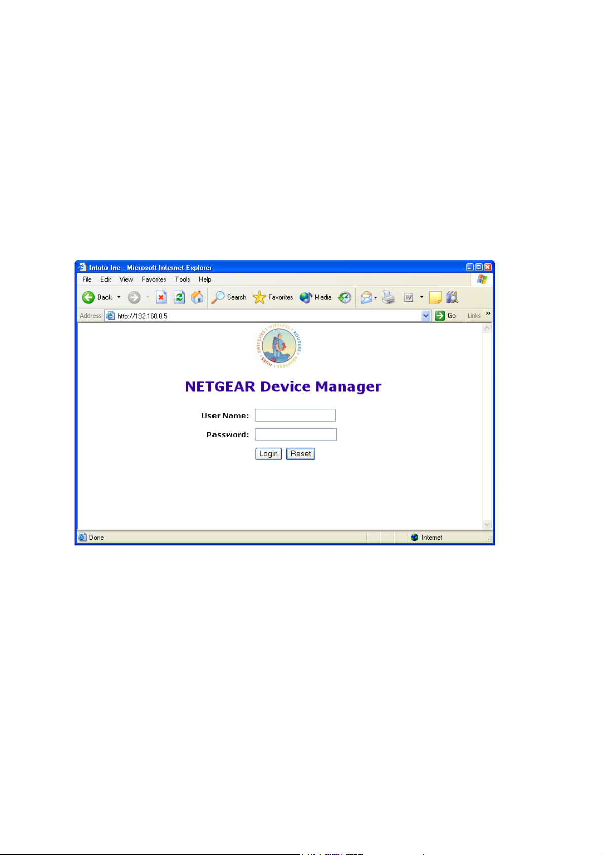
Run a browser, such as, Inetrnet Explorer, and enter in the router’s administration IP address. For
example, “http://192.168.1.1”.
Enter the user name and password (By default, user name is set to “root”. No password – leave the filed
empty).
Successful login brings up the basic settings page.
© NetgearInc. 2004 Page 5 of 36
All Rights Reserved
Page 6
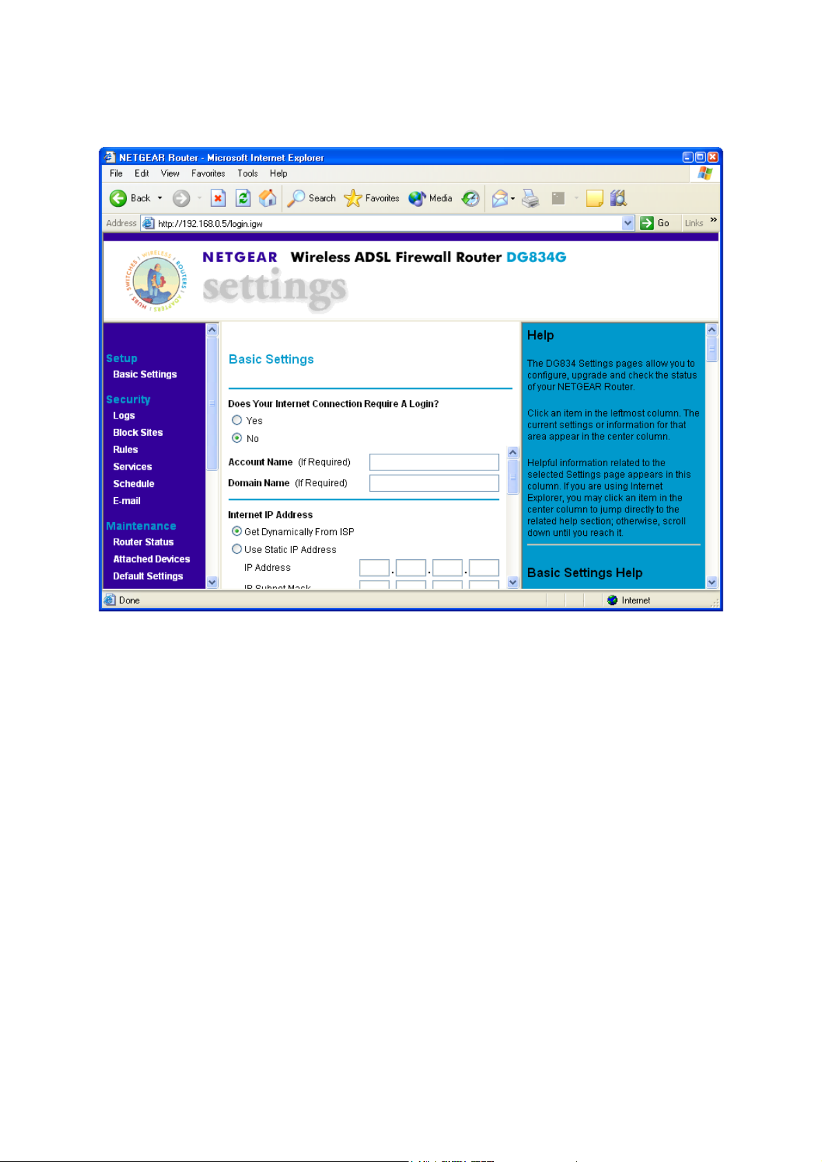
There are 4 component windows here.
1) The title windows, which display the logo, manufacture’s name, box’s name and model
2) The manual window, which shows the list of different setting and configuration pages.
3) Configuration window
4) Help windows, which give detailed explanation of the each field in the setting and configuration
windows.
The WGR826V Settings pages allow you to configure, upgrade and check the status of your
NETGEAR Router.
Click an item in the leftmost column. The current settings or information for that area appear in the
center column.
Helpful information related to the selected Settings page appears in this column. If you are using
Internet Explorer, you may click an item in the center column to jump directly to the related help
section; otherwise, scroll down until you reach it.
© NetgearInc. 2004 Page 6 of 36
All Rights Reserved
Page 7
3.2 Basic Settings
3.2.1 Basic Settings
Note: If you are setting up the Router for the first time, the default settings may work for you with no
changes.
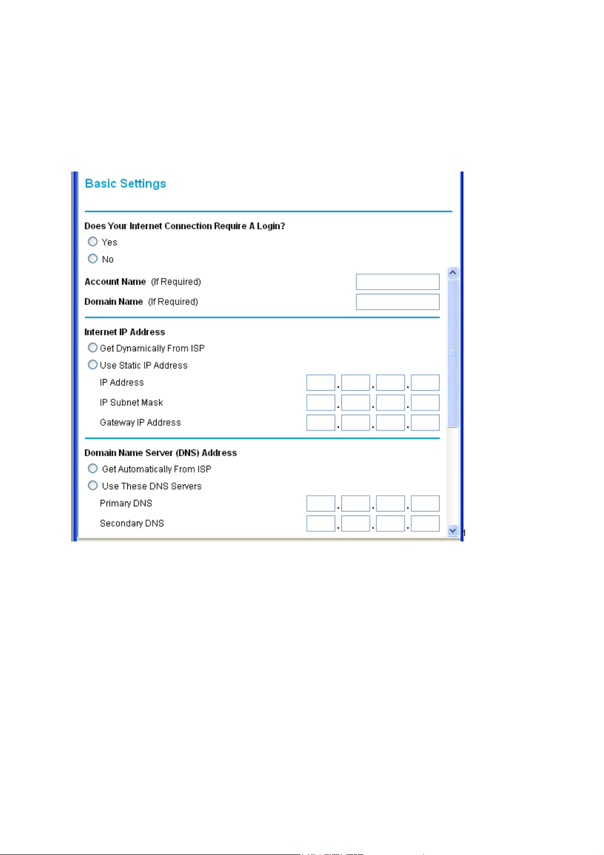
Does Your Internet Connection Require A Login?
Select this option based on the type of account you have with your ISP. If you need to enter login
information every time you connect to the Internet or you have a PPPoE account with your ISP,
select Yes. Otherwise, select No.
© NetgearInc. 2004 Page 7 of 36
All Rights Reserved
Page 8

Note: If you have installed PPP software such as WinPoET (from Earthlink) or Enternet (from
PacBell), then you have PPPoE. Select Yes. After selecting Yes and configuring your Router, you
will not need to run the PPP software on your PC to connect to the Internet.
Account Name
(also known as Host Name or System Name)
For most users, type your account name or user name in this box. For example, if your main mail
account is JerAB@ISP.com, then put JerAB in this box.
If your ISP has given you a specific Host name, then type it (for example, CCA7324-A).
Domain Name
For most users, you may leave this box blank, unless required by your ISP. You may type the
domain name of your ISP. For example, if your ISP's mail server is mail.xxx.yyy.zzz, you would type
xxx.yyy.zzz as the Domain Name.
If you have a Domain name given to you by your ISP, type it in this box. (For example, Earthlink
Cable may require a Host name of 'home' and Comcast sometimes supplies a Domain name.)
Internet IP Address
If you log in to your service or your ISP did not provide you with a fixed IP address, the Router will
find an IP address for you automatically when you connect. Select Get Dynamically From ISP.
If you have a fixed (or static IP) address, your ISP will have provided you with the required
information. Select
Use Static IP Address
and type the IP Address, Subnet Mask and Gateway IP
Address into the correct boxes.
For example:
•
IP Address: 24.218.156.183
• Subnet Mask: 255.255.255.0
•
Gateway IP Address: 24.218.156.1
© NetgearInc. 2004 Page 8 of 36
All Rights Reserved
Page 9
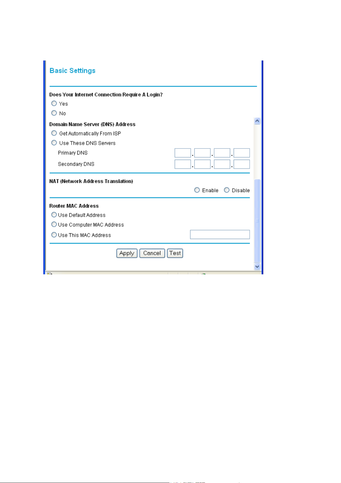
DNS Address
The DNS server is used to look up site addresses based on their names.
If your ISP gave you one or two DNS addresses, select Use These DNS Servers and type the
primary and secondary addresses.
Otherwise, select Get Automatically From ISP.
If you get 'Address not found' errors when you go to a Web site, it is likely that your DNS
Note:
servers aren't set up properly. You should contact your ISP to get DNS server addresses.
NAT (Network Address Translation)
NAT allows all LAN PCs to gain Internet access via this Router, by sharing this Router's WAN IP
address. In most situations, NAT is essential for Internet access via this Router. You should only
disable NAT if you are sure you do not require it. When NAT is disabled, only standard routing is
performed by this Router.
© NetgearInc. 2004 Page 9 of 36
All Rights Reserved
Page 10
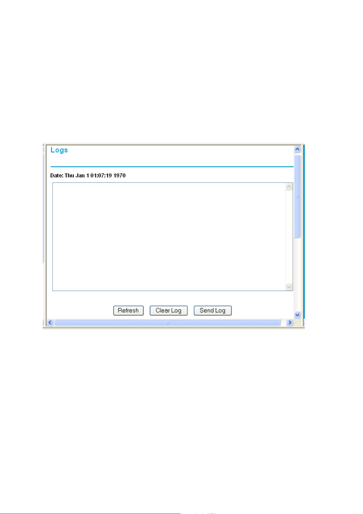
3.2.2 Logs
Your router will log security-related events such as denied incoming service requests, hacker probes,
and administrator logins, according to your settings on this screen.
If you have set up content filtering on the Block Sites page, you can also log when someone on
your network tried to access a blocked site.
If you have E-mail notification on, you'll receive these logs in an E-mail message. If you don't have
E-mail notification set up, you can view the logs here.
To delete all log entries:
•
Click Clear Log.
To see the most recent entries:
• Click Refresh.
To E-mail the log now:
•
Click Send Log.
© NetgearInc. 2004 Page 10 of 36
All Rights Reserved
Page 11
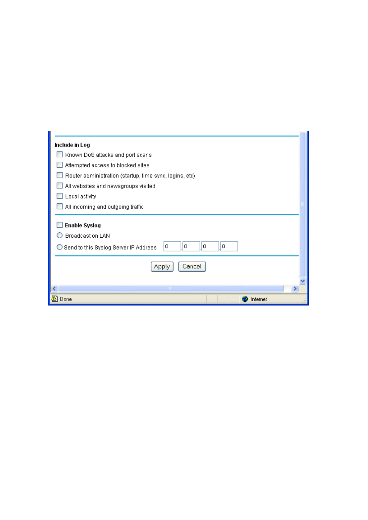
Include in Log
Use these checkboxes to determine which events are included in the log. Checking all options will
increase the size of the log, so it is good practice to disable any events which are not really required.
•
Known DoS attacks and Port Scans - If checked, Denial of Service attacks, as well as port
scans, will be logged.
•
Attempted access to blocked sites - If checked, attempted Internet accesses which were
blocked are logged.
•
Router Administration - If checked, other Router operations (not covered by the selections
above) will be logged.
• All Websites and newsgroups visited - If checked, all visited websites and newsgroups are
logged.
© NetgearInc. 2004 Page 11 of 36
All Rights Reserved
Page 12

•
Local activity - If checked, this will log connections to this Router, rather than through this
Router to the Internet.
•
All incoming and Outgoing traffic - All incoming and outgoing connections are logged.
Checking this will generate a large number of log entries, and is only recommended if using
a Syslog server.
Syslog
Enable one of these three options, as required:
• Disable - Select this if you don't have a Syslog server.
•
Broadcast on LAN - the Syslog data is broadcast, rather than sent to a specific Syslog server.
Use this if you Syslog Server does not have a fixed IP address.
• Send to this Syslog server IP address - If your Syslog server has a fixed IP address, select
this option, and enter the IP address of your Syslog server.
3.2.3 Block sites
If you want to prevent access to certain sites on the Internet, you can use the router's content
filtering feature. You can specify up to 32 words that, should they appear in the website name
(URL) or newsgroup name, will cause the site to be blocked by the router. When users try to
access a blocked site, they will get a message: "Blocked by NETGEAR".
© NetgearInc. 2004 Page 12 of 36
All Rights Reserved
Page 13

Keywords are always blocked.
Note:
To block keywords or Internet domains:
1. Select the Turn keyword blocking on check box.
2. Type a keyword or domain name in the Add Keyword box.
3. Click Add Keyword.
The word or domain name appears in the list below.
4. Continue adding names and keywords until you are finished.
5. Click Apply.
To delete a keyword or domain name:
1. Select the word or domain name in the list.
2. Click Delete Keyword.
3. Continue selecting and deleting names and keywords until you are finished.
4. Click Apply.
© NetgearInc. 2004 Page 13 of 36
All Rights Reserved
Page 14

Note: You may select more than one keyword or domain name at a time by pressing the Shift key
as you select individual entries.
To delete all keywords and domain names:
1. Click Clear List.
2. Click Apply.
To allow one computer to have unrestricted access to the Internet:
1. Type the IP address of the computer in the Trusted IP Address area.
2. Click Apply.
To allow unrestricted access to the Internet:
1. Clear the
2. Click Apply.
Turn keyword blocking on
check box.
3.2.4 Rules
The Firewall will always block DoS (Denial of Service) attacks. A DoS attack does not attempt to
steal data or damage your PCs, but overloads your Internet connection so you can not use it - the
service is unavailable.
As well, you can use this screen to create Firewall rules to block or allow specific traffic. This
feature is for Advanced Administrators only! Incorrect configuration will cause serious
problems.
© NetgearInc. 2004 Page 14 of 36
All Rights Reserved
Page 15

Outbound Services
This lists all existing rules for outbound traffic. If you have not defined any rules, only the default
rule will be listed. The default rule allows all outgoing traffic.
To create a new rule:
1. Click the "Add" button. (It does not matter which radio button is selected)
2. The "Outbound Service" screen will be displayed. This screen has its own help file.
3. Complete the "Outbound Service" screen, and save the data. The new rule will be listed in
the table when you return to this screen.
To make changes to an existing rule:
1. Click the radio button next to an row in the table.
2. Click the button for the desired actions:
o Edit - to make any changes to the rule definition. The "Outbound Service" screen
will be displayed, with the data for the selected rule.
o
Move - to move the selected rule to a new position in the table. You will be
prompted for the new position.
o
Delete - to delete the selected rule.
© NetgearInc. 2004 Page 15 of 36
All Rights Reserved
Page 16

Inbound Services
This lists all existing rules for inbound traffic. If you have not defined any rules, only the default rule
will be listed. The default rule blocks all inbound traffic.
To create a new rule:
1. Click the "Add" button. (It does not matter which radio button is selected)
2. The "Inbound Service" screen will be displayed. This screen has its own help file.
3. Complete the "Inbound Service" screen, and save the data. The new rule will be listed in
the table when you return to this screen.
To make changes to an existing rule:
1. Click the radio button next to an row in the table.
2. Click the button for the desired actions:
o
Edit - to make any changes to the rule definition. The "Inbound Service" screen will
be displayed, with the data for the selected rule.
o Move - to move the selected rule to a new position in the table. You will be
prompted for the new position.
o
Delete - to delete the selected rule.
Respond to Ping on Internet WAN Port
If you want the router to respond to a 'ping' from the Internet, click the Respond to Ping on
Internet WAN Port
box unless you have a specific reason to do so.
check box. This can be used as a diagnostic tool. You shouldn't check this
3.2.5 Services
© NetgearInc. 2004 Page 16 of 36
All Rights Reserved
Page 17

The Rules menu contains a list of predefined Services for creating firewall rules. If a service does
not appear in the predefined Services list, you can define the service in this menu. The new
service will then appear in the Rules menu's Services list.
Service Table
This table lists all Services you have defined. If you have not defined any Services, the table will
be empty.
To Create a Service
1. Click Add Custom Service
2. Enter the data for the service as required.
3. Click Apply to save the new service.
To Edit a Service
1. Click the radio button next to a service in the table.
2. Click Edit Service to display the service's data in the "Service Definition" section.
3. Change the data for the service as required.
4. Click Apply to save your changes.
To Delete a Service
1. Click the radio button next to a service in the table.
2. Click Delete Service to delete the selected service.
© NetgearInc. 2004 Page 17 of 36
All Rights Reserved
Page 18

Service Definition
This section displays data for the current Service, and allows you to enter data to create a new
rule.
Name
Enter a suitable name for this Service.
Type
Select the correct type for this Service.
Start Port
Enter the beginning of the required port range here, and the end of the range in the "Finish Port"
field. If only a single port is required, enter the same number in both "Start" and "Finish" fields.
Finish Port
Enter the end of the requried port range here. If only a single port is required, enter the same
number in both "Start" and "Finish" fields.
3.2.6 Schedule
If you have set Firewall Rules on the "Rules" screen or Keyword Filtering on the "Block Sites"
screen, you can set up a schedule for when the rules are applied.
To apply Rules based on a schedule:
1. On the "Rules" screen, create the required Rules, using either "Block by Schedule" or
"Allow by Schedule" for each rule, as required.
2. Select the Use this schedule for rules checkbox on this screen.
3. Select the days and times on this screen, as required.
4. Click Apply.
Note: If the schedule is disabled on this screen, this affects ALL Rules which are using a schedule.
© NetgearInc. 2004 Page 18 of 36
All Rights Reserved
Page 19

Days
Select the required days
• Every Day - all days will automatically be selected
•
Sunday, Monday .. If "Every Day" is NOT selected, you can choose the required days
individually.
Time of day
This determines when the schedule is applied, for each day selected above. Enter the desired
Start and Finish times.
Enter the values as 24-hour time. For example, 10:30 am would be 10 hours and 30
Note:
minutes and 10:30 pm would be 22 hours and 30 minutes.
© NetgearInc. 2004 Page 19 of 36
All Rights Reserved
Page 20

Timezone
The Router will determine the current time and date by contacting a Network Time (NTP) Server
on the Internet. In order to display your local time, you must select your Time Zone from the list.
If your region uses Daylight Savings Time, you must manually check Adjust for Daylight Savings
Time at the beginning of the adjustment period, and uncheck it at the end of the Daylight Savings
period.
Use this NTP Server
If you prefer to use a particular NTP server as the primary server, check the checkbox Use this
NTP Server and enter the Server's IP address under Use this NTP Server.
If this setting is not enabled, the default NTP Servers are used.
To Accept Or Cancel
Click Apply to save changes.
Click
Cancel
to disregard any unsaved changes.
3.2.7 E-mail
Your router can periodically email you the system log. (On the Logs screen, you can choose what
events are to be included in the log.) The router can also send an immediate alerts when it detects
a significant security incident such as
© NetgearInc. 2004 Page 20 of 36
All Rights Reserved
Page 21

•
A known hacker attack is directed at your IP address
•
A computer on the Internet scans your IP address for open ports
• Someone on your LAN (Local Area Network) tries to visit a blocked site.
If you'd like to have alerts and logs sent to you by e-mail, fill out the settings on this form.
You can always check the logs manually by viewing the Logs page. If you don't want to receive emails, simply leave the Turn e-mail notification on checkbox unchecked.
Send alerts and logs by e-mail
To receive alerts and logs by e-mail:
1. Select the
2. In the Outgoing Mail Server box, type the name or IP address of the outgoing SMTP mail
server of your ISP (for example, mail.myISP.com).
If you leave this box blank, no alerts or logs will be sent to you.
Tip: You used this information when you set up your e-mail program. If you can't
remember it, check the settings in your e-mail program.
3. In the E-mail Address box, type the e-mail address where the alerts and logs will be sent.
Use a full e-mail address (for example, ChrisXY@myISP.com
Turn e-mail notification on
check box above.
).
© NetgearInc. 2004 Page 21 of 36
All Rights Reserved
Page 22

Send E-Mail alerts immediately
If you want E-mail alerts sent immediately whenever a security incident occurs, select the
appropriate checkboxes. If you ONLY want alerts sent, select None for the log schedule below.
Click Apply to have your changes take effect.
3.2.8 Router Status
You can use the Router Status page to check the current settings and statistics for your Router.
This page shows you the current settings. If something needs to be changed, you'll have to
change it on the relevant page.
Account Name: This is the Account Name that you entered in the Setup Wizard or Basic Settings.
Firmware Version: This is the current software the Router is using. This will change if you
upgrade your Router.
© NetgearInc. 2004 Page 22 of 36
All Rights Reserved
Page 23

WAN Port: These are the current settings that you set in the Setup Wizard or Basic Settings
pages.
•
MAC Address - the physical address of the WGR826V, as seen from the Internet.
•
IP Address - current Internet IP address. If assigned dynamically, and no Internet
connection exists, this will be blank or 0.0.0.0
•
DHCP - indicates either Client (IP address is obtained dynamically) or None.
•
IP Subnet Mask - the subnet mask associated with the Internet IP address.
•
Gateway IP Address - the Gateway associated with the Internet IP addrress.
•
Domain Name Server - displayes the address of the current DNS.
LAN Port
•
•
•
•
: These are the current settings, as set in the LAN IP Setup page.
MAC Address - the physical address of the WGR826V, as seen from the local LAN.
IP Address - LAN IP address of the Router.
DHCP - indicates if the WGR826V is acting as a DHCP Server for devices on your LAN.
IP Subnet Mask - subnet mask associated with the LAN IP address.
© NetgearInc. 2004 Page 23 of 36
All Rights Reserved
Page 24

Wireless Port: These are the current settings, as set in the Wireless Settings page.
•
Name (SSID) - SSID of the WGR826V.
•
Region - the location (country).
• Channel - the current channel in use.
•
Wireless AP - indicates if the Access Point feature of the WGR826V is enabled or not. If not
enabled, the Wireless LED on the front panel will be off.
• Broadcast Name - indicates if the WGR826V is broadcasting its SSID.
Click Show Statistics to see Router performance statistics such as the number of packets sent
and number of packets received for each port.
Click Connection Status to see information about your current connection.
© NetgearInc. 2004 Page 24 of 36
All Rights Reserved
Page 25

3.2.9 Attached Devices
This page shows the IP Address, Device Name and MAC (Media Access Control) Address for
each computer attached to the Router.
You cannot change any of the values on this page. To update this page and to show the current
attached devices, click on the Refresh button.
3.2.10 Set Password
Change you user name and password.
© NetgearInc. 2004 Page 25 of 36
All Rights Reserved
Page 26

3.2.11 Diagnostics
You can use this page to perform various diagnostics. For normal operation, these are not
required.
Ping or Trace an IP address
Ping
Use this to send a "ping" packet request to the specified IP address. This is often used to test a
connection. If the request "times out" (no reply is received), this usually means the destination is
unreachable. However, some network devices can be configured not to respond to a ping.
The ping results will be displayed in a new screen; click "Back" to return to the Diagnostics screen.
Trace
Often called "Trace Route", this will list all Routers between the source (this device) and the
destination IP address.
The Trace Route results will be displayed in a new screen; click "Back" to return to the Diagnostics
screen.
© NetgearInc. 2004 Page 26 of 36
All Rights Reserved
Page 27

Perform a DNS Lookup
A DNS (Domain Name Server) converts the Internet name (e.g. www.netgear.com) to an IP
address. If you need the IP address of a Web, FTP, Mail or other Server on the Internet, you can
do a DNS lookup to fing the IP address.
Display the Routing Table
This operation will display the internal routing table. This information is used by Technical Support
and other staff who understand Routing Tables.
Reboot the Router
Use this button to perform a remote reboot (restart). You can use this if the Router seems to have
become unstable or is not operating normally.
Rebooting will break any existing connections either to the Router (such as this one) or
Note
through the Router (for example, LAN users accessing the Internet). However, connections to the
Internet will automatically be re-established when possible.
CPU Utilization
The CPU usage while Voice and Data traffic is flowing through the router can be measured using
XCYCLE utility as follows.
On the Console,
go to /mnt/cramfs
Insmod hrdbr.o
./xcycle
The CPU utilization will be displayed.
© NetgearInc. 2004 Page 27 of 36
All Rights Reserved
Page 28

Use this button to perform a remote reboot (restart). You can use this if the Router seems to have
become unstable or is not operating normally.
3.2.12 Router Upgrade & Provisioning
You install new versions of the Router's software using the Firmware Upgrade page.
Go to the NETGEAR Web site to get new versions of the Router software. After downloading the
file, you'll need to unzip (or unstuff) it before upgrading the Router.
IMPORTANT! Once you click Upload do NOT interrupt the process of sending the software to the
Router and restarting the Router. If you think the process may be interrupted in some way, click
Cancel to keep the current Router software.
To upgrade Router software:
1. Go to www.NETGEAR.com and download the updated software.
2. If not done automatically, uncompress the file.
You may want to read the Release Notes before continuing.
3. Click Browse.
4. Locate and select the file you just downloaded and uncompressed.
5. Click Upload to send the software to the Router.
This loads the new software in the Router and causes the Router to restart.
Note: Do not try to go online, turn off the Router, shutdown the computer or do anything
else to the Router until the Router finishes restarting! When the Ready light stops blinking,
wait a few more seconds before doing anything.
6. Click Router Status and check the Firmware Version to verify that your Router now has the
new software installed.
© NetgearInc. 2004 Page 28 of 36
All Rights Reserved
Page 29

IMPORTANT! In some cases, such as a major upgrades, you may need to reconfigure your
Router after upgrading it. Refer to the Release Notes included with the software to find out if you
need to reconfigure the Router.
If you are unable to successfully upgrade using this method, refer to the Reference Manual on the
WGR826V Resource CD for other ways to upgrade the Router.
Provisioning of TA:
TA contacts a provisioning server for dynamic configuration of VoIP parameters. Configuration, image
upgrade, interface address change notifications are carried over automatically by TA. When the TA boots
up, it first tries to contact Provisioning server (SASVP) and get the latest configuration file. It configures
VoIP stack with the configuration and make voice ports UP.
It need to register TA with SASVP in order to download the configuration and image updates. This is done
by customer in the first time when he buys the box.
The general procedure to register or create an account with a Provisioning server is:
1) The user connects TA to ISP and brings up the Internet connection.
2) Then he configures NAT on the TA and uses TA as edge router.
© NetgearInc. 2004 Page 29 of 36
All Rights Reserved
Page 30

He browses SASVP sever on any Internet browser from his PC connected back on TA and using TA as
router. When he activates his account, TA receives an authentication key, which will be used in
subsequent communications with SASVP server. The authentication key in stored in securely, so that
successive reboots of TA doesn't erase authentication key.
For testing purposes, one can activate an account for testing by going to the following link from any web
browser. This can be done even when TA is not connected in the path for Internet.
https://12.0.37.209/att/auth/auth.pl?ip=66.80.10.151&tn=7323684360
Replace ip = xxx.yyy.zzz.aaa with whatever address TA will communicate with SASVP. This would be the
address of WAN interface of TA.
Replace tn = xyzabcpqrs with what ever telephone number assigned for you for testing. This would be
assigned by Voice service providers.
Trouble shooting and Log:
You can view and enable trouble shooting on TA , if you want to see what is going on between TA and
provisioning server. For this you need access to TA console.
Connect a serial cable to console port of TA ( baud rate 115200).
Press "return" key on the keyboard. You should get linux bash prompt (#)
Enter cli from the bash prompt. You will get WGR826V's CLI prompt.
#cli
**************************************************************
Welcome To The iGateway Command Line Interface
**************************************************************
VoIP initialized sip@8882 cp@8884 on 127.0.0.1
To change the current settings you may run /config/voip/deinit && /config/voip/
init...
iGateway:/>
Enter the following commands from iGateway CLI prompt.
iGateway:/>traceenable PRVD
TRACING FOR PRVD IS ENABLED AS 1
iGateway:/>tracestart
TRACING HAS BEEN STARTED BEFOREHAND
iGateway:/>traceset all
GLOBAL TRACE LEVEL IS ALL WITH LEVEL NUMBER 1
iGateway:/>
"Traceenable" command enables tracing for PRVD daemon . This daemon communicates with
Provisioning server time to time for configuration and image updates.
© NetgearInc. 2004 Page 30 of 36
All Rights Reserved
Page 31

For VoIP trace, enable trace for the VoIP module using the following command :
iGateway:/>traceenable VOIP
iGateway:/>tracestart
iGateway:/>traceset all
Dump of Config File
You can see the dump of Config File received from SASVP.
From bash prompt,
#cat /igateway/prvdump
XML Message Logs
You can see the XML message exchanges between TA and SASVP.
From bash prompt,
#tail- f /igateway/prvexdmp
To see all the messages from the beginning
#cat /igateway/prvexdmp
© NetgearInc. 2004 Page 31 of 36
All Rights Reserved
Page 32

The URL to communicate to SASVP can be set by browsing to TA and clinking on "Router upgrade and
Provisiong" link. You should see four sections in the page. In "Automatic Provisioning" , you can modify
the URL for SASVP server . This URL is used to communicate with SASVP server.
"Upload SASVP CA Certificate " section is used to upload CA certificate to TA . This CA certificate is
used by TA for authenticating SASVP server. Have the CA certificate in the local folder of the PC from
where you accessed this page and click on browse button to give the certificate path in your PC and click
on "upload" button.
"Erase Provisioning Authentication Key" section is used to erase authentication key from the TA. This
causes TA to start the communication with SASVP server from the beginning, as if the box is purchased
new. Use this with caution, as this requires setting up new account with VOIP service provider.
"Firmware Upgrade" section is used to upgarde the image on TA, if the image is available on the
harddisk of local PC. The user can download the images out of band to his local PC and use "browse"
button to select the image and upload it to TA.
3.2.13 LAN IP Setup
The DHCP and TCP/IP default values work for most users.
© NetgearInc. 2004 Page 32 of 36
All Rights Reserved
Page 33

LAN TCP/IP Setup
These are advanced settings that you may configure if you are a network administrator and your
network contains multiple Routers. If you make any changes to these settings you will need to
restart your computer(s) for the settings to take effect.
•
IP Address: Type the IP address of your Router in dotted decimal notation (factory default:
192.168.0.1).
•
IP Subnet Mask: The subnet mask specifies the network number portion of an IP address.
Your Router will automatically calculate the subnet mask based on the IP address that you
assign. Unless you are implementing subnetting, use 255.255.255.0 as the subnet mask
(computed by the Router).
•
RIP Direction: RIP (Routing Information Protocol, RFC1058 and RFC1389) allows a
Router to exchange routing information with other Routers. The RIP Direction selection
controls how the Router sends and receives RIP packets. Both is the default.
o
When set to Both or Out Only, the Router will broadcast its routing table
periodically.
o When set to Both or In Only, it will incorporate the RIP information that it receives.
© NetgearInc. 2004 Page 33 of 36
All Rights Reserved
Page 34

o
When set to None, it will not send any RIP packets and will ignore any RIP packets
received.
•
RIP Version: This controls the format and the broadcasting method of the RIP packets that
the Router sends. (It recognizes both formats when receiving.) By default, this is set for
RIP-1.
o
RIP-1 is universally supported. RIP-1 is probably adequate for most networks,
unless you have an unusual network setup.
o RIP-2 carries more information. Both RIP-2B and RIP-2M send the routing data in
RIP-2 format.
RIP-2B uses subnet broadcasting.
RIP-2M uses multicasting. (See note below.)
Multicasting can reduce the load on non-Router machines because they do not listen to the
Note:
RIP multicast address and will not receive the RIP packets. However, if one Router uses
multicasting, then all Routers on your network must use multicasting.
Use Router As DHCP Server
The WGR826V Router is set up by default as a DHCP (Dynamic Host Configuration Protocol)
Server, which provides the TCP/IP configuration for the all the computers that are connected to
the Router.
Unless told to change these settings by your ISP, leave the
box checked.
If your ISP has you clear this check box, you must have another DHCP server within your network
or else you must manually configure the computer.
•
Starting IP Address: This box specifies the first of the contiguous addresses in the IP
address pool. 192.168.0.2 is the default start address.
• Ending IP Address: This box specifies the last of the contiguous addresses in the IP
address pool. 192.168.0.254 is the default ending address.
Address Reservation
When you specify a reserved IP address for a PC on the LAN, that PC will always receive the
same IP address each time it accesses the DHCP server. Reserved IP addresses should be
assigned to servers that require permanent IP settings.
To Reserve An IP Address:
1. Click the Add button.
2. Input the IP address, MAC address and device name that are to be reserved.
3. Click the Add button when finished.
Use Router As DHCP Server
check
To Edit A Reserved IP Address:
© NetgearInc. 2004 Page 34 of 36
All Rights Reserved
Page 35

1. Select the radio button next to the reserved address you want to edit.
2. Click the Edit button.
3. Edit the IP Address, MAC Address or Device Name.
4. Click the Accept button when finished.
To Delete A Reserved IP Address:
1. Select the radio button next to the reserved address you want to delete.
2. Click the Delete button.
To Save Or Cancel Changes
Click Apply to save the new settings to the Router.
Click Cancel to disregard any unsaved changes.
3.2.14 Static Route
Static routes give the router information that it cannot learn automatically through other means. This
can happen when RIP is disabled on the LAN. (See the LAN IP Setup page.) All defined static routes
appear in the table. To add or delete a route, work in the area under the IP Static Routes table.
© NetgearInc. 2004 Page 35 of 36
All Rights Reserved
Page 36

To set up a static route:
1. Click the Add button.
2. Type a route name for this static route in the Route Name box under the table.
(This is for identification purpose only.)
3. Select Active to make this route effective.
4. Select Private if you want to limit access to the LAN only. The static route will not be
reported in RIP.
5. Type the Destination IP Address of the final destination.
6. Type the IP Subnet Mask for this destination.
If the destination is a single host, type 255.255.255.255.
7. Type the
8. Type a number between 2 and 15 as the Metric value.
This represents the number of routers between your network and the destination.
9. Click Apply to have the static route entered into the table.
To edit or delete a static route:
1. Click the button next to route you want to edit or delete.
2. Click Edit or Delete.
3. Click Apply when finished.
Gateway IP Address
, which must be a router on the same segment.
© NetgearInc. 2004 Page 36 of 36
All Rights Reserved
 Loading...