

Page 1
WGE111
Page 2

Table of Contents
Connecting the Bridge to a Single Device . . . . . . . . . . . . . . . . . . . . . . . .4
Connecting the Bridge to Multiple Devices . . . . . . . . . . . . . . . . . . . . . .5
Identifying Your Wireless Network Settings . . . . . . . . . . . . . . . . . . . . . .7
Connecting the Bridge to a Computer . . . . . . . . . . . . . . . . . . . . . . . . . .8
Checking and Changing the Computer’s IP Address . . . . . . . . . . . . . . . .8
Changing the Bridge’s IP Address . . . . . . . . . . . . . . . . . . . . . . . . . . . . . .10
Using the NetBIOS Name . . . . . . . . . . . . . . . . . . . . . . . . . . . . . . . . . . .11
Changing the Country/Region Setting . . . . . . . . . . . . . . . . . . . . . . . . . .12
Selecting a Specific Wireless Network . . . . . . . . . . . . . . . . . . . . . . . . . . .13
Changing the Bridge’s Password . . . . . . . . . . . . . . . . . . . . . . . . . . . . . . .13
Enabling WEP Security . . . . . . . . . . . . . . . . . . . . . . . . . . . . . . . . . . . . .14
Upgrading the Bridge . . . . . . . . . . . . . . . . . . . . . . . . . . . . . . . . . . . . . .15
Configuring the Bridge for Ad Hoc Mode . . . . . . . . . . . . . . . . . . . . . . .16
Setting the Bridge’s Data Rate . . . . . . . . . . . . . . . . . . . . . . . . . . . . . . . .17
1: Preparing to Install the WGE111 Bridge . . . . . . . . . . . . . . . . . . . . . . . . . .1
Introduction . . . . . . . . . . . . . . . . . . . . . . . . . . . . . . . . . . . . . . . . . . . . .1
Package Contents . . . . . . . . . . . . . . . . . . . . . . . . . . . . . . . . . . . . . . . . .1
System Requirements . . . . . . . . . . . . . . . . . . . . . . . . . . . . . . . . . . . . . .2
Placement and Range Guidelines . . . . . . . . . . . . . . . . . . . . . . . . . . . . . .2
Operating Modes . . . . . . . . . . . . . . . . . . . . . . . . . . . . . . . . . . . . . . . . .2
WGE111 Default Wireless Configuration Settings . . . . . . . . . . . . . . . . .3
2: Installing the WGE111 Bridge . . . . . . . . . . . . . . . . . . . . . . . . . . . . . . . . . .4
3: Preparing to Configure the WGE111 Bridge . . . . . . . . . . . . . . . . . . . . . . . .7
4: Configuring the WGE111 Bridge for Your Wireless Network . . . . . . . . . . .12
WGE111 Bridge Status Lights and Settings . . . . . . . . . . . . . . . . . . . . . . . . . .18
WGE111 Bridge Status Lights . . . . . . . . . . . . . . . . . . . . . . . . . . . . . . . .18
Restoring the Bridge to the Default Settings . . . . . . . . . . . . . . . . . . . . . .18
WGE111 Bridge Status Information . . . . . . . . . . . . . . . . . . . . . . . . . . .19
Troubleshooting Tips . . . . . . . . . . . . . . . . . . . . . . . . . . . . . . . . . . . . . . . . . . .20
WGE111 Bridge System Requirements and Specifications . . . . . . . . . . . . . . . .22
Page 3

Regulatory Approvals
FCC Statement
This equipment has been tested and found to comply with the limits for a Class B digital
device, pursuant to Part 15 of the FCC Rules. These limits are designed to provide reasonable
protection against harmful interference in a residential installation.
This equipment generates, uses and can radiate radio frequency energy and, if not installed and
used in accordance with the instructions, may cause harmful interference to radio communications. However, there is no guarantee that interference will not occur in a particular installation.
If this equipment does cause harmful interference to radio or television reception, which can be
determined by turning the equipment off and on, the user is encouraged to try to correct the
interference by one of the following measures:
Reorient or relocate the receiving antenna.
Increase the separation between the equipment and receiver.
Connect the equipment into an outlet on a circuit different from that to which the receiver
is connected.
Consult the dealer or an experienced radio/TV technician for help.
To assure continued compliance, any changes or modifications not expressly approved by the
party responsible for compliance could void the user's authority to operate this equipment.
(Example - use only shielded interface cables when connecting to computer or peripheral
devices).
FCC Radiation Exposure Statement
This equipment complies with FCC RF radiation exposure limits set forth for an uncontrolled
environment. This equipment should be installed and operated with a minimum distance of 20
centimeters between the radiator and your body.
This device complies with Part 15 of the FCC Rules. Operation is subject to the following two
conditions:
(1) This device may not cause harmful interference, and
(2) This device must accept any interference received, including interference that may cause
undesired operation.
This transmitter must not be co-located or operating in conjunction with any other antenna or
transmitter.
The antennas used for this transmitter must be installed to provide a separation distance of at
least 20 cm from all persons and must not be co-located or operating in conjunction with any
other antenna or transmitter.
Channel
The Wireless Channel sets the radio frequency used for communication.
•Access Points use a fixed Channel. You can select the Channel used. This allows you to
choose a Channel which provides the least interference and best performance. In the USA
and Canada, 11 channel are available. If using multiple Access Points, it is better if adjacent
Access Points use different Channels to reduce interference.
• In "Infrastructure" mode, Wireless Stations normally scan all Channels, looking for an
Access Point. If more than one Access Point can be used, the one with the strongest
signal is used. (This can only happen within an ESS.)
• If using "Ad-hoc" mode (no Access Point), all Wireless stations should be set to use the
same Channel. However, most Wireless stations will still scan all Channels to see if there
is an existing "Ad-hoc" group they can join.
Page 4
Preparing to Install the WGE111 Bridge
Note: If you have a wired network, you must have a wireless router or access point set up in the
network. To connect more than one device to the bridge you must use switch or a hub.
This guide shows you how to connect the bridge and configure it for your network — whether
to work with a wireless router or access point, or to work with other wireless devices. Setup is
easy – follow the instructions in this guide and your network will be up and running quickly.
Package Contents
1
1
Introduction
Thank you for purchasing a NETGEAR WGE111 54 Mbps Wireless Ethernet Bridge. With
this bridge you can connect one or more gaming consoles, personal computers, printers, or
other Ethernet-enabled devices to communicate with your network.
Power adapter
Resource CD for 54 Mbps
Wireless Ethernet Bridge,
Installation guide,
Support information card,
Warranty card
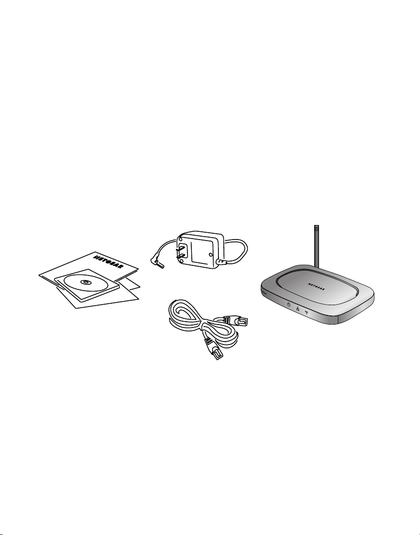
The product package should contain the following items:
100 Mbps
Ethernet cable
WGE111 54 Mbps
Wireless Ethernet Bridge
• WGE111 54 Mbps Wireless Ethernet Bridge
• Power adapter
• Ethernet cable
•
WGE111 54 Mbps Wireless Ethernet Bridge Resource CD, that includes this Reference
Manual for the Model WGE111 54 Mbps Wireless Ethernet Bridge in Adobe
PDF file format
• Installation guide
• Warranty card
• Support information card
®
Acrobat
®
1
Page 5

System Requirements
Placement and Range Guidelines
Operating Modes
2
Before installing the WGE111 54 Mbps Wireless Ethernet Bridge, please make sure that these
minimum requirements have been met:
• For connecting into a wired network, you must have the network set up and working with
an access point or wireless router.
• For creating an Ad-Hoc network without an access point, all devices must have a
receiver/transmitter. (The receiver/transmitter may be another WGE111 bridge.)
If the default settings on the bridge do not work, you will need to configure the bridge. Also, if
you have more than one WGE111 in the network, only one can use the default IP address.
Yo u’ll have to configure the others with unique IP addresses. To configure the bridge with the
configuration software, you must have a personal computer with Internet browser software
installed, such as Microsoft
®
Internet Explorer 5.0 (or later) or Netscape®6.0 (or later).
Computers and other Ethernet-enabled devices can connect over wireless networks indoors at
more than 500 feet. However, the operating distance or range of your wireless connection can
vary significantly based on the physical location of the WGE111 54 Mbps Wireless Ethernet
Bridge. For best results, avoid potential sources of interference, such as:
• Large metal surfaces
• Microwaves
• 2.4 GHz cordless phones
In general, wireless devices can communicate through walls. However, if the walls are
constructed with concrete or have metal (or metal mesh), the effective range will decrease if
such materials are between the wireless devices.
The WGE111 Wireless Ethernet Bridge operates in either Infrastructure or Ad-Hoc mode.
• Infrastructure mode is used when you have an access point or wireless router connected to
a wired network. The wireless devices and computers communicate with the wired
network (and other wireless devices) through the wireless router or access point. For
example, with a wireless router multiple computers (both wired and wireless) can share a
single cable or DSL broadband Internet connection.
• You use the bridge in Ad-Hoc mode if you have a small, wireless-only network and all the
devices have wireless transmitters/receivers. In this case, there’s no need for an access point
or a wireless router for the wireless devices communicate directly to one another.
Page 6

WGE111 Default Wireless Configuration Settings
• Password: password
• Authentication type: Auto
• WEP security: Disabled
• Protocol: Static
• Device name: netgearxxxx (where xxxx is the last 4 digits of the MAC address)
• Data rate: b/g combo
3
Note: If you are setting up a new wireless network, please set up the network and make sure it
before adding the WGE111 Wireless Ethernet Bridge into the network.
works
You will need to identify the wireless configuration and security parameters already defined in
your wireless network.
Note: All NETGEAR, Inc. 802.11g and 802.11b wireless access products use similar factory
settings as the WGE111 and will work without any configuration changes.
The factory default settings for your WGE111 54 Mbps Wireless Ethernet Bridge are:
• Mode (Infrastructure or Ad-Hoc): Infrastructure
• Wireless network name Service Set Identification (SSID): Any
Note: Any means the bridge will connect to the access point or wireless router that has the
strongest signal. This may not be the closest access point or wireless router. For the WGE111
Wireless Ethernet Bridge to communicate with a specific wireless router or access point, both
devices must be configured with the same SSID.
• User ID:
• Country/Region: United States
Warning: Having the bridge set to the wrong country or region may result in the violation of
local laws.
WGE111-specific default settings:
• IP address: 192.168.0.202
admin
Page 7
Connecting the Bridge to a Single Device
Warning: Failure to follow these guidelines can cause intermittent or complete failure
of wireless connectivity.
• Place it in an elevated location such as a high shelf or on a wall in the center of
your wireless access area. If you mount the bridge on a wall, do not place the bridge
in such a way that it is vertical with the NETGEAR name upside-down and the power
adapter plug hanging from the bottom of the unit. Having the unit in this position
violates power adapter regulations.
3. Lift the bridge’s antenna so it is vertical.
4
2
2
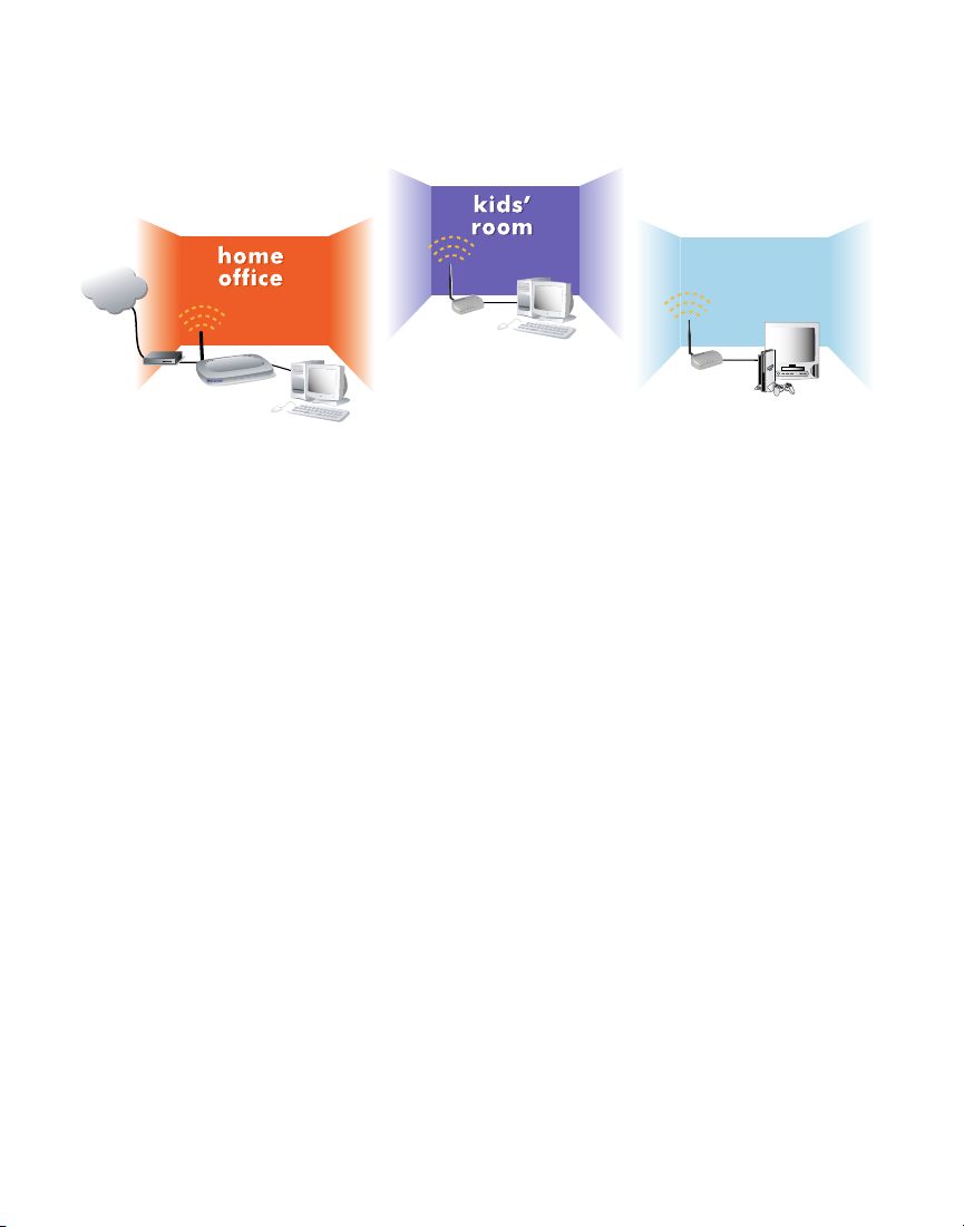
Internet
Installing the WGE111 Bridge
family
family
room
room
Macintosh computer with
WGE111 54 Mbps Wireless
Ethernet Bridge
Gaming console with
WGE111 54 Mbps Wireless
Ethernet Bridge
Cable/DSL
modem
R
A
E
G
T
E
N
WGR814 54 Mbps
Cable/DSL
Wireless Router
3
Desktop PC with
Ethernet connection
This section provides instructions for connecting the WGE111 54 Mbps Wireless Ethernet
Bridge, using the default settings, to either a single Ethernet-enabled device or to multiple
devices through a switch or hub.
Note: If you find that the default settings don’t work, if you know that you’ve configured your
wireless network with WEP security, if you’re placing more than one WGE111 bridge on the
network, or if you are not in the United States, you’ll have to configure the bridge before
connecting it to the Ethernet-enabled device(s). To configure the bridge, see
WGE111 Bridge for Your Wireless Network
on page 12.
Configuring the
1. Unpack the box and verify the contents.
2. Identify a flat surface where you will put the wireless game adapter. For best results, follow
these guidelines:
• Place it away from potential sources of interference, such as computers, monitors,
TVs, microwaves, cordless phones, or large metal surfaces.
Page 8
Connecting the Bridge to Multiple Devices
Warning: Failure to follow these guidelines can cause intermittent or complete failure
of wireless connectivity.
• Place it in an elevated location such as a high shelf or on a wall in the center of
your wireless access area. If you mount the bridge on a wall, do not place the bridge
in such a way that it is vertical with the NETGEAR name upside-down and the power
adapter plug hanging from the bottom of the unit. Having the unit in this position
violates power adapter regulations.
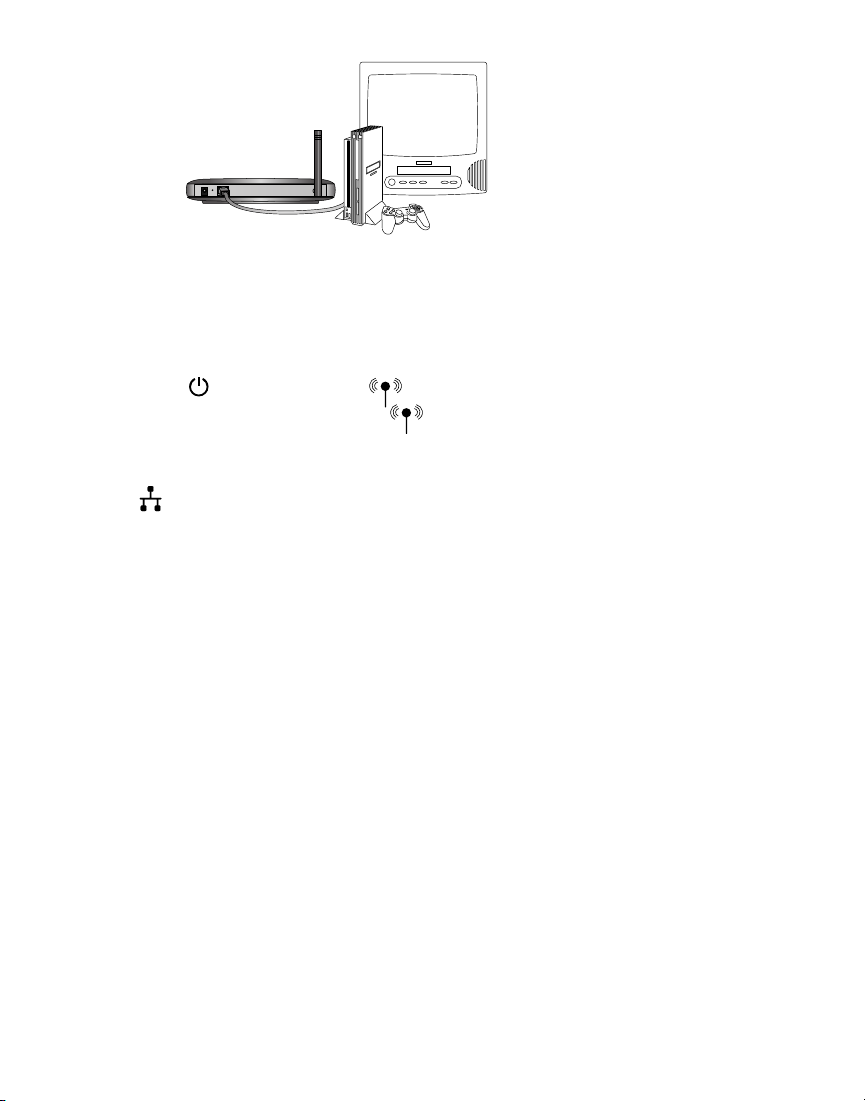
3. Lift the bridge’s antenna so it is vertical.
4. Turn off the gaming consoles or other Ethernet-enabled devices.
WGE111 54 Mbps
5
Wireless Ethernet Bridge
Gaming console or other
Ethernet-enabled device
4. Turn off the gaming console or other Ethernet-enabled device.
5. Connect the provided Ethernet cable between the WGE111 Wireless Game Adapter and the
gaming console or other Ethernet-enabled device.
6. Connect the power adapter to the bridge and plug the power adapter in to a power outlet.
The Power and Wireless LAN lights should light up.
7. After you see the Wireless LAN light light up, turn on the gaming console or other
Ethernet-enabled device.
If the bridge and the Ethernet-enabled device are successfully connected, the Network
light will light up. This light flashes when there is network activity.
Note: If your setup works with the default settings, you don’t need to configure the bridge
unless you need to change the Country/Region setting from the default setting (United States)
or you need to assign a unique IP address to subsequent WGE111 bridges. See page 12 for
information on configuring the bridge.
1. Unpack the box and verify the contents.
2. Identify a flat surface where you will put the wireless game adapter. For best results, follow
these guidelines:
• Place it away from potential sources of interference, such as computers, monitors,
TVs, microwaves, cordless phones, or large metal surfaces.
Page 9
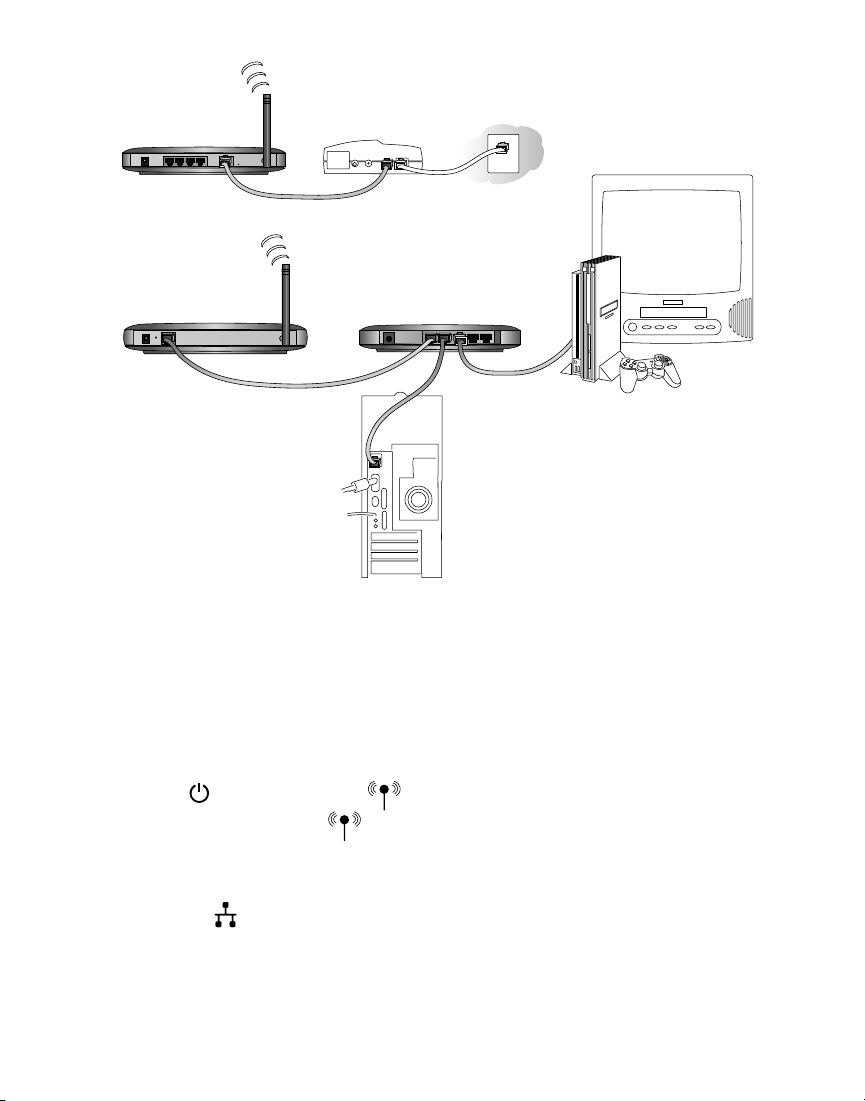
WGR614 54 Mpbs
Wireless Router
Cable
or DSL
modem
WGE111 54 Mbps
Wireless Ethernet Bridge
Fast Ethernet
Switch FS605
Ethernet-enabled
computer
Gaming console or other
Ethernet-enabled device
5. Connect the provided Ethernet cable between the WGE111 Wireless Game Adapter and the
switch (or hub).
6. Connect each gaming console or other Ethernet-enabled device to the switch (or hub)
using an Ethernet cable.
7. Connect the switch’s (or hub’s) power adapter and plug that power adapter in to a power
outlet.
8. Connect the bridge’s power adapter and plug the power adapter in to a power outlet.
The Power and Wireless LAN lights should light up.
9. After the Wireless LAN light lights up, turn on any gaming console(s).
10. After turning on any gaming consoles, turn on any other Ethernet-enabled device(s).
If the bridge, switch, and the Ethernet-enabled devices are successfully connected, the
Network light will light up. This light flashes when there is network activity.
Note: If your setup works with the default settings, you don’t need to configure the bridge
unless you need to change the Country/Region setting from the default setting (United States)
or you need to assign a unique IP address to subsequent WGE111 bridges. See page 12 for
information on configuring the bridge.
6
Page 10

Preparing To Configure the WGE111
Identifying Your Wireless Network Settings
You may want to print this page separately, fill in the configuration parameters, and put it in a
safe place for possible future reference. For an existing wireless network, the person who set up
the network will be able to provide this information.
disabled. If you have set up WEP security on your wireless network (through the router or
access point), you’ll need to configure the bridge using the same WEP security parameters.
WEP Encryption Key Length, circle one: 40/64 or 128 bits
WEP Encryption Passphrase, if used: ___________________
A passphrase is used to automatically generate the WEP hexadecimal numbers for the key.
Otherwise, you will have to manually enter up to four hexadecimal numbers.
WEP Hexadecimal Numbers: ______________________________
______________________________
______________________________
______________________________
7
3
3
If the default settings don’t work in your wireless network, if you are in a country or region
other than the United States, or if you have multiple WGE111 bridges on the network, you
need to configure the bridge.
Bridge
Note: For wireless devices and the bridge to communicate with each other, each must be
configured with the same SSID, WEP security settings, and the same IP subset address.
• Wireless Network Name (SSID): The Service Set Identification (SSID) identifies the
wireless local area network.
wireless network with a different SSID, write your network’s SSID on the line below.
Wireless network name (SSID): ______________________________
•
Bridge IP Address: Your Ethernet network has an IP subset address given as a set of three
numbers plus a last set of unique numbers (xxx.xxx.xxx.yyy) to identify each device on the
network. The default IP address for the bridge is
Ethernet network, each bridge must have a unique address consistent with your network’s IP
subset address. If you need to change the bridge’s IP address, write down the new address.
Bridge’s IP address: ______________________________
Any is the default WGE111 SSID. If you have named your
192.168.0.201. To communicate to your
•
WEP Security Encryption key: The default WEP encryption mode of the bridge is
Page 11

Connecting the Bridge to a Computer
Checking and Changing the Computer’s IP Address
If your wireless network has an IP address other than 192.168.0.yyy, you need to change the IP
address on the computer before you can access the browser-based configuration software.
Note: All NETGEAR products use 192.168.0.yyy. If you have NETGEAR wireless products
working in your wireless network without configuration changes, you won’t need to check or
change IP addresses.
Windows 98/Me
1. Choose Settings>Control Panel from the Start menu.
2. Double-click the
Network icon.
3. Click the
Configuration tab.
4. In the list of installed network
components, select the TCP/IP entry for
the computer’s Ethernet adapter or NIC.
5. Click
Properties.
6. Click the IP Address tab.
7. If
Obtain an IP address automatically is
selected, select Specify an IP Address.
OR
If
Specify an IP Address is already
selected, note the current IP address.
8. Change the IP address to
192.168.0.230.
8
You use browser-based configuration software to configure the bridge. To access the software, the
bridge must be directly connected or connected through a switch (or hub) to a computer. The
computer must have an Internet browser installed. For example, if the bridge is connected to a
game box, you’ll have to connect the bridge to a computer to be able to configure the bridge.
To connect the bridge to a computer:
1. If your network has a wireless router or access point,
make sure it is powered up.
2. Power down the Ethernet-enabled computer.
3. Connect the provided Ethernet cable between the
computer and the bridge.
4. Power up the bridge.
5. Power on the computer.
WGE111 54 Mpbs
Wireless Ethernet Bridge
Page 12

9. Click OK twice to close the Network control panel and save any changes.
10. If you made a change, restart the computer.
Note: After you’ve changed the settings on the bridge, you’ll have to reset the TCP/IP
Properties: IP Address tab values back to their original state.
Windows 2000/XP
1. Right-click My Network Place and choose
Properties.
2. Double-click Local Area Network Connection and
click Properties.
3. Select Internet Protocol (TCP/IP) and click
Properties.
4. If Obtain an IP address automatically is selected,
select Use the following IP Address.
OR
If Use the following IP Address is selected, note
the current IP address.
5. Change the IP address to
192.168.0.230.
6. Click OK twice and click Close to save any
changes.
7. If you made a change, restart the computer.
Note: After you’ve changed the settings on the bridge, you’ll have to reset the Internet Protocol
(TCP/IP) Properties
dialog box back to its original state.
Mac OS®8.6 or 9.x
1. Choose Control Panels >TCP/IP from the
Apple () menu.
2. If not already selected, select
Ethernet in the
Connect via list.
3. If Manually isn’t selected in the Configure list,
note the current selection and select Manually.
OR
If Manually is selected, note the current IP
address.
4. Change the IP address to 192.168.0.230 and
click the close box.
5. If asked, click
Save.
9
Page 13

Note: After you’ve changed the settings on the bridge, you’ll have to reset the TCP/IP dialog
box back to its original state.
Mac OS X
1. Choose System Preferences from the Apple
() menu.
2. Double-click Network.
3. If not already selected, select Built-in
Ethernet in the Configure list.
4. If
Manually isn’t selected in the Configure list,
note the current selection and select Manually.
OR
If Manually is selected, note the current IP
address.
5. Change the IP address to 192.168.0.230 and
click Apply Now.
Note: After you’ve changed the settings on the bridge, you’ll have to reset the Network: TCP/IP
dialog box back to its original state.
Linux®and UNIX
®
If you’re configuring the bridge with a Linux-based or UNIX-based computer see your system
documentation for TCP/IP and networking setup information.
Changing the Bridge’s IP Address
1. Start your browser software.
2. Type
http://192.168.0.201 as the web address and press Enter (or Return).
3. Type admin as the User ID and type password as the Password.
4. Click OK.
Yo u’ll see the Status page.
5. To change the IP address for the bridge to match your wireless network, click IP Settings.
6. Select
Use this IP address and type a unique IP address for the bridge. The first three sets
of numbers (xxx.xxx.xxx.yyy) should be the same as your access point or router. The last
set of numbers (.yyy) should be a set of unique numbers on your network.
OR
If your network has a router with a router table, change the Protocol to
DHCP.
(By doing this, the bridge’s IP address is assigned dynamically by the router and you’ll use
the router table to find out what the bridge’s current IP address is.)
10
Page 14

8. Click Apply.
9. Click
Logout.
10. Restore the computer to its previous
network settings. See Checking and
Changing the Computer’s IP Address
on page 8 for details.
11. Make any other configuration
changes.
12. If you want this bridge used
elsewhere on your network, install
it now.
Using the NetBIOS Name
11
Note: If you have multiple WGE111 bridges in your network and want to use the default IP
address of 192.168.0.201, only one bridge can use this default IP address. You’ll have to create
IP addresses for each bridge using 192.168.0.yyy, where yyy is a unique number for each
device.
If you’re familiar with using a device’s NetBIOS name, you may use it in the Internet browser
instead of the IP address to access the configuration software. The WGE111 NetBIOS name is
netgearxxxx, where xxxx stands for the last four digits of the WGE111 MAC address, which is
found on the bridge’s label.
Page 15

Configuring the WGE111 Bridge for Your
Changing the Country/Region Setting
If you are not in the United States, you must first change the Country/Region selection.
1. Start your browser software.
2. Type
http:// followed by the bridge’s IP address as the web address and press Enter (or
Return).
Note: The default value is 192.168.0.201. If you’ve set the bridge to use DHCP, check the
router table to find out what the current address is for the bridge.
3. Type
admin as the User ID and type
password as the Password.
4. Click
OK.
Yo u’ll see the Status page.
5. Click
Wireless Settings.
6. Select the correct country or region
from the Country/Region list. Click
Yes to accept the new country or
region.
Warning: Having the bridge set to the
wrong country or region may result in
the violation of local laws.
7. Click
Apply.
8. Click OK.
9. If you are through making changes, click Logout.
12
4
4
You use browser-based configuration software to configure the bridge. To do so, you must have
the bridge connected to a computer (either directly or through a switch or hub) that has an
Internet browser installed. See Installing the WGE111 Bridge on page 4 or Connecting the Bridge
to a Computer on page 8.
Once you are logged into the configuration software, you can view the status of your wireless
network and the bridge’s current configuration, change the password, enable WEP security (if
you have it set up on your wireless network), select a specific network for the wireless
connection, or make other configuration changes.
Wireless Network
Page 16

10. To use the bridge with a different computer or other Ethernet-enabled device, return to
Selecting a Specific Wireless Network
On the Wireless Settings page, you can select a specific wireless network (SSID) and make
other configuration changes.
1. Start your browser software.
2. Type http:// followed by the bridge’s IP address as the web address and press Enter (or
Return).
Note: The default value is 192.168.0.201. If you’ve set the bridge to use DHCP, check the
router table to find out what the current address is for the bridge.
3. Type admin as the User ID and
type the current password.
(password is the default password.)
4. Click
OK.
Yo u’ll see the Status page.
5. Click Wireless Settings.
6. To connect to a specific wireless
router or access point, select the
correct one from the SSID (Existing
networks) list.
7. Click
Apply.
8. Click
OK.
9. Click
Logout.
Note: You may also select the SSID on the Wireless Network Available page instead of the
Wireless Settings page.
Changing the Bridge’s Password
1. Start your browser software.
2. Type
http:// followed by the bridge’s IP address as the web address and press Enter (or
Return).
Note: The default value is 192.168.0.201. If you’ve set the bridge to use DHCP, check the
router table to find out what the current address is for the bridge.
3. Type
admin as the User ID and type the current password. (password is the default
password.)
13
Installing the WGE111 Bridge on page 4 to connect the bridge.
Page 17

4. Click OK.
Yo u’ll see the Status page.
5. Click
Change Password.
6. Type the old password in the Old
Password box.
7. Type a new password in the New
Password box.
8. Re-type the new password in the
Confirm Password box.
9. Click Apply.
10. If you are through making changes,
click Logout.
Enabling WEP Security
To prevent others from accessing your wireless network, you may enable WEP (Wired
Equivalent Privacy) security on your wireless network. If you do so, you’ll need to enable WEP
security in all the devices. If you filled in the parameters on page 7, you may want to refer to
that page before making any configuration change.
Note: By default, WEP security is disabled.
1. Start your browser software.
2. Type
http:// followed by the IP address for the bridge as the web address and press Enter
(or Return).
Note: The default value is
192.168.0.201. If you’ve set the bridge
to use DHCP, check the router table to
find out what the current address is for
the bridge.
3. Type
admin as the User ID and
type the current password.
(
password is the default.)
4. Click
OK.
Yo u’ll see the Status page.
5. To change the WEP settings, click
Wireless Settings.
6. Select
Web Data Encryption to enable WEP security.
14
Page 18

7. Select Open System or Shared as the Authentication Type.
8. Select
64 bits or 128 bits as the Key Length.
9. If the key is determined through software, type the phrase in the Passphrase box and click
Generate.
OR
If you entered a key manually for your wireless router or access point, select a Key and
type the hexadecimal values that are used with the wireless router or access point.
10. Click
Apply.
11. If you are through making changes, click
Logout.
Upgrading the Bridge
If there’s a firmware upgrade, download the software from www.NETGEAR.com to your
computer and then use the browser-based configuration software to upgrade the bridge.
1. Start your browser software.
2. Type
http:// followed by the IP address for the bridge as the web address and press Enter
(or Return).
Note: The default value is 192.168.0.201. If you’ve set the bridge to use DHCP, check the
router table to find out what the current address is for the bridge.
3. Type
admin as the User ID and
type the current password.
(password is the default.)
4. Click
OK.
Yo u’ll see the Status page.
5. To upgrade the bridge, click
Upgrade Firmware.
6. Click Browse and locate the
downloaded software.
7. Click Upload.
8. If you are through making changes,
click
Logout.
15
Page 19

Configuring the Bridge for Ad-Hoc Mode
You may use this bridge in a wireless-only network where the wireless devices are all set to AdHoc mode. By default, the bridge is set to Infrastructure mode; therefore, you’ll need to change
the Network Type on the Wireless Settings page.
Note: In an Ad-Hoc network, all devices must have the same SSID, WEP settings, and IP
network subset address with a unique identifying number (xxx.xxx.xxx.yyy).
1. Start your browser software.
2. Type http:// followed by the IP
address for the bridge as the web
address and press Enter (or Return).
Note: The default value is
192.168.0.201. If you’ve set the bridge
to use DHCP, check the router table to
find out what the current address is for
the bridge.
3. Type
admin as the User ID and
type the current password.
(password is the default.)
4. Click
OK.
Yo u’ll see the Status page.
5. Click
Wireless Settings.
6. If you are setting up the Ad-Hoc network, type a SSID for the network in the SSID
(Service Set Identifier) box.
OR
If the Ad-Hoc network already exists, select the correct SSID in the SSID (Existing
network) list.
Note: You may also select the SSID on the Wireless Network Available page.
7. Select Ad-Hoc as the Network Type.
8. Select the correct channel/frequency for the Ad-Hoc network.
9. Click Apply.
10. If you are through making changes, click
Logout.
16
Page 20

Setting the Bridge’s Data Rate
Note: The actual data rates achieved can be much lower than the maximum depending on the
devices, distances, and any interference.
1. Start your browser software.
2. Type http:// followed by the IP address for the bridge as the web address and press Enter
(or Return).
Note: The default value is 192.168.0.201. If you’ve set the bridge to use DHCP, check the
router table to find out what the current address is for the bridge.
3. Type admin as the User ID and
type the current password.
(password is the default.)
4. Click OK.
Yo u’ll see the Status page.
5. Click
Wireless Settings.
6. Select either
B only (802.11b) or
G only (802.11g) as the Data Rate.
7. Click Apply.
8. If you are through making changes,
click
Logout.
17
The wireless Ethernet standard, 802.11, supports several data rates — the most common are
the 802.11b and the 802.11g standards. The 802.11b standard is slower with a maximum data
rate of 11 Mbps. The 802.11g standard supports data rates up to 54 Mbps. By default the
WGE111 bridge is set to connect at either standard, but it tries first using the 802.11g
standard. If you want to force the bridge to connect using a specific standard, you can set the
Data Rate on the Wireless Settings page.
Page 21

WGE111 Bridge Status Lights and Settings
PWR Green OFF: No power to the unit.
ON: Power applied to the unit.
WLAN Green OFF: No wireless LAN activity.
Flashing: Searching for an access point or wireless router.
ON: Connected to a wireless LAN.
LAN Green OFF: No Ethernet traffic.
Flashing: Wired Ethernet traffic.
ON: Connected to the Ethernet.
Restoring the Bridge to the Default Settings
There are two ways to return the bridge to its default factory settings.
Using the Default button:
1. Press the Default button with the point of a pen or pencil for at least 6 seconds until the
WLAN light flashes.
2. Then release the button.
The LAN light and then the WLAN light should each flash and then come on
steadily.
Using the browser-based software:
To use this procedure the bridge must
be connected to a computer — either
directly or through a switch or hub —
that has an Internet browser installed.
1. Open and log into the browser-based
configuration software.
2. Click
Restore Factory Default in the
navigation bar on the left.
3. Click
Restore.
4. When the warning appears, click
OK.
5. When the Status page appears, click
Logout.
18
Status Lights
The WGE111 54 Mbps Wireless Ethernet Bridge has the following three lights, which give you
information about the status of your wireless connection:
Page 22

Status Information
In the browser-based configuration software, you can get certain status information about the
bridge and your wireless network.
The
Status page of the configuration software shows:
• Connection status
• A signal strength indicator
• Network name SSID
• Current country or region setting
• Channel and frequency of the bridge
• Type of encryption currently active
• Transmitted and received data amounts
• The bridge’s IP address, subnet mask, default gateway, and the source of the IP address
• NETBIOS name
• Media access control (MAC) address
• Firmware version
19
Page 23

Troubleshooting Tips
20
If you have problems connecting to your wireless network, check these tips.
Symptom
The WLAN light is
flashing and I can’t
connect to the
router or access
point.
My gaming console
or remote
computer could not
connect to the
Internet.
Cause
The bridge is too far away
from the wireless router or
access point.
OR
The bridge is not
configured correctly for
the network
There is a problem
connecting to the wireless
router.
Solution
• Move the bridge and the wireless
router or access point closer
together.
OR
• Check the configuration utility for
the router or access point, to see if
it lists the WGE111 bridge.
• Use the configuration software for
the bridge to verify that the WEP
settings, Network Name (SSID),
and country/region settings match
those of the router or access point.
• Make sure WLAN light is on
solidly. If not, see the previous
symptom/solution.
• Make sure the gaming console or
remote computer has a correct IP
address with the same IP subset
address as the wireless router or
access point.
• Turn the bridge off and then back
on. Recheck the IP address for the
gaming console or remote
computer.
• Turn off all devices. Then, power
on the wireless router (or access
point), wait, and then power on
the bridge. Check that the bridge
connects to the wireless router or
access point. If it connects, power
on the gaming console or remote
computer.
Page 24

My bridge-enabled
computer could not
communicate with
my wireless-enabled
computer or printer.
This most likely is a
network configuration
problem.
Symptom
Cause
Solution
• Check that the wireless-enabled
computer or printer is on the same
wireless network as the computer
using the bridge.
• Make sure the Network Name
(SSID), WEP key (if WEP is
enabled), and country/region
selection are the same for all devices
connected to the same wireless
network.
• If the computer is connected to the
bridge through a switch or hub, try
connecting it directly to the bridge.
21
I can’t get the
configuration utility
to show the bridge.
or
I can’t open the
configuration
software with my
browser.
This could be a network
configuration problem or
a hardware connection
problem.
• If the wireless LAN setting are
correct, make sure all the devices
are on the same IP network.
• Make sure the Ethernet cable
connectors are plugged into the
computer and bridge securely.
• You may need to change the IP
address of your computer
temporarily to change the bridge’s
IP address. See page 8.
• Reset to factory defaults. See pg.18.
I have a gaming
console, computer,
and the bridge
connected through a
switch. The
computer connects
to the Internet but
the gaming console
can’t.
Note: For more troubleshooting information, go to the NETGEAR, Inc. web site.
If using a switch or hub
with an Ethernet-enabled
gaming console, the
gaming console must be
powered on before the
other Ethernet-enabled
devices.
• With power on, disconnect
everything from the switch or hub.
Re-connect the WGE111, then
connect the game console(s).
Finally, connect the other
device(s).
Page 25

WGE111 System Requirements and
To use the bridge in your network you must have:
• Wireless router or access point (Infrastructure mode) or a network of wireless
devices (Ad-Hoc mode)
• Network software (Windows, Mac OS, Linux, or UNIX)
• Internet Explorer 5.0 or later; Netscape 6.0 or later
Bridge Specifications
Dimensions: W: 175 mm (6.9") D: 118 mm (4.7") H: 28 mm (1.1")
Weight: 0.3 kg (0.7 lbs.)
LAN: 10BASE-T and 100BASE-T
WLAN: 802.11g or 802.11b
Power Adapter:
Environmental Specifications
Operating temperature: –10° to 55° C (14° to 131° F)
Operating humidity: 85% maximum relative humidity, noncondensing
Electromagnetic
Emissions: CE/LVD: EN 60950:1992+A1+A2+A3+A4+A11
CE/EMC: EN301489-17 (2002-08)
EN301489-1 (2002-08)
CE/Radio: EN 300328-1 V1.3.1: 12-2001
EN 300328-2 V1.2.1: 12-2001
FCC Part 15 Subpart C
FCC Part 15 Subpart B
Safety Certifications: UL 1950, CUL, TUV licensed (EN 60950)
22
Specifications
System Requirements for the Bridge
5V DC, 2A with localized plug for North America, UK, Europe
or Australia
Page 26

Statement of Conditions
In the interest of improving internal design, operational function, and/or reliability, NETGEAR reserves the right to
make changes to the products described in this document without notice.
NETGEAR does not assume any liability that may occur due to the use or application of the product(s) or circuit
layout(s) described herein.
Certificate of the Manufacturer/Importer
VCCI Statement
This equipment is in the Class B category (information equipment to be used in a residential area or an adjacent area
thereto) and conforms to the standards set by the Voluntary Control Council for Interference by Data Processing
Equipment and Electronic Office Machines aimed at preventing radio interference in such residential areas. When used
near a radio or TV receiver, it may become the cause of radio interference. Read instructions for correct handling.
Federal Communications Commission (FCC) Compliance Notice:Radio Frequency Notice
Federal Communications Commission (FCC) Radiation Exposure Statement
This equipment complies with FCC radiation exposure limits set forth for an uncontrolled environment. In order to
avoid the possibility of exceeding the FCC radio frequency exposure limits, human proximity to the antenna shall not
be less than 20 cm (8 inches) during normal operation.
Canadian Department of Communications Radio Interference Regulations
It is hereby certified that the Model WGE111 54 Mbps Wireless Ethernet Bridge has been suppressed in accordance
with the conditions set out in the BMPT- AmtsblVfg 243/1991 and Vfg 46/1992. The operation of some equipment
(for example, test transmitters) in accordance with the regulations may, however, be subject to certain restrictions.
Please refer to the notes in the operating instructions.
Federal Office for Telecommunications Approvals has been notified of the placing of this equipment on the market and
has been granted the right to test the series for compliance with the regulations.
This device complies with part 15 of the FCC Rules. Operation is subject to the following two conditions:
1. This device may not cause harmful interference.
2. This device must accept any interference received, including interference that
may cause undesired operation.
Note: This equipment has been tested and found to comply with the limits for
NETGEAR WGE111 Wireless Ethernet Bridge
Tested to Comply
with FCC Standards
FOR HOME OR OFFICE USE
a Class B digital device, pursuant to part 15 of the FCC Rules. These limits are
designed to provide reasonable protection against harmful interference in a residential installation. This equipment
generates, uses, and can radiate radio frequency energy and, if not installed and used in accordance with the
instructions, may cause harmful interference to radio communications. However, there is no guarantee that interference
will not occur in a particular installation. If this equipment does cause harmful interference to radio or television
reception, which can be determined by turning the equipment off and on, the user is encouraged to try to correct the
interference by one or more of the following measures: (1) Reorient or relocate the receiving antenna, (2) Increase the
separation between the equipment and receiver, (3) Connect the equipment into an outlet on a circuit different from
that to which the receiver is connected, (4) Consult the dealer or an experienced radio/TV technician for help.
This digital apparatus (Model WGE111 54 Mbps Wireless Ethernet Bridge) does not exceed the Class B limits for
radio-noise emissions from digital apparatus as set out in the Radio Interference Regulations of the Canadian
Department of Communications.
Page 27

Technical Support
PLEASE REFER TO THE SUPPORT INFORMATION CARD THAT SHIPPED WITH
YOUR PRODUCT.
By registering your product at www.NETGEAR.com/register, we can provide you with faster
expert technical support and timely notices of product and software upgrades.
NETGEAR, INC.
Support Information
Phone: 1-888-NETGEAR (for US & Canada only), available 24x7.
For other countries see your Support Information card.
E-mail: support@NETGEAR.com (24x7 online support)
www.NETGEAR.com
©2003 by NETGEAR, Inc. NETGEAR, the Netgear logo, Everybody’s Connecting, Auto Uplink and The Gear Guy
are trademarks or registered trademarks of Netgear, Inc. in the United States and/or other countries. Microsoft and
Windows are trademarks or registered trademarks of Microsoft Corporation in the United States and/or other
countries. Other brand or product names are trademarks or registered trademarks of their respective owners.
Information is subject to change without notice. All rights reserved.
July 2003
Attention: When you configure the wireless settings of this device
please make sure to select the correct country settings. Due to EU-law,
the country settings must be identical to the country where the device
is operating (important due to non-harmonized frequencies in the EU).
0560
!
 Loading...