

Page 1

Manual
UPWL6031H5
Page 2

1.General Description
The UPWL6031H5 wireless module is a fully assembled and tested general-purpose
module using the BCM4331wireless System-on-Chip(SoC). The module contains
BCM4331 chip and all other necessary components to operate the UPWL6031H5.
For detailed information on the UPWL6031H5 component itself, refer to the
UPWL6031H5 datasheet.
2. Features
Features Description
Network Standard
Chipset
Input Voltage
Data Rate
Modulation
Operating Frequency
Operating Channel
Transceiver/Receiver
Mode
IEEE 802.11 b/g/n (final n)
BCM4331
3.3V,5V
802.11a: 6, 9, 12, 18, 24, 36, 48, 54Mbps
802.11n-20 MHz: MCS0~MCS23
802.11n-40 MHz: MCS0~MCS23(450Mbps)
802.11a:BPSK(6Mbps,9Mbps),QPSK(12Mbps,18Mbps),
16QAM(24Mbps,36Mbps),64QAM(48Mbps,54Mbps)
802.11n:BPSK(MCS0,MCS8, MCS16),
QPSK(MCS1,MCS2,MCS9,MCS10, MCS17, MCS18),
16QAM(MCS3,MCS4,MCS11,MCS12, MCS19, MCS20),
64QAM(MCS5,MCS6,MCS7,MCS13,MCS14,MCS15, MCS21,
MCS22, MCS23)
802.11a/n (5.15~5.25GHz,5.725~5.825GHz)
CH36~CH48,CH149~CH165 for North America,
3T3R Mode
Remark
TX/RX
TX/RX
TX/RX
Chain Ant. Brand Part Number Antenna Type Gain (dBi)
1 1
WNC 81.EZY15.GJM
2 2 WNC 81.EZY15.GJN
3 3 WNC 81.EZY15.GJP
PCB
PCB
PCB
BAND1:2.7
BAND4:3.2
BAND1:2.7
BAND4:3.2
BAND1:2.7
BAND4:3.2
Page 3

3. Benefits
Small, self-contained SMT module.
3X3 MIMO function support
High power solution support high speed transmittance
Federal Communications Commission Statement
This device complies with FCC Rules Part 15. Operation is subject to the following
i.
This device may not cause harmful interference, and
ii.
This device must accept any interference received, including interference that may cause
undesired operation.
This equipment has been tested and found to comply with the limits for a class B digital device,
pursuant to Part 15 of the Federal Communications Commission (FCC) rules. These limits are
designed to provide reasonable protection against harmful interference in a residential installation.
This equipment generates, uses, and can radiate radio frequency energy and, if not installed and
used in accordance with the instructions, may cause harmful interference to radio communications.
However, there is no guarantee that interference will not occur in a particular installation. If this
equipment does cause harmful interference to radio or television reception, which can be
determined by turning the equipment off and on, the user is encouraged to try to correct the
interference by one or more of the following measures:
i.
Reorient or relocate the receiving antenna.
ii.
Increase the separation between the equipment and receiver.
iii.
Connect the equipment into an outlet on a circuit different from that to which the receiver is
connected.
iv.
Consult the dealer or an experienced radio/TV technician for help.
IMPORTANT NOTE:
This module is intended for OEM integrator. The OEM integrator is responsible for the
compliance to all the rules that apply to the product into which this certified RF module is
integrated.
Additional testing and certification may be necessary when multiple modules are used.
20cm minimum distance has to be able to be maintained between the antenna and the users for
Page 4

the host this module is integrated into. Under such configuration, the FCC radiation exposure
limits set forth for an population/uncontrolled environment can be satisfied.
Any changes or modifications not expressly approved by the manufacturer could void the user's
authority to operate this equipment.
USERS MANUAL OF THE END PRODUCT:
In the users manual of the end product, the end user has to be informed to keep at least 20cm
separation with the antenna while this end product is installed and operated. The end user has to
be informed that the FCC radio-frequency exposure guidelines for an uncontrolled environment
can be satisfied. The end user has to also be informed that any changes or modifications not
expressly approved by the manufacturer could void the user's authority to operate this equipment.
If the size of the end product is smaller than 8x10cm, then additional FCC part 15.19 statement is
required to be available in the users manual: This device complies with Part 15 of FCC rules.
Operation is subject to the following two conditions: (1) this device may not cause harmful
interference and (2) this device must accept any interference received, including interference that
may cause undesired operation.
LABEL OF THE END PRODUCT:
The final end product must be labeled in a visible area with the following " Contains TX FCC ID:
PY3UPWL6031H5 ". If the size of the end product is larger than 8x10cm, then the following FCC
part 15.19 statement has to also be available on the label: This device complies with Part 15 of
FCC rules. Operation is subject to the following two conditions: (1) this device may not cause
harmful interference and (2) this device must accept any interference received, including
interference that may cause undesired operation.
Page 5

Safety statements
Regulatory Information/Disclaimers
Installation and use of this Bluetooth device must be in strict accordance with the instructions
included in the user documentation provided with the product. Any changes or modifications
(including the antennas) made to this device that are not expressly approved by the
manufacturer may void the user’s authority to operate the equipment. The manufacturer is
not responsible for any radio or television interference caused by unauthorized modification
of this device, or the substitution of the connecting cables and equipment other than
manufacturer specified. It is the responsibility of the user to correct any interference caused
by such unauthorized modification, substitution or attachment. Manufacturer and its
authorized resellers or distributors will assume no liability for any damage or violation of
government regulations arising from failing to comply with these guidelines.
MPE Statement
Your device contains a low power transmitter. When device is transmitted it sends out Radio
Frequency (RF) signal.
FCC Radio Frequency Exposure
This Bluetooth device has been evaluated under FCC Bulletin OET 65C and found compliant to
the requirements as set forth in CFR 47 Sections 2.1091, 2.1093, and 15.247(b)(4)
addressing RF Exposure from radio frequency devices. The radiation output power of this
Bluetooth device is far below the FCC radio frequency exposure limits. Nevertheless, this
device shall be used in such a manner that the potential for human contact during normal
operation – as a mobile or portable device but use in a body-worn way is strictly prohibit.
When using this device, a certain separation distance between antenna and nearby persons
has to be kept to ensure RF exposure compliance. In order to comply with the RF exposure
limits established in the ANSI C95.1 standards, the distance between the antennas and the
user should not be less than [20cm].
RF Exposure
This device and its antenna(s) must not be co-located with any other transmitters except in
accordance with FCC multi-transmitter product procedures.
Refering to the multi-transmitter policy, multiple-transmitter(s) and module(s) can be
operated simultaneously without C2P.
Frequency Statement
This device is going to be operated in 5.15~5.25GHz,5.725~5.825GHz frequency range, it is
restricted in indoor environment only.
Page 6

About this guide
This user guide contains the information your PEGATRON WIFI Module.
System requirements
Before installing the PEGATRON WIFI module, make sure that your system meets the
following requirements:
Intel® Pentium® 4 or AMD K7/K8 system
Minimum 64MB system memory
Windows® XP/VISTA operating system
Installing the device drivers
To install the device driver in your computer:
Insert the support CD to the optical drive and follow the following procedure.
Step 1
Page 7

Step 2
Step 3
Page 8
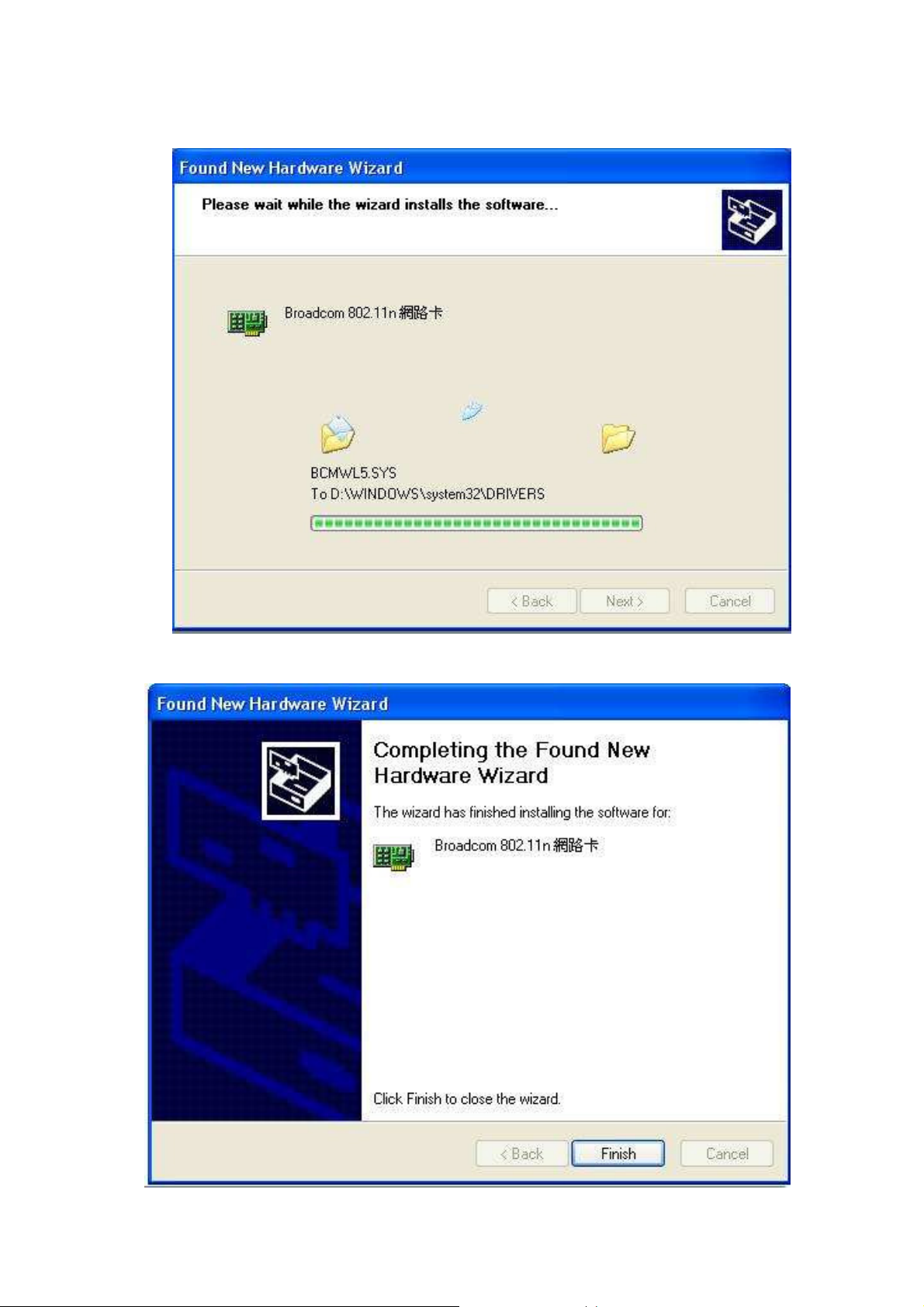
Step 4
Step 5
Page 9

 Loading...