

Page 1

Netgear CG814W Wireless Cable Modem Gateway
Netgear CG814W
Wireless Cable Modem Gateway
Quick Guide
COPYRIGHT & TRADEMARKS
Copyright 2002 Netgear, All Rights Reserved. Microsoft,
Windows, and the Windows logo are registered trademarks
of Microsoft Corporation. All other trademarks and brand
names are the property of their respective proprietors.
FCC STATEMENT
The Netgear CG814W has been tested and complies with the
specifications for a Class B digital device, pursuant to Part 15
of the FCC Rules. These limits are designed to provide
reasonable protection against harmful interface in a
residential installation. This equipment generates, uses, and
can radio frequency energy and, if not installed and used
according to the instructions, may cause harmful interference
to radio communications. However, there is no guarantee
that interference will not occur in a particular installation. If
this equipment does cause harmful interference to radio or
television reception, which is found by turning the equipment
off and on, the user is encouraged to try to correct the
interference by one or more of the following measure:
• Reorient or relocate the receiving antenna
• Increase the separation between the equipment of devices
• Connect the equipment to an outlet other than the receiver
• Consult a dealer or an experienced radio/TV technician for
assistance
0
Page 2

Netgear CG814W Wireless Cable Modem Gateway
Table of Contents
1
Page 3

Netgear CG814W Wireless Cable Modem Gateway
Chapter 1: Introduction
Overview
Thank you for purchasing the Netgear CG814W Wireless Cable Modem
Gateway. The Netgear CG814W provides the ideal solution for connecting
your wireless network to a high-speed broadband Internet connection and a
10/100 Fast Ethernet backbone. Configurable as a DHCP server for your
existing network, the Netgear CG814W acts as the only externally recognized
Internet gateway on your local area network (LAN) and serve as an Internet
NAT firewall against unwanted outside intruders. The Netgear CG814W can
also be configured to filter internal users’ access to the Internet.
A typical gateway relies on a hub or a switch to share its Internet connection,
but the Netgear CG814W channels this connection through the blazing, full
duplex of its built-in 10/100 4-Port Switch. This cutting-edge combination of
wireless router and switch technology eliminates the need to buy an additional
hub or switch and extends the range of your wireless network. Now your entire
wireless network can enjoy blazing broadband Internet connections supported
by its robust switched backbone. With the dual-function speed and power of
the Netgear CG814W, your network will take off at speeds faster than you ever
imagined possible.
Software Features
DOCSIS Features
Cable Modem (CM) is 1.0 and 1.1 upgradeable
Concatenation, Fragmentation, Payload Header suppression, IGMP
and BPI and BPI Plus are supported features for DOCSIS 1.1
4/16/32/64/128/256/512/1024 QAM Downstream Receiver
2/4/8/16/32/64/128/256 QAM Advanced TDMA Upstream Transmitter
2
Both IP and LLC filters are supported
Sixteen (16) destination address filters and 256 multicast/unicast DA
filters
Sixteen (16) independent upstream queues for multiple QoS support
Page 4

USB Features
OS (Win2K, XP, WinME) supported for USB interface
Wireless Features
Supports at least one beacon/DTIM interval of within the range
Netgear CG814W Wireless Cable Modem Gateway
20-1000
Supports reception of fragmented packets
Supports reception of RTS and generation of CTS
κμ
Firewall Features
Stateful Packet Inspection against both Denial of Service and
Distributed Denial of Service attacks and will protect against the
following:
Reassembly attacks
SYN Attack (SYN Flood)
ICMP Flood
Ping of Death Attack
Tear Drop Attack
IP Spoofing Attack
LAND Attack
Jolt
s
Winnuke Attack (Netbios out-of-bound)
OverDrop
BONK, BOINK
Blind Spoofing
Echo/Chargen
Storm
Smurf Attack
Mime Flood
De-Militarized Zone (DMZ) which allows a computer on the LAN to
expose all of its ports to the WAN that are not otherwise filtered
Logged Events which all security incidents will be logged
Keyword blocking is based on keywords in a URL and can be
specified by the user
3
Page 5

Netgear CG814W Wireless Cable Modem Gateway
NAT Requirements
The implementation of NAT must allow for specific port redirection. Listed
below are applications supported.
FTP
IRC
H.323
Quake
Blizzard games
Chat ALG
Real Audio/Video
CUSEEME
Netmeeting
MS Games but not with game zone
DIABOLO II
Activision Games
PCAnywhere
SSL
NNTP
Port Forwarding, incoming traffic that is not part of an existing
connection will be dropped unless the user specifies forwarding of the
server to a host on the LAN
Virtual Private Network (VPN) Feature
Having the ability to enable or disable PPTP and IPSec pass through
Minimum Requirements
One RJ-45 Broadband Internet connection, with a Cable Modem
One PC with an installed 10Mbps, 100Mbps, or 10/100 Mbps Ethernet
card (optional)
TCP/IP network protocol for each PC
UTP network cable with RJ-45 connector
Microsoft Internet Explorer 4.0 or later, or Netscape Navigator 4.0 or later.
(5.0 and 4.7, respectively, are strongly recommended.)
Windows 95, 98, Millennium, NT 4.0, 2000 or XP
Package Contents
4
Page 6

Netgear CG814W Wireless Cable Modem Gateway
{1} Cable Modem
{1} AC Power adapter
{1} CAT.5 Ethernet cable {RJ-45}
{1} USB cable
{1} User’s Manual
5
Page 7
Netgear CG814W Wireless Cable Modem Gateway
Chapter 2: Using the Netgear CG814W
All interface and status LEDs are provided on the front panel. The power
connectors, signal connectors, and Restore Factory Defaults/Reboot button
are on the rear panel.
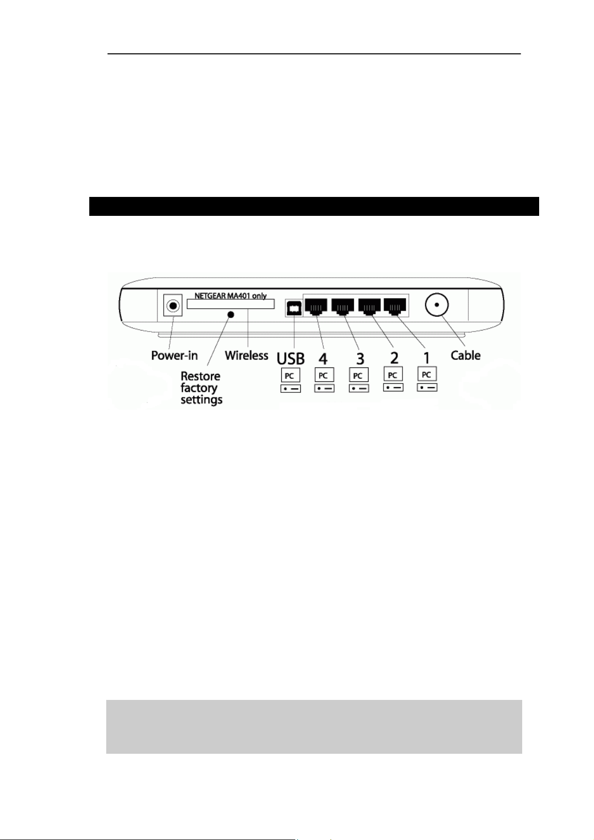
The Netgear CG814W’s Rear Panel
The rear panel of the Netgear CG814W is where all of the device’s
connections are made.
Power-in The Power Port is where you will connect the included
AC Power adapter.
USB The USB Port. You can connect the Gateway to PC
using USB line.
1~4 These four LAN (Local Area Network) ports are where
you will connect networked devices, such as PCs, print
servers and any other Ethernet devices you want to put
on your network. If Port 4 is being used, the Uplink Port
will not work.
Cable The Cable Line Port (Coaxial Copper).
Wireless The Wireless Network PC Card is inserted into this slot
to enable the wireless features. This slot is not hot
swappable.
The Restore factory settings Button
Briefly pressing the Reset Button will clear all of the Gateway’s data and
restore the factory defaults. This should be done only if you are experiencing
6
Page 8
Netgear CG814W Wireless Cable Modem Gateway
heavy routing problems, and only after you have exhausted all of the other
troubleshooting options. By resetting the Gateway, you run the risk of creating
conflicts between your PCs’ actual IP Addresses and what the Gateway thinks
their IP Addresses should be. You may be forced to reboot the entire
system(s).
If your Gateway locks up, simply power it down for 5 seconds by removing the
power cable from the Gateway’s Power Port. Leaving the power off for too
long could result in the loss of network connections.
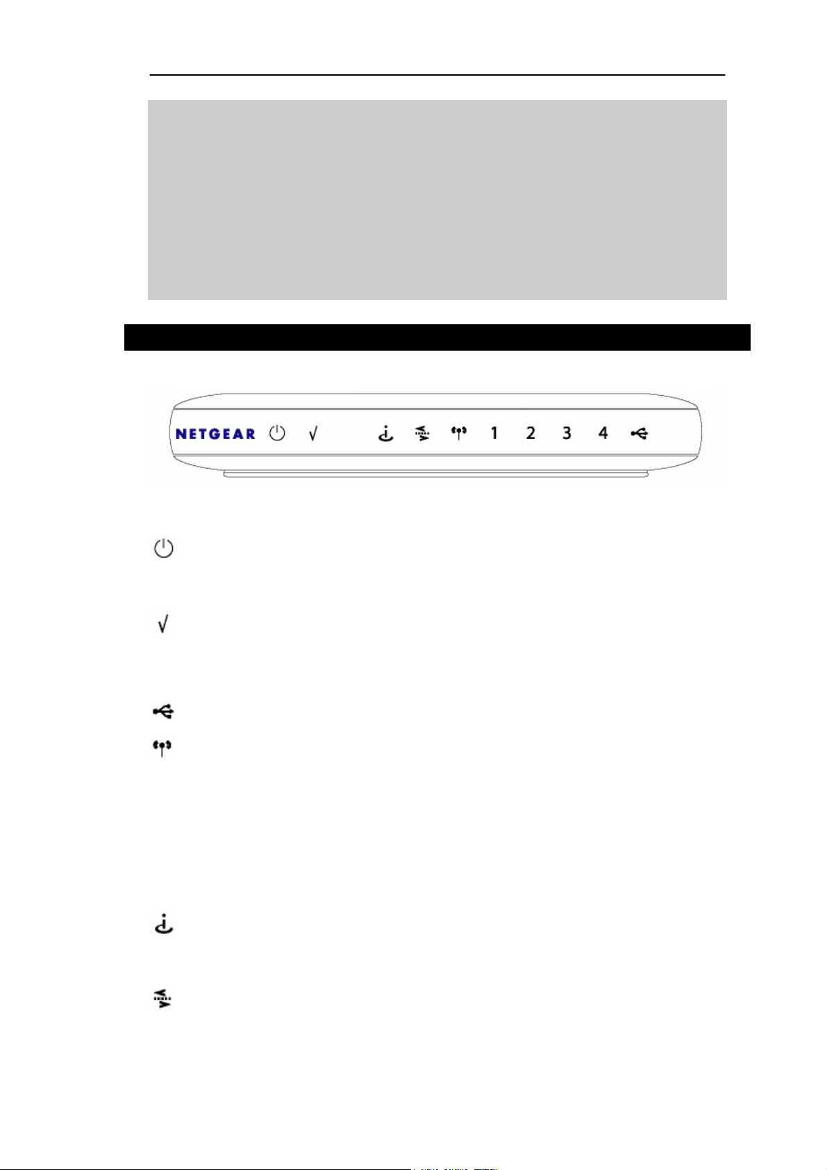
The Netgear CG814W’s Front Panel
Green. The power LED illuminates when the device is powered
on.
Red. The Diag LED illuminates when the device goes through its
self-diagnosis mode during boot-up and restart. It will turn off
upon successful completion of the diagnosis.
Green. Blinking when the USB port is activity
Green. The WLAN LED illuminates when the Wireless PC card
slide-in and activity.
1~4 Green. When a successful 100Mbps connection is made through
the corresponding port.
Yellow. When a successful 10Mbps connection is made through
the corresponding port.
Green. Steady on when cable is registered and ready to transfer
data.
Green. Blinking when user data going through the cable modem
to PC present.
7
Page 9

Netgear CG814W Wireless Cable Modem Gateway
Chapter 3: Connect the Gateway
Overview
Unlike a simple hub or switch, the Gateway’s setup consists of more than
simply plugging hardware together. You will have to configure your networked
PCs to accept the IP addresses that the Gateway assigns them (if applicable),
and you will also have to configure the Gateway with setting(s) provided by
your Internet Service Provider (ISP).
The installation technician from your ISP should have left the setup
information with you after installing your broadband connection. If not, you can
call your ISP to request the data.
Once you have the setup information you need for your specific type of
Internet connection, you can begin installation and setup of the Gateway.
Connecting Your Hardware Together and Booting Up
1. Before you begin, make sure that all of you hardware is powered off,
including the Gateway, PCs, hubs, and switches.
2. Connect one end of an Ethernet cable to one of the LAN ports (labeled 1, 2,
3, or 4) on the back of the Gateway and the other end to a standard port on
a network device, e.g., a PC, print server, hub, or switch. Repeat the above
step to connect more PCs or network devices to the Gateway.
3. Connect the cable from your ISP to the Cable port on the Gateway’s back
panel.
4. Connect the power-supply cable to the Power port on the rear of the
Gateway, then plug the supplied AC power cable into a power outlet and
power on the Netgear CG814W.
• The Power LED on the front panel will light up green as soon as the
power adapter is connected properly.
• The Diag LED will light up red for a few seconds when the Gateway
8
Page 10

Netgear CG814W Wireless Cable Modem Gateway
goes through its self-diagnostic test. The LED will turn off when the
self-test is complete.
5. Power on the network devices that connected to the Netgear CG814W.
The Hardware Installation is complete. Continue to the next page to
configure your PCs with Netgear CG814W.
9
Page 11

Netgear CG814W Wireless Cable Modem Gateway
Chapter 4: Configure Your PCs
Overview
The instructions in this chapter will help you configure each of your computer
to be able to communicate with the Gateway.
To do this, you need to configure your PC’s network settings to obtain an IP (or
TCP/IP) address automatically (called DHCP). Computers use IP addresses to
communicate with each other across a network or the Internet.
Find out which operating system your computer is running, such as Windows
95, 98, Millennium, NT 4.0, 2000, or XP. You will need to know which operating
system your computer is running. You can find out by clicking the Start button
and then going to the Settings option. Then click Control Panel, and then
double-click the System icon. If your Start menu doesn’t have a Settings
option, you’re running Windows XP. Click the Cancel button when done.
You may need to do this for each computer you are connecting to the
Gateway.
Important: These instructions apply only to Windows 95, 98, Millennium, 2000,
or XP machines. For TCP/IP setup under Windows NT, see your Windows
manual. By default Windows 98, 2000, Me, and XP has TCP/IP installed and
set to obtain an IP address automatically.
The next few pages tell you, step by step, how to configure your network
settings based on the type of Windows operating system you are using. Make
sure that an Ethernet card or adapter has been successfully installed in each
PC you will configure.
Configuring Windows 95, 98, and Millennium PCs
1. Go to the Network screen by click the Start button. Click Settings and then
Control Panel. From there, double-click the Network icon.
2. On the Configuration tab, select the TCP/IP line for the applicable Ethernet
10
Page 12
Netgear CG814W Wireless Cable Modem Gateway
adapter. Do not choose a TCP/IP entry whose name mentions DUN,
PPPoE, VPN, or AOL. If the work TCP/IP appears by itself, select that line.
(If there is no TCP/IP line listed, refer to “Appendix C: Installing the TCP/IP
Protocol.) Click the Properties button.
3. Click the IP Address tab. Select Obtain an IP address automatically.
11
Page 13

Netgear CG814W Wireless Cable Modem Gateway
4. Now click the Gateway tab to ensure that the Installed Gateway field is left
blank. Click the OK button.
5. Click the OK button again. Windows may ask you for the original Windows
installation disk or additional files. Supply them by pointing to the correct
file location, e.g., D:\win98, D:\win9x, c:\windows\options\cabs, etc. (if “D”
is the letter of your CD-ROM drive).
6. Windows may ask you to restart your PC. Click the Yes button. If Windows
does not ask you to restart, restart your computer anyway.
Configuring Windows 2000 PCs
1. Go to the Network screen by clicking the Start button. Click Settings and
then Control Panel. From there, double-click the Network and Dial-up
Connections icon.
2. Select the Local Area Connection icon for the applicable Ethernet
12
Page 14

Netgear CG814W Wireless Cable Modem Gateway
adapter (usually it is the first Local Area Connection listed). Double-click
the Local Area Connection. Click the Properties button.
3. Select Internet Protocol (TCP/IP), and click the Properties button.
4. Select Obtain an IP address automatically. Once the new window
appears, click the OK button. Click the OK button again to complete the
PC configuration.
5. Restart your computer.
Configuring Windows XP PCs
The following instructions assume you are running Windows XP with the
default interface. If you are using the Classic interface (where the icons and
menus look like previous Windows versions), please follow the instructions for
Windows 2000.
1. Go to the Network screen by clicking the Start button and then Control
Panel. From there, double-click the Network Internet Connections icon
and then the Network Connections icon.
2. Select the Local Area Connection icon for the applicable Ethernet
adapter (usually it is the first Local Area Connection listed). Double-click
the Local Area Connection. Click the Properties button.
3. Select Internet Protocol (TCP/IP), and click the Properties button.
4. Select Obtain an IP address automatically. Once the new window
appears, click the OK button. Click the OK button again (or the Close
button if any settings were changed) to complete the PC configuration.
5. Restart your computer.
13
Page 15

Netgear CG814W Wireless Cable Modem Gateway
Appendix A: Troubleshooting
Common Problems and Solutions
This section provides possible solutions to problems regarding the installation
and operation of the Netgear CG814W. If your situation is described here, the
problem should be solved by applying the corresponding solution. If you can’t
find an answer here, please contact with your local dealer.
1. I need to set a static IP address on a PC.
The Gateway, by default, assigns an IP address range of 192.168.100.10 to
192.168.100.41 using the DHCP server on the Gateway. To set a static IP
address, you can only use the ranges 192.168.100.2 to 192.168.100.9 and
192.168.100.42 to 192.168.100.254. Each PC or network device that uses
TCP/IP must have a unique address to identify itself in a network. If the IP
address is not unique to a network, Windows will generate IP conflict error
message. You can assign a static IP address to a PC by performing the
following steps:
For Windows 95, 98, and Me:
A. Click Start, Settings, and Control Panel. Double-click Network.
B. In The following network components are installed box, select the
TCP/IP->associated with your Ethernet adapter. If you only have one
Ethernet adapter installed, you will only see one TCP/IP line with no
association to an Ethernet adapter. Highlight it and click the Properties
button.
C. In the TCP/IP properties window, select the IP address tab, and select
Specify an IP address. Enter a unique IP address that is not used by any
other computer on the network connected to the Gateway. You can only
use an IP address in the ranges 192.168.100.2 to 192.168.100.9 and
192.168.100.42 to 192.168.100.254. Make sure that each IP address is
unique for each PC or network device.
D. Click the Gateway tab, and in the New Gateway prompt, enter
192.168.100.1, which is the default IP address of the Gateway. Click the
Add button to accept the entry.
E. Click the DNS tab, and make sure the DNS Enabled option is selected.
14
Page 16

Netgear CG814W Wireless Cable Modem Gateway
Enter the Host and Domain names (e.g., Johnson for Host and home for
Domain). Enter the DNS entry provided by your ISP. If your ISP has not
provided the DNS IP address, contact your ISP to get that information or
go to its website for the information.
F. Click the OK button in the TCP/IP properties window, and click Close or
the OK button for the Network window.
G. Restart the computer when asked.
For Windows 2000:
A. Click Start, Settings, and Control Panel. Double-click Network and
Dial-Up Connections.
B. Right-click the Local Area Connection that is associated with the Ethernet
adapter you are using, and select the Properties option.
C. In the Components checked are used by this connection box, highlight
Internet Protocol (TCP/IP), and click the Properties button. Select Use
the following IP address option.
D. Enter a unique IP address that is not used by any other computer on the
network connected to the Gateway. You can only use an IP address in the
ranges 192.168.100.2 to 192.168.100.9 and 192.168.100.42 to
192.168.100.254.
E. Enter the Subnet Mask, 255.255.255.0.
F. Enter the Default Gateway, 192.168.100.1 (Gateway’s default IP address).
G. Toward the bottom of the window, select Use the following DNS server
address, and enter the Preferred DNS server and Alternative DNS
server (provided by your ISP). Contact your ISP or go on its website to find
the information.
H. Click the OK button in the Internet Protocol (TCP/IP) Properties window,
and click the OK button in the Local Area Connection Properties
window.
I. Restart the computer if asked.
For Windows NT 4.0:
A. Click Start, Settings, and Control Panel. Double-click Network icon.
B. Click the Protocol tab, and double-click TCP/IP Protocol.
C. When the window appears, make sure you have selected the correct
Adapter for your Ethernet adapter.
15
Page 17

Netgear CG814W Wireless Cable Modem Gateway
D. Select Specify an IP address, and enter a unique IP address that is not
used by any other computer on the network connected to the Gateway. You
can only use an IP address in the ranges 192.168.100.2 to 192.168.100.9
and 192.168.100.42 to 192.168.100.254.
E. Enter the Subnet Mask, 255.255.255.0.
F. Enter the Default Gateway, 192.168.100.1 (Gateway’s default IP address).
G. Click the DNS tab, and enter the Host and Domain names (e.g., Johnson
for Host and home for Domain). Under DNS Service Search Order, click
the Add button. Enter the DNS IP address in the DNS Server field, and
click the Add button. Repeat this action for all DNS IP addresses given by
your ISP.
H. Click the OK button in the TCP/IP Protocol Properties window, and click
the Close button in the Network window.
I. Restart the computer if asked.
For Windows XP:
The following instructions assume you are running Windows XP with the
default interface. If you are using the Classic interface (where the icons and
menus look like previous Windows versions), please follow the instruction for
Windows 2000.
A. Click Start and Control Panel.
B. Click the Network and Internet Connections icon and then the Network
Connections icon.
C. Right-click the Local Area Connection that is associated with the Ethernet
adapter you are using, and select the Properties option.
D. In the This connection uses the following items box, highlight Internet
Protocol (TCP/IP). Click the Properties button.
E. Click the use the following IP address radio button. Enter a unique IP
address that is not used by any other computer on the network connected
to the Gateway. You can only use an IP address in the ranges
192.168.100.2 to 192.168.100.9 and 192.168.100.42 to 192.168.100.254.
F. Enter the Subnet Mask, 255.255.255.0.
G. Enter the Default Gateway, 192.168.100.1 (Gateway’s default IP address).
H. Toward the bottom of the window, select Use the following DNS server
addresses, and enter the Preferred DNS server and Alternative DNS
server (provided by your ISP). Contact your ISP or go on its website to find
16
Page 18

Netgear CG814W Wireless Cable Modem Gateway
the information.
I. Click the OK button in the Internet Protocol (TCP/IP) Properties window.
Click the OK button in the Local Area Connection Properties window.
2. I want to test my Internet connection.
A. Check your TCP/IP settings.
For Windows 95, 98, and ME:
Refer to the “Configuring Your PCs to Connect to the Netgear CG814W”
section of “Connecting the Netgear CG814W to Your Network”. Make sure
Obtain IP address automatically is selected in the settings.
For Windows 2000:
• Click Start, Settings, and Control Panel. Double-click Network and
Dial-Up Connections.
• Right-click the Local Area Connection that is associated with the
Ethernet adapter you are using, and select the Properties option.
• In the Components checked are used by this connection box, highlight
Internet Properties (TCP/IP), and click the Properties button. Make
sure that Obtain an IP address automatically and Obtain DNS
server address automatically are selected.
• Click the OK button in the Internet Protocol (TCP/IP) Properties window,
and click the OK button in the Local Area Connection Properties
window.
• Restart the computer if asked.
For Windows XP:
The following instructions assume you are running Windows XP with the
default interface. If you are using the Classic interface (where the icons
and menus look like previous Windows versions), please follow the
instructions for Windows 2000.
• Click Start and Control Panel.
• Click the Network and Internet Connections icon and then the
Network Connections icon.
• Right-click the Local Area Connection that is associated with the
Ethernet adapter you are using, and select the Properties option.
• In the This connection uses the following items box, highlight Internet
17
Page 19

Netgear CG814W Wireless Cable Modem Gateway
Protocol (TCP/IP), and click the Properties button. Make sure that
Obtain an IP address automatically and Obtain DNS server
address automatically are selected.
• Click the OK button in the Internet Protocol (TCP/IP) Properties window,
and click the OK button in the Local Area Connection Properties
window.
• Restart the computer if asked.
For Windows NT 4.0:
• Click Start, Settings, and Control Panel. Double-click the Network
icon.
• Click the Protocol tab, and double-click on TCP/IP Protocol.
• When the window appears, make sure you have selected the correct
Adapter for your Ethernet adapter and set it for Obtain an IP address
from a DHCP server.
• Click the OK button in the TCP/IP Protocol Properties window, and click
the Close button in the Network window.
• Restart the computer if asked.
B. Open a command prompt.
• For Windows 95, 98, and Me, please click Start and Run. In the Open
field, type in command. Press the Enter key or click the OK button.
• For Windows NT, 2000, and XP, please click Start and Run. In the
Open field , type cmd. Press the Enter key or click the OK button.
C. In the command prompt, type ping 192.168.100.1 and press the Enter key.
• If you get a reply, the computer is communicating with the Gateway.
• If you do NOT get a reply, please check the cable, and make sure
Obtain an IP address automatically is selected in the TCP/IP settings
for your Ethernet adapter.
D. In the command prompt, type ping followed by your WAN IP address and
press the Enter key. The WAN IP Address can be found in the web
interface of the Gateway. For example, if your WAN IP address is 1.2.3.4,
you would enter ping 1.2.3.4 and press the Enter key.
• If you get a reply, the computer is connected to the Gateway.
• If you do NOT get a reply, try the ping command from a different
computer to verify that your original computer is not the cause of the
18
Page 20

Netgear CG814W Wireless Cable Modem Gateway
problem.
E. In the command prompt, type ping www.yahoo.com and press the Enter
key.
• If you get a reply, the computer is connected the Internet. If you can not
open a web page, try the ping command from a different computer to
verify that your original computer is not the cause of the problem.
• If you do NOT get a reply, there may be a problem with the connection.
Try the ping command from a different computer to verify that your
original computer is not the cause of the problem.
3. I am not getting an IP address on the WAN with my Internet
connection.
A. Refer to “Problem #2, I want to test my Internet connection” to verify
that you have connectivity.
B. Make sure you are using the right WAN settings. Contact your ISP to
see if your WAN connection type is DHCP, Static IP Address.
C. Make sure you have the right cable. Check to see if the Cable Modem
column has a solidly lit Link LED.
D. Make sure the cable connecting from your ISP is connected to the
Gateway’s Cable port. Verify that the Status page of the Gateway’s web
interface shows a valid IP address from your ISP.
E. Turn off the computer, Gateway. Wait 30 seconds, and then turn on the
Gateway and computer. Check the Status tab of the Gateway’s
web-based utility to see if you get an IP address.
4. I am not able to access the Gateway’s web interface Configuration
page.
A. Refer to “Problem #2, I want to test my Internet connection” to verify
that your computer is properly connected to the Gateway.
B. Refer to “Appendix D: Finding the MAC Address and IP address for
Your Ethernet Adapter” to verify that your computer has an IP Address,
Subnet Mask, Gateway, and DNS.
C. Set a static IP address on your system; refer to “Problem #1, I need to
set a static IP address”.
D. Refer to “Problem #9: I need to remove the proxy settings or the dial-up
pop-up windows (for PPPoE users).”
19
Page 21

Netgear CG814W Wireless Cable Modem Gateway
5. I need to set up a server behind my Gateway.
To use a server like a web, ftp, or mail server, you need to know the respective
port numbers they are using. For example, port 80 (HTTP) is used for web,
port 21 (FTP) is used for FTP, and port 25 (SMTP outgoing) and port 110
(POP3 incoming) are used for the mail server. You can get more information
by viewing the documentation provided with the server you installed. Follow
these steps to set up port forwarding through the Gateway’s web-based utility.
We will be setting up web, ftp, and mail servers.
A. Access the Gateway’s web-based utility by going to http://192.168.100.1
or IP address of the Gateway. Go to the Advanced => Forwarding tab.
B. Enter the Port range of the service you are using. For example, if you have
a web server, you would enter the range 80 to 80.
C. Check the protocol you will be using, TCP, UDP or Both.
D. Enter the IP address of the PC or network device that you want the port
server to go to. For example, if the web server’s Ethernet adapter IP
address is 192.168.100.2, you would enter 2 in the field provided. The 0 is
to disable port service.
When you have completed the configuration, click the Apply button.
6. I need to set up online game hosting or use other Internet
applications.
If you want to play online games or use Internet applications, most will work
without doing any port forwarding or DMZ hosting. There may be cases when
you want to host an online game or Internet application. This would require
you to set up the Gateway to deliver incoming packets or data to a specific
computer. This also applies to the Internet applications you are using. The
best way to get the information on what port services to use is to go to the
website of the online game or application you want to use. Follow these steps
to set up online game hosting or use a certain Internet application:
A. Access the Gateway’s web-based utility by going to http://192.168.100.1
or IP address of the Gateway. Go to the Advanced => Forwarding tab.
B. Enter the Port range of the service you are using. For example, if you want
to host Unreal Tournament (UT), you would enter the range 7777 to 27900.
C. Check the protocol you will be using, TCP, UDP or Both.
20
Page 22

Netgear CG814W Wireless Cable Modem Gateway
D. Enter the IP address of the PC or network device that you want the port
server to go to. For example, if the web server’s Ethernet adapter IP
address is 192.168.100.2, you would enter 2 in the field provided. The 0 is
to disable port service.
When you have completed the configuration, click the Apply button.
7. I can’t get the Internet game, server, or application to work.
If you are having difficulties getting any Internet game, server, or application to
function properly, consider exposing one PC to the Internet using DeMilitarized
Zone (DMZ) hosting. This option is available when an application requires too
many ports or when you are not sure which port services to use. Make sure
you disable all the forwarding entries if you want to successfully use DMZ
hosting, since forwarding has priority over DMZ hosting. (In other words, data
that enters the Gateway will be checked first by the forwarding settings. If the
port number that the data enters from does not have port forwarding, then the
Gateway will send the data to whichever PC or network device you set for
DMZ hosting.) Follow these steps to set DMZ hosting:
A. Access the Gateway’s web-based utility by going to http://192.168.100.1
or the IP address of the Gateway. Go to the Advanced => Forwarding
tab.
B. Disable or remove the entries you have entered for forwarding. Keep this
information in case you want to use it at a later time.
C. Click the DMZ Host tab.
D. Enter the Ethernet adapter’s IP address of the computer you want
exposed to the Internet. This will bypass the NAT firewall for that computer.
Once completed with the configuration, click the Apply button.
8. I forgot my password, or the password prompt always appears when
saving settings to the Gateway.
Reset the Gateway to factory default by pressing the Reset button for 5
seconds and then releasing it. If you are still getting prompted for a password
when saving settings, then perform the following steps:
A. Access Gateway’s web interface by going to http://192.168.100.1 or the IP
address of the Gateway. Enter the default password admin, and then go
21
Page 23

Netgear CG814W Wireless Cable Modem Gateway
to Basic => Security page.
B. Enter a different password in the Password field, and enter the same
password in the second field to confirm the password.
C. Click the Apply button.
9. I am a PPPoE user, and I need to remove the proxy settings or the
dial-up pop-up window.
If you have proxy settings, you need to disable these on your computer.
Because the Gateway is the gateway for the Internet connection, the computer
does not need any proxy settings to gain access. Please follow these
directions to verify that you do not have any proxy settings and that the
browser you use is set to connect directly to the LAN.
For Microsoft Internet Explorer 5.0 or higher:
A. Click Start, Settings, and Control Panel. Double-click Internet Options.
B. Click the Connections tab.
C. Click the LAN settings button and remove anything that is checked.
D. Click the OK button to go back to the previous screen.
E. Click the option Never dial a connection. This will remove any dial-up
pop-ups for PPPoE users.
For Netscape 4.7 or higher:
A. Start Netscape Navigator, and click Edit, Preferences, Advanced, and
Proxies.
B. Make sure you have Direct connection to the Internet selected on this
screen.
C. Close all the windows to finish.
10. To start over, I need to set the Gateway to factory default.
Hold the Reset button for up to 5 seconds and then release it. This will return
the password, forwarding, and other settings on the Gateway to the factory
default settings. In other words, the Gateway will revert to its original factory
configuration.
11. I need to use port triggering.
Port triggering looks at the outgoing port services used and will trigger the
Gateway to open a specific port, depending on which port an Internet
application uses. Follow these steps:
22
Page 24

Netgear CG814W Wireless Cable Modem Gateway
A. To connect to the Gateway, go to the web browser, and enter
http://192.168.100.1 or the IP address of the Gateway.
B. Enter the password, if asked. (The default password is admin.)
C. Click the Advanced => Port Triggering tab.
D. Enter the Trigger Range. Check with your Internet application provider for
more information on which outgoing port services it is using.
E. Enter the Ta rge t Ra nge. Check with your Internet application provider for
more information on which incoming port services are required by the
Internet application.
12. The Diag LED stays lit continuously.
• The Diag LED lights up when the device is first powered up. Meantime,
the system will boot up itself and check for proper operation. After
finishing the checking procedure, the LED turns off to show the system
is working fine. If the LED remains lit after this time, the device is not
working properly. Try to flash the firmware by assigning a static IP
address to the computer, then upgrade the firmware. Try using the
following settings, IP Address: 192.168.1.50 and Subnet Mask:
255.255.255.0. To set a static IP address, refer to “Problem #1: I need
to set a static IP address.
13. When I enter a URL or IP address, I get a time-out error or a
prompted to retry.
• Check if other PCs work. If they do, ensure that your workstation’s IP
settings are correct (IP Address, Subnet Mask, Default Gateway, and
DNS). Restart the computer that is having a problem.
• If the PCs are configured correctly, but still not working, check the
Gateway. Ensure that it is connected and ON. Connect to it and check
its settings. (If you cannot connect to it, check the LAN and power
connections.)
• If the Gateway is configured correctly, check your Internet connection to
see if it is working correctly.
• Manually configure the TCP/IP with a DNS address provided by your
ISP.
• Make sure that your browser is set to connect directly and that any
dial-up is disabled. For Internet Explorer, click Tools, Internet Options,
and the Connection tab. Make sure that Internet Explorer is set to
23
Page 25

Netgear CG814W Wireless Cable Modem Gateway
Never dial a connection. For Netscape Navigator, click Edit,
Preferences, Advanced, and Proxy. Make sure that Netscape
Navigator is set to Direct connection to the Internet.
14. The Full/Col LED keeps flickering continuously.
• Check the Category 5 Ethernet cable and it RJ-45 connectors.
• There may be interference with other network devices. Try removing
other PCs or network devices to see if the problem persists. Eliminate
each network device one at a time to determine the cause.
24
Page 26

Netgear CG814W Wireless Cable Modem Gateway
Frequently Asked Questions
What is the maximum number of IP addresses that the Gateway will
support? The Gateway will support up to 253 IP addresses.
Is IPSec Pass-Through supported by the Gateway? Yes, it is a build-in
feature that the Gateway automatically enables.
Does the Gateway support IPX or AppleTalk? No. TCP/IP is the only
protocol standard for the Internet and has become the global standard for
communications. IPX, a NetWare communications protocol used only to route
messages from one node to another, and AppleTalk, a communications
protocol used on Apple and Macintosh networks, can be used for LAN to LAN
connections, but those protocols cannot connect from WAN to LAN.
What is Network Address Translation and what is it used for? Network
Address Translation (NAT) translates multiple IP addresses on the private LAN
to one public address that is sent out to the Internet. This adds a level of
security since the address of a PC connected to the private LAN is never
transmitted on the Internet. Furthermore, NAT allows the Gateway to be used
with low cost Internet accounts, when only one TCP/IP address is provided by
the ISP. The user may have many private addresses behind this single
address provided by the ISP.
Does the Gateway support any operating system other than Windows 95,
Windows 98, Windows 2000, Windows NT, or Windows XP? Yes, but we
does not, at this time, provide technical support for setup, configuration or
troubleshooting of any non-Windows operating systems.
I set up an Unreal Tournament Server, but others on the LAN cannot join.
What do I need to do? If you have a dedicated Unreal Tournament server
running, you need to create a static IP for each of the LAN computers and
forward ports 7777, 7778, 7779, 7780, 7781, and 27900 to the IP address of
the server. You can also use a port forwarding range of 7777~27900. If you
want to use the UT Server Admin, forward another port (8080 usually works
well but is used for remote admin. You may have to disable this.), and then in
the [Uweb.WebServer] section of the server.ini file, set the ListenPort to 8080
25
Page 27

Netgear CG814W Wireless Cable Modem Gateway
(to match the mapped port above) and ServerName to the IP assigned to the
Gateway from your ISP.
Can multiple gamers on the LAN get on one game server and play
simultaneously with just one public IP address? It depends on which
network game or what kind of game server you are using. For example, Unreal
Tournament supports multi-login with one public IP.
How do I get Half-Life: Team Fortress to work with the Gateway? The
default client port for Half-Life is 27005. The computers on your LAN need to
have “+clientport 2700x” added to the HL shortcut command line; the x would
be 6, 7, 8, and on up. This lets multiple computers connect to the same server.
One problem: Version 1.0.1.6 won’t let multiple computers with the same CD
key connect at the same time, even if on the same LAN (not a problem with
1.0.1.3). As far as hosting games, the HL server does not need to be in the
DMZ. Just forward port 207015 to the local IP address of the server computer.
How can I block corrupted FTP downloads? If you are experiencing
corrupted files when you download a file with your FTP client, try using
another FTP program.
The web page hangs; downloads are corrupt, or nothing but junk
characters are being displayed on the screen. What do I need to do?
Force your Ethernet adapter to 10Mbps or half duplex mode, and turn off the
“Auto-negotiate” feature of your Ethernet adapter as a temporary measure.
(Please look at the Network Control Panel in your Ethernet adapter’s
Advanced Properties tab.) Make sure that your proxy setting is disabled in the
browser.
Will the Gateway function in a Macintosh environment? Yes, but the
Gateway’s setup pages are accessible only through Internet Explorer 4.0 or
Netscape Navigator 4.0 or higher for Macintosh.
I am not able to get the web configuration screen for the Gateway. What
can I do? You may have to remove the proxy settings on your Internet browser,
e.g., Netscape Navigator or Internet Explorer. Or remove the dial-up settings
on your browser. Check with your browser documentation, and make sure that
your browser is set to connect directly and that any dial-up is disabled. For
26
Page 28

Netgear CG814W Wireless Cable Modem Gateway
Internet Explorer, click Tools, Internet Options, and then the Connection tab.
Make sure that Internet Explorer is set to Never dial a connection. For
Netscape Navigator, click Edit, Preferences, Advanced, and Proxy. Make
sure that Netscape Navigator is set to Direct connection to the Internet.
What is DMZ hosting? Demilitarized Zone (DMZ) allows one IP address
(computer) to be exposed to the Internet. Some applications require multiple
TCP/IP ports to be open. It is recommended that you set your computer with a
static IP if you want to use DMZ Hosting.
If DMZ Hosting is used, does the exposed user share the public IP with
the Gateway? No.
Is the Gateway cross-platform compatible? Any platform that supports
Ethernet and TCP/IP is compatible with the Gateway.
How many ports can be simultaneously forwarded? Theoretically, the
Gateway can establish 520 sessions at the same time, but you can only
forward 10 ranges of ports.
What are the advanced features of the Gateway? The Gateway’s advanced
features include Filters, Forwarding, DMZ Hosting.
How can I check whether I have static or DHCP IP Addresses? Consult
your ISP to obtain this information.
27
Page 29

Netgear CG814W Wireless Cable Modem Gateway
Appendix B: Glossary
10BaseT – An Ethernet standard that uses twisted wire pairs.
100BaseTX – IEEE physical layer specification for 100 Mbps over two pairs of
Category 5 UTP or STP wire.
Adapter – Printed circuit board that plugs into a PC to add to capabilities or
connectivity to a PC. In a network environment, a network interface card (NIC)
is the typical adapter that allows the PC or server to connect to the intranet
and/or Internet.
Bridge – A device that interconnects different networks together.
Browser – A browser is an application program that provides a way to look at
and internet with all the information on the World Wide Web or PC. The word
“browser” seems to have originated prior to the Web as a generic term for user
interfaces that let you browse text files online.
CAT 5 – ANSI/EIA (American National Standards Institute/Electronic
Industries Association) Standard 568 is one of several standards that specify
“categories” (the singular is commonly referred to as “CAT”) of twisted pair
cabling systems (wires, junctions, and connectors) in terms of the data rates
that they can sustain. CAT5 cable has a maximum throughput of 100 Mbps
and is usually utilized for 100BaseTX networks.
Default Gateway – The routing device used to forward all traffic that is not
addressed to a station within the local subnet.
DHCP (Dynamic Host Configuration Protocol) – A protocol that lets network
administrators manage centrally and automate the assignment of Internet
Protocol (IP) addresses in an organization’s network. Using the Internet’s set
of protocol (TCP/IP), each machine that can connect to the Internet needs a
unique IP address. When an organization sets up its computer users with a
connection to the Internet, an IP address must be assigned to each machine.
Without DHCP, the IP address must be entered manually at each computer
and, if computers move to another location in another part of the network, a
28
Page 30

Netgear CG814W Wireless Cable Modem Gateway
new IP address must be entered. DHCP lets a network administrator
supervise and distribute IP addresses from a central point and automatically
sends a new IP address when a computer is plugged into a different place in
the network.
DHCP uses the concept of a “lease” or amount of time that a given IP address
will be valid for a computer. The lease time ca vary depending on how long a
user is likely to require the Internet connection at a particular location. It’s
especially useful in education and other environments where users change
frequently. Using very short leases, DHCP can dynamically reconfigure
networks in which there are more computers than there are available IP
addresses.
DHCP supports static addresses for computers containing Web servers that
need a permanent IP address.
DMZ – A DMZ (DeMilitarized Zone) is a computer host or small network
inserted as a “neutral zone” between a company’s private network and the
outside public network. It prevents outside users from getting direct access to
a server that has company data.
DNS – The domain name system (DNS) is the way that Internet domain name
are located and translated into Internet Protocol (IP) addresses. A domain
name is a meaningful and easy-to-remember “handle” for an Internet address.
Domain – A sub-network comprised of a group of clients and servers under
the control of one security database. Dividing LANs into domains improves
performance and security.
DSSS – Also known as “Direct Sequence Speed Spectrum”, this is a variety of
radio transmission methods that continuously change frequencies or signal
patterns. Direct sequence speed spectrum (DSSS), which is used in CDMA,
multiples the data bits by a very fast pseudo-random bit pattern (PN sequence)
that “spreads” the data into a large coded stream that takes the full bandwidth
of the channel.
Dynamic IP Address – An IP address that is automatically assigned to a
client station in a TCP/IP network, typically by a DHCP server. Network
29
Page 31

Netgear CG814W Wireless Cable Modem Gateway
devices that serve multiple users, such as servers and printers, are usually
assigned static IP address.
Ethernet – IEEE standard network protocol that specifies how data is placed
on and retrieved from a common transmission medium. Has a transfer rate of
10 Mbps. Forms the underlying transport vehicle used by several upper-level
protocols, including TCP/IP and XNS.
Firewall – A firewall is a set of related programs, located at a network gateway
server, that protects the resources of a network from users from other
networks. (The term also implies the security policy that is used with the
programs.) An enterprise with an intranet that allows its workers access to the
wider Internet installs a firewall to prevent outsiders from accessing its own
private data resources and for controlling what outside resources to which its
own users have access.
Basically, a firewall, working closely with a Gateway program, examines each
network packet to determine whether to forward it toward its destination.
Firmware – Programming that is inserted into programmable read-only
memory (programmable read-only memory), thus becoming a permanent part
of a computing device.
FTP (File Transfer Protocol) – A protocol used to transfer files over a TCP/IP
network (Internet, UNIX, etc.). For example, after developing the HTML pages
for a website on a local machine, they are typically uploaded to the Web server
using FTP.
FTP includes functions to log onto the network, list directories, and copy files.
It can also convert between the ASCII and EBCDIC character codes. FTP
operations can be performed by typing commands at a command prompt or
via an FTP utility running under a graphical interface such as Windows, FTP
transfers can also be initiated from within a Web browser by entering the URL
preceded with ftp://..
Unlike e-mail programs in which graphics and program files have to be
“attached,” FTP is designed to handle binary files directly and does not add
the overhead of encoding and decoding the data.
30
Page 32

Netgear CG814W Wireless Cable Modem Gateway
Gateway – A device that interconnects networks with different, incompatible
communications protocols.
Hub – The device that serves as the central location for attaching wires from
workstations. Can be passive, where there is no amplification of the signals; or
active, where the hubs are used like repeaters to provide an extension of the
cable that connects to a workstation.
IEEE – The Institute of Electrical and Electronics Engineers. The IEEE
describes itself as “the world’s largest technical professional society –
promoting the development and application of electro-technology and allied
sciences for the benefit of humanity, the advancement of the profession, and
the well-being of our members.”
The IEEE fosters the development of standards that often become national
and international standards. The organization publishes a number of journals,
has many local chapters, and several large societies in special areas, such as
the IEEE Computer Society.
IP Address – In the most widely installed level of the IP (Internet Protocol)
today, an IP address is a 32-binary digit number that identifies each sender or
receiver of information that is sent in packet across the Internet. When you
request an HTML page or send e-mail, the Internet Protocol part of TCP/IP
includes your IP address in the message (actually in each of the packets if
more than one is required) and sends it to the IP address that is obtained by
looking up the domain name in the Uniform Resource Locator you requested
or in the e-mail address you’re sending a note to. At the other end, the
recipient can see the IP address of the Web page requestor or the e-mail
sender and can respond by sending another message using the IP address it
received.
IPSec – IPSec (Internet Protocol Security) is a developing standard for
security at the network or packet processing layer of network communication.
A big advantage of IPSec is that security arrangements can be handled
without requiring changes to individual user computers.
ISP – An ISP (Internet service provider) is a company that provides individuals
31
Page 33

Netgear CG814W Wireless Cable Modem Gateway
and companies access to the Internet and other related services such as Web
site building and virtual hosting.
LAN – A local area network (LAN) is a group of computers and associated
devices that share a common communications line and typically share the
resources of a single processor or server within a small geographic area (for
example, within an office building).
MAC Address – The MAC (Media Access Control) address is your
computer’s unique hardware number.
Mbps (MegaBits Per Second) – One million bits per second; unit of
measurement for data transmission.
NAT – NAT (Network Address Translation) is the translation of an Internet
Protocol address (IP address) used within one network to a different IP
address known within another network. One network is designated the inside
network and the other is the outside.
NIC (Network Interface Card) – A board installed in a computer system,
usually a PC, to provided network communication capabilities to and from that
computer system. Also called an adapter.
Packet Filtering – Discarding unwanted network traffic based on its
originating address or range of addresses or its type (e-mail, file transfer, etc.).
Ping (Packet INternet Groper) – An internet utility used to determine whether
a particular IP address is online. It is used to test and debug a network by
sending out a packet and waiting for a response.
Port – A pathway into and out of the computer or a network device such as a
switch or router. For example, the serial and parallel ports on a personal
computer are external sockets for plugging in communications lines, modems,
and printers.
PPPoE (Point to Point Protocol over Ethernet) – PPPoE is a method for the
encapsulation of PPP packets over Ethernet frames from the user to the ISP
over the Internet. One reason PPPoE is preferred by ISPs is because it
32
Page 34

Netgear CG814W Wireless Cable Modem Gateway
provides authentication (username and password) in addition to data transport.
A PPPoE session can be initiated by either a client application residing on a
PC, or by client firmware residing on a modem or router.
PPTP (Point-to-Point Tunneling Protocol) – A protocol (set of communication
rules) that allows corporations to extend their own corporate network through
private “tunnels” over the public Internet Effectively, a corporation uses a
wide-area network as a single large local area network. A company no longer
needs to lease its own lines for wide-area communication but can securely use
the public networks. This kind of interconnection is known as a virtual private
network.
RJ-11 (Registered Jack-11)- A telephone connector that holds up to six wires.
The RJ-11 is the common connector used to plug a telephone into a wall.
RJ-45 – A connector similar to a telephone connector that holds up to eight
wires, used for connecting Ethernet devices.
Roaming – The ability to use a wireless device and be able to move from one
access point’s range to another without losing the connection.
Router – Protocol-dependent device that connects sub-networks together.
Routers are useful in breaking down a very large network into smaller
sub-networks; they introduce longer delays and typically have much lower
throughput rates than bridges.
Server – Any computer whose function in a network is to provide user access
to files, printing, communications, and other services.
Static IP Address – A permanent IP address that is assigned to a node in a
TCP/IP network.
STP (Shielded Twisted Pair) – Telephone wire that is wrapped in a metal
sheath to eliminate external interference.
Subnet Mask – The method used for splitting IP networks into a series of
sub-groups, or subnets. The mask is a binary pattern that is matched up with
the IP address to turn part of the host ID address field into a field for subnets.
33
Page 35

Netgear CG814W Wireless Cable Modem Gateway
Switch – 1. A data switch connects computing devices to host computers,
allowing a large number of devices to share a limited number of ports. 2. A
device for making, breaking, or changing the connections in an electrical
circuit.
TCP (Transmission Control Protocol) – A method (protocol) used along with
the Internet Protocol to send data in the form of message units between
computers over the Internet. While IP takes care of handling the actual
delivery of the data, TCP takes care of keeping track of the individual units of
data (called packet) that a message is divided into for efficient routing through
the Internet.
TCP/IP – Transmission Control Protocol/Internet Protocol (TCP/IP) is the
basic communication language or protocol of the Internet. It can also be used
as a communications protocol is a private network (either an intranet or an
extranet). When you are set up with direct access to the Internet, your
computer is provided with a copy of the TCP/IP program just as every other
computer that you may send messages to or get information from also has a
copy of TCP/IP.
UDP (User Datagram Protocol) – A method (protocol) used along with the IP
(Internet Protocol) to send data in the form of message units (datagram)
between network devices over a LAN or WAN. While IP takes care of handling
the actual delivery of the data (routing), UDP takes care of keeping track of the
individual units of data (called packets) that a message is divided into for
efficient delivery over the network. UDP is known as a “connection-less”
protocol due to NOT requiring the receiver of a packet to return an
acknowledgment of receipt to the sender of the packet (as opposed to TCP).
URL (Uniform Resource Locator) – The address that defines the route to a file
on the Web or any other Internet facility. URLs are typed into the browser to
access Web pages, and URLs are embedded within the pages themselves to
provide the hypertext links to other pages.
UTP – Unshielded twisted pair is the most common kind of copper telephone
wiring. Twisted pair is the ordinary copper wire that connects home and many
business computers to the telephone company. To reduce crosstalk or
34
Page 36

Netgear CG814W Wireless Cable Modem Gateway
electromagnetic induction between pairs of wires, two insulated copper wires
are twisted around each other. Each signal on twisted pair requires both wires.
Since some telephone sets or desktop locations require multiple connections,
twisted pair is sometimes installed in two or more pairs, all within a single
cable.
WAN – A communications network that covers a wide geographic area, such
as state or country.
WEP (Wired Equivalent Privacy) – A data privacy mechanism based on a
64-bit shared key algorithm, as described in the IEEE 802.11 standard.
WINIPCFG – Configuration utility based on the Win32 API for querying
defining and managing IP addresses within a network. A commonly used utility,
under Windows 95, 98, and Millennium, for configuring networks with static IP
addresses.
35
Page 37

Netgear CG814W Wireless Cable Modem Gateway
Appendix C: Installing the TCP/IP
Protocol
Follow these instructions to install the TCP/IP protocol on one of your PCs
only after a network card has been successfully installed inside the PC. These
instructions are for Windows 95, Windows 98, and Windows Me. For TCP/IP
setup under Windows NT, 2000, and XP, see your Windows documentation.
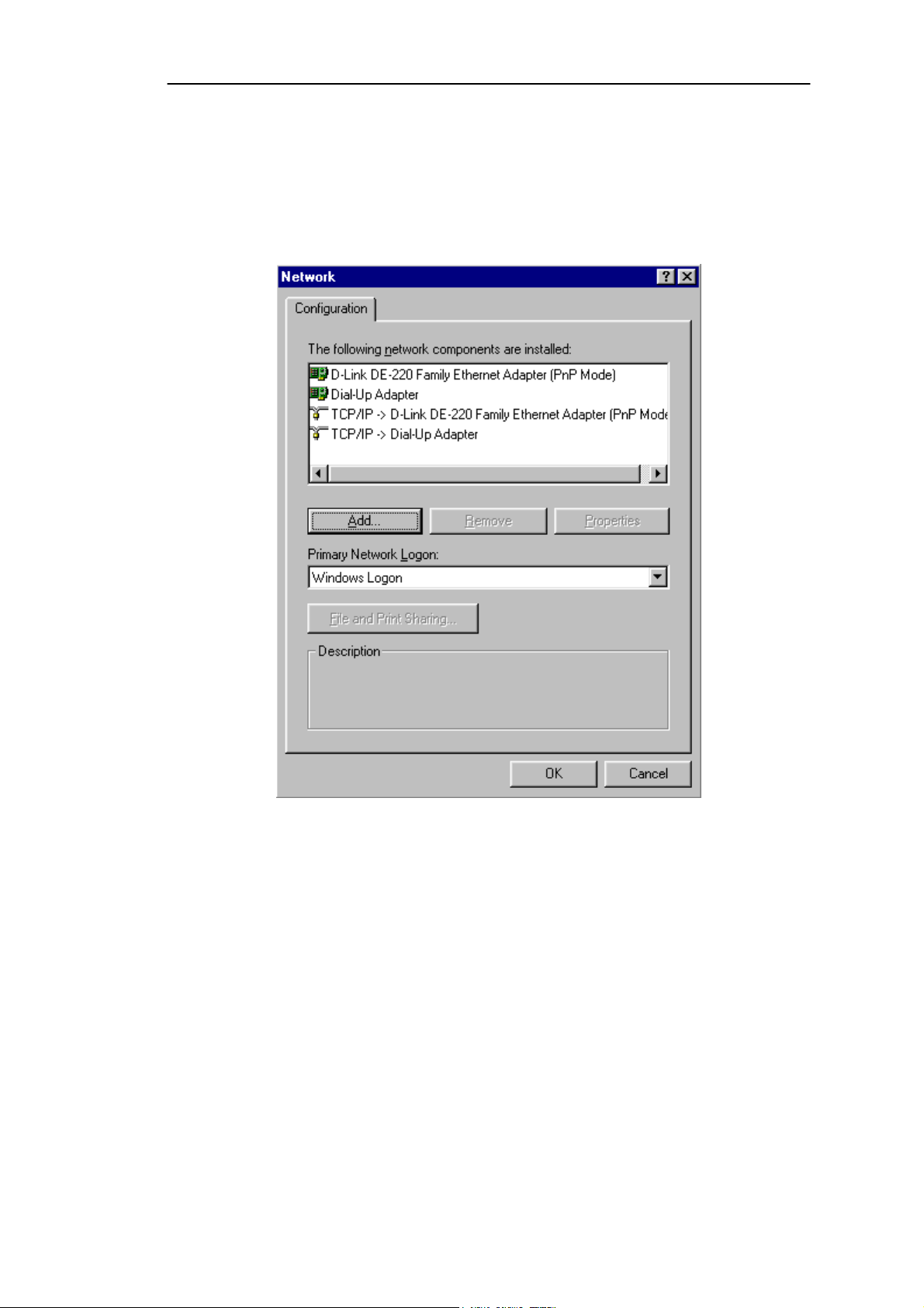
1. Click the Start button. Choose Settings and then Control Panel.
2. Double-click on the Network icon to bring up your Network window. Select
the Configuration tab.
3. Click the Add button.
36
Figure D-1
Page 38

Netgear CG814W Wireless Cable Modem Gateway
4. Double-click on Protocol.
5. Highlight Microsoft under the list of manufacturers.
6. Find and double-click TCP/IP in the list to the right (see Figure D-2).
Figure D-2
7. After a few seconds, the main Network window will appear. The TCP/IP
Protocol should now be listed.
37
Page 39

Netgear CG814W Wireless Cable Modem Gateway
Figure D-3
8. Click the OK button. Windows may ask for original Windows installation
files. Supply them as needed, e.g., c:\windows\options\cabs, D:\win98,
D:\win95, D:\win9x.
9. Windows will ask you to restart the PC. Click the Yes button.
The TCP/IP installation is now complete.
38
Page 40

Netgear CG814W Wireless Cable Modem Gateway
Appendix D: Finding the MAC Address
and IP Address for Your Ethernet
Adapter
This section describes how to find the MAC address for your Ethernet adapter.
You can also find the IP address of your computer’s Ethernet adapter. The IP
address is used for filtering, forwarding, and DMZ. Follow the steps in this
appendix to find the MAC address or IP address for your adapter in Windows
95, 98, Me, NT, 200, and XP.
For Windows 95, 98, and Me:
1. Click on Start and Run. In the Open field, enter winipcfg. Then press the
Enter key or the OK button.
Figure E-1
2. When the IP Configuration window appears, select the Ethernet adapter
you are using to connect to the Gateway via a CAT 5 Ethernet cable.
39
Figure E-2
Page 41

Netgear CG814W Wireless Cable Modem Gateway
3. Write down the Adapter Address as shown on your computer screen (see
Figure E-3). This is the MAC address for your Ethernet adapter and will be
shown as a series of numbers and letters.
Figure E-3
The example in Figure E-3 shows the IP address of your Ethernet adapter
as 192.168.45.131. Your computer may show something different.
Note: The MAC address is also called the Adapter Address.
40
Page 42

Netgear CG814W Wireless Cable Modem Gateway
For Windows NT, 2000, and XP:
The following steps show an alternative way of obtaining the MAC address
and IP address for your Ethernet adapter.
1. Click on Start and Run. In the Open field, enter cmd. Press the Enter key
or click the OK button.
2. In the command prompt, enter ipconfig /all. Then press the Enter key.
Figure E-4
3. Write down the Physical Address as shown on your computer screen; it is
the MAC address for your Ethernet adapter. This will appear as a series of
letters and numbers.
Note: The MAC address is also called the Adapter Address.
The example in Figure E-4 shows the IP address of your Ethernet adapter
as 192.168.100.10. Your computer may show something different.
41
Page 43

Netgear CG814W Wireless Cable Modem Gateway
Appendix E: Specfications
WAN Cable Interface F type female 75ohm
LAN 4 10/100 BASE-T
1 USB 1.1 Connector Type B
1 IEEE 802.11b (2.4 GHz Unlicensed ISM radio band)
CPU 140 MHz MIPS32-ISA
SDRAM 16Mb
Flash ROM
System Power
Power Supply
EMI/EMC FCC Class B, CE Class B, VCCI Class B.
Operation Requirement Operating Temp. 0ºC to 40ºC (32ºF to 104ºF)
16Mb
12V/700mA
12V/1.25A
Storage Temp. -20ºC to 70ºC (-4ºF to 158ºF)
Operating Humidity 10% to 85% Non-Condensing
Storage Humidity 5% to 90% Non-Condensing
Dimensions 186 x 155 x 63 (mm)
42
 Loading...