

Netgear orporated 26200345 User Manual
Installation
2nd Draft WAC740 QSG
NETGEAR ProSAFE Dual Band Wireless AC
Access Point
WAC740
Package Contents
Unpack the box and verify the contents:
• WAC740 ProSAFE Dual Band Wireless AC Access Point
• Category 5e Ethernet cable
• Ceiling mount kit
Set Up the Access Point
Before mounting the access point in a high location, first set up and test the
access point to verify WiFi network connectivity.
IMPORTANT: You can deploy the WAC740 access point only in a WiFi
network that is managed by a ProSAFE wireless controller.
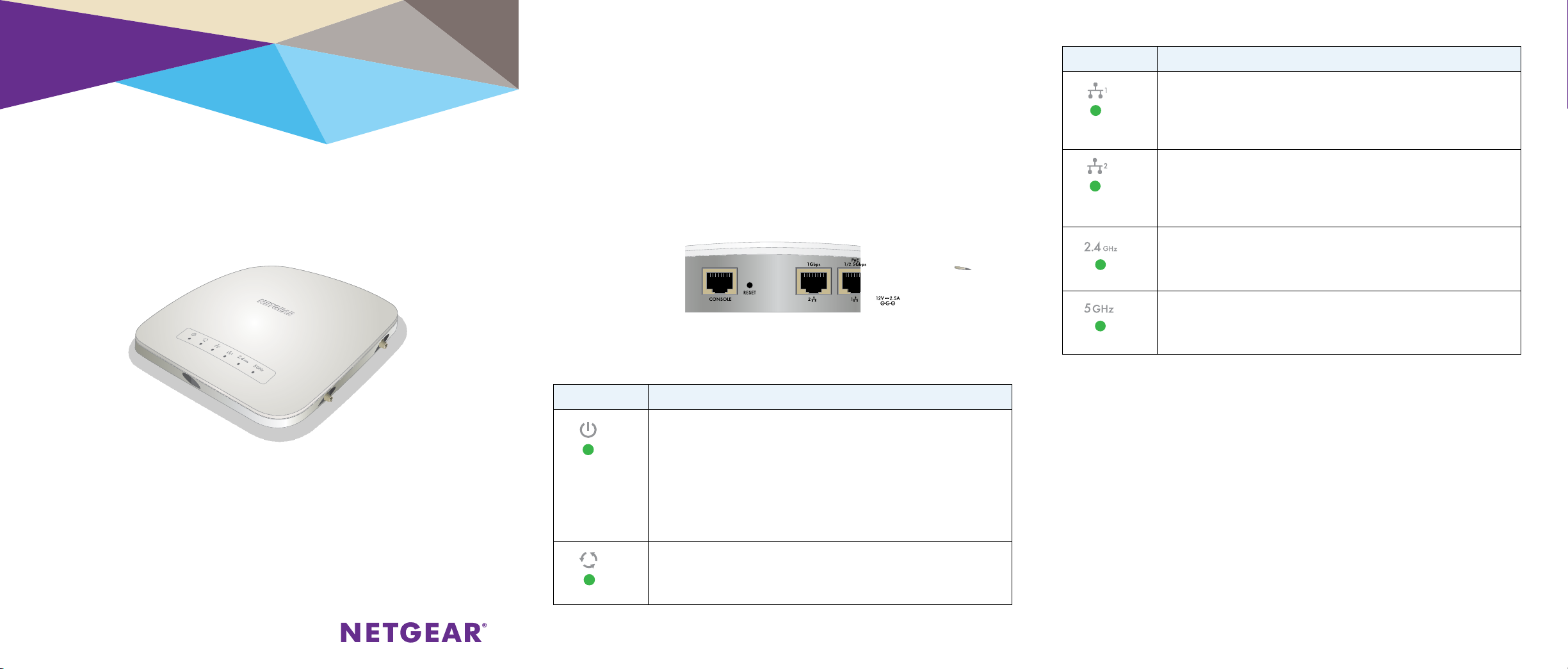
¾ To cable the access point:
1. Connect an Ethernet cable from LAN port 1 on the access point to a
LAN port on a PoE+ switch, that is, an 802.3at-compatible switch.
2. Connect an Ethernet cable from the PoE+ switch to an Ethernet port on
the computer.
3. Check the LEDs to verify that the access point is set up correctly.
LED Description
Power LED
Activity LED
•O. Power is o.
•Solid green. Power is on.
•Alternating green and amber. The access point receives insucient PoE
power.
•Solid amber, then blinking amber. A self-test is running or firmware is
being loaded. During startup, the Power LED first light solid amber, then
goes o, and then blinks amber before turning solid green aer about
one minute. If aer two minutes the Power LED remains solid amber or
continues to blink amber, it indicates a system fault.
•O. No link with the network is detected.
•Solid green. A link with the network is detected.
•Blinking green. Network trac is detected.
LED Description
LAN LED 1
LAN LED 2
2.4G WLAN LED
5G WLAN LED
•O. A 10 Mbps Ethernet link is detected or no Ethernet link is detected.
•Solid green. A 2.5 Gbps or 1 Gbps Mbps Ethernet link is detected.
If both LAN LED 1 and LAN LED 2 light solid green, the LAN ports are
members of a link aggregation group (LAG).
•Solid amber. A 100 Mbps Ethernet link is detected.
•O. A 10 Mbps Ethernet link is detected or no Ethernet link is detected.
•Solid green. A 1 Gbps Ethernet link is detected.
If both LAN LED 1 and LAN LED 2 light solid green, the LAN ports are
members of a link aggregation group (LAG).
•Solid amber. A 100 Mbps Ethernet link is detected.
•O. The 2.4 GHz WiFi radio is o.
•Solid green. The 2.4 GHz WiFi radio is on.
•Blinking green. WiFi activity is detected on the 2.4 GHz WiFi radio.
•O. The 5 GHz WiFi radio is o.
•Solid green. The 5 GHz WiFi radio is on.
•Blinking green. WiFi activity is detected on the 5 GHz WiFi radio.
The access point uses a DHCP client that is enabled by default. If your network
includes a DHCP server, the access point obtains an IP address from the DHCP
server. If your network does not include a DHCP server, the access point sets
its IP address to a static IP address of 192.168.0.160.
If your network includes a DHCP server, note the following:
• Make sure that option 43 is enabled on the DHCP server.
• Make sure that the DHCP server specifies the IP address of the wireless
controller.
• We recommend that you reserve an IP address for the access point on the
DHCP server.
If your network does not include a DHCP server, configure a computer with a
static IP address of 192.168.0.210 and a subnet mask of 255.255.255.0 so
you can connect to the access point at IP address 192.168.0.160.
¾ To verify that the access point’s obtained IP address information,
2nd Draft WAC740 QSG
or if your network does not include a DHCP server, to configure
the access point’s IP address information:
1. Open a web browser from a computer that is connected to the same
network as the access point or to the access point directly through an
Ethernet cable.
2. In the address bar, enter the IP address of the access point.
The default IP address is 192.168.0.160.
A login window displays.
3. Enter the user name and password.
The user name is admin. The default password is password. The user
name and password are case-sensitive.
4. Select Configuration > System > Basic > Network Settings > IP
Settings.
5. Verify or configure the IP settings for your network.
6. Select Configuration > System > Network Settings > Controller
Settings .
7. Verify or configure the IP address for the wireless controller in the
network.
For more information, see the ProSAFE wireless controller user manual.
¾ To let the wireless controller discover the access point:
1. Access the wireless controller at its network IP address.
2. Select Access Point > Discovery Wizard.
3. Follow the steps onscreen to discover the access point and review the
discovery results.
4. In the table with discovered access points, select the check box for the
access point, and click the Add button.
The access point is added to the Managed AP List and is now ready for
further configuration and management by the wireless controller.
For more information, see the ProSAFE wireless controller user manual.
NETGEAR INTL LTD
Building 3, University Technology Centre
Curraheen Road, Cork, Ireland
Deploy the Access Point
The best location for the access point is elevated such as wall or ceiling
mounted, at the center of the WiFi coverage area, and within line of sight of
all mobile devices.
For information about mounting the access point, see the ceiling and wall
installation guide for the WAC720, WAC730, and WAC740.
¾ To deploy the access point:
1. Disconnect the access point and position it where you will deploy it.
2. Connect an Ethernet cable from the access point to a LAN port on a
PoE + switch.
3. Make sure that the PoE+ switch and the wireless controller are
connected.
4. Using a WiFi device, verify connectivity by connecting to the access
point and use a browser to connect to the Internet.
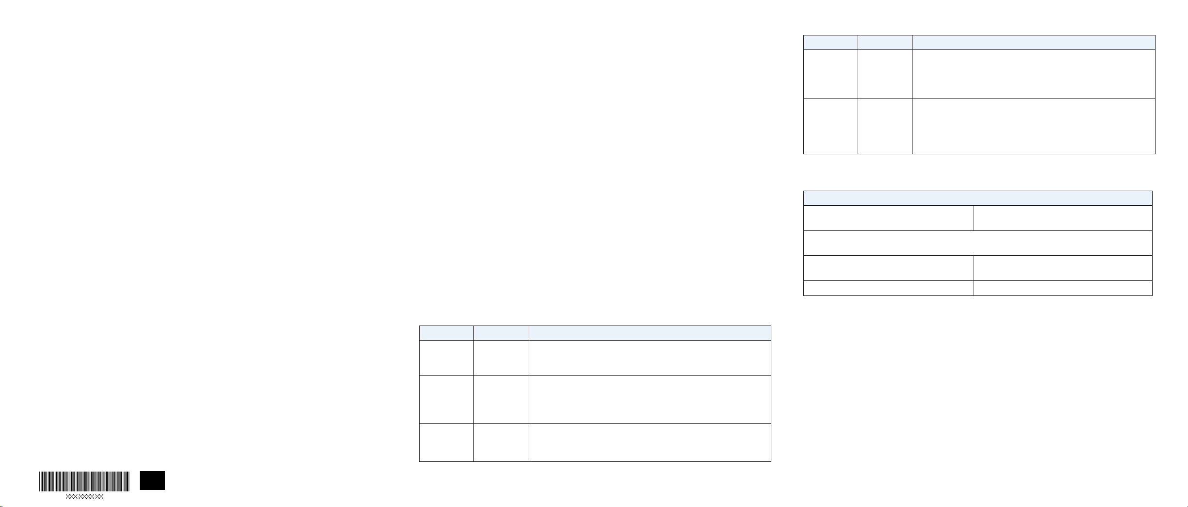
Troubleshooting Tips
The following table provides some tips for correcting simple problems
that you might encounter. For more troubleshooting information, see the
troubleshooting chapter in the ProSAFE wireless controller user manual.
Problem Cause Possible Solution
No LEDs are lit
on the access
point
The Power
LED alternates
green and
amber
The LAN port
LEDs are o
The access
point receives
no power
The access
point receives
insucient
PoE power
A hardware
connection
problem exists
•Make sure that the access point is securely connected to a PoE+ switch.
•Make sure that the PoE+ switch is connected to a power source.
•Make sure that PoE+ switch is not overloaded.
•If you connected the access point to a PoE (802.3af) switch, disconnect
it and connect it to a PoE+ (802.3at) switch instead. The access point
requires a PoE+ (802.3at) switch.
•Make sure that the cable connectors are securely plugged into the
access point and switch.
• Make sure that the switch is turned on.
Problem Cause Possible Solution
The WLAN
LEDs are o
You cannot
connect to
the access
point from a
browser
The wireless
connection
does not work
Multiple
possible
causes
•Make sure the PoE+ switch is providing sucient power to the access
point.
•From the wireless controller, verify that the radio or radios are turned on.
•If the WLAN LEDs remain o, contact NETGEAR.
•Make sure that your computer is using an IP address in the same
range as the access point. The access point default IP address is
192.168.0.160, and the default subnet mask is 255.255.255.0.
•Quit the browser, clear the cache, delete the cookies, and launch the
browser again.
Technical Specifications
Electrical, Physical, and Environmental Specifications
PoE+: 802.3at (42V~57VDc, 600mA) Optional power adapter: 12 VDC, 2.5A
The plug is localized to the country of sale.
Safety precaution: PoE may be considered a Network Environment 0 per IEC TR 62101, and thus the
interconnected ITE circuits may be considered SELV.
Height x Width x Depth: 7.76 x 7.76 x 1.57 in
(197.3 x 197.3 x 40 mm)
Operating temperature: 32 to 104°F (0 to 40°C) Operating humidity: 10–90%, noncondensing
Weight: 1.73 lb. (785 g)
Support
Thank you for purchasing this NETGEAR product. You can visit
www.netgear.com/support to register your product, get help, access the latest
downloads and user manuals, and join our community. We recommend that you
use only ocial NETGEAR support resources.
For the current EU Declaration of Conformity, visit
http://support.netgear.com/app/answers/detail/a_id/11621/.
For regulatory compliance information, visit
http://www.netgear.com/about/regulatory/.
See the regulatory compliance document before connecting the power supply.
NETGEAR, Inc.
350 East Plumeria Drive
San Jose, CA 95134, USA
© NETGEAR, Inc., NETGEAR and the NETGEAR Logo
are trademarks of NETGEAR, Inc. Any non‑NETGEAR
trademarks are used for reference purposes only.
June 2016
 Loading...