

Easy, Reliable & Secure
User Manual
N300 WiFi Router (N300R) User Manual
202-11001-01
May 2012

Trademarks
Brand and product names are trademarks or registered trademarks of their respective holders. Information is subject to
change without notice.
In the interest of improving internal design, operational function, and/or reliability, On Networks reserves the right to
make changes to the products described in this document without notice. On Networks does not assume any liability that
may occur due to the use or application of the product(s) or circuit layout(s) described herein.
This symbol is placed in accordance with the European Union Directive 2002/96 on the Waste Electrical and
Electronic Equipment (the WEEE Directive). If disposed of within the European Union, this product should be
treated and recycled in accordance with the laws of your jurisdiction implementing the WEEE Directive.
ii
May 2012

Contents
Chapter 1
Configuring Basic Connectivity
Powering On Your Wireless Router.................................................................................1-1
Logging In To Your Wireless Router ..............................................................................1-1
Configuring Your Internet Connection Using the Smart Setup Wizard ...........................1-5
Viewing and Configuring Basic ISP Settings ..................................................................1-5
Setting Up and Testing Basic Wireless Connectivity ....................................................1-10
Chapter 2
Safeguarding Your Network
Choosing Appropriate Wireless Security ........................................................................2-1
Recording Basic Wireless Settings Setup Information ...................................................2-5
Changing Wireless Security Settings .............................................................................2-6
Viewing Basic Wireless Settings ..............................................................................2-6
Configuring WEP Wireless Security .........................................................................2-9
Configuring WPA-PSK and WPA2-PSK Wireless Security ....................................2-10
Viewing Advanced Wireless Settings ...........................................................................2-12
Using Push 'N' Connect (Wi-Fi Protected Setup) .........................................................2-13
Push Button Configuration .....................................................................................2-14
Security PIN Entry ..................................................................................................2-15
Configuring the WPS Settings ................................................................................2-17
Connecting Additional Wireless Client Devices after WPS Setup ..........................2-18
Restricting Wireless Access by MAC Address .............................................................2-19
Changing the Administrator Password .........................................................................2-21
Backing Up Your Configuration ....................................................................................2-22
Live Parental Controls...................................................................................................2-23
Understanding Your Firewall ........................................................................................2-23
v1.0, May 2012
vii

N300 WiFi Router (N300R) User Manual
Chapter 3
Restricting Access From Your Network
Content Filtering Overview .............................................................................................3-1
Blocking Access to Internet Sites ...................................................................................3-1
Blocking Access to Internet Services .............................................................................3-3
Blocking Services by IP Address Range ..................................................................3-5
Scheduling Blocking .......................................................................................................3-5
Viewing Logs of Web Access or Attempted Web Access ...............................................3-6
Configuring E-mail Alert and Web Access Log Notifications ..........................................3-7
Chapter 4
Customizing Your Network Settings
Using the LAN IP Setup Options ....................................................................................4-1
Configuring a Device Name .....................................................................................4-2
Configuring LAN TCP/IP Setup Parameters ............................................................4-3
Using the Router as a DHCP Server ........................................................................4-4
Using Address Reservation ......................................................................................4-5
Using a Dynamic DNS Service .......................................................................................4-6
Configuring the WAN Setup Options ..............................................................................4-8
Disabling Prt Scan and DoS Protection ....................................................................4-8
Setting Up a Default DMZ Server .............................................................................4-8
Responding to a Ping on the Internet (WAN) Port ...................................................4-9
Ebling IBMP Proxying ...............................................................................................4-9
Setting the MTU Size .............................................................................................4-10
Configuring NAT Filtering .......................................................................................4-10
Configuring Static Routes .............................................................................................4-10
Wireless Repeating (Also Called WDS) .......................................................................4-12
Wireless Repeating Function .................................................................................4-13
Setting Up the Base Station ...................................................................................4-14
Setting Up a Repeater Unit ....................................................................................4-15
viii Contents
v1.0, May 2012

N300 WiFi Router (N300R) User Manual
Chapter 5
Fine-Tuning Your Network
Allowing Inbound Connections to Your Network ............................................................5-1
How Your Computer Accesses a Remote Computer through Your Router .............5-2
How Port Triggering Changes the Communication Process ....................................5-3
How Port Forwarding Changes the Communication Process ..................................5-5
How Port Forwarding Differs from Port Triggering ...................................................5-6
Configuring Port Forwarding to Local Servers ................................................................5-6
Adding a Custom Service .........................................................................................5-7
Editing or Deleting a Port Forwarding Entry .............................................................5-9
Configuring Port Triggering ..........................................................................................5-10
Using Universal Plug and Play .....................................................................................5-14
Optimizing Wireless Performance ................................................................................5-15
Changing the MTU Size ...............................................................................................5-16
Quality of Service .........................................................................................................5-18
Using WMM QoS for Wireless Multimedia Applications .........................................5-18
Configuring QoS for Internet Access ......................................................................5-18
Overview of Home and Small Office Networking Technologies ...................................5-24
Assessing Your Speed Requirements ...................................................................5-25
Chapter 6
Using Network Monitoring Tools
Viewing Wireless Router Status Information ..................................................................6-2
Viewing a List of Attached Devices ................................................................................6-7
Managing the Configuration File .....................................................................................6-7
Backing Up and Restoring the Configuration ...........................................................6-8
Erasing the Configuration .........................................................................................6-9
Updating the Router Firmware .......................................................................................6-9
Checking for New Firmware in the Router Upgrade Screen ..................................6-10
Updating Manually to New Router Firmware .........................................................6-11
Enabling Remote Management Access .......................................................................6-13
Traffic Meter ..................................................................................................................6-15
Contents ix
v1.0, May 2012

N300 WiFi Router (N300R) User Manual
Chapter 7
Troubleshooting
Quick Tips .......................................................................................................................7-1
Troubleshooting Basic Functions ...................................................................................7-2
Login Problems ...............................................................................................................7-4
Checking the Internet Service Connection .....................................................................7-5
Obtaining an Internet IP Address .............................................................................7-5
Troubleshooting PPPoE ...........................................................................................7-6
Troubleshooting Internet Browsing ..........................................................................7-7
Troubleshooting Your Network Using the Ping Utility .....................................................7-7
Testing the LAN Path to Your Router .......................................................................7-8
Testing the Path from Your Computer to a Remote Device .....................................7-9
Problems with Date and Time ........................................................................................7-9
Problems with Wireless Adapter Connections ..............................................................7-10
Restoring the Default Configuration and Password ......................................................7-11
Appendix A
Technical Specifications
Default Configuration Settings ....................................................................................... A-1
General Specifications ................................................................................................... A-3
Appendix B
Related Documents
Index
x Contents
v1.0, May 2012

Chapter 1
Configuring Basic Connectivity
This chapter describes the settings for your Internet connection and your wireless local area
network (LAN) connection. This chapter provides further details about connectivity settings, as
well as instructions on how to log in to the router for further configuration.This chapter includes
the following sections:
• “Logging In To Your WiFi Router”
• “Configuring Your Internet Connection Using the Smart Setup Wizard” on page 1-5
• “Viewing and Configuring Basic ISP Settings” on page 1-5
• “Setting Up and Testing Basic Wireless Connectivity” on page 1-11
Logging In To Your WiFi Router
When the WiFi router is connected to your network, you can access and configure the router using
your browser.
To access the router:
1. Connect to the WiFi router by typing http://www.routerlogin.com in the address field of your
browser, and then press Enter. A login window displays.
Figure 1-1
1-1
May 2012
N300 WiFi Router (N300R) User Manual
Tip: You can connect to the WiFi router by typing either of these URLs in the
address field of your browser, and then pressing Enter:
• http://www.routerlogin.net
• http://www.routerlogin.com
If these URLs do not work, you must type the IP address of the router, for
example, http://www.192.168.1.1.
2. Enter admin for the router user name and your password (or the default, password). For
information about how to change the password, see “Changing the Administrator Password”
on page 2-21.
Note: The router user name and password are not the same as any other user name or
password you might use to log in to your Internet connection.
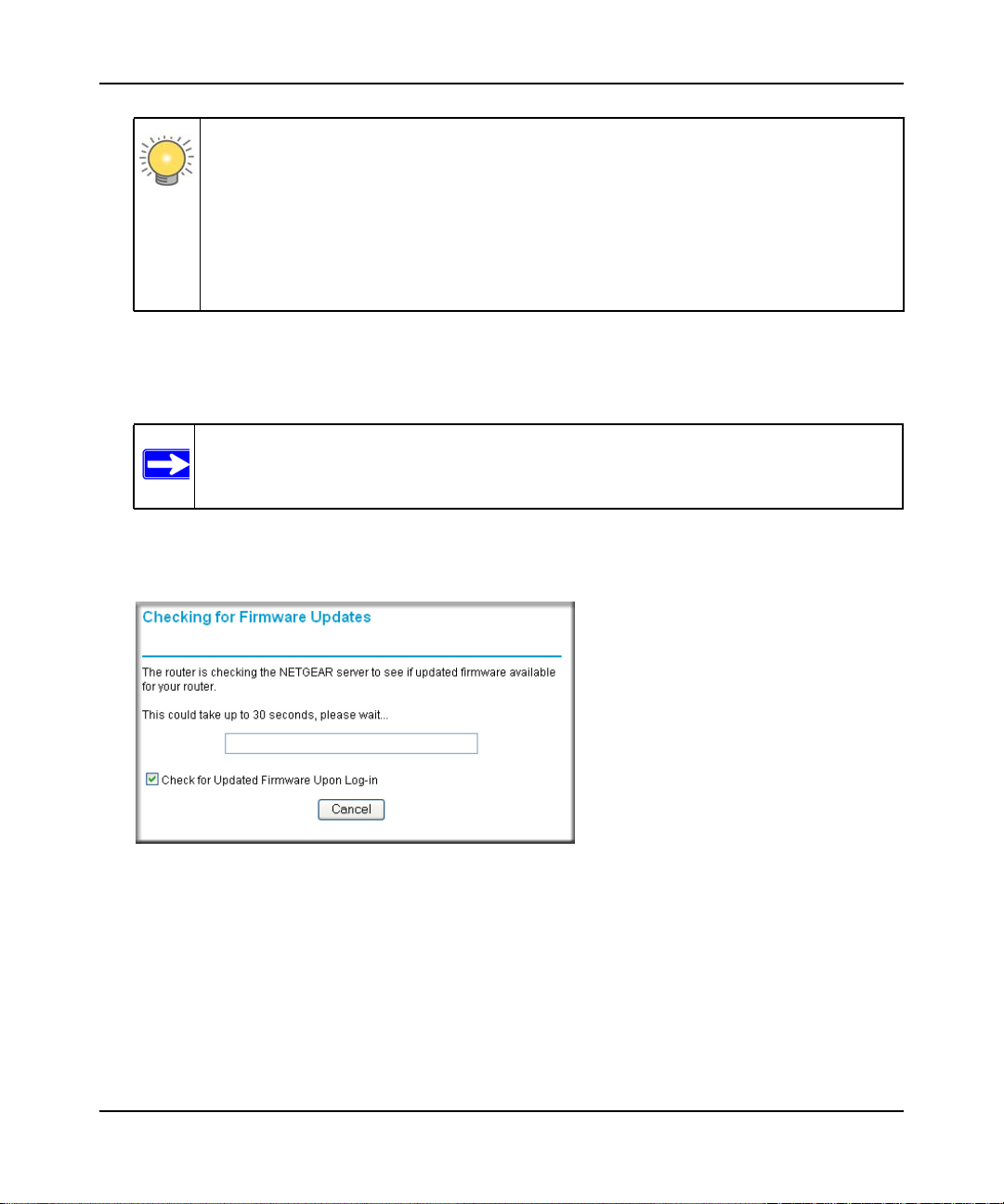
The Checking for Firmware Updates screen appears unless you previously cleared the Check
for Updated Firmware Upon Log-in check box.
Figure 1-2
1-2 Configuring Basic Connectivity
v1.0, May 2012
N300 WiFi Router (N300R) User Manual
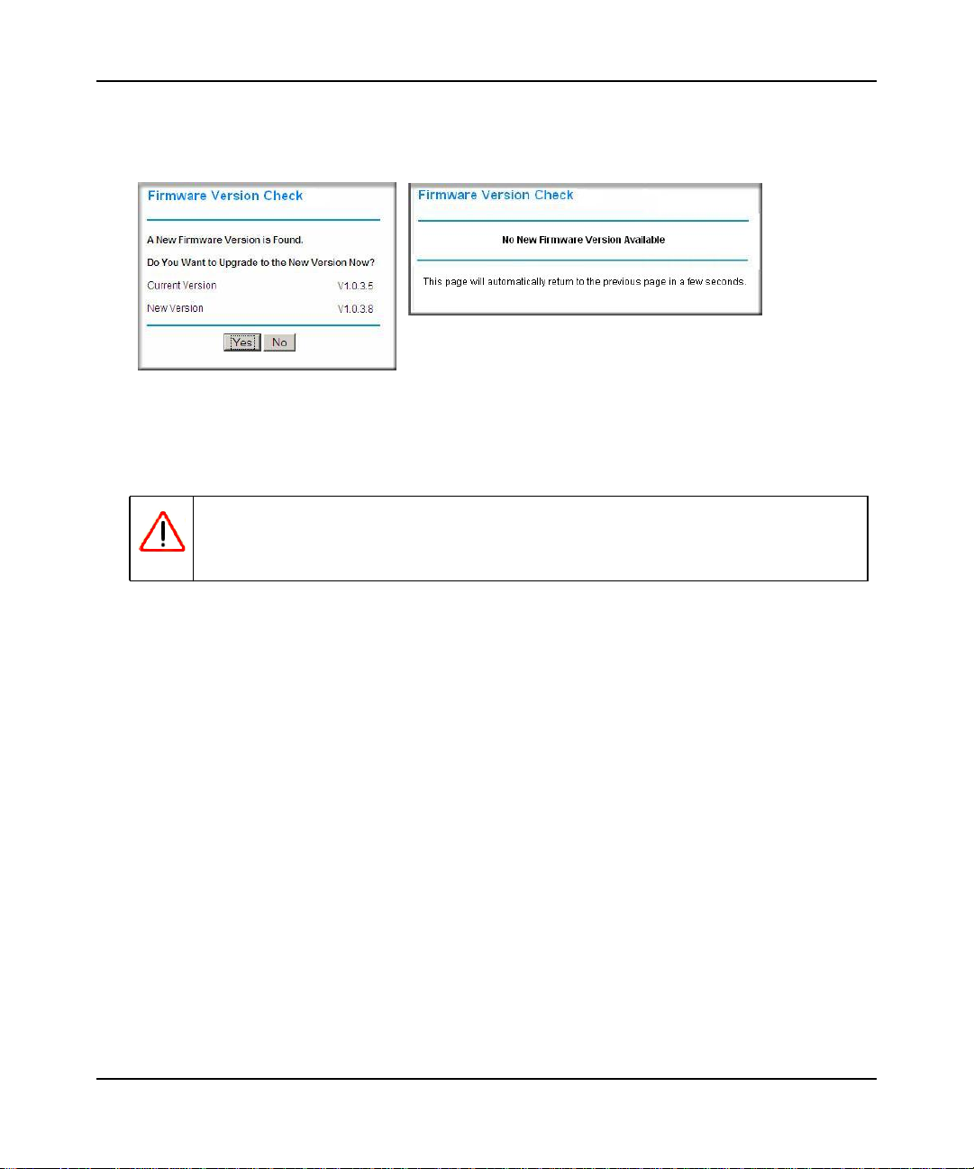
If the router discovers a newer version of firmware, the message on the left displays when you
log in. If no new firmware is available, the message on the right displays.
Figure 1-3
To automatically update to the new firmware, click Yes to allow the router to download and
install the new firmware file from On Networks.
Warning: When uploading firmware to the N300R router, do not interrupt the Web
browser by closing the window, clicking a link, or loading a new page. If
the browser is interrupted, it could corrupt the firmware.
When the upload is complete, your router automatically restarts. The update process typically
takes about 1 minute.
3. In the main menu on the left, select Basic Settings under Setup. The Basic Settings screen
displays showing the WiFi router’s home page and suggested default settings.
Configuring Basic Connectivity 1-3
May 2012
N300 WiFi Router (N300R) User Manual
Figure 1-4
Note: If the Check for New Version Upon Log-in check box is selected, the home
page is the Router Upgrade screen. Otherwise, it is the Basic Settings screen.
If the WiFi router is connected to the Internet, you can select Knowledge Base under Web
Support in the main menu to view support information for the WiFi router.
If you do not click Logout, the WiFi router will wait for 5 minutes after no activity before it
automatically logs you out.
1-4 Configuring Basic Connectivity
v1.0, May 2012

N300 WiFi Router (N300R) User Manual
Configuring Your Internet Connection Using the Smart Setup Wizard
You can manually configure your Internet connection using the Basic Settings screen, or you can
allow the Smart Setup Wizard to determine your Internet Service Provider (ISP) configuration.
The Smart Setup Wizard searches your Internet connection for servers and protocols to determine
your ISP configuration.
To use the Smart Setup Wizard to assist with configuration or to verify the Internet connection
settings:
1. Select Setup Wizard from the top of the main menu.
2. Click Next to proceed. Enter your ISP settings, as needed.
3. At the end of the Setup Wizard, click Test to verify your Internet connection. If you have
trouble connecting to the Internet, see Chapter 7, “Troubleshooting.”
Viewing and Configuring Basic ISP Settings
Settings related to your Internet service are specified in the Basic Settings screen. Select Basic
Settings under Setup in the main menu.
The content you see in the Basic Settings screen depends on whether your ISP requires that you
log in with a user name and password for Internet access.
• No login required by ISP. If no login is required by your ISP, the following settings appear in
the Basic Settings screen.
Configuring Basic Connectivity 1-5
May 2012

N300 WiFi Router (N300R) User Manual
ISP does not require login
Figure 1-5
– Account Name (might also be called Host Name). The account name is provided to the
ISP during a DHCP request from your router. In most cases, this setting is not required,
but some ISPs require it for access to ISP services such as mail or news servers.
– Domain Name. The domain name is provided by your router to computers on your LAN
when the computers request DHCP settings from your router. In most cases, this settings is
not required.
1-6 Configuring Basic Connectivity
v1.0, May 2012
N300 WiFi Router (N300R) User Manual
– Internet IP Address. Determines how your router obtains an IP address for Internet
access.
• If your ISP assigns an IP address dynamically (by DHCP), select Get Dynamically
From ISP.
• If your ISP has assigned you a permanent, fixed (static) IP address for your computer,
select Use Static IP Address. Enter the IP address that your ISP assigned. Also, enter
the subnet mask and the gateway IP address. The gateway is the ISP’s router to which
your router will connect.
– Domain Name Server (DNS) Address. If you know that your ISP does not automatically
transmit DNS addresses to the router during login, select Use These DNS Servers, and
enter the IP address of your ISP’s primary DNS server. If a secondary DNS server address
is available, enter it also.
Note: If you enter or change a DNS address, restart the computers on your
network so that these settings take effect.
– Router MAC Address. This section determines the Ethernet MAC address that the router
will use on the Internet port. Typically, you would leave Use Default Address selected.
However, some ISPs (especially cable modem providers) register the Ethernet MAC
address of the network interface card in your computer when your account is first opened.
They then accept only traffic from the MAC address of that computer. This feature allows
your router to masquerade as that computer by “cloning” or “spoofing” its MAC address.
To change the MAC address, select one of the following methods:
• Select Use Computer MAC Address. The router will then capture and use the MAC
address of the computer that you are now using. You must be using the one computer
that is allowed by the ISP.
• Select Use This MAC Address, and enter it here.
Configuring Basic Connectivity 1-7
May 2012
N300 WiFi Router (N300R) User Manual
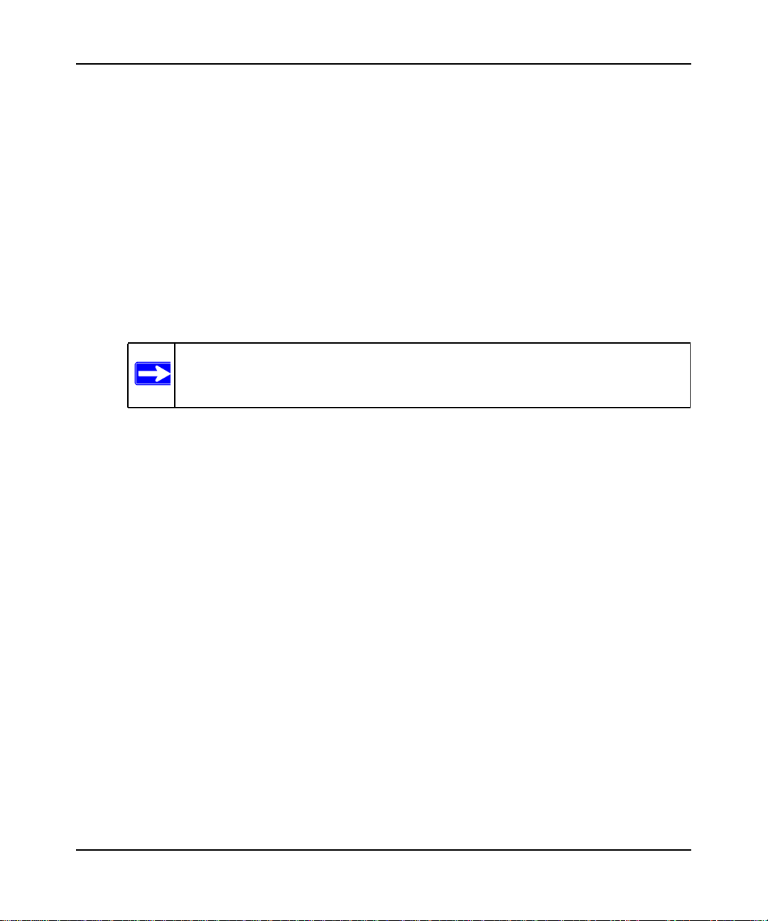
If a login is required by your ISP, the following settings appear in the Basic Settings screen:
ISP does require login
Figure 1-6
1-8 Configuring Basic Connectivity
v1.0, May 2012
N300 WiFi Router (N300R) User Manual
• Does Your Internet Connection Require A Login? If you usually must use a login program
such as WinPOET to access the Internet, your Internet connection requires a login. After you
select Yes, the Basic Settings screen displays.
Note: After you finish setting up your router, you will no longer need to launch the
ISP’s login program on your computer to access the Internet. When you start
an Internet application, your router will automatically log you in.
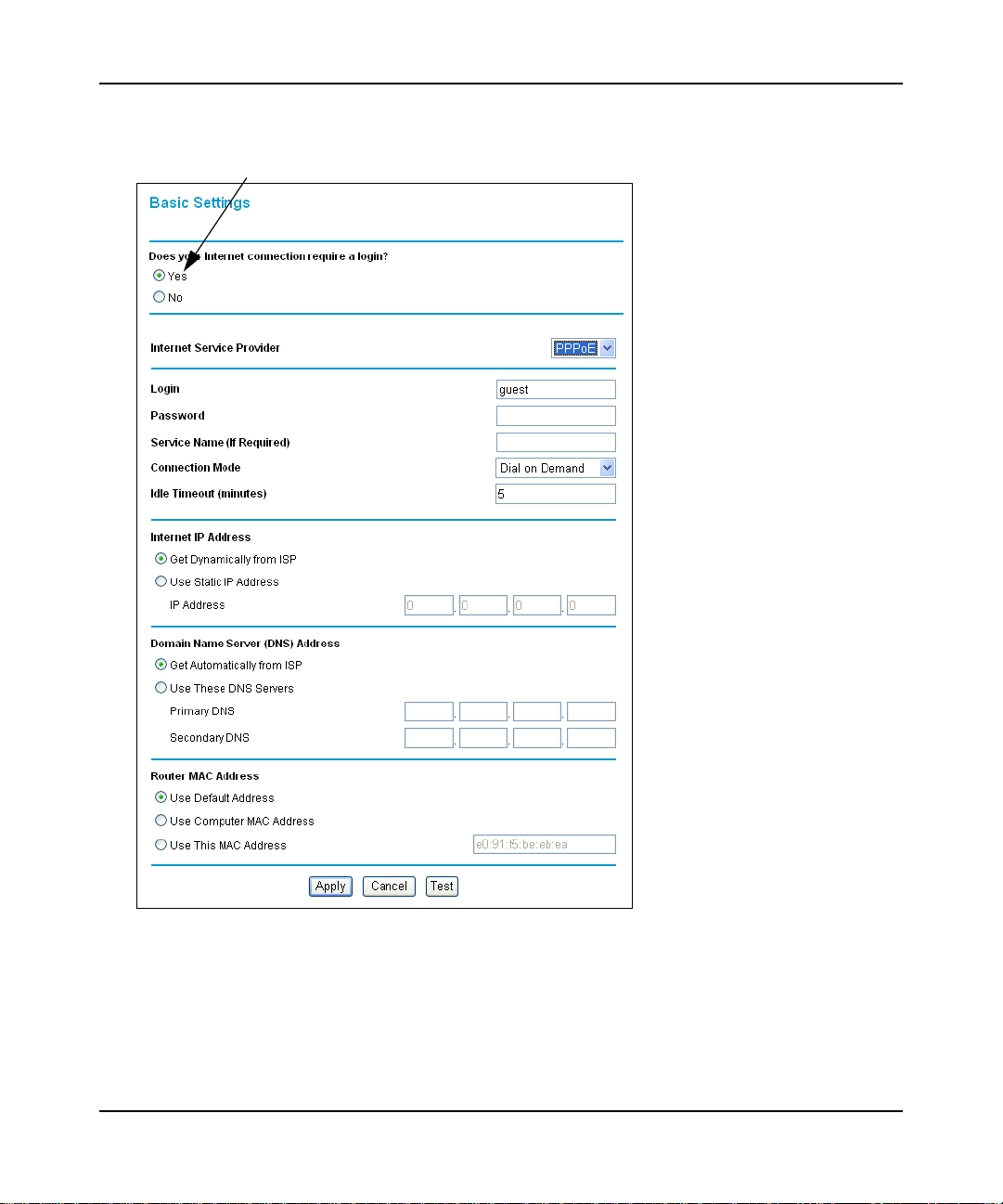
– Internet Service Provider. This drop-down list contains a few ISPs that need special
protocols for connection. The list includes:
• PPTP (Point to Point Tunneling Protocol), used primarily in Austrian DSL services.
• PPPoE (Point to Point Protocol over Ethernet), the protocol used by most DSL
services worldwide.
• L2TP (Layer 2 Tunneling Protocol), used to support virtual private networks (VPNs).
Figure 1-7
Note: Not all ISPs are listed here. The ones on this list have special
requirements.
– Login and Password. This is the user name and password provided by your ISP. This
name and password are used to log in to the ISP server.
– Service Name. If your connection is capable of connecting to multiple Internet services,
this setting specifies which service to use.
Configuring Basic Connectivity 1-9
May 2012
N300 WiFi Router (N300R) User Manual
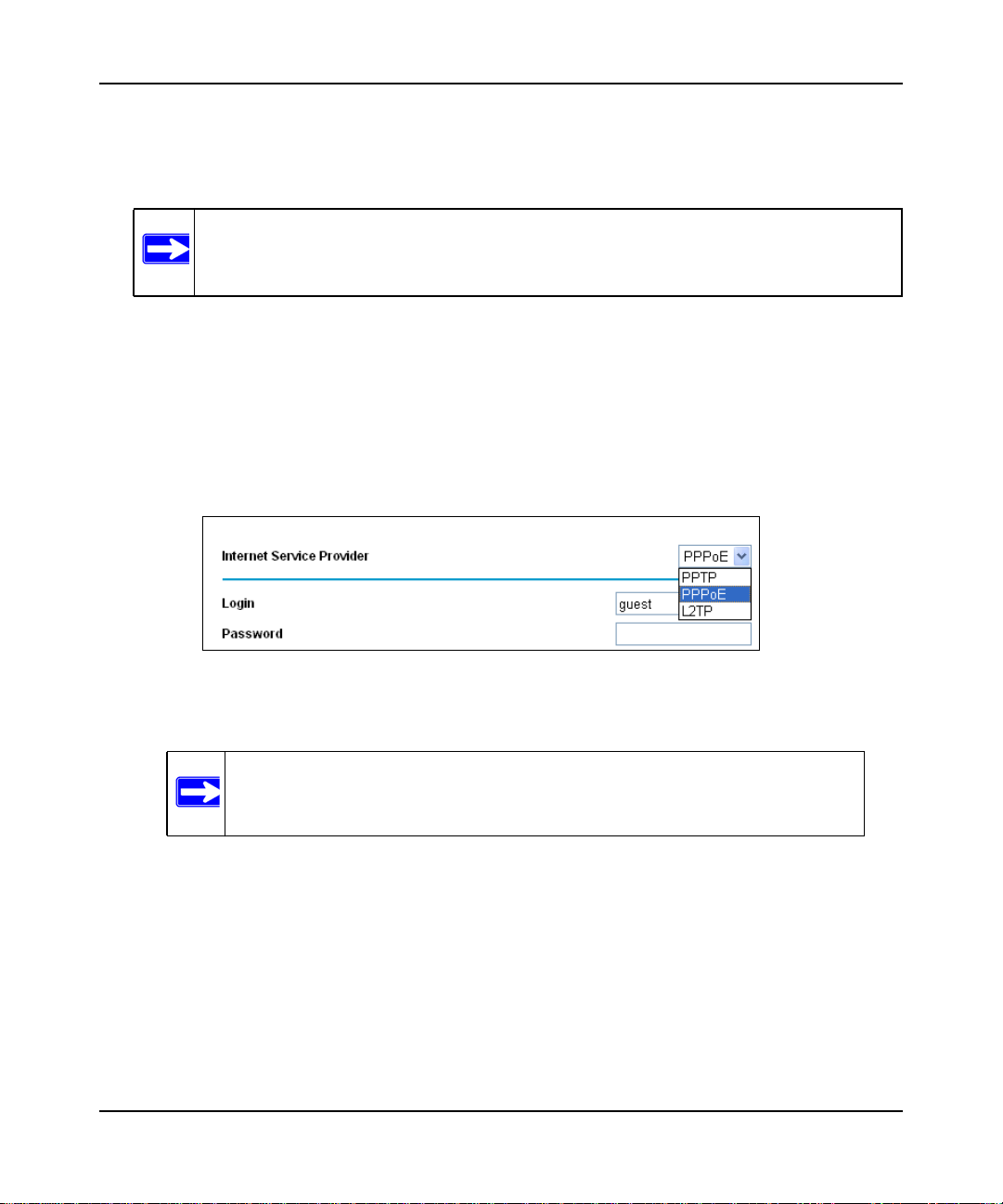
• Connection Mode. This drop-down list selects when the router will connect to and
disconnect from the Internet.
Figure 1-8
– The list includes:
• Always On. The router logs in to the Internet immediately after booting and never
disconnects.
• Dial on Demand. The router logs in only when outgoing traffic is present and logs out
after the idle time-out.
• Manually Connect. The router logs in or logs out only when the user clicks Connect
or Disconnect in the Router Status screen.
– Idle Timeout. Your Internet connection is logged out if there is no data transfer during the
specified time interval.
– Domain Name Server (DNS) Address. If you know that your ISP does not automatically
transmit DNS addresses to the router during login, select Use These DNS Servers, and
enter the IP address of your ISP’s primary DNS server. If a secondary DNS server address
is available, enter it also.
Note: If you enter or change a DNS address, restart the computers on your
network so that these settings take effect.
– Router MAC Address. Select the default router MAC address, the computer MAC
address, or a MAC address that you specify.
1-10 Configuring Basic Connectivity
v1.0, May 2012
N300 WiFi Router (N300R) User Manual
Setting Up and Testing Basic Wireless Connectivity
Note: If you use a wireless computer to change wireless settings, you might be
disconnected when you click Apply. Reconfigure your wireless adapter to match
the new settings, or access the router from a wired computer to make any further
changes.
Follow these instructions to set up and test basic wireless connectivity. Once you have established
basic wireless connectivity, you can enable security settings appropriate to your needs.
1. Select Wireless Settings under Setup in the main menu of the N300R router.
Figure 1-9
2. For the wireless network name (SSID), use the default name, or choose a suitable descriptive
name. In the Name (SSID) field, you can enter a value of up to 32 alphanumeric characters.
The default SSID is On Networks.
Note: The SSID is case-sensitive. Also, the SSID of any wireless access adapters
must match the SSID you specify in the N300R router. If they do not match,
you will not get a wireless connection to the N300R router.
Configuring Basic Connectivity 1-11
May 2012
N300 WiFi Router (N300R) User Manual
3. Select the region in which the wireless interface will operate.
Note: In North America, the region cannot be changed, and is set by default to US.
4. Set the channel. The default channel is Auto.
This field determines which operating frequency is used. It should not be necessary to change
the wireless channel unless you notice interference problems with another nearby wireless
router or access point. Select a channel that is not being used by any other wireless networks
within several hundred feet of your router.
5. Make sure that the mode is set to Up to 145Mbps.
6. For Security Options, select None.
7. Click Apply to save your changes.
Note: If you are configuring the router from a wireless computer and you change the
router’s SSID, channel, or security settings, you will lose your wireless
connection when you click Apply. You must then change the wireless settings
of your computer to match the router’s new settings.
1-12 Configuring Basic Connectivity
v1.0, May 2012
N300 WiFi Router (N300R) User Manual
8. Select Advanced Wireless Settings under Advanced in the main menu of the N300R router.
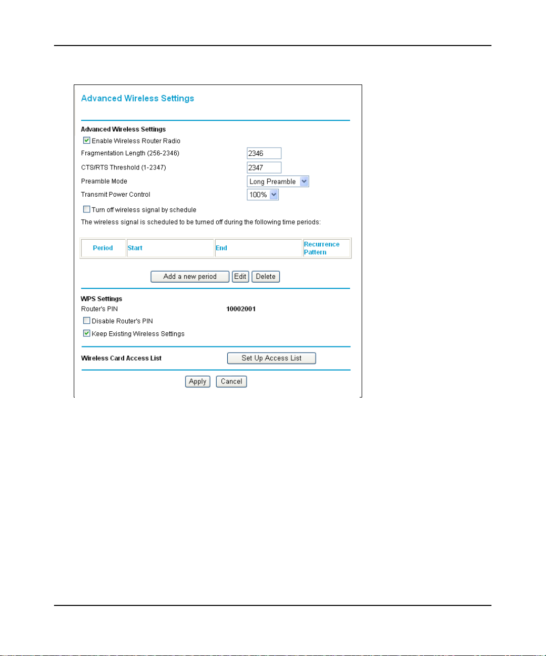
Figure 1-10
9. Make sure that the Enable Wireless Router Radio check box is selected.
10. Click Setup Access List.
11. Make sure that the Turn Access Control On check box is not selected.
Configuring Basic Connectivity 1-13
May 2012

N300 WiFi Router (N300R) User Manual
12. Configure and test your wireless computer for wireless connectivity.
Program the wireless adapter of your computer to have the same SSID and channel that you
specified in the router, and disable encryption. Check that your computer has a wireless link
and can obtain an IP address by DHCP from the router.
Once your computer has basic wireless connectivity to the router, you can configure the advanced
wireless security functions of the computer and router (for more information about security and
these settings, see Chapter 2, “Safeguarding Your Network ”).
1-14 Configuring Basic Connectivity
v1.0, May 2012

Chapter 2
Safeguarding Your Network
The N300 WiFi Router (N300R) provides highly effective security features, which are covered in
detail in this chapter.
This chapter includes the following sections:
• “Choosing Appropriate Wireless Security”
• “Recording Basic Wireless Settings Setup Information” on page 2-5
• “Changing Wireless Security Settings” on page 2-6
• “Viewing Advanced Wireless Settings” on page 2-12
• “Using WPS Push Button Connect (Wi-Fi Protected Setup)” on page 2-13
• “Restricting Wireless Access by MAC Address” on page 2-19
• “Changing the Administrator Password” on page 2-21
• “Backing Up Your Configuration” on page 2-22
• “Live Parental Controls” on page 2-23
• “Understanding Your Firewall” on page 2-23
Choosing Appropriate Wireless Security
Unlike wired networks, wireless networks allow anyone with a compatible adapter to receive your
wireless data transmissions well beyond your walls. Operating an unsecured wireless network
creates an opportunity for outsiders to eavesdrop on your network traffic or to enter your network
to access your computers and files. Indoors, computers can connect over 802.11g/n wireless
networks at ranges of up to 300 feet. Such distances can allow for others outside your immediate
area to access your network. Use the security features of your wireless equipment that are
appropriate to your needs.
The time it takes to establish a wireless connection can vary depending on both your security
settings and router placement.
2-1
v1.0, May 2012
N300 WiFi Router (N300R) User Manual
Stronger security methods can entail a cost in terms of throughput, latency, battery consumption,
and equipment compatibility. In choosing an appropriate security level, you can also consider the
effort compared to the reward for a hacker to break into your network. As a minimum, however,
On Networks recommends using WEP with Shared Key authentication. Do not run an unsecured
wireless network unless it is your intention to provide free Internet access for the public.
WEP connections can take slightly longer to establish. Also, WEP, WPA-PSK, and WPA2-PSK
encryption can consume more battery power on a notebook computer, and can cause significant
performance degradation with a slow computer.
Note: On Networks recommends that you change the administration password of your
router. Default passwords are well known, and an intruder can use your
administrator access to read or disable your security settings. For information
about how to change the administrator password, see “Changing the Administrator
Password” on page 2-21.
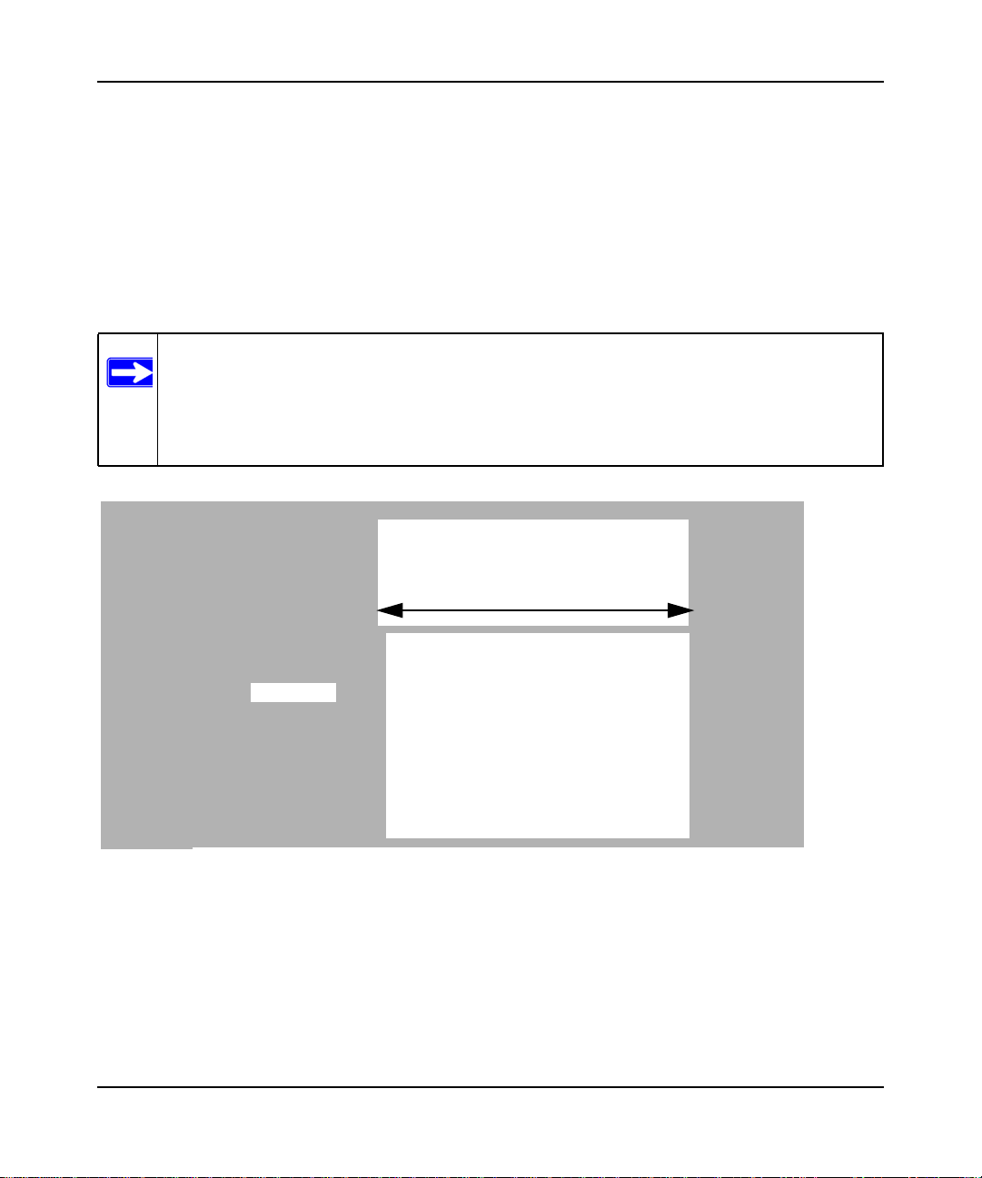
Wireless data
security options
Range: up to 300 foot radius
1) Open system: easy but no security
2) MAC access list: no data security
JWNR2000
Note: Use these with other features that enhance security (Table 2-2 on page 2-4).
Figure 2-1
v2
3) WEP: security but some performance
impact
4) WPA-PSK: strong security
5) WPA2-PSK: very strong security
To configure the wireless network, you can:
• Manually specify your SSID and your wireless security settings. The N300R router
provides two screens for configuring the wireless settings:
2-2 Safeguarding Your Network
v1.0, May 2012

N300 WiFi Router (N300R) User Manual
– Wireless Settings. You access these under Setup in the main menu (see “Viewing Basic
Wireless Settings” on page 2-6).
– Advanced Wireless Settings. You access these under Advanced in the main menu (see
“Viewing Advanced Wireless Settings” on page 2-12).
• Use Wi-Fi Protected Setup (WPS) to automatically set the SSID and implement WPA/
WPA2 security on both the router and the client device. If the clients in your network are
WPS capable, you can use Wi-Fi Protected Setup (WPS) to automatically set the SSID and
implement WPA/WPA2 security on both the router and the client device (see “Using WPS
Push Button Connect (Wi-Fi Protected Setup)” on page 2-13).
Basic security options are listed in order of increasing effectiveness in Table 2-1. Other features
that affect security are listed in Table 2-2 on page 2-4.
Table 2-1. Wireless Security Options
Security Type Description
None. No wireless security. Recommended only for
troubleshooting wireless connectivity. Do not run an
unsecured wireless network unless it is your
intention to provide free Internet access for the
public.
WEP. Wired Equivalent Privacy. Wired Equivalent Privacy (WEP) data encryption
provides moderate data security. WEP Shared Key
authentication and WEP data encryption can be
defeated by a determined eavesdropper using
publicly available tools.
For more information, see “Configuring WEP
Wireless Security” on page 2-9.
WPA-PSK (TKIP). WPA-PSK standard encryption
with TKIP encryption type.
WPA2-PSK (AES). Wi-Fi Protected Access version 2
with Pre-Shared Key; WPA2-PSK standard
encryption with the AES encryption type.
WPA-PSK (TKIP) + WPA2-PSK (AES). Mixed mode.
Wi-Fi Protected Access with Pre-Shared Key (WPAPSK and WPA2-PSK) data encryption provides
extremely strong data security, very effectively
blocking eavesdropping. Because WPA and WPA2
are relatively new standards, older wireless adapters
and devices might not support them.
For more information, see “Configuring WPA-PSK
and WPA2-PSK Wireless Security” on page 2-10.
Safeguarding Your Network 2-3
May 2012

N300 WiFi Router (N300R) User Manual
Table 2-2. Other Features That Enhance Security
Security Type Description
Disable the wireless router radio. If you disable the wireless router radio, wireless
devices cannot communicate with the router at all.
You might disable this when you are away or when
other users of your network all use wired
connections.
For more information, see “Viewing Advanced
Wireless Settings” on page 2-12.
Turn off the broadcast of the wireless network
name SSID.
Restrict access based on MAC address. You can restrict access to only trusted computers so
Modify your firewall’s rules. By default, the firewall allows any outbound traffic
Use the WPS push button Connect feature (Wi-Fi
Protected Setup).
If you disable the broadcast of the SSID, only
devices that know the correct SSID can connect.
This nullifies the wireless network discovery feature
of some products such as Windows XP, but your data
is still fully exposed to an intruder using available
wireless eavesdropping tools.
For more information, see “Viewing Advanced
Wireless Settings” on page 2-12.
that unknown computers cannot wirelessly connect
to the N300R router. MAC address filtering adds an
obstacle against unwanted access to your network
by the general public, but the data broadcast over the
wireless link is fully exposed. This data includes your
trusted MAC addresses, which can be read and
impersonated by a hacker.
For more information, see “Restricting Wireless
Access by MAC Address” on page 2-19.
and prohibits any inbound traffic except for
responses to your outbound traffic. However, you
can modify the firewall’s rules.
For more information, see “Understanding Your
Firewall” on page 2-23.
Wi-Fi Protected Setup provides easy setup by
means of a push button. Older wireless adapters and
devices might not support this. Check whether
devices are WPS enabled.
For more information, see “Using WPS Push Button
Connect (Wi-Fi Protected Setup)” on page 2-13.
2-4 Safeguarding Your Network
v1.0, May 2012
N300 WiFi Router (N300R) User Manual
Recording Basic Wireless Settings Setup Information
Before and after customizing your wireless settings, print this section, and record the following
information. If you are working with an existing wireless network, the person who set up or is
responsible for the network can provide this information. Otherwise, you must choose the settings
for your wireless network. Either way, record the settings for your wireless network in the spaces
provided.
• Wireless Network Name (SSID). ______________________________ The SSID identifies
the wireless network. You can use up to 32 alphanumeric characters. The SSID is case-
sensitive. The SSID in the wireless adapter card must match the SSID of the WiFi router. In
some configuration utilities (such as in Windows XP), the term “wireless network name” is
used instead of SSID.
•If WEP Authentication is used, circle one: Open System, Shared Key, or Auto.
Note: If you select Shared Key, the other devices in the network will not connect
unless they are also set to Shared Key and are configured with the correct key.
– WEP Encryption Key Size. Choose one: 64-bit or 128-bit. Again, the encryption key
size must be the same for the wireless adapters and the WiFi router.
– Data Encryption (WEP) Keys. There are two methods for creating WEP data encryption
keys. Whichever method you use, record the key values in the spaces provided.
• Passphrase Method. ______________________________ These characters are
case-sensitive. Enter a word or group of printable characters and click Generate. Not
all wireless devices support the passphrase method.
• Manual Method. These values are not case-sensitive. For 64-bit WEP, enter 10
hexadecimal digits (any combination of 0–9, a–f, or A–F). For 128-bit WEP, enter
26 hexadecimal digits.
Key 1: ___________________________________
Key 2: ___________________________________
Key 3: ___________________________________
Key 4: ___________________________________
• If WPA-PSK or WPA2-PSK authentication is used:
Safeguarding Your Network 2-5
May 2012

N300 WiFi Router (N300R) User Manual
– Passphrase. ______________________________ These characters are case-sensitive.
Enter a word or group of printable characters. When you use WPA-PSK, the other devices
in the network will not connect unless they are also set to WPA-PSK and are configured
with the correct passphrase. Similarly, when you use WPA2-PSK, the other devices in the
network will not connect unless they are also set to WPA2-PSK and are configured with
the correct passphrase.
Use the procedures described in the following sections to specify the N300R router. Store this
information in a safe place.
Changing Wireless Security Settings
This section describes the wireless settings that you can view and configure in the Wireless
Settings screen, which you access under Setup in the main menu.
Viewing Basic Wireless Settings
To specify the wireless security settings of your router:
1. Log in to the router as described in “Logging In To Your WiFi Router” on page 1-1.
2-6 Safeguarding Your Network
v1.0, May 2012

N300 WiFi Router (N300R) User Manual
2. Select Wireless Settings under Setup in the main menu. The Wireless Settings screen
displays.
Figure 2-2
The available settings in this screen are:
• Name (SSID). The SSID is also known as the wireless network name. Enter a value of up to
32 alphanumeric characters. When more than one wireless network is active, different wireless
network names provide a way to separate the traffic. For a wireless device to participate in a
particular wireless network, it must be configured with the SSID for that network. The N300R
default SSID is On Networks. You can disable this broadcast as described in “Viewing
Advanced Wireless Settings” on page 2-12.
Safeguarding Your Network 2-7
May 2012
N300 WiFi Router (N300R) User Manual
• Region. This field identifies the region where the N300R router can be used. It might not be
legal to operate the wireless features of the WiFi router in a region other than one of those
identified in this field.
Note: In North America, the region cannot be changed, and is set by default to US.
• Channel. This field determines which operating frequency is used. It should not be necessary
to change the wireless channel unless you notice interference problems with another nearby
wireless network. The WiFi router uses channel bonding technology to extend the bandwidth
for data transmission.
• Mode. This field determines which data communications protocol is used. You can choose
from:
– Up To 54 Mbps. Legacy mode, for compatibility with the slower 802.11b and 802.11g
wireless devices.
Note: WEP and WPA security options are supported at 54 Mbps only.
– Up To 145 Mbps. Neighbor Friendly mode, for reduced interference with neighboring
wireless networks. Provides two transmission streams with different data on the same
channel at the same time, but also allows 802.11b and 802.11g wireless devices. This is
the default mode.
– Up To 300 Mbps. Performance mode, using channel expansion to achieve the 300 Mbps
data rate. The N300R router will use the channel you selected as the primary channel and
expand to the secondary channel (primary channel +4 or –4) to achieve a 40 MHz frameby-frame bandwidth. The N300R router will detect channel usage and will disable frameby-frame expansion if the expansion would result in interference with the data
transmission of other access points or clients.
Note: The maximum wireless signal rate is derived from the IEEE Standard 802.11
specifications. Actual data throughput will vary. Network conditions and
environmental factors, including volume of network traffic, building materials
and construction, and network overhead, lower actual data throughput rate.
2-8 Safeguarding Your Network
v1.0, May 2012
N300 WiFi Router (N300R) User Manual
• Security Options. The selection of wireless security options can significantly affect your
network performance. The time it takes to establish a wireless connection can vary depending
on both your security settings and router placement.
WEP connections can take slightly longer to establish. Also, WEP, WPA-PSK, and WPA2PSK encryption can consume more battery power on a notebook computer, and can cause
significant performance degradation with a slow computer. Instructions for configuring the
security options can be found in “Choosing Appropriate Wireless Security” on page 2-1.
3. Click Apply to save your settings.
Configuring WEP Wireless Security
WEP Shared Key authentication and WEP data encryption can be defeated by a determined
eavesdropper using publicly available tools.
WEP offers the following options:
• Automatic. With the Automatic option, the router will try both Open System and Shared Key
authentication. Normally this setting is suitable. If it fails, select Open System or Shared Key.
You can also refer to your wireless adapter’s documentation to see what method to use.
• Open System. With Open System authentication and 64 or 128 bit WEP data encryption, the
N300R router does perform data encryption but does not perform any authentication. Anyone
can join the network. This setting provides very little practical wireless security.
• Shared Key. With Shared Key authentication, a wireless device must know the WEP key to
join the network. Select the encryption strength (64 or 128 bit data encryption). Manually
enter the key values, or enter a word or group of printable characters in the Passphrase field.
Manually entered keys are not case-sensitive, but passphrase characters are case-sensitive.
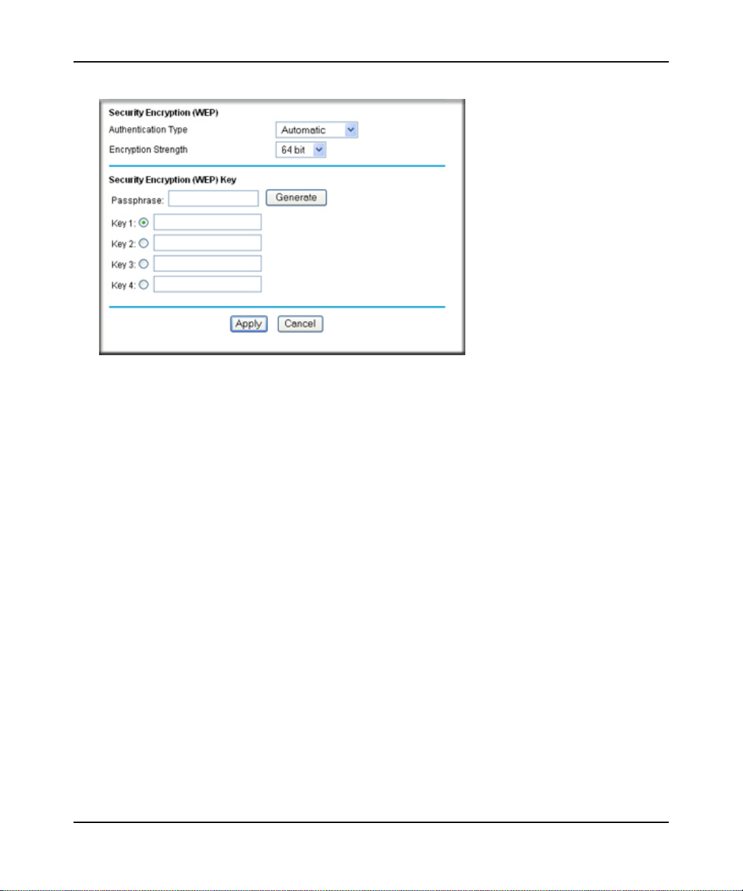
To configure WEP data encryption:
Note: If you use a wireless computer to configure WEP settings, you will be disconnected
when you click Apply. You must then either configure your wireless adapter to
match the WiFi router WEP settings or access the WiFi router from a wired
computer to make any further changes. Not all wireless adapter configuration
utilities support passphrase key generation.
1. Select Wireless Settings under Setup in the main menu.
2. In the Security Options section, select WEP. The WEP options display.
Safeguarding Your Network 2-9
May 2012
N300 WiFi Router (N300R) User Manual
.
Figure 2-3
3. Select the authentication type and encryption strength.
4. You can manually or automatically program the four data encryption keys. These values must
be identical on all computers and access points in your network.
• Automatic. In the Passphrase field, enter a word or group of printable characters, and
click Generate. The passphrase is case-sensitive. The four key fields are automatically
populated with key values.
• Manual. Enter 10 hexadecimal digits (any combination of 0–9, a–f, or A–F). These
entries are not case-sensitive. For example, AA is the same as aa.
Select which of the four keys to activate.
5. Click Apply to save your settings.
Configuring WPA-PSK and WPA2-PSK Wireless Security
Wi-Fi Protected Access with Pre-Shared Key (WPA-PSK and WPA2-PSK) data encryption
provides extremely strong data security, very effectively blocking eavesdropping. Because WPA
and WPA2 are relatively new standards, older wireless adapters and devices might not support
them. Check whether newer drivers are available from the manufacturer. Also, you might be able
to use the Push 'N' Connect feature to configure this type of security if it is supported by your
wireless clients. See “Using WPS Push Button Connect (Wi-Fi Protected Setup)” on page 2-13.
2-10 Safeguarding Your Network
v1.0, May 2012

N300 WiFi Router (N300R) User Manual
WPA–Pre-Shared Key does perform authentication. WPA-PSK uses TKIP (Temporal Key
Integrity Protocol) data encryption, and WPA2-PSK uses AES (Advanced Encryption Standard)
data encryption. Both methods dynamically change the encryption keys making them nearly
impossible to circumvent.
Mixed mode allows clients using either WPA-PSK (TKIP) or WPA2-PSK (AES). This provides
the most reliable security, and is easiest to implement, but it might not be compatible with older
adapters.
Note: Not all wireless adapters support WPA. Furthermore, client software is also
required. Windows XP with Service Pack 2 does include WPA support.
Nevertheless, the wireless adapter hardware and driver must also support WPA.
For instructions on configuring wireless computers or PDAs (personal digital
assistants) for WPA-PSK security, consult the documentation for the product you
are using.
To configure WPA-PSK, WPA2-PSK, or WPA-PSK+WPA2-PSK:
1. Select Wireless Settings under Setup in the main menu. The Wireless Settings screen
displays.
2. Select one of the WPA-PSK or WPA2-PSK options for the security type. The third option
(WPA-PSK [TKIP] + WP2-PSK [AES]) is the most flexible, since it allows clients using
either WPA-PSK or WPA2-PSK.
3. In the Passphrase field, enter a word or group of 8–63 printable characters. The passphrase is
case-sensitive.
Figure 2-4
4. Click Apply to save your settings.
Safeguarding Your Network 2-11
May 2012

N300 WiFi Router (N300R) User Manual
Viewing Advanced Wireless Settings
This section describes the wireless settings that you can view and specify in the Advanced
Wireless Settings screen, which you access under Advanced in the main menu.
To configure the advanced wireless security settings of your router:
1. Log in to the router as described in “Logging In To Your WiFi Router” on page 1-1.
2. Select Advanced Wireless Settings under Advanced in the main menu. The advanced
Wireless Settings screen displays
Figure 2-5
The available settings in this screen are:
2-12 Safeguarding Your Network
v1.0, May 2012

N300 WiFi Router (N300R) User Manual
• Enable Wireless Router Radio. If you disable the wireless router radio, wireless devices
cannot connect to the N300R router. If you will not be using your wireless network for a
period of time, you can clear this check box and disable all wireless connectivity.
• Fragmentation Length, CTS/RTS Threshold, Preamble Mode and Transmit Power
Control. The Fragmentation Threshold, CTS/RTS Threshold, Preamble Mode, and
Transmit Power Control options are reserved for wireless testing and advanced
configuration only. Do not change these settings.
• WPS Settings. For information about these settings, see the section, “Using WPS Push
Button Connect (Wi-Fi Protected Setup)” on page 2-13.
• Wireless Card Access List. For information about this list, see “Restricting Wireless
Access by MAC Address” on page 2-19.
.
Using WPS Push Button Connect (Wi-Fi Protected Setup)
If your wireless clients support Wi-Fi Protected Setup (WPS), you can use this feature to configure
the router’s network name (SSID) and security settings and, at the same time, connect a wireless
client securely and easily to the router. Look for the WPS push button on the rear panel of your
client device. WPS automatically configures the network name (SSID) and wireless security
settings for the router (if the router is in its default state) and broadcasts these settings to the
wireless client.
Note: On Networks’s WPS push button Connect feature is based on the Wi-Fi Protected
Setup (WPS) standard (for more information, see http://www.wi-fi.org). All other
Wi-Fi-certified and WPS-capable products should be compatible with On
Networks products that implement Push 'N' Connect or WPS push button Connect.
When you add wireless clients, whether or not they are WPS enabled, the added devices must
share the same network name (SSID) and security passphrase. For more information, see
“Connecting Additional Wireless Client Devices after WPS Setup” on page 2-18.
Note: If you choose to use WPS, the only security methods supported are WPA-PSK and
WPA2-PSK. WEP security is not supported by WPS.
The N300R router provides two methods for connecting to a wireless client that supports WPS,
described in the following sections:
Safeguarding Your Network 2-13
May 2012

N300 WiFi Router (N300R) User Manual
• “Push Button Configuration””
• “Security PIN Entry” on page 2-15
Push Button Configuration
There are two methods to enable a wireless client to join a network using a push button on the
router: using the physical push button or using the software button in the Add WPS Client screen.
Using the Physical Push Button
1. Press the WPS push button on the N300R router for over 5 seconds.
The WPS LED begins to blink in a regular pattern. While the light is blinking, you have 2
minutes to enable WPS on the client that you are trying to connect to the router.
2. On the wireless client, follow its specific networking instructions to enable WPS, to allow it to
connect to the router.
The N300R router’s WPS LED ceases blinking and remains on when one of these conditions
occurs:
• The router and the client establish a wireless connection.
• The 2-minute window period expires for establishing a WPS connection. If the connection
is not established, no WPS security settings will be specified in the N300R router.
Using the Software Button in the Add WPS Client Screen
1. Log in to the router as described in “Logging In To Your WiFi Router” on page 1-1.
2. Select Add WPS Client in the main menu, and click Next.
3. Select the Push Button setup method.
Figure 2-6
2-14 Safeguarding Your Network
v1.0, May 2012

N300 WiFi Router (N300R) User Manual
4. Click the button in the Add WPS Client screen. The Connecting to New Wireless Client
screen displays.
Figure 2-7
The WPS LED on the N300R router begins to blink in a regular pattern. While the button light
is blinking, you have 2 minutes to enable WPS on the device you are trying to connect to the
router.
5. In the wireless client, follow its specific networking instructions to enable WPS, to allow it to
connect to the router.
The N300R router’s WPS LED ceases blinking and remains on when one of these conditions
occurs:
• The router and the client establish a wireless connection.
• The 2-minute window period expires for establishing a WPS connection. If the connection
is not established, no WPS security settings will be specified in the N300R router.
Security PIN Entry
There are two ways to enable a wireless client to join a network using a PIN: using the router’s
security PIN or using the wireless client’s security PIN.
Using the Router’s Security PIN
1. Obtain your router’s security PIN from the rear panel of the router or from the Advanced
Wireless Settings screen.
2. On the wireless client, follow its specific networking instructions to enter the router’s security
PIN and to establish a wireless connection with the router.
Using the Wireless Client’s Security PIN
1. Log in to the router as described in “Logging In To Your WiFi Router” on page 1-1.
Safeguarding Your Network 2-15
May 2012

N300 WiFi Router (N300R) User Manual
2. Select Add WPS Client in the main menu, and click Next.
3. Select the PIN Number setup method.
Figure 2-8
4. On the wireless client, obtain its security PIN, or follow its specific networking instructions to
generate a client security PIN.
5. In the Add WPS Client screen of the N300R router, enter the client security PIN in the Enter
Client’s PIN field.
6. Click Next. The following screen displays, and the Smart Wizard initiates the wireless
connection:
Figure 2-9
2-16 Safeguarding Your Network
v1.0, May 2012

N300 WiFi Router (N300R) User Manual
Configuring the WPS Settings
1. Log in to the router as described in “Logging In To Your WiFi Router” on page 1-1.
2. Select Wireless Settings under Advanced in the main menu.
Figure 2-10
These options are available under WPS Settings:
• Router’s PIN. The PIN is displayed so that you can use it to configure the router through
WPS (Wi-Fi Protected Setup). It is also displayed on the router’s label.
• Disable Router’s PIN. If the router’s PIN is disabled, you cannot configure the router’s
wireless settings with WPS. However, if your settings are already configured, you can still
add WPS-enabled wireless clients. The router might disable the PIN if it detects
suspicious attempts to break into your wireless settings; this can happen if the check box is
selected. You can enable the PIN by clearing the check box and clicking Apply.
• Keep Existing Wireless Settings. This check box is automatically selected after WPS is
enabled to prevent unwanted settings changes, and is also selected if you have already
specified wireless security settings or your SSID without using WPS. When this check
box is not selected, adding a new wireless client using the push button or the Add WPS
Client screen (see “Push Button Configuration” on page 2-14) changes the router’s SSID
and security passphrase. You might need to clear it if you are using certain registrars, such
as for a Windows Vista PC, to configure the router through WPS.
Safeguarding Your Network 2-17
May 2012

N300 WiFi Router (N300R) User Manual
Connecting Additional Wireless Client Devices after WPS Setup
You can add WPS-enabled and non-WPS-enabled client devices.
Adding Additional WPS-Enabled Clients
To add an additional wireless client device that is WPS enabled:
Note: Your wireless settings do not change when you add an additional WPS-enabled
client unless you have cleared the Keep Existing Wireless Settings check box (in
the Wireless Settings screen). If you do clear the check box, a new SSID and a
passphrase are generated, and all existing connected wireless clients are
disassociated and disconnected from the router.
1. Follow the procedures in “Push Button Configuration” on page 2-14 or “Security PIN Entry”
on page 2-15.
2. For information about how to view a list of all devices connected to your router (including
wireless and Ethernet-connected), see “Viewing a List of Attached Devices” on page 6-7.
Adding Additional Non-WPS-Enabled Clients
If you are connecting a combination of WPS-enabled clients and clients that are not WPS enabled,
you cannot use the WPS setup procedures to add clients that are not WPS enabled.
To connect both non-WPS-enabled and WPS-enabled clients to the N300R router:
1. Configure the settings of the N300R router (shown in the Wireless Settings screen) for WPAPSK or WPA2-PSK security, and record that information. See “Configuring WPA-PSK and
WPA2-PSK Wireless Security” on page 2-10.
When you change security settings, all existing connected wireless clients that do not share
those settings are disassociated and disconnected from the router.
2. For the non-WPS-enabled devices that you wish to connect, open the networking utility, and
follow the utility’s instructions to enter security settings.
3. For the WPS-enabled devices that you wish to connect, follow the procedures in “Using WPS
Push Button Connect (Wi-Fi Protected Setup)” on page 2-13.
The N300R router automatically preserves the settings you configured in step 1 so all clients
share the same security settings (for more information, see “Configuring the WPS Settings” on
page 2-17).
2-18 Safeguarding Your Network
v1.0, May 2012

N300 WiFi Router (N300R) User Manual
4. For information about how to view a list of all devices connected to your router (including
wireless and Ethernet connected), see “Viewing a List of Attached Devices” on page 6-7.
Restricting Wireless Access by MAC Address
When a Wireless Card Access List is configured and enabled, the router checks the MAC address
of any wireless device attempting a connection and allows only connections to computers
identified on the trusted computers list.
The Wireless Card Access List displays a list of wireless computers that you allow to connect to
the router based on their MAC addresses. These wireless computers must also have the correct
SSID and wireless security settings to access the wireless router.
The MAC address is a network device’s unique 12-character physical address, containing the
hexadecimal characters 0–9, a–f, or A–F only, and separated by colons (for example,
00:09:AB:CD:EF:01). It can usually be found on the bottom of the wireless card or network
interface device. If you do not have access to the physical label, you can display the MAC address
using the network configuration utilities of the computer. In WindowsXP, for example, typing the
ipconfig/all command in an MSDOS command prompt window displays the MAC address as
Physical Address. You might also find the MAC addresses in the router’s Attached Devices screen.
To restrict access based on MAC addresses:
1. Select Wireless Settings under Advanced in the main menu.
2. In the Advanced Wireless Settings screen, click Setup Access List to display the Wireless
Card Access List.
Figure 2-11
Safeguarding Your Network 2-19
May 2012

N300 WiFi Router (N300R) User Manual
3. Click Add to add a wireless device to the wireless access control list. The Wireless Card
Access Setup screen opens and displays a list of currently active wireless cards and their
Ethernet MAC addresses.
Figure 2-12
4. If the computer you want appears in the Available Wireless Cards list, you can select the radio
button of that computer to capture its MAC address; otherwise, you can manually enter a name
and the MAC address of the authorized computer. You can usually find the MAC address on
the bottom of the wireless device.
Tip: You can copy and paste the MAC addresses from the router’s Attached Devices
screen into the MAC Address field of this screen. To do this, configure each
wireless computer to obtain a wireless link to the router. The computer should
then appear in the Attached Devices screen.
5. Click Add to add this wireless device to the Wireless Card Access List. The screen changes
back to the list screen.
6. Repeat step 3 through step 5 for each additional device you want to add to the list.
2-20 Safeguarding Your Network
v1.0, May 2012

N300 WiFi Router (N300R) User Manual
7. Select the Turn Access Control On check box.
Note: When configuring the router from a wireless computer whose MAC address is
not in the Trusted PC list, if you select Turn Access Control On, you lose
your wireless connection when you click Apply. You must then access the
WiFi router from a wired computer or from a wireless computer that is on the
access control list to make any further changes.
8. Click Apply to save your Wireless Card Access List settings.
Now, only devices on this list can wirelessly connect to the N300R router.
Warning: MAC address filtering adds an obstacle against unwanted access to your
network by the general public. However, because your trusted MAC
addresses appear in your wireless transmissions, an intruder can read them
and impersonate them. Do not rely on MAC address filtering alone to
secure your network.
Changing the Administrator Password
The default password for the router’s Web Configuration Manager is password. On Networks
recommends that you change this password to a more secure password.
Tip: Before changing the router password, back up your configuration settings with the
default password of password. If you save the settings with a new password, and
then you later forget the new password, you will have to reset the router back to the
factory defaults, and log in using the default password of password. This means you
will have to re-enter all the router configuration settings. For information about how
to back up your settings, see “Backing Up and Restoring the Configuration” on
page 6-8.
Safeguarding Your Network 2-21
May 2012

N300 WiFi Router (N300R) User Manual
To change the administrator password:
1. On the main menu, under Maintenance, select Set Password to display the Set Password
screen.
Figure 2-13
2. To change the password, first enter the old password, then enter the new password twice.
3. Click Apply.
Backing Up Your Configuration
The configuration settings of the N300R router are stored within the router in a configuration file.
You can back up (save) this file and retrieve it later. On Networks recommends that you save your
configuration file after you complete the configuration. If the router fails or becomes corrupted, or
an administrator password is lost, you can easily re-create your configuration by restoring the
configuration file.
For instructions on saving and restoring your configuration file, see “Managing the Configuration
File” on page 6-7.
Tip: Before saving your configuration file, change the administrator password to the
default, password. Then change it again after you have saved the configuration file.
If you save the file with a new password, and then you later forget the new
password, you will have to reset the router back to the factory defaults and log in
using the default password of password. This means you will have to re-enter all the
router configuration settings.
2-22 Safeguarding Your Network
v1.0, May 2012

N300 WiFi Router (N300R) User Manual
Live Parental Controls
On Networks Live Parental Controls, powered by OpenDNS, is a router-based Web filtering
solution available on On Networks Wireless-N router and gateway products. Designed to protect
you from identity theft and scams, Live Parental Controls blocks up to 50 categories of Internet
content.
Live Parental Controls protects all Internet-connected devices through the router. It protects not
only computers, but also set-top boxes, iPhones, iPods, and gaming consoles that are attached to
your network. Default and per-user settings allow you to customize configurations for different
computing arrangements and personalize the settings for each person. Per-time settings allow
Internet access during scheduled time slots.
Live Parental Controls requires a one-time installation of the management utility. Once set up,
Live Parental Controls runs in the background and does not interfere with normal Internet usage.
Download Live Parental Controls from this website: http://www.On Networks.com/lpc.
Understanding Your Firewall
Your N300 WiFi Router (N300R) contains a true firewall to protect your network from attacks and
intrusions. A firewall is a device that protects one network from another while allowing
communication between the two. Using a process called Stateful Packet Inspection, the firewall
analyzes all inbound and outbound traffic to determine whether or not it will be allowed to pass
through.
By default, the firewall allows any outbound traffic and prohibits any inbound traffic except for
responses to your outbound traffic. However, you can modify the firewall’s rules to achieve the
following behavior:
• Blocking sites. Block access from your network to certain Web locations based on Web
addresses and Web address keywords. This feature is described in “Blocking Access to
Internet Sites” on page 3-1.
• Blocking services. Block the use of certain Internet services by specific computers on your
network. This feature is described in “Blocking Access to Internet Services” on page 3-3.
• Scheduled blocking. Block sites and services according to a daily schedule. This feature is
described in “Scheduling Blocking” on page 3-5.
Safeguarding Your Network 2-23
May 2012

N300 WiFi Router (N300R) User Manual
• Allow inbound access to your server. To allow inbound access to resources on your local
network (for example, a Web server or remote desktop program), you can open the needed
services by configuring port forwarding as described in “Allowing Inbound Connections to
Your Network” on page 5-1.
• Allow certain games and applications to function correctly. Some games and applications
need to allow additional inbound traffic in order to function. Port triggering can dynamically
allow additional service connections, as described in “Configuring Port Triggering” on
page 5-10. Another feature to solve application conflicts with the firewall is Universal Plug
and Play (UPnP), described in “Using Universal Plug and Play” on page 5-14.
2-24 Safeguarding Your Network
v1.0, May 2012

Chapter 3
Restricting Access From Your Network
This chapter describes how to use the content filtering and reporting features of the N300 WiFi
Router (N300R) to protect your network.
This chapter includes the following sections:
• “Content Filtering Overview”
• “Blocking Access to Internet Sites”
• “Blocking Access to Internet Services” on page 3-3
• “Scheduling Blocking” on page 3-5
• “Viewing Logs of Web Access or Attempted Web Access” on page 3-6
• “Configuring E-mail Alert and Web Access Log Notifications” on page 3-8
Content Filtering Overview
The N300 WiFi Router (N300R) provides you with Web content filtering options, plus browser
activity reporting and instant alerts through e-mail. Parents and network administrators can
establish restricted access policies based on time of day, Web addresses, and Web address
keywords. You can also block Internet access by applications and services, such as chat rooms or
games.
Blocking Access to Internet Sites
The N300R router allows you to restrict access based on Web addresses and Web address
keywords. Up to 255 entries are supported in the Keyword list.
Keyword application examples:
• If the keyword XXX is specified, the URL www.zzzyyqq.com/xxx.html is blocked.
• If the keyword .com is specified, only websites with other domain suffixes (such as .edu, .org,
or .gov) can be viewed.
To block access to Internet sites:
3-1
v1.0, May 2012

N300 WiFi Router (N300R) User Manual
1. Select Block Sites under Content Filtering in the main menu. The Block Sites screen displays.
Figure 3-1
2. Enable keyword blocking by selecting either Per Schedule or Always.
To block by schedule, be sure to specify a time period in the Schedule screen. For information
about scheduling, see “Scheduling Blocking” on page 3-5.
Block all access to Internet browsing during a scheduled period by entering a dot (.) as the
keyword, and then set a schedule in the Schedule screen.
3. Add a keyword or domain by entering it in the keyword field and clicking Add Keyword. The
keyword or domain name then appears the Block sites containing these keywords or domain
names list.
Delete a keyword or domain name by selecting it from the list and clicking Delete Keyword.
4. You can specify one trusted user, which is a computer that is exempt from blocking and
logging. Specify a trusted user by entering that computer’s IP address in the Trusted IP
Address fields.
Since the trusted user is identified by IP address, you should configure that computer with a
fixed IP address.
3-2 Restricting Access From Your Network
May 2012

N300 WiFi Router (N300R) User Manual
5. Click Apply to save all your settings in the Block Sites screen.
Blocking Access to Internet Services
The N300R router allows you to block the use of certain Internet services by computers on your
network. This is called service blocking or port filtering. Services are functions performed by
server computers at the request of client computers. For example, Web servers serve Web pages,
time servers serve time and date information, and game hosts serve data about other players’
moves. When a computer on your network sends a request for service to a server computer on the
Internet, the requested service is identified by a service or port number. This number appears as the
destination port number in the transmitted IP packets. For example, a packet that is sent with
destination port number 80 is an HTTP (Web server) request.
To block access to Internet services:
1. Select Block Services under Content Filtering in the main menu. The Block Services screen
displays.
Figure 3-2
2. Enable service blocking by selecting either Per Schedule or Always, and then click Apply.
To block by schedule, be sure to specify a time period in the Schedule screen. For information
about scheduling, see “Scheduling Blocking” on page 3-5.
Restricting Access From Your Network 3-3
v1.0, May 2012

N300 WiFi Router (N300R) User Manual
3. Specify a service for blocking by clicking Add. The Block Services Setup screen displays.
Figure 3-3
4. From the Service Type list, select the application or service to be allowed or blocked. The list
already displays several common services, but you are not limited to these choices. To add any
additional services or applications that do not already appear, select User Defined. To define a
service, first you must determine which port number or range of numbers is used by the
application. The service port numbers for many common protocols are defined by the Internet
Engineering Task Force (IETF) and published in RFC1700, “Assigned Numbers.” Service
numbers for other applications are typically chosen from the range 1024 to 65535 by the
authors of the application. You can often determine port number information by contacting the
publisher of the application, by asking user groups or newsgroups, or by searching.
– Enter the starting port and ending port numbers. If the application uses a single port
number, enter that number in both fields.
– If you know that the application uses either TCP or UDP, select the appropriate protocol. If
you are not sure, select Both.
5. Select the radio button for the IP address configuration you want to block, and then enter the
IP addresses in the appropriate fields.
6. Click Add to enable your Block Services Setup selections.
3-4 Restricting Access From Your Network
May 2012

N300 WiFi Router (N300R) User Manual
Blocking Services by IP Address Range
In the Filter Services For area, you can block the specified service for a single computer, a range of
computers (having consecutive IP addresses), or all computers on your network.
Scheduling Blocking
The N300R router allows you to specify when blocking is enforced.
To schedule blocking:
1. Select Schedule under Content Filtering in the main menu. The Schedule screen displays.
Figure 3-4
Restricting Access From Your Network 3-5
v1.0, May 2012

N300 WiFi Router (N300R) User Manual
2. Configure the schedule for blocking keywords and services.
a. Days to Block. Select days on which you want to apply blocking by selecting the
appropriate check boxes. Select Every Day to select the check boxes for all days. Click
Apply.
b. Time of Day to Block. Select a start and end time in 24-hour format. Select All Day for
24-hour blocking. Click Apply.
Be sure to select your time zone in the E-mail screen as described in “” on page 3-9.
3. So that log entries are correctly time-stamped and sent at the correct time, be sure to set the
time as described in the next section.
4. Click Apply to save your settings.
Setting the Time Zone
The N300R router uses the Network Time Protocol (NTP) to obtain the current time and date from
one of several network time servers on the Internet. Localize the time zone so that your log entries
and other router functions include the correct time stamp.
To verify and set the time zone (see Figure 3-4 on page 3-5):
• Time Zone. To select your local time zone, use the drop-down list. This setting is used for the
blocking schedule and for time-stamping log entries.
• Automatically Adjust for Daylight Savings Time. If your region supports daylight savings
time, select this check box. The router will automatically adjust the time at the start and end of
the daylight savings time period.
Viewing Logs of Web Access or Attempted Web Access
The log is a detailed record of the websites you have accessed or attempted to access. Up to
128 entries are stored in the log. Log entries appear only when keyword blocking is enabled and no
log entries are made for the trusted user.
3-6 Restricting Access From Your Network
May 2012

N300 WiFi Router (N300R) User Manual
Select Logs under Content Filtering in the main menu. The Logs screen displays.
Figure 3-5
Table 3-1 describes the log entries.
Table 3-1. Log Entry Descriptions
Field Description
Date and time The date and time the log entry was recorded.
Source IP The IP address of the initiating device for this log entry.
Target address The name or IP address of the website or newsgroup
visited or to which access was attempted.
Action Whether the access was blocked or allowed.
Restricting Access From Your Network 3-7
v1.0, May 2012

N300 WiFi Router (N300R) User Manual
To include any of the checked items at the bottom of the screen in the log display, click Apply. You
can check as many or as few of these items as you wish.
To refresh the log screen, click the Refresh button.
To clear the log entries, click the Clear Log button.
To e-mail the log immediately, click the Send Log button.
Configuring E-mail Alert and Web Access Log Notifications
To receive logs and alerts by e-mail, you must provide your e-mail account information.
To configure e-mail alert and web access log notifications:
1. Select E-mail under Content Filtering in the main menu. The E-mail screen displays.
Figure 3-6
3-8 Restricting Access From Your Network
May 2012

N300 WiFi Router (N300R) User Manual
2. To receive e-mail logs and alerts from the router, select the Turn E-mail Notification On
check box.
a. Enter the name of your ISP’s outgoing (SMTP) mail server (such as mail.myISP.com) in
the Your Outgoing Mail Server field. You might be able to find this information in the
configuration screen of your e-mail program. If you leave this field blank, log and alert
messages will not be sent by e-mail.
b. Enter the e-mail address to which logs and alerts are sent in the Send To This E-mail
Address field. This e-mail address will also be used as the From address. If you leave this
field blank, log and alert messages will not be sent by e-mail.
3. If your e-mail server requires authentication, select the My Mail Server requires
authentication check box.
a. Enter your user name for the e-mail server in the User Name field.
b. Enter your password for the e-mail server in the Password field.
4. You can specify that logs are automatically sent by e-mail with these options:
• Send alert immediately. Select this check box for immediate notification of attempted
access to a blocked site or service.
• Send Logs According to this Schedule. Specifies how often to send the logs: Hourly,
Daily, Weekly, or When Full.
– Day. Specifies which day of the week to send the log. Relevant when the log is sent
weekly or daily.
– Time. Specifies the time of day to send the log. Relevant when the log is sent daily or
weekly.
If you select the Weekly, Daily, or Hourly option and the log fills up before the specified
period, the log is automatically e-mailed to the specified e-mail address. After the log is sent,
the log is cleared from the router’s memory. If the router cannot e-mail the log file, the log
buffer might fill up. In this case, the router overwrites the log and discards its contents.
5. Click Apply to save your settings.
Restricting Access From Your Network 3-9
v1.0, May 2012

N300 WiFi Router (N300R) User Manual
3-10 Restricting Access From Your Network
May 2012

Chapter 4
Customizing Your Network Settings
This chapter describes how to configure advanced networking features of the
N300 WiFi Router (N300R), including LAN, WAN, and routing settings.
It contains the following sections:
• “Using the LAN IP Setup Options”
• “Using a Dynamic DNS Service” on page 4-6
• “Configuring the WAN Setup Options” on page 4-8
• “Configuring Static Routes” on page 4-10
• “Wireless Repeating (Also Called WDS)” on page 4-13
Using the LAN IP Setup Options
The LAN Setup screen allows configuration of LAN IP services such as Dynamic Host
Configuration Protocol (DHCP) and Routing Information Protocol (RIP).
v1.0, May 2012
4-1

N300 WiFi Router (N300R) User Manual
To configure LAN IP settings, select LAN Setup under Advanced in the main menu. The LAN
Setup screen displays.
Figure 4-1
Configuring a Device Name
The device name is a user-friendly name for the router. This name is shown in the Network on
Windows Vista and the Network Explorer on all Windows systems. The Device Name field cannot
be blank. The default name is N300R.
4-2 Customizing Your Network Settings
May 2012

N300 WiFi Router (N300R) User Manual
Configuring LAN TCP/IP Setup Parameters
These are advanced settings that you might configure if you are a network administrator and your
network contains multiple routers. The router is shipped preconfigured to use private IP addresses
on the LAN side and to act as a DHCP server (see “Using the Router as a DHCP Server” on
page 4-4).
Note: If you change the LAN IP address of the router while connected through the
browser, you will be disconnected. You must then open a new connection to the
new IP address and log in again.
The router’s default LAN IP configuration is:
• LAN IP address. 192.168.1.1
• Subnet mask. 255.255.255.0
These addresses are part of the designated private address range for use in private networks and
should be suitable for most applications. If your network has a requirement to use a different IP
addressing scheme, you can make those changes in this screen.
The LAN IP settings are:
• IP Address. The LAN IP address of the router.
• IP Subnet Mask. The LAN subnet mask of the router. Combined with the IP address, the IP
subnet mask allows a device to know which other addresses are local to it, and which must be
reached through a gateway or router.
• RIP Direction. RIP allows a router to exchange routing information with other routers. The
RIP Direction selection controls how the router sends and receives RIP packets. Both is the
default.
– When set to Both or In Only, the router incorporates the RIP information that it receives.
– When set to Both or Out Only, the router broadcasts its routing table periodically.
• RIP Version. This controls the format and the broadcasting method of the RIP packets sent by
the router. (It recognizes both formats when receiving.) The default setting is Disabled.
– RIP-1 is universally supported. RIP-1 is usually adequate unless you have an unusual
network setup.
– RIP-2B carries more information than RIP-1 and uses subnet broadcasting.
– RIP-2M carries more information than RIP-1 and uses multicasting.
Customizing Your Network Settings 4-3
May 2012

N300 WiFi Router (N300R) User Manual
Using the Router as a DHCP Server
By default, the router functions as a DHCP server, allowing it to assign IP, DNS server, and default
gateway addresses to all computers connected to the router’s LAN. The assigned default gateway
address is the LAN address of the router. The router assigns IP addresses to the attached computers
from a pool of addresses specified in this screen. Each pool address is tested before it is assigned to
avoid duplicate addresses on the LAN.
Note: For most applications, the default DHCP and TCP/IP settings of the router are
satisfactory. Click the link to the online document “TCP/IP Networking Basics” in
Appendix B for an explanation of DHCP and information about how to assign IP
addresses for your network.
To specify a pool of IP addresses to be assigned, set the starting IP address and ending IP address.
These addresses should be part of the same IP address subnet as the router’s LAN IP address.
Using the default addressing scheme, you should define a range between 192.168.1.2 and
192.168.1.254, although you might wish to save part of the range for devices with fixed addresses.
The router delivers the following parameters to any LAN device that requests DHCP:
• An IP address from the range you have defined
• Subnet mask
• Gateway IP address (the router’s LAN IP address)
• Primary DNS server (if you entered a primary DNS address in the Basic Settings screen;
otherwise, the router’s LAN IP address)
• Secondary DNS server (if you entered a secondary DNS address in the Basic Settings screen)
To use another device on your network as the DHCP server, or to manually specify the network
settings of all of your computers, clear the Use Router as DHCP Server check box. Otherwise,
leave it selected. If this service is not selected and no other DHCP server is available on your
network, you need to set your computers’ IP addresses manually or they will not be able to access
the router.
4-4 Customizing Your Network Settings
May 2012

N300 WiFi Router (N300R) User Manual
Using Address Reservation
When you specify a reserved IP address for a computer on the LAN, that computer always
receives the same IP address each time it accesses the router’s DHCP server. Reserved IP
addresses should be assigned to computers or servers that require permanent IP settings.
Figure 4-2
To reserve an IP address:
1. Click Add.
2. In the IP Address field, enter the IP address to assign to the computer or server. (Choose an IP
address from the router’s LAN subnet, such as 192.168.1.x.)
3. Enter the MAC address of the computer or server.
Tip: If the computer is already present on your network, you can copy its MAC
address from the Attached Devices screen and paste it here.
4. Click Apply to enter the reserved address into the table.
Note: The reserved address is not assigned until the next time the computer contacts
the router’s DHCP server. Reboot the computer or access its IP configuration
and force a DHCP release and renew.
To edit or delete a reserved address entry:
1. Click the button next to the reserved address you want to edit or delete.
2. Click Edit or Delete.
Customizing Your Network Settings 4-5
May 2012

N300 WiFi Router (N300R) User Manual
Using a Dynamic DNS Service
If your Internet Service Provider (ISP) gave you a permanently assigned IP address, you can
register a domain name and have that name linked with your IP address by public Domain Name
Servers (DNS). However, if your Internet account uses a dynamically assigned IP address, you do
not know in advance what your IP address will be, and the address can change frequently. In this
case, you can use a commercial Dynamic DNS service, which allows you to register your domain
to their IP address, and forwards traffic directed at your domain to your frequently changing IP
address.
Note: If your ISP assigns a private WAN IP address (such as 192.168.x.x or 10.x.x.x), the
Dynamic DNS service will not work because private addresses are not routed on
the Internet.
Your router contains a client that can connect to the Dynamic DNS service provided by
DynDNS.org. You must first visit their website at www.dyndns.org and obtain an account and host
name, which you specify in the router. Then, whenever your ISP-assigned IP address changes,
your router automatically contacts the Dynamic DNS service provider, logs in to your account, and
registers your new IP address. If your host name is hostname, for example, you can reach your
router at hostname.dyndns.org.
Select Dynamic DNS under Advanced in the main menu. The Dynamic DNS screen displays.
Figure 4-3
4-6 Customizing Your Network Settings
May 2012

N300 WiFi Router (N300R) User Manual
To configure for a Dynamic DNS service:
1. Register for an account with one of the Dynamic DNS service providers whose names appear
in the Service Provider list. For example, for DynDNS.org, select www.dynDNS.org.
2. Select the Use a Dynamic DNS Service check box.
3. Select the name of your Dynamic DNS service provider.
4. Enter the host name (or domain name) that your Dynamic DNS service provider gave you.
5. Enter the user name for your Dynamic DNS account. This is the name that you use to log in to
your account, not your host name.
6. Enter the password (or key) for your Dynamic DNS account.
7. If your Dynamic DNS provider allows the use of wildcards in resolving your URL, you can
select the Use Wildcards check box to activate this feature.
For example, the wildcard feature causes *.yourhost.dyndns.org to be aliased to the same IP
address as yourhost.dyndns.org.
8. Click Apply to save your configuration.
Customizing Your Network Settings 4-7
May 2012

N300 WiFi Router (N300R) User Manual
Configuring the WAN Setup Options
The WAN Setup options let you disable port scan and DoS protection, configure a DMZ
(demilitarized zone) server, enable the WiFi router to respond to a ping on the WAN (Internet)
port, enable IGMP proxying, and change the Maximum Transmit Unit (MTU) size. Select WAN
Setup under Advanced in the main menu. The WAN Setup screen displays.
Figure 4-4
Disabling Port Scan and DoS Protection
The Stateful Packet Inspection (SPI) firewall protects your network and computers against attacks
and intrusions. A stateful packet firewall carefully inspects incoming traffic packets, looking for
known exploits such as malformed, oversized, or out-of-sequence packets. The firewall should be
disabled only in special circumstances, such as when you are troubleshooting application issues.
Setting Up a Default DMZ Server
The default DMZ server feature is helpful when you are using some online games and
videoconferencing applications that are incompatible with Network Address Translation (NAT).
The router is programmed to recognize some of these applications and to work correctly with
4-8 Customizing Your Network Settings
May 2012

N300 WiFi Router (N300R) User Manual
them, but there are other applications that might not function well. In some cases, one local
computer can run the application correctly if that computer’s IP address is entered as the default
DMZ server.
Warning: DMZ servers pose a security risk. A computer designated as the default DMZ
server loses much of the protection of the firewall, and is exposed to exploits
from the Internet. If compromised, the DMZ server computer can be used to
attack other computers on your network.
Incoming traffic from the Internet is usually discarded by the router unless the traffic is a response
to one of your local computers or a service that you have configured in the Port Forwarding/Port
Triggering screen. Instead of discarding this traffic, you can have it forwarded to one computer on
your network. This computer is called the default DMZ server.
The WAN Setup screen lets you configure a default DMZ server.
To assign a computer or server to be a default DMZ server:
1. Select the Default DMZ Server check box.
2. In the Default DMZ Server fields, enter the IP address for that computer or server.
3. Click Apply.
Responding to a Ping on the Internet (WAN) Port
If you want the router to respond to a ping from the Internet, select the Respond to Ping on
Internet Port check box. This should be used only as a diagnostic tool, since it allows your router
to be discovered by Internet scanners. Do not select this check box unless you have a specific
reason to do so, such as when troubleshooting your connection.
Enabling IGMP Proxying
IGPM (Internet Group Management Protocol) proxying is disabled by default. When IGPM
Proxying is enabled, the WAN IGMP server treats your router as an IGMP client; for LAN
devices, such as set-up boxes or PCs, the router acts as an IGMP server. The IGMP Proxying
function lets a LAN device receive the multicast traffic it is interested in from the Internet.
Customizing Your Network Settings 4-9
May 2012

N300 WiFi Router (N300R) User Manual
Setting the MTU Size
The normal MTU value for most Ethernet networks is 1500 bytes, 1492 bytes for PPPoE
connections, or 1450 for PPTP connections. For some ISPs, you might need to reduce the MTU
size, but this is rarely required and should not be done unless you are sure it is necessary for your
ISP connection. For more information, see “Changing the MTU Size” on page 5-16.
To change the MTU size:
1. In the MTU Size field, enter a new size between 64 and 1500.
2. Click Apply to save the new configuration.
Configuring NAT Filtering
Network Address Translation (NAT) determines how the router processes inbound traffic. Secured
NAT provides a secured firewall to protect the computers on the LAN from attacks from the
Internet, but might prevent some Internet games, point-to-point applications, or multimedia
applications from functioning. Open NAT provides a much less secured firewall, but allows almost
all Internet applications to function. For more information about NAT, see “How Your Computer
Accesses a Remote Computer through Your Router” on page 5-2.
To change the NAT option:
1. In the NAT Filtering area, select either the Secured or the Open radio button.
2. Click Apply to save the new configuration.
Configuring Static Routes
Static routes provide additional routing information to your router. Under usual circumstances, the
router has adequate routing information after it has been configured for Internet access, and you do
not need to configure additional static routes. You must configure static routes only for unusual
cases such as multiple routers or multiple IP subnets located on your network.
As an example of when a static route is needed, consider the following case:
• Your primary Internet access is through a cable modem to an ISP.
• You have an ISDN router on your home network for connecting to the company where you are
employed. This router’s address on your LAN is 192.168.1.100.
• Your company’s network address is 134.177.0.0.
4-10 Customizing Your Network Settings
May 2012

N300 WiFi Router (N300R) User Manual
When you first configured your router, two implicit static routes were created. A default route was
created with your ISP as the gateway, and a second static route was created to your local network
for all 192.168.1.x addresses. With this configuration, if you attempt to access a device on the
134.177.0.0 network, your router forwards your request to the ISP. The ISP forwards your request
to the company where you are employed, and the request is likely to be denied by the company’s
firewall.
In this case you must define a static route, telling your router that 134.177.0.0 should be accessed
through the ISDN router at 192.168.1.100.
In this example:
• The Destination IP Address and IP Subnet Mask fields specify that this static route applies
to all 134.177.x.x addresses.
• The Gateway IP Address field specifies that all traffic for these addresses should be
forwarded to the ISDN router at 192.168.1.100.
•A Metric value of 1 will work since the ISDN router is on the LAN.
• Private is selected only as a precautionary security measure in case RIP is activated.
To add or edit a static route:
1. Select Static Routes under Advanced in the main menu. The Static Routes screen displays.
Figure 4-5
Customizing Your Network Settings 4-11
May 2012

N300 WiFi Router (N300R) User Manual
2. Click Add to expand the Static Routes screen.
Figure 4-6
3. In the Route Name field, enter a name for this static route. (This is for identification purposes
only.)
4. Select the Private check box if you want to limit access to the LAN only. If Private is selected,
the static route is not reported in RIP.
5. Select the Active check box to make this route effective.
6. In the Destination IP Address field, enter the IP address of the final destination.
7. In the IP Subnet Mask field, enter the IP subnet mask for this destination.
If the destination is a single host, enter 255.255.255.255.
8. In the Gateway IP Address field, enter the gateway IP address, which must be a router on the
same LAN segment as the N300R router.
9. In the Metric field, enter a number between 1 and 15 as the metric value.
This represents the number of routers between your network and the destination. Usually, a
setting of 2 or 3 works, but if this is a direct connection, set it to 1.
10. Click Apply to have the static route entered into the table.
4-12 Customizing Your Network Settings
May 2012

N300 WiFi Router (N300R) User Manual
Wireless Repeating (Also Called WDS)
The N300R router can be used with a wireless access point (AP) to build large bridged wireless
networks. Wireless repeating is a type of Wireless Distribution System (WDS).
Warning: If you use the wireless repeating function, your options for wireless security
are limited to None or WEP. For more information about wireless security, see
Chapter 2, “Safeguarding Your Network.”
The following figure shows a wireless repeating scenario:
Repeater AP
Base Station AP
Figure 4-7
To set up a wireless network using WDS,
he following conditions must be met for both APs:
• Both APs must use the same SSID, wireless channel, and encryption mode (see “Choosing
Appropriate Wireless Security” on page 2-1 or “Using WPS Push Button Connect (Wi-Fi
Protected Setup)” on page 2-13).
• Both APs must be on the same LAN IP subnet. That is, all the AP LAN IP addresses are in the
same network.
• All LAN devices (wired and wireless computers) must be configured to operate in the same
LAN network address range as the APs.
• If you make changes in the Wireless Settings screen, click Apply so that they take effect.
Customizing Your Network Settings 4-13
May 2012

N300 WiFi Router (N300R) User Manual
Wireless Repeating Function
You can view or change wireless repeater settings for the WiFi router. From the main menu of the
browser interface, under Advanced, click Wireless Repeating Function to display the Wireless
Repeating Function screen.
Figure 4-8
The WiFi router supports two modes of the wireless repeating function, and allows you to control
wireless client association:
• Wireless Repeater. The WiFi router sends all traffic from its local wireless or wired
computers to a remote AP. To configure this mode, you must know the MAC address of the
remote parent AP.
• Wireless Base Station. The WiFi router acts as the parent AP, bridging traffic to and from the
child repeater AP, as well as handling wireless and wired local computers. To configure this
mode, you must know the MAC addresses of the child repeater AP.
• Disable Wireless Client Association. Usually this check box is cleared so that the router is an
access point for wireless computers.
If this check box is selected, the router communicates wirelessly only with other APs whose
MAC addresses are listed in this screen. The router still communicates with wire-connected
LAN devices.
4-14 Customizing Your Network Settings
May 2012

N300 WiFi Router (N300R) User Manual
Setting Up the Base Station
The wireless repeating function works only in hub and spoke mode. The units cannot be daisy
chained. You must know the wireless settings for both units. You must know the MAC address of
the remote unit. First, set up the base station, and then set up the repeater.
To set up the base station:
1. Set up both units with exactly the same wireless settings (SSID, mode, channel, and security).
Note that the wireless security option must be set to None or WEP.
2. Log into the WiFi router base unit, under the Advanced heading, select Wireless Repeating
Function to display the Wireless Repeating Function screen.
Figure 4-9
3. Select the Enable Wireless Repeating Function check box and the Wireless Base Station
radio button.
4. Enter the MAC address for the repeater units.
5. Click Apply to save your changes.
Customizing Your Network Settings 4-15
May 2012

N300 WiFi Router (N300R) User Manual
Setting Up a Repeater Unit
Use a wired Ethernet connection to set up the repeater unit to avoid conflicts with the wireless
connection to the base station.
Note: If you are using the N300R base station with a non-On Networks WiFi router as the
repeater, you might need to change additional configuration settings. In particular,
you should disable the DHCP server function on the wireless repeater AP.
To configure a N300R router as a repeater unit:
1. If you are using the same model of WiFi router for both the base station and repeaters, you
must change the LAN IP address for each repeater to a different IP address in the same subnet
(see “Using the LAN IP Setup Options” on page 4-1).
Note: Failing to change the LAN IP address will cause an IP address conflict in the
network because the factory default LAN IP is the same for both units.
2. Log in to the router that will be the repeater. Check the Wireless Settings screen, and verify
that the wireless settings match the base station exactly. If the settings are different, be sure to
configure the wireless settings to match the base station settings (see “Setting Up and Testing
Basic Wireless Connectivity” on page 1-11).
3. In the Wireless Repeating Function screen, select the Enable Wireless Repeating Function
check box and the Wireless Repeater radio button.
4. Fill in the IP Address field. This IP address must be in the same subnet as the base station, but
different from the LAN IP of the base station.
5. Fill in the Base Station MAC Address field.
6. Click Apply to save your changes.
7. Verify connectivity across the LANs.
A computer on any wireless or wired LAN segment of the WiFi router should be able to
connect to the Internet or share files and printers with any other wireless or wired computer or
server connected to the other AP.
4-16 Customizing Your Network Settings
May 2012

Chapter 5
Fine-Tuning Your Network
This chapter describes how to modify the configuration of the N300 WiFi Router (N300R) to
allow specific applications to access the Internet or to be accessed from the Internet, and how to
make adjustments to enhance your network’s performance.
This chapter includes the following sections:
• “Allowing Inbound Connections to Your Network”
• “Configuring Port Forwarding to Local Servers” on page 5-6
• “Configuring Port Triggering” on page 5-10
• “Using Universal Plug and Play” on page 5-14
• “Optimizing Wireless Performance” on page 5-15
• “Changing the MTU Size” on page 5-16
• “Quality of Service” on page 5-18
• “Overview of Home and Small Office Networking Technologies” on page 5-24
Allowing Inbound Connections to Your Network
By default, the N300R router blocks any inbound traffic from the Internet to your computers
except for replies to your outbound traffic. However, you might need to create exceptions to this
rule for the following purposes:
• To allow remote computers on the Internet to access a server on your local network.
• To allow certain applications and games to work correctly when their replies are not
recognized by your router.
Your router provides two features for creating these exceptions: port forwarding and port
triggering. This section explains how a normal outbound connection works, followed by two
examples explaining how port forwarding and port triggering operate and how they differ.
5-1
May 2012

N300 WiFi Router (N300R) User Manual
How Your Computer Accesses a Remote Computer through Your Router
When a computer on your network needs to access a computer on the Internet, your computer
sends your router a message containing source and destination address and process information.
Before forwarding your message to the remote computer, your router must modify the source
information and must create and track the communication session so that replies can be routed
back to your computer.
Here is an example of normal outbound traffic and the resulting inbound responses:
1. You open Internet Explorer, beginning a browser session on your computer. Invisible to you,
your operating system assigns a service number (port number) to every communication
process running on your computer. In this example, let’s say Windows assigns port number
5678 to this browser session.
2. You ask your browser to get a Web page from the Web server at www.example.com. Your
computer composes a Web page request message with the following address and
port information:
• The source address is your computer’s IP address.
• The source port number is 5678, the browser session.
• The destination address is the IP address of www.example.com, which your computer
finds by asking a DNS server.
• The destination port number is 80, the standard port number for a Web server process.
Your computer then sends this request message to your router.
3. Your router creates an entry in its internal session table describing this communication session
between your computer and the Web server at www.example.com. Before sending the Web
page request message to www.example.com, your router stores the original information and
then modifies the source information in the request message, performing Network Address
Translation (NAT):
• The source address is replaced with your router’s public IP address.
This is necessary because your computer uses a private IP address that is not globally
unique and cannot be used on the Internet.
• The source port number is changed to a number chosen by the router, such as 33333. This
is necessary because two computers could independently be using the same session
number.
Your router then sends this request message through the Internet to the Web server at
www.example.com.
5-2 Fine-Tuning Your Network
v1.0, May 2012

N300 WiFi Router (N300R) User Manual
4. The Web server at www.example.com composes a return message with the requested Web
page data. The return message contains the following address and port information:
• The source address is the IP address of www.example.com.
• The source port number is 80, the standard port number for a Web server process.
• The destination address is the public IP address of your router.
• The destination port number is 33333.
The Web server then sends this reply message to your router.
5. Upon receiving the incoming message, your router checks its session table to determine
whether there is an active session for port number 33333. Finding an active session, the router
then modifies the message, restoring the original address information replaced by NAT. The
message now contains the following address and port information:
• The source address is the IP address of www.example.com.
• The source port number is 80, the standard port number for a Web server process.
• The destination address is your computer’s IP address.
• The destination port number is 5678, the browser session that made the initial request.
Your router then sends this reply message to your computer, which displays the Web page
from www.example.com.
6. When you finish your browser session, your router eventually senses a period of inactivity in
the communications. Your router then removes the session information from its session table,
and incoming traffic is no longer accepted on port number 33333.
How Port Triggering Changes the Communication Process
In the preceding example, requests are sent to a remote computer by your router from a particular
service port number, and replies from the remote computer to your router are directed to that port
number. If the remote server sends a reply back to a different port number, your router will not
recognize it and will discard it. However, some application servers (such as FTP and IRC servers)
send replies back to multiple port numbers. Using the port triggering function of your router, you
can tell the router to open additional incoming ports when a particular outgoing port originates
a session.
An example is Internet Relay Chat (IRC). Your computer connects to an IRC server at destination
port 6667. The IRC server not only responds to your originating source port, but also sends an
“identify” message to your computer on port 113. Using port triggering, you can tell the router,
Fine-Tuning Your Network 5-3
May 2012

N300 WiFi Router (N300R) User Manual
“When you initiate a session with destination port 6667, you must also allow incoming traffic on
port 113 to reach the originating computer.” Using steps similar to the preceding example, the
following sequence shows the effects of the port triggering rule you have defined:
1. You open an IRC client program, beginning a chat session on your computer.
2. Your IRC client composes a request message to an IRC server using a destination port number
of 6667, the standard port number for an IRC server process. Your computer then sends this
request message to your router.
3. Your router creates an entry in its internal session table describing this communication session
between your computer and the IRC server. Your router stores the original information,
performs Network Address Translation (NAT) on the source address and port, and sends this
request message through the Internet to the IRC server.
4. Noting your port triggering rule, and having observed the destination port number of 6667,
your router creates an additional session entry to send any incoming port 113 traffic to your
computer.
5. The IRC server sends a return message to your router using the NAT-assigned source port (as
in the previous example, let’s say port 33333) as the destination port. The IRC server also
sends an “identify” message to your router with destination port 113.
6. Upon receiving the incoming message to destination port 33333, your router checks its session
table to determine whether there is an active session for port number 33333. Finding an active
session, the router restores the original address information replaced by NAT and sends this
reply message to your computer.
7. Upon receiving the incoming message to destination port 113, your router checks its session
table and learns that there is an active session for port 113, associated with your computer. The
router replaces the message’s destination IP address with your computer’s IP address and
forwards the message to your computer.
8. When you finish your chat session, your router eventually senses a period of inactivity in the
communications. The router then removes the session information from its session table, and
incoming traffic is no longer accepted on port numbers 33333 or 113.
To configure port triggering, you need to know which inbound ports the application needs. Also,
you need to know the number of the outbound port that will trigger the opening of the inbound
ports. You can usually determine this information by contacting the publisher of the application, or
user groups or newsgroups.
Note: Only one computer at a time can use the triggered application.
5-4 Fine-Tuning Your Network
v1.0, May 2012

N300 WiFi Router (N300R) User Manual
How Port Forwarding Changes the Communication Process
In both of the preceding examples, your computer initiates an application session with a server
computer on the Internet. However, you might need to allow a client computer on the Internet to
initiate a connection to a server computer on your network. Normally, your router ignores any
inbound traffic that is not a response to your own outbound traffic. You can configure exceptions
to this default rule by using the port forwarding feature.
A typical application of port forwarding can be shown by reversing the client-server relationship
from our previous Web server example. In this case, a remote computer’s browser needs to access
a Web server running on a computer in your local network. Using port forwarding, you can tell the
router, “When you receive incoming traffic on port 80 (the standard port number for a Web server
process), forward it to the local computer at 192.168.1.123.” The following sequence shows the
effects of the port forwarding rule you have defined:
1. The user of a remote computer opens Internet Explorer and requests a Web page from
www.example.com, which resolves to the public IP address of your router. The remote
computer composes a Web page request message with the following destination information:
• The destination address is the IP address of www.example.com, which is the address of
your router.
• The destination port number is 80, the standard port number for a Web server process.
The remote computer then sends this request message through the Internet to your router.
2. Your router receives the request message and looks in its rules table for any rules covering the
disposition of incoming port 80 traffic. Your port forwarding rule specifies that incoming port
80 traffic should be forwarded to local IP address 192.168.1.123. Therefore, your router
modifies the destination information in the request message:
The destination address is replaced with 192.168.1.123.
Your router then sends this request message to your local network.
3. Your Web server at 192.168.1.123 receives the request and composes a return message with
the requested Web page data. Your Web server then sends this reply message to your router.
4. Your router performs Network Address Translation (NAT) on the source IP address, and sends
this request message through the Internet to the remote computer, which displays the Web
page from www.example.com.
To configure port forwarding, you need to know which inbound ports the application needs. You
usually can determine this information by contacting the publisher of the application or user
groups or newsgroups.
Fine-Tuning Your Network 5-5
May 2012

N300 WiFi Router (N300R) User Manual
How Port Forwarding Differs from Port Triggering
The following points summarize the differences between port forwarding and port triggering:
• Port triggering can be used by any computer on your network, although only one computer can
use it at a time.
• Port forwarding is configured for a single computer on your network.
• Port triggering does not need to know the computer’s IP address in advance. The IP address is
captured automatically.
• Port forwarding requires that you specify the computer’s IP address during configuration, and
the IP address must never change.
• Port triggering requires specific outbound traffic to open the inbound ports, and the triggered
ports are closed after a period of no activity.
• Port forwarding is always active and does not need to be triggered.
Configuring Port Forwarding to Local Servers
Using the port forwarding feature, you can allow certain types of incoming traffic to reach servers
on your local network. For example, you might make a local Web server, FTP server, or game
server visible and available to the Internet.
Use the Port Forwarding screen to configure the router to forward specific incoming protocols to
computers on your local network. In addition to servers for specific applications, you can also
specify a default DMZ server to which all other incoming protocols are forwarded. The DMZ
server is configured in the WAN Setup screen, as discussed in “Setting Up a Default DMZ Server”
on page 4-8.
Before starting, you need to determine which type of service, application, or game you will
provide, and the local IP address of the computer that will provide the service. Be sure the
computer’s IP address never changes.
Tip: To ensure that your server computer always has the same IP address, use the
reserved IP address feature of your N300R router. See “Using Address Reservation”
on page 4-5 for instructions on how to use reserved IP addresses.
5-6 Fine-Tuning Your Network
v1.0, May 2012

N300 WiFi Router (N300R) User Manual
To configure port forwarding to a local server:
1. Select Port Forwarding/Port Triggering under Advanced in the main menu. The Port
Forwarding/Port Triggering screen displays.
Figure 5-1
2. From the Service Name list, select the service or game that you will host on your network.
If the service does not appear in the list, see the following section, “Adding a Custom
Service.”
3. In the corresponding Server IP Address fields, enter the last digit of the IP address of your
local computer that will provide this service.
4. To the right of Server IP Address, click Add. The service appears in the list in the screen.
Adding a Custom Service
To define a service, game, or application that does not appear in the Service Name list, you must
first determine which port number or range of numbers is used by the application. You can usually
determine this information by contacting the publisher of the application or user groups or
newsgroups. When you have the port number information, follow these steps:
1. Select Port Forwarding/Port Triggering under Advanced in the main menu.
Fine-Tuning Your Network 5-7
May 2012

N300 WiFi Router (N300R) User Manual
2. Click Add Custom Service (see Figure 5-1 on page 5-7).The Ports–Custom Services screen
displays.
Figure 5-2
3. In the Service Name field, enter a descriptive name.
4. In the Service Type field, select the protocol. If you are unsure, select TCP/UDP.
5. In the Starting Port field, enter the beginning port number.
• If the application uses only a single port, enter the same port number in the Ending Port
field.
• If the application uses a range of ports, enter the ending port number of the range in the
Ending Port field.
6. In the Server IP Address field, enter the IP address of your local computer that will provide
this service.
7. Click Apply. The service appears in the list in the Port Forwarding/Port Triggering screen.
5-8 Fine-Tuning Your Network
v1.0, May 2012

N300 WiFi Router (N300R) User Manual
Editing or Deleting a Port Forwarding Entry
To edit or delete a port forwarding entry:
1. In the table, select the button next to the service name.
Figure 5-3
2. Click Edit Service or Delete Service to make changes.
3. Click Apply.
Application Example: Making a Local Web Server Public
If you host a Web server on your local network, you can use port forwarding to allow Web requests
from anyone on the Internet to reach your Web server.
To make a local Web server public:
1. Assign your Web server either a fixed IP address or a dynamic IP address using DHCP address
reservation, as explained in “Using Address Reservation” on page 4-5. In this example, your
router will always give your Web server an IP address of 192.168.1.33.
2. In the Port Forwarding screen, configure the router to forward the HTTP service to the local
address of your Web server at 192.168.1.33.
HTTP (port 80) is the standard protocol for Web servers.
3. (Optional) Register a host name with a Dynamic DNS service, and configure your router to
use the name as described in “Using a Dynamic DNS Service” on page 4-6.
To access your Web server from the Internet, a remote user must know the IP address that has
been assigned by your ISP. However, if you use a Dynamic DNS service, the remote user can
reach your server by a user-friendly Internet name, such as myOn Networks.dyndns.org.
Fine-Tuning Your Network 5-9
May 2012

N300 WiFi Router (N300R) User Manual
Configuring Port Triggering
Port triggering is a dynamic extension of port forwarding that is useful in these cases:
• More than one local computer needs port forwarding for the same application (but not
simultaneously).
• An application needs to open incoming ports that are different from the outgoing port.
When port triggering is enabled, the router monitors outbound traffic looking for a specified
outbound “trigger” port. When the router detects outbound traffic on that port, it remembers the IP
address of the local computer that sent the data. The router then temporarily opens the specified
incoming port or ports, and forwards incoming traffic on the triggered ports to the triggering
computer.
While port forwarding creates a static mapping of a port number or range to a single local
computer, port triggering can dynamically open ports to any computer that needs them and can
close the ports when they are no longer needed.
Note: If you use applications such as multiplayer gaming, peer-to-peer connections, real-
time communications such as instant messaging, or remote assistance (a feature in
Windows XP), you should also enable Universal Plug and Play (UPnP) according
to the instructions in “Using Universal Plug and Play” on page 5-14.
To configure port triggering, you need to know which inbound ports the application needs. Also,
you need to know the number of the outbound port that will trigger the opening of the inbound
ports. You can usually determine this information by contacting the publisher of the application or
user groups or newsgroups.
To set up port triggering:
1. Select Port Forwarding/Port Triggering under Advanced in the main menu. The
Forwarding/Port Triggering screen displays (see Figure 5-1 on page 5-7).
5-10 Fine-Tuning Your Network
v1.0, May 2012

N300 WiFi Router (N300R) User Manual
2. Select the Port Triggering radio button. The port triggering information displays.
Figure 5-4
3. Clear the Disable Port Triggering check box.
Note: If the Disable Port Triggering check box is selected after you configure port
triggering, port triggering is disabled. However, any port triggering
configuration information you added to the router is retained even though it is
not used.
4. In the Port Triggering Timeout field, enter a value up to 9999 minutes. This value controls
the inactivity timer for the designated inbound ports. The inbound ports close when the
inactivity time expires. This is required because the router cannot be sure when the application
has terminated.
Fine-Tuning Your Network 5-11
May 2012

N300 WiFi Router (N300R) User Manual
5. Click Add Service. The Port Triggering–Services screen displays.
Figure 5-5
6. In the Service Name field, enter a descriptive service name.
7. In the Service User field, select Any (the default) to allow this service to be used by any
computer on the Internet. Otherwise, select Single address, and enter the IP address of one
computer to restrict the service to a particular computer.
8. Select the service type, either TCP or UDP.
9. In the Triggering Port field, enter the number of the outbound traffic port that will cause the
inbound ports to be opened.
10. Enter the inbound connection port information in the Connection Type, Starting Port, and
Ending Port fields.
5-12 Fine-Tuning Your Network
v1.0, May 2012

N300 WiFi Router (N300R) User Manual
11. Click Apply. The service appears in the Port Triggering Portmap table.
Figure 5-6
Fine-Tuning Your Network 5-13
May 2012

N300 WiFi Router (N300R) User Manual
Using Universal Plug and Play
Universal Plug and Play (UPnP) helps devices, such as Internet appliances and computers, to
access the network and connect to other devices as needed. UPnP devices can automatically
discover the services from other registered UPnP devices on the network.
Note: If you use applications such as multiplayer gaming, peer-to-peer connections, real-
time communications such as instant messaging, or remote assistance (a feature in
Windows XP), you should enable UPnP.
To turn on Universal Plug and Play:
1. Select UPnP under Advanced the main menu. The UPnP screen displays.
Figure 5-7
2. The available settings and information displayed in this screen are:
• Turn UPnP On. UPnP can be enabled or disabled for automatic device configuration. The
default setting for UPnP is disabled. If this check box is not selected, the router does not
allow any device to automatically control the resources, such as port forwarding
(mapping) of the router.
5-14 Fine-Tuning Your Network
v1.0, May 2012

N300 WiFi Router (N300R) User Manual
• Advertisement Period. The advertisement period is how often the router broadcasts its
UPnP information. This value can range from 1 to 1440 minutes. The default period is 30
minutes. Shorter durations ensure that control points have current device status at the
expense of additional network traffic. Longer durations might compromise the freshness
of the device status but can significantly reduce network traffic.
• Advertisement Time To Live. The time to live for the advertisement is measured in hops
(steps) for each UPnP packet sent. The time to live hop count is the number of steps a
broadcast packet is allowed to propagate for each UPnP advertisement before it
disappears. The number of hops can range from 1 to 255. The default value for the
advertisement time to live is 4 hops, which should be fine for most home networks. If you
notice that some devices are not being updated or reached correctly, then it might be
necessary to increase this value.
• UPnP Portmap Table. The UPnP Portmap Table displays the IP address of each UPnP
device that is currently accessing the router and which ports (Internal and External) that
device has opened. The UPnP Portmap Table also displays what type of port is open and
whether that port is still active for each IP address.
3. Click Apply to save your settings.
Optimizing Wireless Performance
The speed and operating distance or range of your wireless connection can vary significantly based
on the physical placement of the wireless router. You should choose a location for your router that
will maximize the network speed.
Note: Failure to follow these guidelines can result in significant performance degradation
or inability to wirelessly connect to the router.
The following list describes how to optimize wireless router performance.
• Identify critical wireless links.
If your network has several wireless devices, decide which wireless devices need the highest
data rate, and locate the router near them. Many wireless products have automatic data-rate
fallback, which allows increased distances without loss of connectivity. This also means that
devices that are farther away might be slower. Therefore, the most critical links in your
network are those where the traffic is high and the distances are great. Optimize those first.
Fine-Tuning Your Network 5-15
May 2012

N300 WiFi Router (N300R) User Manual
• Choose placement carefully.
For best results, place your router:
– Near the center of the area in which your computers will operate.
– In an elevated location such as a high shelf where the wirelessly connected computers
have line-of-sight access (even if through walls).
– Avoid obstacles to wireless signals.
– Keep wireless devices at least 2 feet from large metal fixtures such as file cabinets,
refrigerators, pipes, metal ceilings, reinforced concrete, and metal partitions.
– Keep away from large amounts of water such as fish tanks and water coolers.
• Reduce interference.
– Avoid windows unless communicating between buildings.
– Place wireless devices away from various electromagnetic noise sources, especially those
in the 2400–2500 MHz frequency band. Common noise-creating sources are:
• Computers and fax machines (no closer than 1 foot)
• Copying machines, elevators, and cell phones (no closer than 6 feet)
• Microwave ovens (no closer than 10 feet)
• Choose your settings.
– Use a scanning utility to determine what other wireless networks are operating nearby, and
choose an unused channel.
– Turn off SSID broadcast, and change the default SSID. Other nearby devices might
automatically try to connect to your network several times a second, which can cause
significant performance reduction.
• Use WMM to improve the performance of voice and video traffic over the wireless link.
Changing the MTU Size
The Maximum Transmission Unit (MTU) is the largest data packet a network device transmits.
When one network device communicates across the Internet with another, the data packets travel
through many devices along the way. If any device in the data path has a lower MTU setting than
the other devices, the data packets must be split or “fragmented” to accommodate the one with the
smallest MTU.
5-16 Fine-Tuning Your Network
v1.0, May 2012

N300 WiFi Router (N300R) User Manual
The best MTU setting for On Networks equipment is often just the default value, and changing the
value might fix one problem but cause another. Leave MTU unchanged unless one of these
situations occurs:
• You have problems connecting to your ISP, or other Internet service, and either the technical
support of the ISP or of On Networks recommends changing the MTU size. These might
require an MTU change:
– A secure Web site that will not open, or displays only part of a Web page
– Yahoo e-mail
– MSN
– America Online’s DSL service
• You use VPN and have severe performance problems.
• You used a program to optimize MTU for performance reasons, and now you have
connectivity or performance problems.
Note: An incorrect MTU setting can cause Internet communication problems such as the
inability to access certain Web sites, frames within Web sites, secure login pages,
or FTP or POP servers.
If you suspect an MTU problem, a common solution is to change the MTU size to 1400. If you are
willing to experiment, you can gradually reduce the MTU size from the maximum value of 1500
until the problem goes away. Table 5-1 describes common MTU sizes and applications.
Table 5-1. Common MTU Sizes
MTU Application
1500 The largest Ethernet packet size and the default value. This is the typical setting for non-
PPPoE, non-VPN connections, and is the default value for On Networks routers,
adapters, and switches.
1492 Used in PPPoE environments.
1472 Maximum size to use for pinging. (Larger packets are fragmented.)
1468 Used in some DHCP environments.
1460 Usable by AOL if you do not have large e-mail attachments, for example.
1436 Used in PPTP environments or with VPN.
1400 Maximum size for AOL DSL.
576 Typical value to connect to dial-up ISPs.
Fine-Tuning Your Network 5-17
May 2012

N300 WiFi Router (N300R) User Manual
To change the MTU size:
1. In the main menu, under Advanced, select WAN Setup.
2. In the MTU Size field, enter a new size between 64 and 1500.
3. Click Apply to save the new configuration.
Quality of Service
Quality of Service (QoS) is an advanced feature that can be used to prioritize some types of traffic
ahead of others. The N300R router can provide QoS prioritization over the wireless link.
Using WMM QoS for Wireless Multimedia Applications
The N300R router supports Wi-Fi Multimedia Quality of Service (WMM QoS) to prioritize
wireless voice and video traffic over the wireless link. WMM QoS provides prioritization of
wireless data packets from different applications based on four access categories: voice, video,
best effort, and background. For an application to receive the benefits of WMM QoS, both it and
the client running that application must be WMM enabled. Legacy applications that do not support
WMM, and applications that do not require QoS, are assigned to the best effort category, which
receives a lower priority than voice and video.
Configuring QoS for Internet Access
To specify prioritization of traffic, you must create a policy for the type of traffic and add the
policy to the QoS Policy table in the QoS Setup screen.
To create a QoS policy:
5-18 Fine-Tuning Your Network
v1.0, May 2012

N300 WiFi Router (N300R) User Manual
From the main menu of the browser interface, under Advanced, select QoS Setup. The QoS Setup
screen displays:
Figure 5-8
WMM QoS is enabled by default. You can disable it by clearing the Enable WMM check box and
clicking Apply.
QoS for Applications and Online Gaming
To create a QoS policy for traffic for specific applications or online games:
1. From the main menu of the browser interface, under Advanced, select QoS Setup. The QoS
Setup screen displays, as shown in Figure 5-8.
Fine-Tuning Your Network 5-19
May 2012

N300 WiFi Router (N300R) User Manual
2. Click Setup QoS rule. The QoS - Priority Rules screen displays.
Figure 5-9
For convenience, the QoS Policy table lists many common applications and online games that
can benefit from QoS handling.
5-20 Fine-Tuning Your Network
v1.0, May 2012

N300 WiFi Router (N300R) User Manual
3. Click Add Priority Rule. The QoS - Priority Rules screen displays.
Figure 5-10
4. In the Priority Category list, select either Applications or Online Gaming. In either case, a
list of predefined applications or games displays in the Applications drop-down list.
5. From the Applications list, you can select an existing item, or you can scroll to the bottom of
the list and select Add a New Application or Add a New Game.
a. If you chose to add a new entry, the screen expands as shown:
Figure 5-11
b. In the QoS Policy for field, enter a descriptive name for the new application or game.
c. Select the packet type, either TCP, UDP, or both (TCP/UDP), and specify the port
number or range of port numbers used by the application or game.
Fine-Tuning Your Network 5-21
May 2012

N300 WiFi Router (N300R) User Manual
6. From the Priority drop-down list, select the priority that this traffic should receive relative to
other applications and traffic when accessing the Internet. The options are Low, Normal, High,
and Highest.
7. Click Apply to save this rule to the QoS Policy list and return to the QoS Setup screen.
8. In the QoS Setup screen, select the Turn Internet Access QoS On check box.
9. Click Apply.
QoS for a Router LAN Port
To create a QoS policy for a device connected to one of the router’s LAN ports:
1. From the main menu, under Advanced, select QoS Setup. The QoS Setup screen displays, as
shown in Figure 5-8 on page 5-19.
2. Click Add Priority Rule.
3. From the Priority Category list, select Ethernet LAN Port. The QoS - Priority Rules screen
changes:
Figure 5-12
4. From the LAN port list, select the LAN port that will have a QoS policy.
5. From the Priority drop-down list, select the priority that this port’s traffic should receive
relative to other applications and traffic when accessing the Internet. The options are Low,
Normal, High, and Highest.
6. Click Apply to save this rule to the QoS Policy list and return to the QoS Setup screen.
7. In the QoS Setup screen, select the Turn Internet Access QoS On check box.
8. Click Apply.
5-22 Fine-Tuning Your Network
v1.0, May 2012

N300 WiFi Router (N300R) User Manual
QoS for a MAC Address
To create a QoS policy for traffic from a specific MAC address:
1. From the main menu, under Advanced, select QoS Setup. The QoS Setup screen displays, as
shown in Figure 5-8 on page 5-19.
2. Click Add Priority Rule.
3. From the Priority Category list, select MAC Address. The QoS - Priority Rules screen
changes:
Figure 5-13
4. If the device to be prioritized appears in the MAC Device List, select it. The information from
the MAC Device List is used to populate the policy name, MAC Address, and Device Name
fields. If the device does not appear in the MAC Device List, click Refresh. If it still does not
appear, you must complete these fields manually.
5. From the Priority drop-down list, select the priority that this device’s traffic should receive
relative to other applications and traffic when accessing the Internet. The options are Low,
Normal, High, and Highest.
6. Click Apply to save this rule to the QoS Policy list and return to the QoS Setup screen.
7. In the QoS Setup screen, select the Turn Internet Access QoS On check box.
8. Click Apply.
Fine-Tuning Your Network 5-23
May 2012

N300 WiFi Router (N300R) User Manual
Editing or Deleting an Existing QoS Policy
To edit or delete an existing QoS policy:
1. From the main menu, under Advanced, select QoS Setup. The QoS Setup screen displays, as
shown in Figure 5-8 on page 5-19.
2. Select the radio button next to the QoS policy to be edited or deleted, and do one of the
following:
• Click Delete to remove the QoS policy.
• Click Edit to edit the QoS policy. Follow the instructions in the preceding sections to
change the policy settings.
3. Click Apply in the QoS Setup screen to save your changes.
Overview of Home and Small Office Networking Technologies
Common connection types and their speed and security considerations are:
• Broadband Internet. Your Internet connection speed is determined by your modem type,
such as ADSL or cable modem, as well as the connection speed of the sites to which you
connect, and general Internet traffic. ADSL and cable modem connections are asymmetrical,
meaning they have a lower data rate to the Internet (upstream) than from the Internet
(downstream). Keep in mind that when you connect to another site that also has an
asymmetrical connection, the data rate between your sites is limited by each side’s upstream
data rate. A typical residential ADSL or cable modem connection provides a downstream
throughput of about 1 to 3 megabits per second (Mbps). Newer technologies such as ADSL2+
and Fiber to the Home (FTTH) will increase the connection speed to tens of Mbps.
• Wireless. Your N300 WiFi Router (N300R) provides a wireless data throughput of up to 300
Mbps using technology called multiple input, multiple output (MIMO), in which multiple
antennas transmit multiple streams of data. The use of multiple antennas also provides
excellent range and coverage. With the introduction of the newer WPA and WPA2 encryption
and authentication protocols, wireless security is extremely strong.
5-24 Fine-Tuning Your Network
v1.0, May 2012

N300 WiFi Router (N300R) User Manual
To get the best performance, use RangeMax NEXT adapters such as the WN511B for your
computers. Although the RangeMax NEXT router is compatible with older 802.11b and
802.11g adapters, the use of these older wireless technologies in your network can result in
lower throughput overall (typically less than 10 Mbps for 802.11b and less than 40 Mbps for
802.11g). In addition, many older wireless products do not support the latest security
protocols, WPA and WPA2.
• Powerline. For connecting rooms or floors that are blocked by obstructions or are distant
vertically, consider networking over your building’s AC wiring. On Networks’s Powerline HD
family of products delivers up to 200 Mbps to any outlet, while the older-generation XE
family of products delivers 14 Mbps or 85 Mbps. Data transmissions are encrypted for
security, and you can configure an individual network password to prevent neighbors from
connecting.
The Powerline HD family of products can coexist on the same network with older-generation
XE family products or HomePlug 1.0 products, but they are not interoperable with these older
products.
• Wired Ethernet. As gigabit-speed Ethernet ports (10/100/1000 Mbps) become common on
newer computers, wired Ethernet remains a good choice for speed, economy, and security.
Gigabit Ethernet can extend up to 100 meters with twisted-pair wiring of Cat 5e or better. A
wired connection is not susceptible to interference, and eavesdropping would require a
physical connection to your network.
Note: Actual data throughput will vary. Network conditions and environmental factors,
including volume of network traffic, building materials and construction, and
network overhead, can lower actual data throughput rate.
Assessing Your Speed Requirements
Because your Internet connection is likely to operate at a much lower speed than your local
network, faster local networking technologies might not improve your Internet experience.
However, many emerging home applications require high data rates. For example:
• Streaming HD video requires 10 to 30 Mbps per stream. Because latency and packet loss can
disrupt your video, plan to provide at least twice the capacity you need.
• Streaming MP3 audio requires less than 1 Mbps per stream and does not strain most modern
networks. Like video, however, streaming audio is also sensitive to latency and packet loss, so
a congested network or a noisy link can cause problems.
Fine-Tuning Your Network 5-25
May 2012

N300 WiFi Router (N300R) User Manual
• Backing up computers over the network has become popular due to the availability of
inexpensive mass storage. Table 5-2 shows the time to transfer 1 gigabyte (1 GB) of data using
various networking technologies.
Table 5-2. Theoretical Transfer Time for 1 Gigabyte
Network Connection Theoretical Raw Transfer Time
Gigabit wired Ethernet 8 seconds
RangeMax NEXT Wireless-N 26 seconds
Powerline HD 40 seconds
100 Mbps wired Ethernet 80 seconds
802.11n wireless 45 seconds
802.11g wireless 150 seconds
802.11b wireless 700 seconds
10 Mbps wired Ethernet 800 seconds
Cable modem (3 Mbps) 2700 seconds
Analog modem (56 kbps) 144,000 seconds (40 hours)
5-26 Fine-Tuning Your Network
v1.0, May 2012

Chapter 6
Using Network Monitoring Tools
This chapter describes how to use the maintenance features of your N300 WiFi Router (N300R).
This chapter includes the following sections:
• “Viewing WiFi Router Status Information”
• “Viewing a List of Attached Devices” on page 6-7
• “Managing the Configuration File” on page 6-7
• “Updating the Router Firmware” on page 6-9
• “Enabling Remote Management Access” on page 6-13
• “Traffic Meter” on page 6-15
May 2012
6-1

N300 WiFi Router (N300R) User Manual
Viewing WiFi Router Status Information
To view router status and usage information:
1. Select Router Status under Maintenance in the main menu. The Router Status screen
displays.
Figure 6-1
6-2 Using Network Monitoring Tools
v1.0, May 2012

N300 WiFi Router (N300R) User Manual
Table 6-1 describes the router status fields.
Table 6-1. WiFi Router Status Fields
Field Description
Hardware Version The hardware version of the router.
Firmware Version The version of the current software installed in the router. This will
change if you update your router.
GUI Language Version The version of the selected GUI language for the router manager
screens.
Internet Port. The following settings apply to the Internet (WAN) port of the router.
MAC Address The Media Access Control address. This is the unique physical
address being used by the Internet (WAN) port of the router.
IP Address The IP address being used by the Internet (WAN) port of the router. If
no address is shown, or is 0.0.0.0, the router cannot connect to the
Internet.
DHCP If set to None, the router is configured to use a fixed IP address on
the WAN. If set to DHCP Client, the router is configured to obtain an
IP address dynamically from the ISP.
IP Subnet Mask The IP subnet mask being used by the Internet (WAN) port of the
router.
Domain Name Server The Domain Name Server addresses being used by the router. A
Domain Name Server translates human-language URLs such as
www.On Networks.com into IP addresses.
LAN Port. The following settings apply to the Ethernet (LAN) port of the router.
MAC Address The Media Access Control address. This is the unique physical
address being used by the LAN port of the router.
IP Address The IP address being used by the Ethernet (LAN) port of the router.
The default is 192.168.1.1.
DHCP Identifies whether the router’s built-in DHCP server is active for the
LAN-attached devices.
IP Subnet Mask The IP subnet mask being used by the Ethernet (LAN) port of the
router. The default is 255.255.255.0.
Using Network Monitoring Tools 6-3
May 2012

N300 WiFi Router (N300R) User Manual
Table 6-1. WiFi Router Status Fields (continued)
Field Description
Wireless Port. The following settings apply to the wireless port of the router.
Name (SSID) The wireless network name (SSID) being used by the wireless port of
the router. The default is On Networks.
Region The geographic region where the router is being used. It might be
illegal to use the wireless features of the router in some parts of the
world.
Channel Identifies the channel of the wireless port being used.
Mode Indicates the wireless communication mode:
• Up to 54 Mbps.
• Up to 145 Mbps.
• Up to 300 Mbps (in this mode, there are two channels: a primary
channel [P] and a secondary channel [S]).
Wireless AP Indicates whether the radio feature of the router is enabled. If not
enabled, the Wireless LED on the front panel is off.
Broadcast Name Indicates whether the router is broadcasting its SSID.
Wi-Fi Protected Setup Indicates whether the router’s PIN is enabled and whether the router
is configured for Push ‘N’ Connect (Wi-Fi Protected Setup). For more
information, see “Using WPS Push Button Connect (Wi-Fi Protected
Setup)” on page 2-13.
2. Click Connection Status to display the connection status.
Figure 6-2
6-4 Using Network Monitoring Tools
v1.0, May 2012
 Loading...