

Page 1
Optimizing Wireless Performance
The speed and operating distance or range of your wireless connection can vary significantly based
on the physical placement of the wireless router. You should choose a location for your router that
will maximize the network speed.
Note: Failure to follow these guidelines can result in significant performance degradation
or inability to wirelessly connect to the router. For complete range and
performance specifications, click the link to the online document “Wireless
Networking Basics” in Appendix B.
The following list describes how to optimize wireless router performance.
• Identify critical wireless links.
If your network has several wireless devices, decide which wireless devices need the highest
data rate, and locate the router near them. Many wireless products have automatic data-rate
fallback, which allows increased distances without loss of connectivity. This also means that
devices that are farther away might be slower. Therefore, the most critical links in your
network are those where the traffic is high and the distances are great. Optimize those first.
• Choose placement carefully.
For best results, place your router:
– Near the center of the area in which your computers will operate.
– In an elevated location such as a high shelf where the wirelessly connected computers
have line-of-sight access (even if through walls).
– Avoid obstacles to wireless signals.
– Keep wireless devices at least 2 feet from large metal fixtures such as file cabinets,
refrigerators, pipes, metal ceilings, reinforced concrete, and metal partitions.
– Keep away from large amounts of water such as fish tanks and water coolers.
• Reduce interference.
– Avoid windows unless communicating between buildings.
– Place wireless devices away from various electromagnetic noise sources, especially those
in the 2400–2500 MHz frequency band. Common noise-creating sources are:
• Computers and fax machines (no closer than 1 foot)
• Copying machines, elevators, and cell phones (no closer than 6 feet)
Fine-Tuning Your Network 5-14
v1.0, August 2010
Page 2

• Microwave ovens (no closer than 10 feet)
• Choose your settings.
– Use a scanning utility to determine what other wireless networks are operating nearby, and
choose an unused channel.
– Turn off SSID broadcast, and change the default SSID. Other nearby devices might
automatically try to connect to your network several times a second, which can cause
significant performance reduction.
• Use WMM to improve the performance of voice and video traffic over the wireless link.
Changing the MTU Size
The Maximum Transmission Unit (MTU) is the largest data packet a network device transmits.
When one network device communicates across the Internet with another, the data packets travel
through many devices along the way. If any device in the data path has a lower MTU setting than
the other devices, the data packets must be split or “fragmented” to accommodate the one with the
smallest MTU.
The best MTU setting for NETGEAR equipment is often just the default value, and changing the
value might fix one problem but cause another. Leave MTU unchanged unless one of these
situations occurs:
• You have problems connecting to your ISP, or other Internet service, and either the technical
support of the ISP or of NETGEAR recommends changing the MTU size. These might require
an MTU change:
– A secure Web site that will not open, or displays only part of a Web page
– Yahoo e-mail
– MSN
– America Online’s DSL service
• You use VPN and have severe performance problems.
• You used a program to optimize MTU for performance reasons, and now you have
connectivity or performance problems.
Note: An incorrect MTU setting can cause Internet communication problems such as the
inability to access certain Web sites, frames within Web sites, secure login pages,
or FTP or POP servers.
Fine-Tuning Your Network 5-15
v1.0, August 2010
Page 3

If you suspect an MTU problem, a common solution is to change the MTU size to 1400. If you are
willing to experiment, you can gradually reduce the MTU size from the maximum value of 1500
until the problem goes away. Table 5-1 describes common MTU sizes and applications.
Table 5-1. Common MTU Sizes
MTU Application
1500 The largest Ethernet packet size and the default value. This is the typical setting for non-
PPPoE, non-VPN connections, and is the default value for NETGEAR routers, adapters,
and switches.
1492 Used in PPPoE environments.
1472 Maximum size to use for pinging. (Larger packets are fragmented.)
1468 Used in some DHCP environments.
1460 Usable by AOL if you do not have large e-mail attachments, for example.
1436 Used in PPTP environments or with VPN.
1400 Maximum size for AOL DSL.
576 Typical value to connect to dial-up ISPs.
To change the MTU size:
1. In the main menu, under Advanced, select WAN Setup.
2. In the MTU Size field, enter a new size between 64 and 1500.
3. Click Apply to save the new configuration.
Overview of Home and Small Office Networking
Technologies
Common connection types and their speed and security considerations are:
• Broadband Internet. Your Internet connection speed is determined by your modem type,
such as ADSL or cable modem, as well as the connection speed of the sites to which you
connect, and general Internet traffic. ADSL and cable modem connections are asymmetrical,
meaning they have a lower data rate to the Internet (upstream) than from the Internet
(downstream). Keep in mind that when you connect to another site that also has an
asymmetrical connection, the data rate between your sites is limited by each side’s upstream
data rate. A typical residential ADSL or cable modem connection provides a downstream
throughput of about 1 to 3 megabits per second (Mbps). Newer technologies such as ADSL2+
and Fiber to the Home (FTTH) will increase the connection speed to tens of Mbps.
Fine-Tuning Your Network 5-16
v1.0, August 2010
Page 4
• Wireless. Your N 150 Wireless Router WNR1000 v2h2 provides a wireless data
throughput of up to 150 Mbps. With the introduction of the newer WPA and WPA2 encryption
and authentication protocols, wireless security is extremely strong.
To get the best performance, use RangeMax NEXT adapters such as the WN511B for your
computers. Although the WNR1000 v2h2 router is compatible with older 802.11b and 802.11g
adapters, the use of these older wireless technologies in your network can result in lower
throughput overall (typically less than 10 Mbps for 802.11b and less than 40 Mbps for
802.11g). In addition, many older wireless products do not support the latest security
protocols, WPA and WPA2.
• Powerline. For connecting rooms or floors that are blocked by obstructions or are distant
vertically, consider networking over your building’s AC wiring. NETGEAR’s Powerline HD
family of products delivers up to 200 Mbps to any outlet, while the older-generation XE
family of products delivers 14 Mbps or 85 Mbps. Data transmissions are encrypted for
security, and you can configure an individual network password to prevent neighbors from
connecting.
The Powerline HD family of products can coexist on the same network with older-generation
XE family products or HomePlug 1.0 products, but they are not interoperable with these older
products.
• Wired Ethernet. As gigabit-speed Ethernet ports (10/100/1000 Mbps) become common on
newer computers, wired Ethernet remains a good choice for speed, economy, and security.
Gigabit Ethernet can extend up to 100 meters with twisted-pair wiring of Cat 5e or better. A
wired connection is not susceptible to interference, and eavesdropping would require a
physical connection to your network.
Note: Actual data throughput will vary. Network conditions and environmental factors,
including volume of network traffic, building materials and construction, and
network overhead, can lower actual data throughput rate.
Assessing Your Speed Requirements
Because your Internet connection is likely to operate at a much lower speed than your local
network, faster local networking technologies might not improve your Internet experience.
However, many emerging home applications require high data rates. For example:
• Streaming HD video requires 10 to 30 Mbps per stream. Because latency and packet loss can
disrupt your video, plan to provide at least twice the capacity you need.
Fine-Tuning Your Network 5-17
v1.0,August 2010
Page 5

• Streaming MP3 audio requires less than 1 Mbps per stream and does not strain most modern
networks. Like video, however, streaming audio is also sensitive to latency and packet loss, so
a congested network or a noisy link can cause problems.
• Backing up computers over the network has become popular due to the availability of
inexpensive mass storage. Table 5-2 shows the time to transfer 1 gigabyte (1 GB) of data using
various networking technologies.
Table 5-2. Theoretical Transfer Time for 1 Gigabyte
Network Connection Theoretical Raw Transfer Time
Gigabit wired Ethernet 8 seconds
RangeMax NEXT Wireless-N 26 seconds
Powerline HD 40 seconds
100 Mbps wired Ethernet 80 seconds
802.11n wireless 45 seconds
802.11g wireless 150 seconds
802.11b wireless 700 seconds
10 Mbps wired Ethernet 800 seconds
Cable modem (3 Mbps) 2700 seconds
Analog modem (56 kbps) 144,000 seconds (40 hours)
Fine-Tuning Your Network 5-18
v1.0, August 2010
Page 6

Chapter 6
Using Network Monitoring Tools
This chapter describes how to use the maintenance features of your N 150 Wireless Router
WNR1000 v2h2.
This chapter includes the following sections:
• “Viewing Wireless Router Status Information”
• “Viewing a List of Attached Devices” on page 6-7
• “Managing the Configuration File” in Chapter 6
• “Updating the Router Firmware” on page 6-9
• “Enabling Remote Management Access” on page 6-12
• “Traffic Meter” on page 6-14
v1.0, August 2010
6-1
Page 7
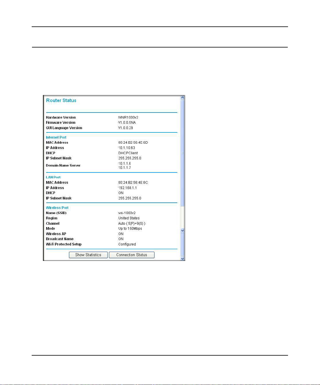
Viewing Wireless Router Status Information
To view router status and usage information:
1. Select Router Status under Maintenance in the main menu. The Router Status screen
displays.
Figure 6-1
Using Network Monitoring Tools 6-2
v1.0, August 2010
Page 8

Table 6-1 describes the router status fields.
Table 6-1. Wireless Router Status Fields
Field Description
Hardware Version The hardware version of the router.
Firmware Version The version of the current software installed in the router. This will
change if you update your router.
Internet Port. The following settings apply to the Internet (WAN) port of the router.
MAC Address The Media Access Control address. This is the unique physical
address being used by the Internet (WAN) port of the router.
IP Address The IP address being used by the Internet (WAN) port of the router. If
no address is shown, or is 0.0.0.0, the router cannot connect to the
Internet.
DHCP If set to None, the router is configured to use a fixed IP address on
the WAN. If set to DHCP Client, the router is configured to obtain an
IP address dynamically from the ISP.
IP Subnet Mask The IP subnet mask being used by the Internet (WAN) port of the
router. For an explanation of subnet masks and subnet addressing,
click the link to the online document “TCP/IP Networking Basics” in
Appendix B.
Domain Name Server The Domain Name Server addresses being used by the router. A
Domain Name Server translates human-language URLs such as
www.netgear.com into IP addresses.
LAN Port. The following settings apply to the Ethernet (LAN) port of the router.
MAC Address The Media Access Control address. This is the unique physical
address being used by the LAN port of the router.
IP Address The IP address being used by the Ethernet (LAN) port of the router.
The default is 192.168.1.1.
DHCP Identifies whether the router’s built-in DHCP server is active for the
LAN-attached devices.
IP Subnet Mask The IP subnet mask being used by the Ethernet (LAN) port of the
router. The default is 255.255.255.0.
Using Network Monitoring Tools 6-3
v1.0, August 2010
Page 9

Table 6-1. Wireless Router Status Fields (continued)
Field Description
Wireless Port. The following settings apply to the wireless port of the router.
Name (SSID) The wireless network name (SSID) being used by the wireless port of
the router. The default is NETGEAR.
Region The geographic region where the router is being used. It might be
illegal to use the wireless features of the router in some parts of the
world.
Channel Identifies the channel of the wireless port being used. Click the link to
the online document “Wireless Networking Basics” in Appendix B for
the frequencies used on each channel.
Mode Indicates the wireless communication mode:
• Up to 54 Mbps.
• Up to 65 Mbps.
• Up to 150 Mbps.
Wireless AP Indicates whether the radio feature of the router is enabled. If not
enabled, the Wireless LED on the front panel is off.
Broadcast Name Indicates whether the router is broadcasting its SSID.
Wi-Fi Protected Setup Indicates whether the router’s PIN is enabled and whether the router
is configured for Push ‘N’ Connect (Wi-Fi Protected Setup). For more
information, see “Using Push 'N' Connect (Wi-Fi Protected Setup)” on
page 2-13.
Using Network Monitoring Tools 6-4
v1.0, August 2010
Page 10
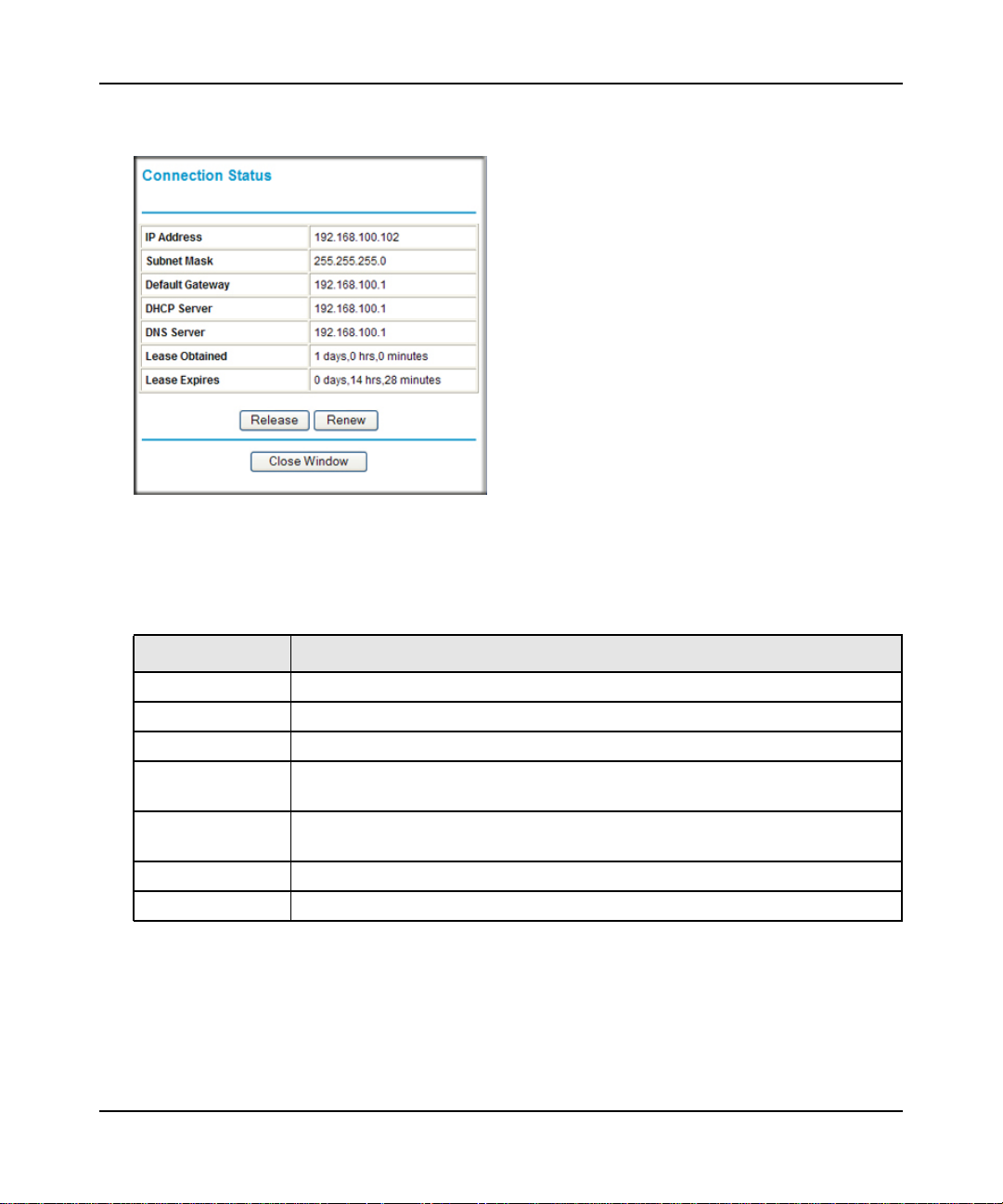
2. Click Connection Status to display the connection status.
Figure 6-2
Table 6-2 describes the connection status settings.
Table 6-2. Connection Status Settings
Item Description
IP Address The IP address that is assigned to the router.
Subnet Mask The subnet mask that is assigned to the router.
Default Gateway The IP address for the default gateway that the router communicates with.
DHCP Server The IP address for the Dynamic Host Configuration Protocol server that provides
the TCP/IP configuration for all the computers that are connected to the router.
DNS Server The IP address of the Domain Name Service server that provides translation of
network names to IP addresses.
Lease Obtained The date and time that the lease was obtained.
Lease Expires The date and time that the lease will expire.
a. Click the Release button to release the connection status items (that is, all items return to
0).
b. Click the Renew button to renew to the connection status items (that is, all items are
refreshed).
c. Click the Close Window button to close the Connection Status screen.
Using Network Monitoring Tools 6-5
v1.0, August 2010
Page 11
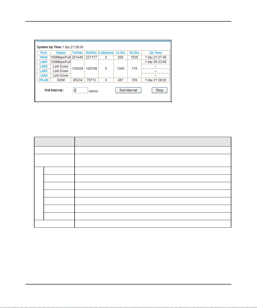
3. Click Show Statistics to display router usage statistics.
Figure 6-3
Table 6-3 describes the router statistics.
Table 6-3. Router Statistics
Item Description
System Up Time The time elapsed since the router was last restarted.
Port The statistics for the WAN (Internet) and LAN (Ethernet) ports. For each port, the
screen displays the following:
Status The link status of the port.
TxPkts The number of packets transmitted on this port since reset or manual clear.
RxPkts The number of packets received on this port since reset or manual clear.
Collisions The number of collisions on this port since reset or manual clear.
Tx B/s The current transmission (outbound) bandwidth used on the WAN and LAN ports.
Rx B/s The current reception (inbound) bandwidth used on the WAN and LAN ports.
Up Time The time elapsed since this port acquired the link.
Poll Interval The intervals at which the statistics are updated in this screen.
To change the polling frequency, enter a time in seconds in the Poll Interval field, and click
Set Interval.
To stop the polling entirely, click Stop.
Using Network Monitoring Tools 6-6
v1.0, August 2010
Page 12
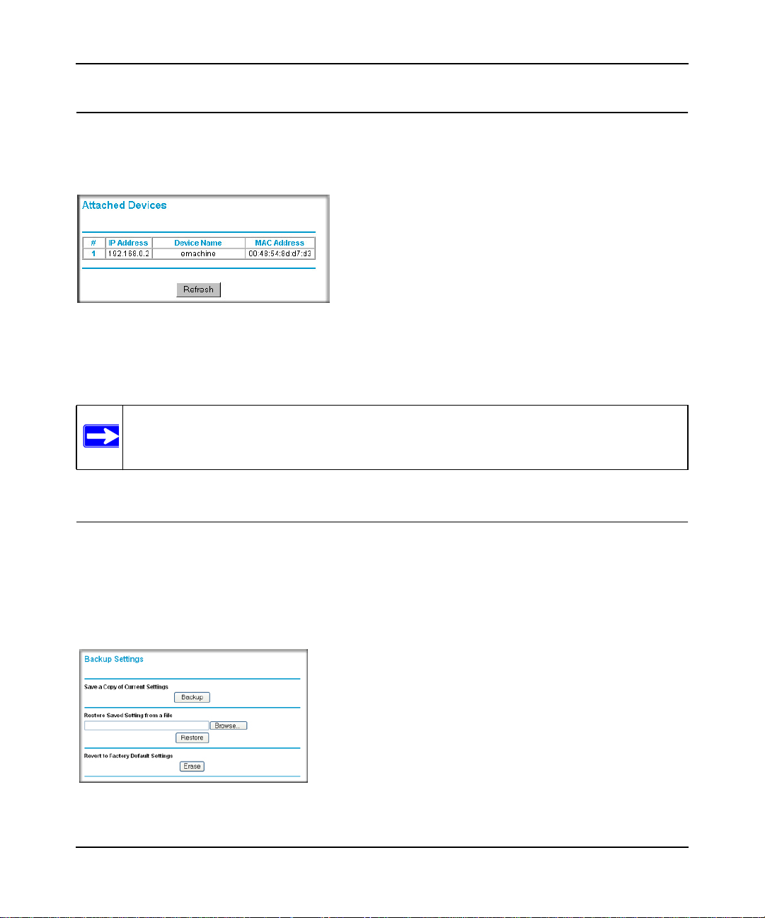
Viewing a List of Attached Devices
The Attached Devices screen contains a table of all IP devices that the router has discovered on the
local network. Select Attached Devices under Maintenance in the main menu to view the table.
Figure 6-4
For each device, the table shows the IP address, NetBIOS host name or device name (if available),
and the Ethernet MAC address. To force the router to look for attached devices, click Refresh.
Note: If the router is rebooted, the table data is lost until the router rediscovers the
devices.
Managing the Configuration File
The configuration settings of the WNR1000 v2h2 router are stored within the router in a
configuration file. You can back up this file to your computer, restore it, or reset it to the factory
default settings.
Select Backup Settings under Maintenance in the main menu to display the Backup Settings.
Figure 6-5
Using Network Monitoring Tools 6-7
v1.0, August 2010
Page 13
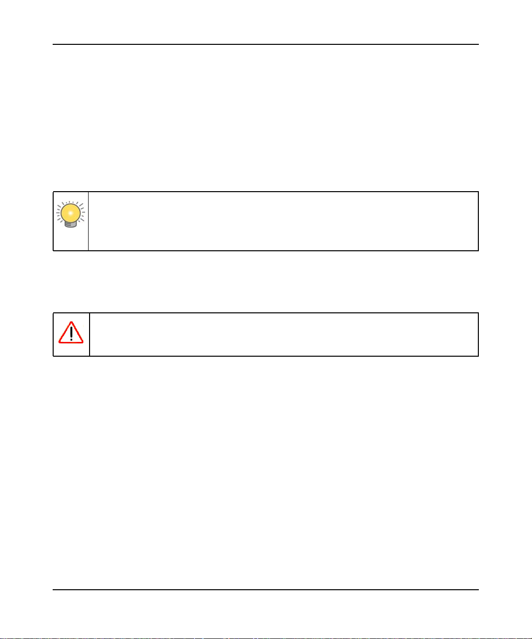
The following sections describe the three available options.
Backing Up and Restoring the Configuration
The Restore and Backup options in the Settings Backup screen let you save and retrieve a file
containing your router’s configuration settings.
To save your settings, click Backup. Your browser extracts the configuration file from the router
and prompts you for a location on your computer to store the file. You can give the file a
meaningful name at this time, such as comcast.cfg.
Tip: Before saving your configuration file, change the administrator password to the
default, password. Then change it again after you have saved the configuration file.
If you forget the password, you will need to reset the configuration to factory
defaults.
To restore your settings from a saved configuration file, enter the full path to the file on your
computer, or click Browse to browse to the file. When you have located it, click Restore to send
the file to the router. The router then reboots automatically.
Warning: Do not interrupt the reboot process.
Erasing the Configuration
Under some circumstances (for example, if you move the router to a different network or if you
have forgotten the password) you might want to erase the configuration and restore the factory
default settings. After an erase, the router’s username is admin, the password is password, the
LAN IP address is 192.168.1.1 (or www.routerlogin.net), and the router’s DHCP server is
enabled.
To erase the configuration, click the Erase button in the Settings Backup screen.
To restore the factory default configuration settings when you do not know the login password or
IP address, you must use the restore factory settings button on the rear panel of the router (see
“Restoring the Default Configuration and Password” on page 7-12).
Using Network Monitoring Tools 6-8
v1.0, August 2010
Page 14

Updating the Router Firmware
The firmware of the WNR1000 v2h2 router is stored in flash memory, and can be updated as
NETGEAR releases new firmware. You can update your firmware by logging into the router and
using one of these procedures:
• Enable the Check for Updated Firmware Upon Log-in check box. Each time you log in to
the router, it will automatically detect a new version of the firmware and then install it. This
check box is enabled in the router’s default state. See “Logging In To Your Wireless Router”
on page 1-2.
• Use the Check button in the Router Upgrade screen. Instead of having the router check for
new firmware every time you log in, you can use Router Upgrade, under Maintenance in the
main menu. See “Checking for New Firmware in the Router Upgrade Screen.”
• Check for and update your firmware manually. You can compare versions, obtain new
firmware from NETGEAR’s website, and then upload it. See “Updating Manually to New
Router Firmware” on page 6-10.
Note: Before updating the router software, NETGEAR recommends that you save your
configuration settings (see “Backing Up and Restoring the Configuration” on
page 6-8). A firmware update might cause the router settings to revert to the
factory defaults. If this happens, after completing the update, you can restore
your settings from the backup.
Checking for New Firmware in the Router Upgrade Screen
To check for new firmware and allow the router to automatically install it:
1. Select Router Upgrade under Maintenance in the main menu. The Router Upgrade screen
displays.
Figure 6-6
Using Network Monitoring Tools 6-9
v1.0, August 2010
Page 15

2. Check for new software versions by clicking the Check button.
• If a new version is found, information about it appears.
Figure 6-7
• If no new firmware version is available, a message displays and the router returns to the
Firmware Update screen.
Figure 6-8
3. To update your firmware, click Yes and follow the prompts.
Warning: When updating firmware to the WNR1000 v2h2 router, do not
interrupt the Web browser by closing the window, clicking a link,
or loading a new page. If the browser is interrupted, it could corrupt
the firmware.
When the upload is complete, your router automatically restarts. The update process typically
takes about 1 minute.
Updating Manually to New Router Firmware
To manually select, download, and install new software to your router:
Using Network Monitoring Tools 6-10
v1.0, August 2010
Page 16

1. Log in to your router, select Router Status under Maintenance on the main menu, and make
note of the firmware version of your router.
Figure 6-9
2. Go to the WNR1000 v2h2 support page on the NETGEAR website at
http://www.netgear.com/support.
3. Compare the version number of the most recent firmware offered to the firmware version of
your router. If the version on the NETGEAR website is more recent, download the file from
the WNR1000 v2h2 support page to your computer.
4. Log in to your router and select Router Upgrade under Maintenance on the main menu.
5. Click Browse, and locate the firmware image that you downloaded to your computer (the file
ends in .img or .chk).
6. Click Upload to send the firmware to the router.
Warning: When updating firmware to the WNR1000 v2h2 router, do not interrupt
the Web browser by closing the window, clicking a link, or loading a
new page. If the browser is interrupted, it could corrupt the firmware.
When the upload is complete, your router automatically restarts. The upgrade process
typically takes about 1 minute.
Using Network Monitoring Tools 6-11
v1.0, August 2010
Page 17

Enabling Remote Management Access
Using the Remote Management feature, you can allow a user on the Internet to configure, upgrade,
and check the status of your WNR1000 v2h2 router. Select Remote Management under Advanced in
the main menu. The Remote Management screen displays.
Figure 6-10
Note: Be sure to change the router’s default configuration password to a very secure
password. The ideal password should contain no dictionary words from any
language, and should be a mixture of letters (both uppercase and lowercase),
numbers, and symbols. Your password can be up to 30 characters.
To configure your router for remote management:
1. Select the Turn Remote Management On check box.
2. Under Allow Remote Access By, specify what external IP addresses will be allowed to access
the router’s remote management.
Note: For enhanced security, restrict access to as few external IP addresses
as practical.
Using Network Monitoring Tools 6-12
v1.0, August 2010
Page 18

• To allow access from any IP address on the Internet, select Everyone.
• To allow access from a range of IP addresses on the Internet, select IP Address Range.
Enter a beginning and ending IP address to define the allowed range.
• To allow access from a single IP address on the Internet, select Only This Computer.
Enter the IP address that will be allowed access.
3. Specify the port number for accessing the management interface.
Normal Web browser access uses the standard HTTP service port 80. For greater security,
enter a custom port number for the remote management Web interface. Choose a number
between 1024 and 65535, but do not use the number of any common service port. The default
is 8080, which is a common alternate for HTTP.
4. Click Apply to have your changes take effect.
Note: When accessing your router from the Internet, enter your router’s WAN IP address
into your browser’s address or location field, followed by a colon (:) and the
custom port number. For example, if your external address is 134.177.0.123 and
you use port number 8080, then enter http://134.177.0.123:8080 in your browser.
Using Network Monitoring Tools 6-13
v1.0, August 2010
Page 19

Traffic Meter
Traffic Metering allows you to monitor the volume of Internet traffic passing through your router’s
Internet port. With the Traffic Meter utility, you can set limits for traffic volume, set a monthly
limit, and get a live update of traffic usage.
To monitor traffic on your router, do the following:
1. On the Advanced menu, click Traffic Meter.
Figure 6-11
2. To enable the Traffic Meter, click the Enable Traffic Meter check box.
Using Network Monitoring Tools 6-14
v1.0, August 2010
Page 20

3. If you would like to record and restrict the volume of Internet traffic, click the Traffic volume
control by radio button. You can select one of the following options for controlling the traffic
volume:
• No Limit – No restriction is applied when the traffic limit is reached.
• Download only – The restriction is applied to incoming traffic only.
• Both Directions – The restriction is applied to both incoming and outgoing traffic.
4. You can limit the amount of data traffic allowed per month:
• By specifying how many Mbytes per month are allowed.
• By specifying how many hours of traffic are allowed.
5. Set the Traffic Counter to begin at a specific time and date.
6. Set up Traffic Control to issue a warning message before the month limit of Mbytes or Hours
is reached. You can select one of the following to occur when the limit is attained:
• The Internet LED flashes green or amber.
• The Internet connection is disconnected and disabled.
7. Set up Internet Traffic Statistics to monitor the data traffic.
8. Click the Traffic Status button if you want a live update on Internet traffic status on your
router.
9. Click Apply to save your settings.
Using Network Monitoring Tools 6-15
v1.0, August 2010
Page 21

Chapter 7
Troubleshooting
This chapter provides information about troubleshooting your N 150 Wireless Router WNR1000 v2h2
. After each problem description, instructions are provided to help you diagnose and
solve the problem. As a first step, please review the Quick Tips.
Tip: NETGEAR provides helpful articles, documentation, and the latest software
updates at http://www.netgear.com/support.
This chapter includes the following sections:
• “Quick Tips”
• “Troubleshooting Basic Functions” on page 7-2
• “Login Problems” on page 7-5
• “Checking the Internet Service Connection” on page 7-6
• “Troubleshooting Your Network Using the Ping Utility” on page 7-8
• “Problems with Date and Time” on page 7-10
• “Problems with Wireless Adapter Connections” on page 7-11
• “Restoring the Default Configuration and Password” on page 7-12
Quick Tips
This section describes tips for troubleshooting some common problems:
Be sure to restart your network in this sequence.
1. Turn off and unplug the modem.
2. Turn off the wireless router and computers.
3. Plug in the modem and turn it on. Wait 2 minutes.
v1.0, August 2010
7-1
Page 22

4. Turn on the wireless router and wait 1 minute.
5. Turn on the computers.
Make sure that the Ethernet cables are securely plugged in.
• The Internet status light on the wireless router is on if the Ethernet cable connecting the
wireless router and the modem is plugged in securely and the modem and wireless router are
turned on.
• For each powered-on computer connected to the wireless router by an Ethernet cable, the
corresponding numbered router LAN port light is on.
Make sure that the wireless settings in the computer and router match exactly.
• For a wirelessly connected computer, the wireless network name (SSID) and WEP or WPA
security settings of the router and wireless computer must match exactly.
• If you have enabled the wireless router to restrict wireless access by MAC address, you must
add the wireless computer’s MAC address to the router’s wireless card access list.
Make sure that the network settings of the computer are correct.
• LAN connected computers must be configured to obtain an IP address automatically using
DHCP. For more information, see the links in Appendix B, “Related Documents.
• Some cable modem services require you to use the MAC address of the computer registered
on the account. If so, in the Router MAC Address section of the Basic Settings menu, select
Use this Computer’s MAC Address. Click Apply to save your settings. Restart the network
in the correct sequence.
Check the Test light to verify correct router operation.
If the Test light does not turn off within 2 minutes after you turn the router on, reset the router
according to the instructions in “Restoring the Default Configuration and Password” on page 7-12.
Troubleshooting Basic Functions
After you turn on power to the router, the following sequence of events should occur:
1. When power is first applied, verify that the Power light is on.
2. Verify that the power light turns amber within a few seconds, indicating that the self-test
procedure is running.
Troubleshooting 7-2
v1.0, August 2010
Page 23

3. After approximately 20 seconds, verify that:
a. The color of the power light changes to green.
b. The LAN port lights are lit for any local ports that are connected.
If a port’s light is lit, a link has been established to the connected device. If a LAN port is
connected to a 100 Mbps device, verify that the port’s light is green. If the port is 10
Mbps, the light will be amber.
c. The Internet port is connected and its light is lit.
4. If you have enabled WPS security, verify that the push-button stops blinking and changes to
green (otherwise the push-button light should be off).
If the correct behavior does not occur, see the appropriate following section.
The Power light is not on.
If the Power and other lights are off when your router is turned on:
• Make sure that the power cord is properly connected to your router and that the power adapter
is properly connected to a functioning power outlet.
• Check that you are using the power adapter supplied by NETGEAR for this product.
If the error persists, you have a hardware problem and should contact Technical Support.
The Power light blinks green slowly and continuously.
The router firmware is corrupted.
To restore your firmware:
1. Make sure your PC is connected to your router and the router is powered on.
2. Insert the Resource CD that came with your router into your PC.
a. The CD will automatically start and detect the language you are using on your PC. Select
a different language option, if you prefer.
b. If the CD does not automatically start, browse the CD and double-click on .
3. Click Supporting Software, then Netgear Firmware Recovery Utility, and follow the
prompts for the recovery process.
4. After firmware recovery is completed, follow the prompts to restore your configuration
settings.
Troubleshooting 7-3
v1.0, August 2010
Page 24

The Power light stays amber.
When the router is turned on, the Power light turns amber for about 20 seconds and then turns
green. If the light does not turn green, the router has a problem.
If the Power light is still amber 1 minute after turning on power to the router:
1. Turn the power off and back on to see if the router recovers.
2. Clear the router’s configuration to factory defaults. This will set the router’s IP address to
www.routerlogin.net. This procedure is explained in “Restoring the Default Configuration and
Password” on page 7-12.
If the error persists, you might have a hardware problem and should contact Technical Support.
The Internet light stays amber.
When the router is turned on, the Internet light turns amber for about 20 seconds and then turns
green. If the light does not turn green, the router has a problem.
If the Internet light is still amber 1 minute after turning on power to the router:
1. The Internet is not accessible. Confirm that you have the correct internet setting.
2. Clear the router’s configuration to factory defaults. This will set the router’s IP address to
www.routerlogin.net. This procedure is explained in “Restoring the Default Configuration and
Password” on page 7-12.
3. Turn the power off and back on to see if the router recovers.
The Internet or LAN port lights are not on.
If either the LAN or Internet lights do not light when the Ethernet connection is made, check the
following:
1. Make sure that the Ethernet cable connections are secure at the router and at the computer.
2. Make sure that power is turned on to the connected computer.
3. Be sure you are using Ethernet cables like the cable that was supplied with the wireless router.
See the NETGEAR Wireless Router Setup Manual for instructions.
The Push 'N' Connect (WPS) push-button blinks amber.
If after using the WPS function the push-button blinks amber, check the following:
1. Make sure that you are using the push-button and not the router’s built-in registrar.
Troubleshooting 7-4
v1.0, August 2010
Page 25

2. Check that PIN verification has succeeded for the WPS-enabled device you are connecting to
the router.
3. Make sure you have not pushed the push-button after disabling the WPS function (you logged
into the router and disabled this previously).
4. Check that the router is not in the temporary AP setup locked state (if you are using the
wireless repeater function).
For more information on WPS, see “Using Push 'N' Connect (Wi-Fi Protected Setup)” on
page 2-13.
Login Problems
If you are unable to log in to the wireless router, check the following:
• If you are using an Ethernet-connected computer, check the Ethernet connection between the
computer and the router as described in the NETGEAR Wireless Router Setup Manual.
• Make sure you are using the correct login information. The factory default login name is
admin and the password is password. Make sure that the Caps Lock is off when entering this
information.
• Make sure your computer’s IP address is on the same subnet as the router. If your are using the
recommended addressing scheme, your computer’s address should be in the range of
192.168.1.2 to 192.168.1.254. Refer to your computer’s documentation or see “Preparing
Your Network” in Appendix B for help with configuring your computer.
Note: If your computer cannot reach a DHCP server, some operating systems will
assign an IP address in the range 169.254.x.x. If your IP address is in this
range, verify that you have a good connection from the computer to the router,
then restart (reboot) your computer.
• If your router’s IP address has been changed and you don’t know the current IP address, reset
the router’s configuration to the factory defaults. This procedure will reset the router’s IP
address to 192.168.1.1 (see “Default Configuration Settings” in Appendix A).
• Make sure your browser has Java, JavaScript, or ActiveX enabled. If you are using Internet
Explorer, click Refresh to be sure the Java applet is loaded. Try closing the browser and
reopening it again.
Troubleshooting 7-5
v1.0, August 2010
Page 26

• If you are attempting to set up your NETGEAR router as an additional router behind an
existing router in your network, consider replacing the existing router instead. NETGEAR
does not support such a configuration.
• If you are attempting to set up your NETGEAR router as a replacement for an ADSL gateway
in your network, the router cannot perform many gateway services, for example, converting
ADSL or Cable data into Ethernet networking information. NETGEAR does not support such
a configuration.
Checking the Internet Service Connection
If you can access your router, but your router is unable to access the Internet, review the topics in
this section:
• “Obtaining an Internet IP Address”
• “Troubleshooting PPPoE”
• “Troubleshooting Internet Browsing”
Obtaining an Internet IP Address
If your wireless router is unable to access the Internet, and your Internet light is amber, check the
wireless router to see if it is able to get an Internet IP address from your service provider. Unless
you have a static IP address, your wireless router automatically requests an IP address from your
service provider.
To check your wireless router’s Internet IP address:
1. Log in to the wireless router.
2. Select Router Status, under Maintenance in the main menu, to check that an IP address is
shown for the Internet Port. If 0.0.0.0 is shown, your wireless router has not obtained an IP
address from your service provider.
If your router is unable to obtain an IP address from the your service provider, the problem might
be one of the following:
Troubleshooting 7-6
v1.0, August 2010
Page 27

• You might need to force your cable or DSL modem to recognize your new router by restarting
your network, in the sequence described in the NETGEAR Wireless Router Setup Manual.
• Your service provider might require a login. Ask your service provider whether they require a
PPP over Ethernet (PPPoE) login (see “Troubleshooting PPPoE” on page 7-7).
• You might have incorrectly set the service name, user name or password. Review your
router’s Basic Settings screen.
• Your service provider might check for your computer's host name. Assign the computer Host
Name of your ISP account to the wireless router on the Basic Settings screen.
• Your service provider might only allow one Ethernet MAC address to connect to the Internet,
and check for your computer’s MAC address. If this is the case:
– Inform your service provider that you have bought a new network device, and ask them to
use the wireless router’s MAC address, or
– Configure your router to spoof your computer’s MAC address. On the Basic Settings
screen in the Router MAC Address section, select “Use this Computer’s MAC Address”
and click Apply. Then restart your network in the correct sequence (see the NETGEAR
Wireless Router Setup Manual for instructions).
Troubleshooting PPPoE
If you are using PPPoE, try troubleshooting your Internet connection.
To troubleshoot a PPPoE connection:
1. Log in to the wireless router.
2. Select Router Status under Maintenance on the main menu.
3. Click Connection Status. If all of the steps indicate “OK,” then your PPPoE connection is up
and working.
If any of the steps indicate “Failed,” you can attempt to reconnect by clicking Connect. The
wireless router will continue to attempt to connect indefinitely.
If you cannot connect after several minutes, you might be using an incorrect service name,
user name, or password. There also might be a provisioning problem with your ISP.
Note: Unless you connect manually, the wireless router will not authenticate using
PPPoE until data is transmitted to the network.
Troubleshooting 7-7
v1.0, August 2010
Page 28

Troubleshooting Internet Browsing
If your wireless router can obtain an IP address but your computer is unable to load any web pages
from the Internet, check the following:
• Your computer might not recognize any DNS server addresses. A DNS server is a host on
the Internet that translates Internet names (such as www addresses) to numeric IP addresses.
Typically, your ISP will provide the addresses of one or two DNS servers for your use. If you
entered a DNS address during the wireless router’s configuration, restart your computer.
Alternatively, you can configure your computer manually with a DNS address, as explained in
the documentation for your computer.
• Your computer might not have the wireless router configured as its default gateway.
Reboot the computer and verify that the wireless router address (www.routerlogin.net) is listed
by your computer as the default gateway address.
• You might be running login software that is no longer needed. If your ISP provided a
program to log you in to the Internet (such as WinPoET), you no longer need to run that
software after installing your router. You might need to go to Internet Explorer and select
Tools > Internet Options, click the Connections tab, and select Never dial a connection.
If the wireless router does not save changes you have made in the browser interface, check the
following:
• When entering configuration settings, be sure to click Apply before moving to another screen
or tab, or your changes could be lost.
• Click Refresh or Reload in the Web browser. The changes might have occurred, but the Web
browser might be caching the old configuration.
Troubleshooting Your Network Using the Ping Utility
Most network devices and routers contain a ping utility that sends an echo request packet to the
designated device. The device then responds with an echo reply. Troubleshooting a network is
made very easy by using the ping utility in your computer or workstation. This section includes:
• “Testing the LAN Path to Your Router”
• “Testing the Path from Your Computer to a Remote Device”
Troubleshooting 7-8
v1.0, August 2010
Page 29

Testing the LAN Path to Your Router
You can ping the router from your computer to verify that the LAN path to your router is set up
correctly.
To ping the router from a running Windows PC:
1. From the Windows toolbar, click Start, and then select Run.
2. In the field provided, type ping followed by the IP address of the router, as in this example:
ping www.routerlogin.net
3. Click OK.
You should see a message like this one:
Pinging <IP address > with 32 bytes of data
If the path is working, you see this message:
Reply from < IP address >: bytes=32 time=NN ms TTL=xxx
If the path is not working, you see this message:
Request timed out
If the path is not functioning correctly, you could have one of the following problems:
• Wrong physical connections
– For a wired connection, make sure that the numbered LAN port light is on for the port
to which you are connected. If the light is off, follow the instructions in
“Troubleshooting Basic Functions” on page 7-2.
– Check that the appropriate LEDs are on for your network devices. If your router and
computer are connected to a separate Ethernet switch, make sure that the link lights
are on for the switch ports that are connected to your computer and router.
• Wrong network configuration
– Verify that the Ethernet card driver software and TCP/IP software are both installed
and configured on your computer.
– Verify that the IP address for your router and your computer are correct and that the
addresses are on the same subnet.
Troubleshooting 7-9
v1.0, August 2010
Page 30

Testing the Path from Your Computer to a Remote Device
After verifying that the LAN path works correctly, test the path from your computer to a remote
device.
1. From the Windows toolbar, click the Start button, and then select Run.
2. In the Windows Run window, type:
ping -n 10 <IP address>
where <IP address> is the IP address of a remote device such as your ISP’s DNS server.
If the path is functioning correctly, replies like those shown in the previous section are displayed.
If you do not receive replies:
• Check that your computer has the IP address of your router listed as the default gateway. If the
IP configuration of your computer is assigned by DHCP, this information is not be visible in
your computer’s Network Control Panel. Verify that the IP address of the router is listed as the
default gateway as described in the online document you can access from “Preparing Your
Network” in Appendix B.
• Check to see that the network address of your computer (the portion of the IP address specified
by the subnet mask) is different from the network address of the remote device.
• Check that your cable or DSL modem is connected and functioning.
• If your ISP assigned a host name to your computer, enter that host name as the account name
in the Basic Settings screen.
• Your ISP could be rejecting the Ethernet MAC addresses of all but one of your computers.
Many broadband ISPs restrict access by allowing traffic only from the MAC address of your
broadband modem, but some ISPs additionally restrict access to the MAC address of a single
computer connected to that modem. If this is the case, you must configure your router to
“clone” or “spoof” the MAC address from the authorized computer. For more information, see
“Using the Setup Manual” on page 1-1.
Problems with Date and Time
Select E-mail under Content Filtering in the main menu to display a screen that shows the current
date and time of day. The WNR1000 v2h2 router uses the Network Time Protocol (NTP) to obtain the
current time from one of several network time servers on the Internet. Each entry in the log is
stamped with the date and time of day. Problems with the date and time function can include the
following:
Troubleshooting 7-10
v1.0, August 2010
Page 31

• Date shown is January 1, 2000.
Cause: The router has not yet successfully reached a network time server. Check that your
Internet access settings are correct. If you have just completed configuring the router, wait at
least 5 minutes, and check the date and time again.
• Time is off by one hour.
Cause: The router does not adjust for daylight savings time. In the E-mail screen, select the
Automatically Adjust for Daylight Savings Time check box.
Problems with Wireless Adapter Connections
If your wireless adapter is unable to connect, check its connection settings.
To check the adapter’s connection settings:
1. open the adapter setup utility to check connections:
• NETGEAR Smart Wizard utility. If you installed a NETGEAR wireless adapter in your
computer, a Smart Wizard utility program is installed that can provide helpful information
about your wireless network. You can find this program in your Windows Program menu
or as an icon in your system tray. Other wireless card manufacturers might include a
similar program.
• Windows basic setup utility. If you have no specific wireless card setup program
installed, you can use the basic setup utility in Windows:
– Open the Windows Control Panel, and double-click Network Connections.
– In the LAN section, double-click Wireless Network Connection.
2. Use the adapter’s setup program to scan for available wireless networks, looking for the
network name (SSID) of NETGEAR, or your custom SSID if you have changed it.
3. If your wireless network appears and has good signal strength, configure and test with the
simplest wireless connection possible.
If your wireless network does not appear, check these conditions:
• Is your router’s wireless radio enabled? See “Viewing Advanced Wireless Settings” on
page 2-11.
• Is your router’s SSID broadcast enabled? See “Viewing Advanced Wireless Settings” on
page 2-11.
Troubleshooting 7-11
v1.0, August 2010
Page 32

• Is your router set to a wireless standard that is not supported by your wireless adapter? Check
the Mode setting as described in “Viewing and Configuring Basic Internet Settings” on
page 1-6.
If your wireless network appears, but the signal strength is weak, check these conditions:
• Is your router too far from your adapter, or too close? Place the computer that has the adapter
near the router, but at least 6 feet away, and see whether the signal strength improves.
• Is your wireless signal obstructed by objects between the router and your adapter? See
“Optimizing Wireless Performance” on page 5-14.
Restoring the Default Configuration and Password
This section explains how to restore the factory default configuration settings that reset the
router’s user name to admin, the password to password, and the IP address to 192.168.1.1.
Warning: These procedures erase all current configuration settings.
You can erase the current configuration and restore factory defaults in two ways:
• Use the Erase function of the router. To use the Erase function, see “Erasing the
Configuration” on page 6-8.
• Use the restore factory settings button on the rear panel of the router. Use this method for cases
when the administration password or IP address is not known.
To use the restore settings button:
1. Locate the restore factory settings button on the rear panel of the router.
2. Use a sharp object such as a pen or a paper clip to press and hold the restore factory settings
button for about 5 seconds, until the Power light begins to blink.
3. Release the restore factory settings button, and wait for the router to restart, and for the Power
light to stop blinking and become solid green.
The factory default settings will be restored so that you can access the router from your Web
browser using the factory defaults.
Troubleshooting 7-12
v1.0, August 2010
Page 33

If the wireless router fails to restart, or the Power light continues to blink or turns solid amber, the
unit might be defective. If the error persists, you might have a hardware problem and should
contact Technical Support at http://www.netgear.com/support.
Troubleshooting 7-13
v1.0, August 2010
Page 34

Appendix A
Technical Specifications
Default Configuration Settings
This appendix provides factory default settings and technical specifications for the N 150 Wireless
Router WNR1000 v2h2 .
Table A-1. WNR1000 v2h2 Router Default Configuration Settings
Feature Default Setting
Router Login
Router Login URL http://www.routerlogin.net or
http://www.routerlogin.com
Login Name (case-sensitive) printed on
product label
Login Password (case-sensitive) printed on
product label
Internet Connection
WAN MAC Address Default hardware address (on label)
MTU Size 1500
Local Network
Router LAN IP address printed on product label
(also known as Gateway IP address)
Router Subnet 255.255.255.0
DHCP Server Enabled
DHCP range 192.168.1.2 to 192.168.1.254
Time Zone GMT
Time Zone Adjusted for Daylight Saving Time Disabled
Allow a Registrar to configure this router Enabled
admin
password
192.168.1.1
Technical Specifications A-1
v1.0, August 2010
Page 35

Table A-1. WNR1000v2 Router Default Configuration Settings (continued)
Wireless
Wireless Communication
SSID Name
Security Disabled
Wireless Access List (MAC Filtering)
Broadcast SSID Enabled
Transmission Speed Auto
Country/Region United States (North America only; otherwise
RF Channel
Operating Mode Up to 150 Mbps
Data Rate Best
Output Power Full
Firewall
Inbound (communications coming in from the Internet) Disabled (bars all unsolicited requests except
Outbound (communications going out to the Internet) Enabled (all)
*. Maximum Wireless signal rate derived from IEEE Standard 802.11 specifications. Actual throughput will vary. Network
conditions and environmental factors, including volume of network traffic, building materials and construction, and network
overhead lower actual data throughput rate.
Enabled
NETGEAR
All wireless stations allowed
*
varies by country and region)
Auto
for traffic on port 80, the http port)
Technical Specifications A-2
v1.0, August 2010
Page 36

General Specifications
Table A-2. WNR1000v2 Router General Specifications
Feature General
Network Protocol and Standards Compatibility
Data and Routing Protocols TCP/IP, RIP-1, RIP-2, DHCP, PPPoE, PPTP, Bigpond, Dynamic
DNS, and UPnP
Power Adapter
North America 120V, 60 Hz, input
UK, Australia 240V, 50 Hz, input
Europe 230V, 50 Hz, input
Japan 100V, 50/60 Hz, input
All regions (output) 12V DC @ 1.0A, output
Physical
Dimensions 28 x 175 x 119 mm (1.1 x 6.89 x 4.68 in.)
Weight 0.26 kg (0.57 lb)
Environmental
Operating temperature 0 to 40 C (32º to 104º F)
Operating humidity 90% maximum relative humidity, noncondensing
Electromagnetic Emissions
Designed to conform to the
following standards
Interface Specifications
LAN 10BASE-T or 100BASE-Tx, RJ-45
WAN 10BASE-T or 100BASE-Tx, RJ-45
FCC Part 15 Class B
EN 55022/24 (CISPR 22/24) Class B
EN 60950 (CE LVD) Class B
MIC
Technical Specifications A-3
v1.0, August 2010
Page 37

Appendix B
Related Documents
This appendix provides links to reference documents you can use to gain a more complete
understanding of the technologies used in your NETGEAR product.
Table B-1. Reference Documents
Document Link
TCP/IP Networking Basics
Wireless Networking Basics
Preparing Your Network
Virtual Private Networking
Basics
Glossary
http://documentation.netgear.com/reference/enu/tcpip/index.htm
http://documentation.netgear.com/reference/enu/wireless/index.htm
http://documentation.netgear.com/reference/enu/wsdhcp/index.htm
http://documentation.netgear.com/reference/enu/vpn/index.htm
http://documentation.netgear.com/reference/enu/glossary/index.htm
In addition, you can find initial setup instructions for your wireless router in the NETGEAR
Wireless Router Setup Manual.
Related Documents B-1
v1.0, August 2010
Page 38

Index
A
access
blocking 3-1
remote 6-12
restricting by MAC address 2-18
to a remote computer 5-2
to the router 1-2
viewing logs 3-6
access control
turning off 1-13
turning on 2-20
account name 1-7
adding
custom service 5-7
reserved IP addresses 4-4
static routes 4-9
wireless clients 2-13, 2-17, 6-4
See also configuring
administrator password, changing 2-20
advanced wireless settings 2-11
advertisement period 5-13
AES (Advanced Encryption Standard) encryption 2-10
attached devices 6-7
authentication, required by mail server 3-8
automatic logout 1-4
B
backing up configuration file 6-8
backing up, transfer time 5-18
basic settings 2-6
Big Pond 1-10
blocking
access 3-1
inbound traffic 5-1
bold text xi
broadband Internet 5-16
broadcast status 6-4
C
cables, checking 7-2
channel, frequency 2-7
channel, wireless port 6-4
clients, adding 2-13, 2-17, 6-4
communication mode 2-7, 6-4
compatibility, protocol and standards A-3
configuration file
backing up 6-8
erasing 6-8
managing 6-7
configuring
advanced security 2-11
basic security 2-6
DMZ server 4-7
Dynamic DNS 4-5
LAN IP settings 4-1
NAT 4-8
port forwarding 5-6
port triggering 5-9
WPA security 2-10
WPS 2-16
See also adding
connection mode 1-10
connection status settings 6-5
connection types 5-16
content filtering 3-1
CTS/RTS Threshold 2-12
custom service (port forwarding) 5-7
customer support ii
v1.0, August 2010
Index-1
Page 39

D
data packets, fragmented 5-15
date and time, troubleshooting 7-10
daylight savings time 3-8, 7-11
default DMZ server 4-7
default factory settings
listed A-1
restoring 7-12
default gateway 6-5
default LAN IP configuration 4-2
deleting configuration 6-8
device name 4-2
DHCP server 4-3, 6-5
DHCP setting 6-3
disabling
firewall 4-6
router PIN 2-17
DMZ server 4-7
DNS servers 5-2
Documentation Web page 1-4
documents, reference B-1
domain name 1-7
Domain Name Server (DNS) addresses
current 6-3
entering 1-8, 1-11
Dynamic DNS 4-5
dynamic IP addresses 1-7
DynDNS.org 4-5
E
electromagnetic emissions A-3
e-mailing logs 3-7
encryption 2-1
encryption keys 2-9
environmental specifications A-3
erasing configuration 6-8
Ethernet MAC address 6-7
F
factory default settings
listed A-1
restoring 7-12
filtering content 3-1
firewalls
default settings A-2
disabling 4-6
overview 2-22
firmware
restoring 7-3
updating 1-3, 6-3, 6-9
fixed font text xi
fixed IP addresses 1-8
Fragmentation Threshold 2-12
fragmented data packets 5-15
frequency, channel 2-7
G
generating encryption keys 2-9
Gigabit Ethernet 5-17
H
hardware version 6-3
host name 1-7, 6-7
HTML version, printing xii
I
idle time-out 1-11
inbound traffic, allowing or blocking 5-1
interface specifications A-3
interference, reducing 5-14
Internet connection
default settings A-1
Internet port, status 6-3
Internet Relay Chat (IRC) 5-3
Internet services, blocking access 3-3
interval, poll 6-6
v1.0, August 2010
Index-2
Page 40

IP addresses
blocking access by 3-5
current 6-3
dynamic or static 1-7
LAN 4-2
registering domain name 4-5
reserved 4-4
IP subnet mask 4-2, 6-3
ISP settings, basic 1-6
italic text xi
K
keys, encryption 2-9
keywords, blocking by 3-1
knowledge base 1-4
L
LAN IP setup 4-1
LAN path, troubleshooting 7-9
LAN port settings 6-3
language, screen display 1-4
lease, DHCP 6-5
Legacy mode 2-7
local network, default settings A-1
local servers, port forwarding to 5-6
logging in 1-2
login required 1-9
login settings A-1
logout, automatic 1-4
logs
sending 3-7
time-stamping entries 3-8
viewing 3-6
M
MAC addresses
attached devices 6-7
current 6-3
entering 1-8
restricting access by 2-18
spoofing 7-7
mail server, outgoing 3-7
managing router remotely 6-12
metric value 4-10
mixed mode encryption 2-3, 2-10
mode, communication 2-7, 6-4
MTU size 4-8, 5-15
N
NAT (Network Address Translation) 4-7, 4-8, 5-2
NetBIOS host name 6-7
Network Time Protocol (NTP) 3-8, 7-10
O
obstructions, connecting through 5-17
Open System authentication 2-8
optimizing performance 5-14
outgoing mail server 3-7
P
passphrases 2-8, 2-9, 2-10
password
changing 2-20
restoring 7-12
path, testing 7-10
performance, optimizing 5-14
physical push button (WPS) 2-13
physical specifications A-3
PIN 2-15, 2-17
ping 4-7, 7-8
placement, router 5-14
poll interval 6-6
port filtering 3-3
port forwarding
configuring 5-6
example 5-5
port numbers 3-3
v1.0, August 2010
Index-3
Page 41

port status 6-6
port triggering
configuring 5-9
example 5-3
portmap table 5-13
power adapter specifications A-3
Power light, troubleshooting and 7-2
Powerline HD products 5-17
PPPoE (PPP over Ethernet) 1-10
PPTP (Point to Point Tunneling Protocol) 1-10
Preamble mode 2-12
primary DNS server 1-8, 1-11
printing manual xii
protocols, compatibility A-3
Push ’N’ Connect 2-13, 6-4, 7-4
push button configuration (WPS) 2-13
R
radio, wireless 1-13, 2-12, 6-4
range, router 5-14
reducing interference 5-14
reference documents B-1
region of operation 2-7
registering product ii
releasing connection status 6-5
remote devices, testing path 7-10
remote management 6-12
renewing connection status 6-5
requirements, speed 5-17
reserved IP adresses 4-4
Resource CD 1-1
restarting network 7-1
restoring
configuration 6-8
default factory settings 7-12
restoring firmware 7-3
restricting access by MAC address 2-18
revision history xiii
RIP (Router Information Protocol) direction 4-2
route name 4-10
router PIN 2-15, 2-17
router status, viewing 6-2
S
scheduling blocking 3-5
screen display language 1-4
selecting 1-4
secondary DNS server 1-8, 1-11
security
options, compared 2-2
setting up 2-1
security PIN 2-15, 2-17
service name 1-10
service numbers 3-4
services, blocking 3-3
setting time 3-8
settings, default. See default factory settings
setup information, gathering 2-5
Setup Manual 1-1
Setup Wizard 1-6
Shared Key authentication 2-5, 2-8
SMTP server 3-7
software push button configuration (WPS) 2-14
specifications
technical A-1
speed requirements 5-17
SPI (Stateful Packet Inspection) firewall 4-6
spoofing MAC addresses 1-8, 7-7
SSID 1-12, 2-7, 6-4
SSID broadcast 1-13, 2-12
standards, compatibility A-3
static IP addresses 1-8
static routes 4-8
statistics, usage 6-6
status, viewing
streaming video and audio 5-17
6-2
v1.0, August 2010
Index-4
Page 42

subnet mask 4-2, 6-3
system up time 6-6
T
TCP/IP network, troubleshooting 7-8
technical specifications A-1
Telstra Bigpond 1-10
time of day, troubleshooting 7-10
time to live, advertisement 5-13
time, setting 3-8
time-out
idle 1-11
port triggering 5-11
TKIP (Temporal Key Integrity Protocol) encryption 2-10
trademarks ii
traffic metering 6-14
transfer time (backing up) 5-18
troubleshooting 7-1
trusted user 3-2
typographical conventions xi
W
WAN setup 4-6
WEP encryption 2-3, 2-8
Wi-Fi Protected Setup (WPS) 2-13, 6-4, 7-4
wildcards, DNS and 4-6
Wireless Card Access List 2-18, 2-19
wireless client PIN 2-15
wireless clients, adding 2-13, 2-17, 6-4
wireless connection type 5-17
wireless network name 1-12, 2-7, 6-4
wireless port settings 6-4
wireless radio 1-13, 2-12, 6-4
wireless security, setting up 2-1
wireless settings
advanced 2-11
basic 2-6
default, listed A-2
gathering information 2-5
WPA2-PSK encryption 2-3, 2-10
WPA-PSK + WPA2-PSK encryption 2-3, 2-10
WPA-PSK encryption 2-3, 2-10
U
Universal Plug and Play (UPnP) 5-12
up time, system 6-6
updating firmware 1-3, 6-3, 6-9
URLs
typography for xi
usage statistics 6-6
V
version
firmware 6-3, 6-9
RIP (Router Information Protocol) 4-2
viewing
advanced wireless settings 2-11
attached devices 6-7
basic security settings 2-6
logs 3-6
status 6-2
Index-5
v1.0, August 2010
 Loading...