

Page 1

ProSafe Wireless-N VPN Firewall
FCC Radiation Exposure Statement
This equipment complies with FCC RF radiation exposure limits set forth for an uncontrolled environment. This equipment should be installed
and operated with a minimum distance of 20 centimeters between the radiator and your body.
This device complies with Part 15 of the FCC Rules. Operation is subject to the following two conditions:
1) This device may not cause harmful interference, and
2) This device must accept any interference received, including interference that may cause undesired operation.
This transmitter must not be co-located or operating in conjunction with any other antenna or transmitter.
The antennas used for this transmitter must be installed to provide a spectrum distance of at least 20cm from all persons and must not be co-
located or operating in conjunction with any other antenna or transmitter.
SRXN3205 Reference Manual
© 2008 by NETGEAR, Inc. All rights reserved.
Trademarks
NETGEAR and the NETGEAR logo are registered trademarks and ProSafe is a trademark of NETGEAR, Inc.
Microsoft, Windows, and Windows NT are registered trademarks of Microsoft Corporation. Other brand and product
names are registered trademarks or trademarks of their respective holders.
Statement of Conditions
In the interest of improving internal design, operational function, and/or reliability, NETGEAR reserves the right to
make changes to the products described in this document without notice.
NETGEAR does not assume any liability that may occur due to the use or application of the product(s) or circuit
layout(s) described herein.
Federal Communications Commission (FCC) Compliance Notice: Radio Frequency
Notice
This equipment has been tested and found to comply with the limits for a Class B digital device, pursuant to part 15 of
the FCC Rules. These limits are designed to provide reasonable protection against harmful interference in a residential
installation. This equipment generates, uses, and can radiate radio frequency energy and, if not installed and used in
accordance with the instructions, may cause harmful interference to radio communications. However, there is no
guarantee that interference will not occur in a particular installation. If this equipment does cause harmful interference
to radio or television reception, which can be determined by turning the equipment off and on, the user is encouraged to
try to correct the interference by one or more of the following measures:
. • Reorient or relocate the receiving antenna.
. • Increase the separation between the equipment and receiver.
. • Connect the equipment into an outlet on a circuit different from that to which the receiver is connected.
. • Consult the dealer or an experienced radio/TV technician for help.
1.0, July 2008
Page 2

EU Regulatory Compliance Statement
The ProSafe Wireless-N VPN Firewall is compliant with the following EU Council Directives: 89/336/EEC and LVD
73/23/EEC. Compliance is verified by testing to the following standards: EN55022 Class B, EN55024 and EN60950-1.
Bestätigung des Herstellers/Importeurs
Es wird hiermit bestätigt, daß das ProSafe Wireless-N VPN Firewall gemäß der im BMPT- AmtsblVfg 243/1991 und
Vfg 46/1992 aufgeführten Bestimmungen entstört ist. Das vorschriftsmäßige Betreiben einiger Geräte (z.B. T e stsender)
kann jedoch gewissen Beschränkungen unterliegen. Lesen Sie dazu bitte die Anmerkungen in der Betriebsanleitung.
Das Bundesamt für Zulassungen in der Telekommunikation wurde davon unterrichtet, daß dieses Gerät auf den Markt
gebracht wurde und es ist berechtigt, die Serie auf die Erfüllung der Vorschriften hin zu überprüfen.
Certificate of the Manufacturer/Importer
It is hereby certified that the ProSafe Wireless-N VPN Firewall has been suppressed in accordance with the conditions
set out in the BMPT-AmtsblVfg 243/1991 and Vfg 46/1992. The operation of some equipment (for example, test
transmitters) in accordance with the regulations may, however, be subject to certain restrictions. Please refer to the notes
in the operating instructions.
Federal Office for Telecommunications Approvals has been notified of the placing of this equipment on the market
and has been granted the right to test the series for compliance with the regulations.
Voluntary Control Council for Interference (VCCI) Statement
This equipment is in the second category (information equipment to be used in a residential area or an adjacent area
thereto) and conforms to the standards set by the Voluntary Control Council for Interference by Data Processing
Equipment and Electronic Office Machines aimed at preventing radio interference in such residential areas.
When used near a radio or TV receiver , it may become the cause of radio interference.
Read instructions for correct handling.
Additional Copyrights
AES Copyright (c) 2001, Dr Brian Gladman <brg@gladman.uk.net>, Worcester, UK.
All rights reserved.
TERMS
Redistribution and use in source and binary forms, with or without modification, are permitted
subject to the following conditions:
1. Redistributions of source code must retain the above copyright notice, this list of
conditions and the following disclaimer.
2. Redistributions in binary form must reproduce the above copyright notice, this list of
conditions and the following disclaimer in the documentation and/or other materials
provided with the distribution.
3. The copyright holder's name must not be used to endorse or promote any products
derived from this software without his specific prior written permission.
This software is provided 'as is' with no express or implied warranties of correctness or fitness
for purpose.
ii
1.0, July 2008
Page 3

Open SSL Copyright (c) 1998-2000 The OpenSSL Project. All rights reserved.
Redistribution and use in source and binary forms, with or without modification, are permitted
provided that the following conditions * are met:
1. Redistributions of source code must retain the above copyright notice, this list of conditions
and the following disclaimer.
2. Redistributions in binary form must reproduce the above copyright notice, this list of
conditions and the following disclaimer in the documentation and/or other materials
provided with the distribution.
3. All advertising materials mentioning features or use of this software must display the
following acknowledgment: “This product includes software developed by the OpenSSL
Project for use in the OpenSSL Toolkit. (http://www.openssl.org/)”
4. The names "OpenSSL Toolkit" and "OpenSSL Project" must not be used to endorse or
promote products derived from this software without prior written permission. For written
permission, please contact openssl-core@openssl.org.
5. Products derived from this software may not be called "OpenSSL" nor may "OpenSSL"
appear in their names without prior written permission of the OpenSSL Project.
6. Redistributions of any form whatsoever must retain the following acknowledgment: "This
product includes software developed by the OpenSSL Project for use in the OpenSSL
Toolkit (http://www.openssl.org/)"
THIS SOFTWARE IS PROVIDED BY THE OpenSSL PROJECT ``AS IS'' AND ANY
EXPRESSED OR IMPLIED WARRANTIES, INCLUDING, BUT NOT LIMITED TO, THE
IMPLIED WARRANTIES OF MERCHANTABILITY AND FITNESS FOR A PARTICULAR
PURPOSE ARE DISCLAIMED. IN NO EVENT SHALL THE OpenSSL PROJECT OR ITS
CONTRIBUTORS BE LIABLE FOR ANY DIRECT, INDIRECT, INCIDENTAL, SPECIAL,
EXEMPLARY, OR CONSEQUENTIAL DAMAGES (INCLUDING, BUT NOT LIMITED TO,
PROCUREMENT OF SUBSTITUTE GOODS OR SERVICES; LOSS OF USE, DATA, OR
PROFITS; OR BUSINESS INTERRUPTION) HOWEVER CAUSED AND ON ANY THEORY
OF LIABILITY, WHETHER IN CONTRACT, STRICT LIABILITY, OR TORT (INCLUDING
NEGLIGENCE OR OTHERWISE) ARISING IN ANY WAY OUT OF THE USE OF THIS
SOFTWARE, EVEN IF ADVISED OF THE POSSIBILITY OF SUCH DAMAGE.
This product includes cryptographic software written by Eric Young (eay@cryptsoft.com). This
product includes software written by Tim Hudson (tjh@cryptsoft.com).
MD5 Copyright (C) 1990, RSA Data Security, Inc. All rights reserved.
License to copy and use this software is granted provided that it is identified as the "RSA Data
Security, Inc. MD5 Message-Digest Algorithm" in all material mentioning or referencing this
software or this function. License is also granted to make and use derivative works provided
that such works are identified as "derived from the RSA Data Security, Inc. MD5 MessageDigest Algorithm" in all material mentioning or referencing the derived work.
RSA Data Security, Inc. makes no representations concerning either the merchantability of
this software or the suitability of this software for any particular purpose. It is provided "as is"
without express or implied warranty of any kind.
These notices must be retained in any copies of any part of this documentation and/or
software.
1.0, July 2008
iii
Page 4

PPP Copyright (c) 1989 Carnegie Mellon University. All rights reserved.
Redistribution and use in source and binary forms are permitted provided that the above
copyright notice and this paragraph are duplicated in all such forms and that any
documentation, advertising materials, and other materials related to such distribution and use
acknowledge that the software was developed by Carnegie Mellon University. The name of
the University may not be used to endor s e or promote products derived from th i s software
without specific prior written permission.
THIS SOFTWARE IS PROVIDED ``AS IS'' AND WITHOUT ANY EXPRESS OR IMPLIED
WARRANTIES, INCLUDING, WITHOUT LIMITATION, THE IMPLIED WARRANTIES OF
MERCHANTIBILITY AND FITNESS FOR A PARTICULAR PURPOSE.
Zlib zlib.h -- interface of the 'zlib' general purpose compression library version 1.1.4, March 11th,
2002. Copyright (C) 1995-2002 Jean-loup Gailly and Mark Adler.
This software is provided 'as-is', without any express or implied warranty. In no event will the
authors be held liable for any damages arising from the use of this software. Permission is
granted to anyone to use this software for any purpose, including commercial applications,
and to alter it and redistribute it freely, subject to the following restrictions:
1. The origin of this software must not be misrepresented; you must not claim that you wrote
the original software. If you use this software in a product, an acknowledgment in the
product documentation would be appreciated but is not required.
2. Altered source versions must be plainly marked as such, and must not be misrepresented
as being the original software.
3. This notice may not be removed or altered from any source distribution.
Jean-loup Gailly: jloup@gzip.org; Mark Adler: madler@alu mni.caltech.edu
The data format used by the zlib library is described by RFCs (Request for Comments) 1950
to 1952 in the files ftp://ds.internic.net/rfc/rfc1950.txt
and rfc1952.txt (gzip format)
(zlib format), rfc1951.txt (deflate format)
Product and Publication Details
Model Number: SRXN3205
Publication Date: July 2008
Product Family: VPN Firewall
Product Name: ProSafe Wireless-N VPN Firewall
Home or Business Product: Business
Language: English
Publication Part Number: 202-10416-01
Publication Version Number 1.0
iv
1.0, July 2008
Page 5

ProSafe Dual WAN Gigabit Firewall with SSL & IPsec VPN FVS336G Reference Manual
Contents
About This Manual
Conventions, Formats, and Scope ..................................................................................xiii
How to Use This Manual ..................................................................................................xiv
How to Print this Manual ..................................................................................................xiv
Revision History ..................... ... .......................................... .......................................... ...xv
Chapter 1
Introduction
Key Features ..................................................................................................................1-1
Dual WAN Ports for Increased Reliability or Outbound Load Balancing ..................1-2
Advanced VPN Support for Both IPsec and SSL .....................................................1-2
A Powerful, True Firewall with Content Filtering ......................................................1-3
Autosensing Ethernet Connections with Auto Uplink ...............................................1-3
Extensive Protocol Support ......................................................................................1-4
Easy Installation and Management ................................................................................1-4
Maintenance and Support ........................................ .... ... ... ... .... ... ... ... .... ... ... ... ... .... ........1-5
Package Contents ..........................................................................................................1-5
Front Panel Features ......................................................................................................1-6
Rear Panel Features ......................................................................................................1-7
Default IP Address, Login Name, and Password Location . ............................................ 1-8
Qualified Web Browsers .................................................................................................1-8
Chapter 2
Connecting the FVS336G to the Internet
Understanding the Connection Steps .............................................................................2-1
Logging into the VPN Firewall Router ....................................... ... ... ... .... ... ... ... ... .... ... ..... 2-2
Navigating the Menus .....................................................................................................2-4
Configuring the Internet Connections ............................................................................. 2-4
Automatically Detecting and Connecting ......................................... ........................2-4
Manually Configuring the Internet Connection ... .... ... ... ... .........................................2-8
Contents vii
v1.0, October 2007
Page 6

ProSafe Dual WAN Gigabit Firewall with SSL & IPsec VPN FVS336G Reference Manual
Configuring the WAN Mode (Required for Dual WAN) .... ... ....................................... ...2-11
Network Address Translation .................................................................................2-12
Classical Routing ...................................................................................................2-12
Configuring Auto-Rollover Mode ............................................................................2-13
Configuring Load Balancing ...................................................................................2-15
Configuring Dynamic DNS (Optional) ...........................................................................2-17
Configuring the Advanced WAN Options (Optional) ............................................... ...... 2-19
Additional WAN Related Configuration ..................................................................2-21
Chapter 3
LAN Configuration
Using the VPN Firewall as a DHCP server ................... ... ... ... .... ... ... ... .... ... ... ... ... .... ... ..... 3-1
Configuring the LAN Setup Options ...............................................................................3-2
Managing Groups and Hosts (LAN Groups) ...................................................................3-5
Viewing the LAN Groups Database .........................................................................3-6
Changing Group Names in the LAN Groups Database ...........................................3-7
Configuring DHCP Address Reservation ........................................................................3-8
Configuring Multi Home LAN IP Addresses ....................................................................3-9
Configuring Static Routes .............................................................................................3-10
Configuring Static Routes .......................................................................................3-10
Configuring Routing Information Protocol (RIP) .................... .... ... ... ... .... ... ... ... ... .... ... ...3-12
Chapter 4
Firewall Protection and Content Filtering
About Firewall Protection and Content Filtering .............................................................4-1
Using Rules to Block or Allow Specific Kinds of Traffic ..................................................4-2
Services-Based Rules ........................................ .... ... ... ... .........................................4-2
Order of Precedence for Rules ................................................................................4-7
Setting the Default Outbound Policy ................................... ... ... ... .... ... ... ... ... .... ... ... ..4-7
Creating a LAN WAN Outbound Services Rule .......................................................4-8
Creating a LAN WAN Inbound Services Rule ..........................................................4-9
Attack Checks .............................. ... ... .... ... ... ... ... .... ...................................... .... ... ...4-10
Inbound Rules Examples .......................................................................................4-12
Outbound Rules Example ......................................... ... ... .... ... ... ... ..........................4-16
Adding Customized Services .................................................................................4-16
Setting Quality of Service (QoS) Priorities ............................................................. 4-18
Setting a Schedule to Block or Allow Specific Traffic ................................. ... ... ... .... ......4-18
viii Contents
v1.0, October 2007
Page 7

ProSafe Dual WAN Gigabit Firewall with SSL & IPsec VPN FVS336G Reference Manual
Setting Block Sites (Content Filtering) ...................................................................4-19
Enabling Source MAC Filtering ....................................................................................4-22
Port Triggering ............................. .... ... ... ... .... .......................................... ......................4-23
E-Mail Notifications of Event Logs and Alerts ......................................... ......................4-25
Administrator Tips .........................................................................................................4-25
Chapter 5
Virtual Private Networking Using IPsec
Considerations for Dual WAN Port Systems ..................................................................5-1
Configuring an IPsec VPN Connection using the VPN Wizard ......................................5-3
Creating a VPN Tunnel to a Gateway ......................................................................5-4
Creating a VPN Tunnel Connection to a VPN Client ... ... .... .....................................5-7
Managing VPN Tunnel Policies ................................................. ... ... ... .... ... ... ... ... .... ... ...5-12
About IKE ...............................................................................................................5-12
Managing IKE Policies .................................... .......................................... ... .... ... ...5-12
About the IKE Policy Table .....................................................................................5-13
VPN Policy ................................... ... ... .... ... ... ....................................... ... ... ... .... ... ...5-13
VPN Tunnel Connection Status ..............................................................................5-15
Creating a VPN Client Connection: VPN Client to FVS336G .......................... ....... ... ...5-15
Configuring the FVS336G ......................................................................................5-16
Configuring the VPN Client ....................................... ... ... .... ... ... .............................5-16
Testing the Connection ...........................................................................................5-18
Manually Assigning IP Addresses to Remote Users (ModeConfig) ................... .... ... ...5-18
Mode Config Operation ...... .......................................... ..........................................5-18
Configuring the VPN Firewall .......... .......................................... ... .... ... ... ... ... .... ... ...5-19
Configuring the ProSafe VPN Client for ModeConfig .......................................... ...5-22
Extended Authentication (XAUTH) Configuration ............................ ................... ..........5-24
Configuring XAUTH for VPN Clients ......................................................................5-24
User Database Configuration .... ... ... ... .... .......................................... ... ... ... .............5-26
RADIUS Client Configuration .................................................................................5-26
Chapter 6
Virtual Private Networking
Using SSL Connections
Understanding the Portal Options ...................................................................................6-1
Planning for SSL VPN ....................................................................................................6-2
Creating the Portal Layout ..............................................................................................6-3
Contents ix
v1.0, October 2007
Page 8

ProSafe Dual WAN Gigabit Firewall with SSL & IPsec VPN FVS336G Reference Manual
Configuring Domains, Groups, and Users ......................................................................6-7
Configuring Applications for Port Forwarding .................................................. ... .... ... ... ..6-7
Adding Servers ................................... .... ... ... ............................................................6-8
Adding A New Host Name ........ ... ... ... .... ... ... ... ... .... ... ... ... .... ... ... ...............................6-9
Configuring the SSL VPN Client ...................................................................................6-10
Configuring the Client IP Address Range .......... .... ... ... ... .... ... ... ... .... ... ... ... ... .... ... ...6-11
Adding Routes for VPN Tunnel Clients ........ ... ... .......................................... .... ... ...6-12
Replacing and Deleting Client Routes ...................................................................6-12
Using Network Resource Objects to Simplify Policies ..................................................6-13
Adding New Network Resources ..........................................................................6-13
Configuring User, Group, and Global Policies ..............................................................6-15
Viewing Policies .....................................................................................................6-16
Adding a Policy ..... ... .... ... ... ....................................... ... ... .... ... ... ... .... ......................6-17
Chapter 7
Managing Users, Authentication, and Certificates
Adding Authentication Domains, Groups, and Users .....................................................7-1
Creating a Domain .................................... ... ... ... .... ... ... ... .... ... ... ...............................7-1
Creating a Group .................................... ... ... ... ... .......................................... ............7-3
Creating a New User Account ... .......................................... ... ... ... .... ........................7-4
Setting User Login Policies ....................................... ... ... .... .....................................7-6
Managing Certificates ................................................................ .....................................7-8
Viewing and Loading CA Certificates .......................................................................7-9
Viewing Active Self Certificates ..............................................................................7-10
Obtaining a Self Certificate from a Certificate Authority ............................ ... .... ... ...7-11
Managing your Certificate Revocation List (CRL) .. ... ... ..........................................7-14
Chapter 8
Router and Network Management
Performance Management ................................................. ... .... ... ... ...............................8-1
Bandwidth Capacity ........................................ .........................................................8-1
Features That Reduce Traffic ...................................................................................8-2
Features That Increase Traffic .................................................................................8-5
Using QoS to Shift the Traffic Mix ............................................................................8-8
Tools for Traffic Management .......................................... .........................................8-8
Changing Passwords and Administrator Settings .............. ... .... ... ... ... .... ... ... ..................8-8
Enabling Remote Management Access .......................................................................8-10
x Contents
v1.0, October 2007
Page 9

ProSafe Dual WAN Gigabit Firewall with SSL & IPsec VPN FVS336G Reference Manual
Using an SNMP Manager .............................................................................................8-12
Settings Backup and Firmware Upgrade ......................................................................8-14
Configuring Date and Time Service ..............................................................................8-16
Chapter 9
Monitoring System Performance
Enabling the Traffic Meter ...............................................................................................9-1
Activating Notification of Events and Alerts ....................................................................9-4
Viewing Firewall Logs .....................................................................................................9-6
Viewing Router Configuration and System Status ..................... ... ... ... .... ... ... ... ... .... ... ... ..9-7
Monitoring the Status of WAN Ports ...............................................................................9-9
Monitoring Attached Devices ........................................................................................9-10
Reviewing the DHCP Log .............................................................................................9-12
Monitoring Active Users ................... ... ... ... .... ... ... ... ... .... .......................................... ... ...9-12
Viewing Port Triggering Status .....................................................................................9-13
Monitoring VPN Tunnel Connection Status ........... ... .... ... ... ... .... ... ... .............................9-14
Reviewing the VPN Logs ..............................................................................................9-15
Chapter 10
Troubleshooting
Basic Functions ............................................................................................................10-1
Power LED Not On .................................................................................................10-2
LEDs Never Turn Off ..............................................................................................10-2
LAN or WAN Port LEDs Not On .............................................................................10-2
Troubleshooting the Web Configuration Interface ........................................................10-3
Troubleshooting the ISP Connection ............................................................................10-4
Troubleshooting a TCP/IP Network Using a Ping Utility ...............................................10-5
Testing the LAN Path to Your VPN Firewall ...........................................................10-5
Testing the Path from Your PC to a Remote Device ..............................................10-6
Restoring the Default Configuration and Password ............ ... .... ... ... ... .... ... ... ... ... .... ... ...10-7
Problems with Date and Time .......................................................................................10-7
Diagnostics Functions ..................................................................................................10-8
Contents xi
v1.0, October 2007
Page 10

ProSafe Dual WAN Gigabit Firewall with SSL & IPsec VPN FVS336G Reference Manual
Appendix A
Default Settings and Technical Specifications
Appendix B
Related Documents
Appendix C
Network Planning for Dual WAN Ports
What You Will Need to Do Before You Begin ................................................................C-1
Cabling and Computer Hardware Requirements .................................................... C-3
Computer Network Configuration Requirements ................................................ ... . C-3
Internet Configuration Requirements ...................................................................... C-4
Where Do I Get the Internet Configuration Parameters? ........................................ C-4
Internet Connection Information Form .................................................................... C-5
Overview of the Planning Process ................................................................................. C-6
Inbound Traffic ........................................................................................................ C-6
Virtual Private Networks (VPNs) .............................................................................C-6
The Roll-over Case for Firewalls With Dual WAN Ports ..........................................C-7
The Load Balancing Case for Firewalls With Dual WAN Ports ............................... C-7
Inbound Traffic ...............................................................................................................C-8
Inbound Traffic to Single WAN Port (Reference Case) ........................................... C-8
Inbound Traffic to Dual WAN Port Systems ............................................................C-8
Virtual Private Networks (VPNs) .................................................................................. C-10
VPN Road Warrior (Client-to-Gateway) ................................................................ C-11
VPN Gateway-to-Gateway ........... ...... .... ... ............................................................ C-14
VPN Telecommuter (Client-to-Gateway Through a NAT Router) .......................... C-17
Index
xii Contents
v1.0, October 2007
Page 11
ProSafe Wireless-N VPN Firewall SRXN3205 Reference Manual
About This Manual
The NETGEAR® ProSafe™ Wireless-N VPN Firewall Reference Manual describes how to
configure and troubleshoot a ProSafe Wireless-N VPN Firewall. The informatio n in this manual is
intended for readers with intermediate computer and networking skills.
Conventions, Formats, and Scope
The conventions, formats, and scope of this manual are described in the following paragraphs:
• Typographical Conventions. This manual uses the following typographical conventions:
Italic Emphasis, books, CDs, file and server names, extensions
Bold User input, IP addresses, GUI screen text
Fixed Command prompt, CLI text, code
italic URL links
• Formats. This manual uses the following formats to highlight special messages:
Note: This format is used to highlight information of importance or special interest.
Tip: This format is used to highlight a procedure that will save time or resources.
Warning: Ignoring this type of note may result in a malfunction or damage to the
equipment.
v1.0, July 2008
xi
Page 12
ProSafe Wireless-N VPN Firewall SRXN3205 Reference Manual
Danger: This is a safety warning. Failure to take heed of this notice may result in
personal injury or death.
• Scope. This manual is written for the router according to these specifications:
Product Version ProSafe Wireless-N VPN Firewall
Manual Publication Date July 2008
For more information about network, Internet, firewall, and VPN technologies, see the links to the
NETGEAR website in Appendix B, “Related Documents.”.
Note: Product updates are available on the NETGEAR, Inc. website at
http://kbserver.netgear.com/products/SRXN3205.asp.
How to Use This Manual
The HTML version of this manual includes the following:
• Buttons, and , for browsing forwards or backwards through the manual one page
at a time
• A button that displays the table of contents and an button. Double-click on a
link in the table of contents or index to navigate directly to where the topic is described in the
manual.
• A button to access the full NETGEAR, Inc. online knowledge base for the product
model.
• Links to PDF versions of the full manual and individual chapters.
How to Print this Manual
To print this manual, you can choose one of the following options, according to your needs.
• Printing a Page from HTML. Each page in the HTML version of the manual is dedicated to
a major topic. Select File > Print from the browser menu to print the page contents.
xii
v1.0, July 2008
Page 13

ProSafe Wireless-N VPN Firewall SRXN3205 Reference Manual
• Printing from PDF. Your computer must have the free Adobe Acrobat reader installed in
order to view and print PDF files. The Acrobat reader is available on the Adobe Web site at
http://www.adobe.com.
– Printing a PDF Chapter. Use the PDF of This Chapter link at the top left of any page.
• Click the PDF of This Chapter link at the top left of any page in the chapter you want
to print. The PDF version of the chapter you were viewing opens in a browser
window.
• Click the print icon in the upper left of your browser window.
– Printing a PDF version of the Complete Manual. Use the Complete PDF Manual link
at the top left of any page.
• Click the Complete PDF Manual link at the top left of any page in the manual. The
PDF version of the complete manual opens in a browser window.
• Click the print icon in the upper left of your browser window.
Tip: If your printer supports printing two pages on a single sheet of paper, you can
save paper and printer ink by selecting this feature.
Revision History
Part Number
202-10416-01 1.0 July 2008 First publication
Version
Number
Date Description
v1.0, July 2008
xiii
Page 14

ProSafe Wireless-N VPN Firewall SRXN3205 Reference Manual
xiv
v1.0, July 2008
Page 15

ProSafe Wireless-N VPN Firewall SRXN3205 Reference Manual
Chapter 1
Introduction
The SRXN3205 ProSafe Wireless-N VPN Firewall connects your wired local area network (LAN)
and your wireless LAN clients to the Internet (Wide Area Network) through an external broadband
access device such as a cable modem or DSL modem. As a complete security solution, the
SRXN3205 incorporates a powerful and flexible firewall to safeguard your networks, while
providing advanced IPsec and SSL VPN technologies for secure wired and wireless connections.
The ProSafe Wireless-N VPN Firewall is the basic building block of a wireless LAN
infrastructure. It provides connectivity between Ethernet wired networks and radio-equipped
wireless notebook systems, desktop systems, print servers, and other devices.
The SRXN3205 provides wireless connectivity to multiple wireless network devices within a fixed
range or area of coverage—interacting with a wireless network interface card (NIC) via an
antenna. Typically, an individual in-building access point provides a maximum connectivity area
of about a 500 foot radius. Consequently, the ProSafe Wireless-N VPN Firewall can support a
small group of users in a range of several hundred feet. Most access points can handle between 10
to 30 users simultaneously.
The ProSafe Wireless-N VPN Firewall acts as a bridge between the wired LAN and wireless
clients. Connecting multiple VPN firewalls via a wired Ethernet backbone can further lengthen the
wireless network coverage. As a mobile computing device moves out of the range of one access
point, it moves into the range of another. As a result, wireless clients can freely roam from one
Access Point to another and still maintain seamless connection to the network.
The auto-sensing capability of the ProSafe Wireless-N VPN Firewall allows packet transmission at
up to 300 Mbps, or at reduced speeds to compensate for distance or electromagnetic interference.
The Gigabit Ethernet LAN ports and WAN port ensure extremely high data transfer speeds.
The SRXN3205 is a plug-and-play device that can be installed and configured within minutes.
This chapter contains the following sections:
• “Key Firewall Features”
• “Wireless Networking Features”
• “Maintenance and Support”
• “Package Contents”
Introduction 1-1
v1.0, July 2008
Page 16

ProSafe Wireless-N VPN Firewall SRXN3205 Reference Manual
• “Front Panel Features”
• “Rear Panel Features”
• “Default IP Address, Login Name, and Password Location”
• “Qualified Web Browsers”
Key Firewall Features
The VPN firewall portion provides the following key features:
• A single 10/100/1000 Mbps Gigabit Ethernet WAN port for your Internet connection.
• Built-in four-port 10/100/1000 Mbps Gigabit Ethernet LAN switch for extremely fast data
transfer between local network resources and all of the wireless clients.
• Advanced IPsec and SSL VPN support
• Advanced stateful packet inspection (SPI) firewall with multi-NAT support
• Easy, web-based setup for installation and management
• Front panel LEDs for easy monitoring of status and activity
• Flash memory for firmware upgrade
• AC-DC power adapter for low current draw
A Powerful, True Firewall with Content Filtering
Unlike simple Internet sharing NAT routers, the SRXN3205 is a true firewall, using stateful packet
inspection (SPI) to defend against hacker attacks. Its firewall features include:
• Automatically detects and thwarts denial of service (DoS) attacks such as Ping of Death and
SYN Flood.
• Blocks unwanted traffic from the Internet to your LAN.
• Blocks access from your LAN to Internet locations or services that you specify as off-limits.
• Prevents objectionable content from reaching your PCs. You can control access to Internet
content by screening for Web services, Web addresses, and keywords within Web addresses.
You can configure the firewall to log and report attempts to access objectionable Internet sites.
• Permits scheduling of firewall policies by day and time.
1-2 Introduction
v1.0, July 2008
Page 17

ProSafe Wireless-N VPN Firewall SRXN3205 Reference Manual
• Logs security events such as blocked incoming traffic, port scans, attacks, and administrator
logins. You can configure the firewall to email the log to you at specified intervals. You can
also configure the firewall to send immediate alert messages to your email address or email
pager whenever a significant event occurs.
Autosensing Ethernet Connections with Auto Uplink
With its internal 5-port 10/100/1000 Mbps switch and 10/100/1000 W AN port, the SRXN3205 can
connect to either a 10 Mbps standard Ethernet network, a 100 Mbps Fast Ethernet network, or a
1000 Mbps Gigabit Ethernet network. The five LAN and WAN interfaces are autosensing and
capable of full-duplex or half-duplex operation.
TM
The SRXN3205 incorporates Auto Uplink
technology. Each Ethernet port will automatically
sense whether the Ethernet cable plugged into the port should have a “normal” connection such as
to a PC or an “uplink” connection such as to a switch or hub. That port will then configure itself to
the correct configuration. This feature eliminates the need to worry about crossover cables, as
Auto Uplink will accommodate either type of cable to make the right connection.
Extensive Protocol Support
The VPN firewall supports the Transmission Control Protocol/Internet Protocol (TCP/IP) and
Routing Information Protocol
Configuration Requirements” on page C-4.
(RIP). For further information about TCP/IP, refer to “Internet
• IP Address Sharing by NAT. The VPN firewall allows many networked PCs to share an
Internet account using only a single IP address, which may be statically or dynamically
assigned by your Internet service provider (ISP). This technique, known as NAT, allows the
use of an inexpensive single-user ISP account.
• Automatic Configuration of (Wired & Wireless) PCs by DHCP. The VPN firewall
dynamically assigns network configuration information, including IP, gateway, and domain
name server (DNS) addresses, to PCs on the LAN and Wireless LAN using the Dynamic Host
Configuration Protocol (DHCP). This feature greatly simplifies configuration of PCs on your
local network.
• DNS Proxy. When DHCP is enabled and no DNS addresses are specified, the firewall
provides its own address as a DNS server to the attached PCs. The firewall obtains actual DNS
addresses from the ISP during connection setup and forwards DNS requests from the LAN.
• PPP over Ethernet (PPPoE). PPPoE is a protocol for connecting remote hosts to the Internet
over a DSL connection by simulating a dial-up connection. This feature eliminates the need to
run a login program such as EnterNet or WinPOET on your PC.
• Quality of Service (QoS) support for traffic prioritization.
Introduction 1-3
v1.0, July 2008
Page 18

ProSafe Wireless-N VPN Firewall SRXN3205 Reference Manual
Advanced VPN Support for Both IPsec and SSL
The VPN firewall supports IPsec and SSL virtual private network (VPN) connections.
• IPsec VPN delivers full network access between a central office and branch offices, or
between a central office and telecommuters. Remote access by telecommuters requires the
installation of VPN client software on the remote computer.
– IPsec VPN with broad protocol support for secure connection to other IPsec gateways and
clients.
– Bundled with the single-user license of the NETGEAR ProSafe VPN Client software
(VPN01L)
– Supports up to 5 (max) IPsec VPN tunnels (alternately, 4 IPsec VPN tunnels concurrently
with 4 SSL VPN sessions, or 5 IPsec VPN tunnels concurrently with 3 SSL VPN
sessions). The total number of concurrent tunnels and sessions is not to exceed eight.
• SSL VPN provides remote access for mobile users to selected corporate resources without
requiring a pre-installed VPN client on their computers.
– Uses the familiar Secure Sockets Layer (SSL) protocol, commonly used for e-commerce
transactions, to provide client-free access with customizable user portals and support for a
wide variety of user repositories.
– Browser based, platform-independent, remote access through a number of popular
browsers, such as Microsoft Internet Explorer or Apple Safari.
– Provides granular access to corporate resources based upon user type or group
membership.
– Supports up to 5 (max) SSL VPN sessions (alternately, 4 SSL VPN sessions concurrently
with 4 IPsec VPN tunnels, or 3 SSL VPN sessions concurrently with 5 IPsec VPN
tunnels).
Wireless Networking Features
• Dual Band Selection. The SRXN3205 allows you to configure one of two bands; choose
between the 2.4 GHz band or the 5 GHz band.
1-4 Introduction
v1.0, July 2008
Page 19

ProSafe Wireless-N VPN Firewall SRXN3205 Reference Manual
The choice of band is reflected in protocol standard supported, as well as the administration
screens displayed to you. For example, if you choose to enable the 2.4 GHz band, only
802.11b/g/n protocols are supported. In addition, in the administration screens, the
configuration options for 802.11a/n protocols are greyed out. On the other hand, if you enable
the 5 GHz band, the 802.11 a/n protocols are support and the 802.11b/g/n protocol support is
disabled. In this case, the configuration options for 802.11b/g/n protocols are greyed out.
• Multiple operating modes:
– Wireless Access Point. Operates as a standard 802.11a/b/g/n access point.
– Point-to-Point Bridge. In this mode, the SRXN3205 only communicates with another
bridge-mode wireless station or access point. Network authentication should be used to
protect this communication.
– Point-to-Multi-Point Bridge. Select this only if this SRXN3205 is the “Master” for a
group of bridge-mode wireless stations. The other bridge-mode wireless stations send all
traffic to this “Master”, and do not communicate directly with each other. Network
Authentication should be used to protect this traffic.
– Wireless Repeater. In this mode, SRXN3205 does not function as an access point. It
communicates with only repeater-mode, point-to-point-bridge-mode, and point-to-multipoint-bridge-mode wireless stations. Network authentication should be used to protect this
communication.
• Hotspot Settings. You can allow all HTTP (TCP, port 80) requests to be captured and
redirected to the URL you specify.
• Upgradeable Firmware. Firmware is stored in a flash memory and can be upgraded easily,
using only your Web browser, and can be also upgraded remotely. In addition to using Web
browser to do so, command-line interface can also be used.
• Rogue AP Detection. The Rogue AP filtering feature ensures that unknown APs ae not given
access to any part of the LAN.
• Access Control. The Access Control MAC address filtering feature can ensure that only
trusted wireless stations can use the SRXN3205 to gain access to your LAN.
• Security Profiles. When using multiple BSSIDs, you can configure unique security settings
(encryption, SSID, etc.) for each BSSID.
• Hidden Mode. The SSID is not broadcast, assuring only clients configured with the correct
SSID can connect.
• Secure Telnet Command Line Interface. The Telnet command line interface enables direct
access over the serial port and easy scripting of the configuration of multiple SRXN3205
across an extensive network via the Ethernet interface. An SSH client is required.
Introduction 1-5
v1.0, July 2008
Page 20

ProSafe Wireless-N VPN Firewall SRXN3205 Reference Manual
• Configuration Backup. Configuration settings can be backed up to a file and restored.
• Secure and Economical Operation. Adjustable power output allows more secure or
economical operation.
• Power over Ethernet. Power can be supplied to the SRXN3205 over the Ethernet port from
any 802.3af compliant mid-span or end-span source. Please refer to the Appendix for a list of
compliant Netgear PoE switches. ?????
• Autosensing Ethernet Connection with
Mbps IEEE 802.3 Ethernet networks.
• LED Indicators. Power, test, LAN speed, LAN activity, and wireless activity for each radio
mode are easily identified.
• Wireless Multimedia (WMM) Support. WMM is a subset of the 802.11e standard. WMM
allows wireless traffic to have a range of priorities, depending on the kind of data. Timedependent information, like video or audio, has a higher priority than normal traffic. For
WMM to function correctly, Wireless clients must also support WMM.
• Quality of Service (QoS) Support. You can configure parameters that affect traffic flowing
from the security router to the client station and traffic flowing from the client station to the
security router. The QoS feature allows you to prioritize traffic, such as voice and video
traffic, so that packets do not get dropped.
• VLAN Security Profiles. Each Security Profile is automatically allocated a VLAN ID as each
Security Profile is modified.
Auto Uplink Interface. Connects to 10/100/1000
Easy Installation and Management
You can install, configure, and operate the ProSafe Wireless-N VPN Firewall within minutes after
connecting it to the network. The following features simplify installation and management tasks:
• Browser-Based Management. Browser-based configuration allows you to easily configure
your VPN firewall and Wireless access from almost any type of personal computer, such as
Windows, Macintosh, or Linux. A user-friendly Setup Wizard is provided and online help
documentation is built into the browser-based Web Management Interface.
• Auto Detection of ISP. The VPN firewall automatically senses the type of Internet
connection, asking you only for the information required for your type of ISP account.
1-6 Introduction
v1.0, July 2008
Page 21

ProSafe Wireless-N VPN Firewall SRXN3205 Reference Manual
• VPN Wizard. The VPN firewall includes the NETGEAR VPN Wizard to easily configure
IPsec VPN tunnels according to the recommendations of the Virtual Private Network
Consortium (VPNC) to ensure the IPsec VPN tunnels are interoperable with other VPNCcompliant VPN firewalls and clients.
• SNMP. The VPN firewall supports the Simple Network Management Protocol (SNMP) to let
you monitor and manage log resources from an SNMP-compliant system manager. The SNMP
system configuration lets you change the system variables for MIB2.
• Diagnostic Functions. The VPN firewall incorporates built-in diagnostic functions such as
Ping, Trace Route, DNS lookup, and remote reboot.
• Remote Management. The firewall allows you to login to the Web Management Interface
from a remote location on the Internet. For security, you can limit remote management access
to a specified remote IP address or range of addresses.
• Visual monitoring. The VPN firewall’s front panel LEDs provide an easy way to monitor its
status and activity.
Maintenance and Support
NETGEAR offers the following features to help you maximize your use of the VPN firewall:
• Flash memory for firmware upgrade.
• Free technical support seven days a week, 24 hours a day, according to the terms identified in
the Warranty and Support information card provided with your product.
Compatible and Related NETGEAR Products
For a list of compatible products from other manufacturers, see the Wireless Ethernet
Compatibility Alliance Web site (WECA, see http://www.wi-fi.net).
The following NETGEAR products work with the VPN firewall:
• FS108P - ProSafe 8 Port 10/100 Switch with 4 Port PoE
• FS116P ProSafe 16 Port 10/100 Desktop Switch with 8 Port PoE
• FS726TP - ProSafe 24 Port 10/100 Smart Switch with 2 Gigabit Ports and 12 Port PoE
• FS728TP - ProSafe 24+4 10/100 Smart Switch with full PoE
• FS752TPS - ProSafe 48 Port 10/100 Stackable Smart Switch with 4 Gigabit Ports and 24 Port
PoE
• FSM7328PS - ProSafe 24-port 10/100 L3 Managed Stackable Switch with 24 PoE Ports
Introduction 1-7
v1.0, July 2008
Page 22

ProSafe Wireless-N VPN Firewall SRXN3205 Reference Manual
• FSM7352PS - ProSafe 48 Port 10/100 L3 Managed Stackable Switch with 4 Gigabit Ports and
48 Port PoE
• GS724TP - ProSafe 24-Port GE PoE Smart Switch
• GS748TP - ProSafe 48-Port GE PoE Smart Switch
• WNDA3100 - RangeMax Dual Band Wireless-N USB 2.0 Adapter
• WN121T RangeMax NEXT Wireless-N USB 2.0 Adapter
• WN111 - RangeMax Next Wireless-N USB Adapter
• WN511B RangeMax NEXT Wireless-N Notebook Adapter
• WN311B RangeMax NEXT Wireless-N PCI Adapter
• WAG511 ProSafe 108 Mbps Dual Band PC Card
• WAG311 ProSafe 108 Mbps Dual Band PCI Card
• WG311T 802.11g 108 Mbps Wireless PCI Card
• WG511T 802.11g 108 Mbps Wireless CardBus Adapter
• WG511 802.11g 54 Mbps Wi reless CardBus Adapter
• WG111 801.11g 54 Mbps Wireless USB Adapter
• WPN111 - RangeMax Wireless USB 2.0 Adapter
System Requirements
Before installing the SRXN3205, ensure your system meets the following requirements:
• A 10/100/1000 Mbps Local Area Network device such as a hub or switch
• The Category 5 UTP straight through Ethernet cable with RJ-45 connector included in the
package, or one like it
• A 100-240 V, 50-60 Hz AC power source
• A Web browser for configuration, such as, Microsoft Internet Explorer 5.0 or above, or
Mozilla 3.0 or above
• At least one computer to act as the host PC with the TCP/IP protocol installed.
• At least one computer to act as the wireless client with the TCP/IP protocol and a
802.11a/b/g/n or 802.11a/b/g/n-compliant wireless device installed, such as, a NETGEAR
WG511 Wireless Adapter.
Package Contents
The product package should contain the following items:
1-8 Introduction
v1.0, July 2008
Page 23
ProSafe Wireless-N VPN Firewall SRXN3205 Reference Manual
41 2 3
Power
Test
n/a 5 GHz
n/g 2.4 GHz
Factory Defaults
SRXN3205
LAN
WAN
Green=1000M
Amber=100MOff=10M
On=Link
Blink=ACT
Left LED
Right LED
1
2
3
4
56 7
89
9
8
• ProSafe Wireless-N VPN Firewall
• Rubber feet (4) with adhesive backing
• One AC-DC power adpater (12V, 1.5A) with cord (approximately 6 ft, or 183 cm)
• Three dual-band antennas (SMA connectors): 2 dipole (long); 1 patch (square)
• One Straight through Category 5 (Cat5) Ethernet cable.
• Installation Guide, SRXN3205 ProSafe Wireless-N VPN Firewall .
• Resource CD, including:
– Application Notes and other helpful information.
– ProSafe VPN Client Software – one user license.
• Warranty and Support Information Card.
If any of the parts are incorrect, missing, or damaged, contact your NETGEAR dealer. Keep the
carton, including the original packing materials, in case you need to return the firewall for repair.
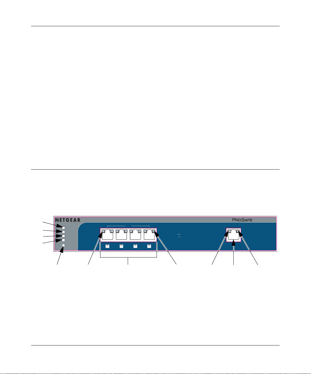
Front Panel Features
The ProSafe Wireless-N VPN Firewall front panel shown below includes two groups of RJ-45
connectors and a column of status indicator light-emitting diodes (LEDs), including Power, Test,
and Band lights:
Figure 1-1New Photo
The column of status indicator light-emitting diodes (LEDs) on the left and the RJ-45 LEDs are
described in Table 1-1., “LED Descriptions”.
Introduction 1-9
v1.0, July 2008
Page 24

ProSafe Wireless-N VPN Firewall SRXN3205 Reference Manual
1. Factory Defaults button. (5)
Using a sharp object, press and hold this button for about ten seconds until the front panel
TEST light flashes to reset the VPN firewall to factory default settings. All configuration
settings will be lost and the default password will be restored.
2. LAN Ethernet ports. (6)
Four switched N-way automatic speed negotiating, Auto MDI/MDIX, Gigabit Ethernet ports
with RJ-45 connectors.
3. WAN Ethernet port. (7)
One independent N-way automatic speed negotiating, Auto MDI/MDIX, Gigabit Ethernet port
with a RJ-45 connector.
The function of each LED is described in the following table:
Table 1-1. LED Descriptions
Item LED Activity Description
1PWR
(Power)
2 TEST On (Amber)
3 n/a 5 GHz Wireless LAN 802.11n/a Link Activity Indicator (5 GHz)
4 n/g 2.4 GHz Wireless LAN 802.b/g/n Link Activity Indicator (2.4 GHz) (Default)
6 LAN Ports
7 WAN Port
8 LINK/ACT
(Link and
Activity)
9 SPEED On (Green)
On (Green)
Off
Blinking
(Amber)
Off
Off Indicates WLAN 802.11n/a (5GHz) mode is disabled.
Blink (Green) Indicates Wireless data traffic in 5GHz modes.
Off Indicates WLAN 802.11b/g/n (2.4 GHz) mode is disabled.
Blink (Green) Indicates Wireless data traffic in 2.4 GHz modes
On (Green)
Blinking (Green)
Off
On (Amber)
Off
Power is supplied to the VPN firewall.
Power is not supplied to the VPN firewall.
Test mode: The system is initializing (On) or the initialization has
failed (Blinking).
Writing to Flash memory (during upgrading or resetting to defaults).
The system has booted successfully.
The WAN/LAN port has detected a link with a connected Ethernet
device.
Data is being transmitted or received by the WAN/LAN port.
The WAN/LAN port has no link.
The WAN/LAN port is operating at 1,000 Mbps.
The WAN/LAN port is operating at 100 Mbps.
The WAN/LAN port is operating at 10 Mbps.
1-10 Introduction
v1.0, July 2008
Page 25
ProSafe Wireless-N VPN Firewall SRXN3205 Reference Manual
1
1
1
2
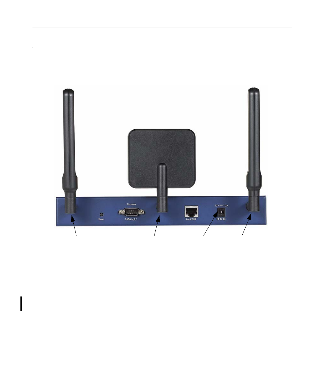
Rear Panel Features
The rear panel of the ProSafe Wireless-N VPN Firewall includes three SMA dual-band an tenna
connectors (2 dipole (long); 1 patch (square) and AC-DC power adapter jack.
Figure 1-2 New Photo
The SRXN3205 rear panel functions are described below:
1. Left, Middle, and Right Detachable (SMA) Antennas (1)
The SRXN3205 provides three SMA connectors for the detachable antennas (two dipole and
one patch). For the best performance, attach the patch antenna to the middle connector and
attach the dipole antennas to the two connectors on both corners. The three antennas can be
positioned horizontally or vertically for the best coverage.
2. DC Power Jack (2)
This jack connects to the SRXN3205 12V 1.5A AC-DC power adapter.
Introduction 1-11
v1.0, July 2008
Page 26
ProSafe Wireless-N VPN Firewall SRXN3205 Reference Manual
IP Address
User Name
Password
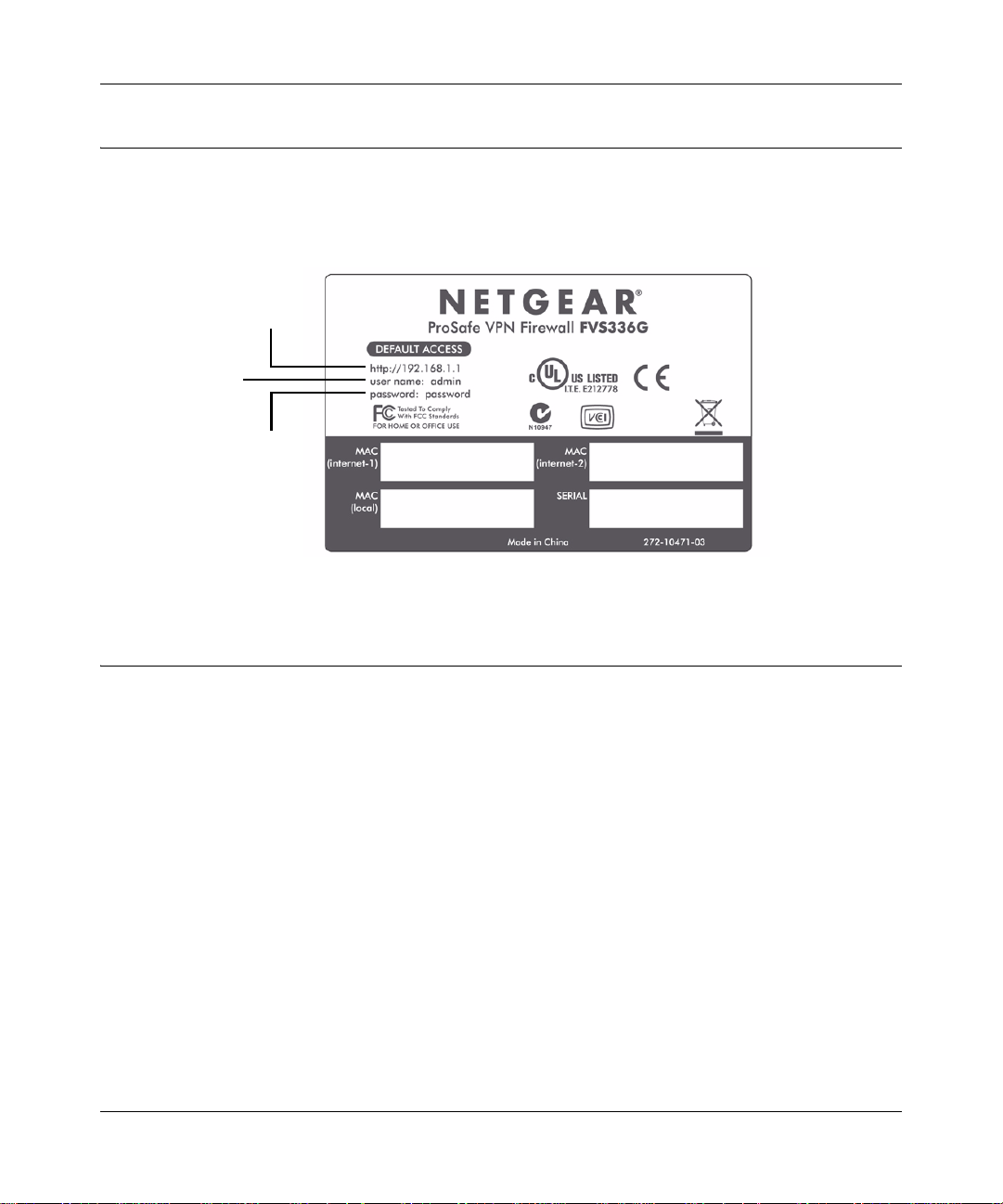
Default IP Address, Login Name, and Password Location
Check the label on the bottom of the SRXN3205’s enclosure if you need a reminder of the
following factory default information:
Figure 1-3New Drawing
Qualified Web Browsers
To configure the ProSafe Wireless-N VPN Firewall, an administrator must use Internet Explorer
5.1 or higher, Apple Safari 1.2 or higher, or Mozilla Firefox l.x Web browser with JavaScript,
cookies, and SSL enabled.
Although these web browsers are qualified for use with the VPN firewall’s Web Management
Interface for configuring the VPN firewall, SSL VPN users should choose a browser that supports
JavaScript, Java, cookies, SSL, and ActiveX to take advantage of the full suite of applications.
Note that Java is only required for the SSL VPN portal, not the Web Management Interface.
1-12 Introduction
v1.0, July 2008
Page 27

ProSafe Wireless-N VPN Firewall SRXN3205 Reference Manual
Chapter 2
Connecting to the Internet (WAN)
The initial Internet configuration of the SRXN3205 ProSafe Wireless-N VPN Firewall is described
in this chapter.
This chapter contains the following sections:
• “Understanding the Connection Steps”
• “Logging into the VPN Firewall”
• “Navigating the Menus”
• “Configuring the Internet Connection (WAN)”
• “Configuring Dynamic DNS (Optional)”
• “Configuring the Advanced WAN Options (Optional)”
Understanding the Connection S teps
Typically, six steps are required to complete the basic Internet connection of your firewall.
1. Connect the firewall physically to your network. Connect the cables and restart your
network according to the instructions in the installation guide. See the Installation Guide,
SRXN3205 ProSafe Wireless-N VPN Firewall for complete steps. A PDF of the Installation
Guide is on the NETGEAR web site at: http://kbserver.netgear.com.
2. Log in to the VPN Firewall. After logging in, you are ready to set up and configure your
firewall. You can also change your password and enable remote management at this time. See
“Logging into the VPN Firewall” on page 2-2.
3. Configure the Internet connections to your ISP(s). During this phase, you will connect to
your ISPs. You can also program the WAN traffic meters at this time if desired. See
“Configuring the Internet Connection (WAN)” on page 2-4.
4. Configure dynamic DNS on the WAN port (optional). Configure your fully qualified
domain names during this phase (if required). See “Configuring Dynamic DNS (Optional)” on
page 2-12.
Connecting to the Internet (WAN) 2-1
v1.0, July 2008
Page 28
ProSafe Wireless-N VPN Firewall SRXN3205 Reference Manual
5. Configure the WAN options (optional). Optionally, you can enable the WAN port to respond
to a ping, and you can change the factory default MTU size and port speed. However, these are
advanced features and changing them is not usually required. See “Configuring the Advanced
WAN Options (Optional)” on page 2-14.
Each of these tasks is detailed separately in this chapter. The configuration of firewall, VPN, and
Wireless features are described in later chapters.
Logging into the VPN Firewall
To connect to the VPN firewall, your computer needs to be configured to obtain an IP address
automatically from the VPN firewall by DHCP. For instructions on how to configure your
computer for DHCP, refer to the link in Appendix B, “Related Documents.
To connect and log in to the firewall follow these steps:
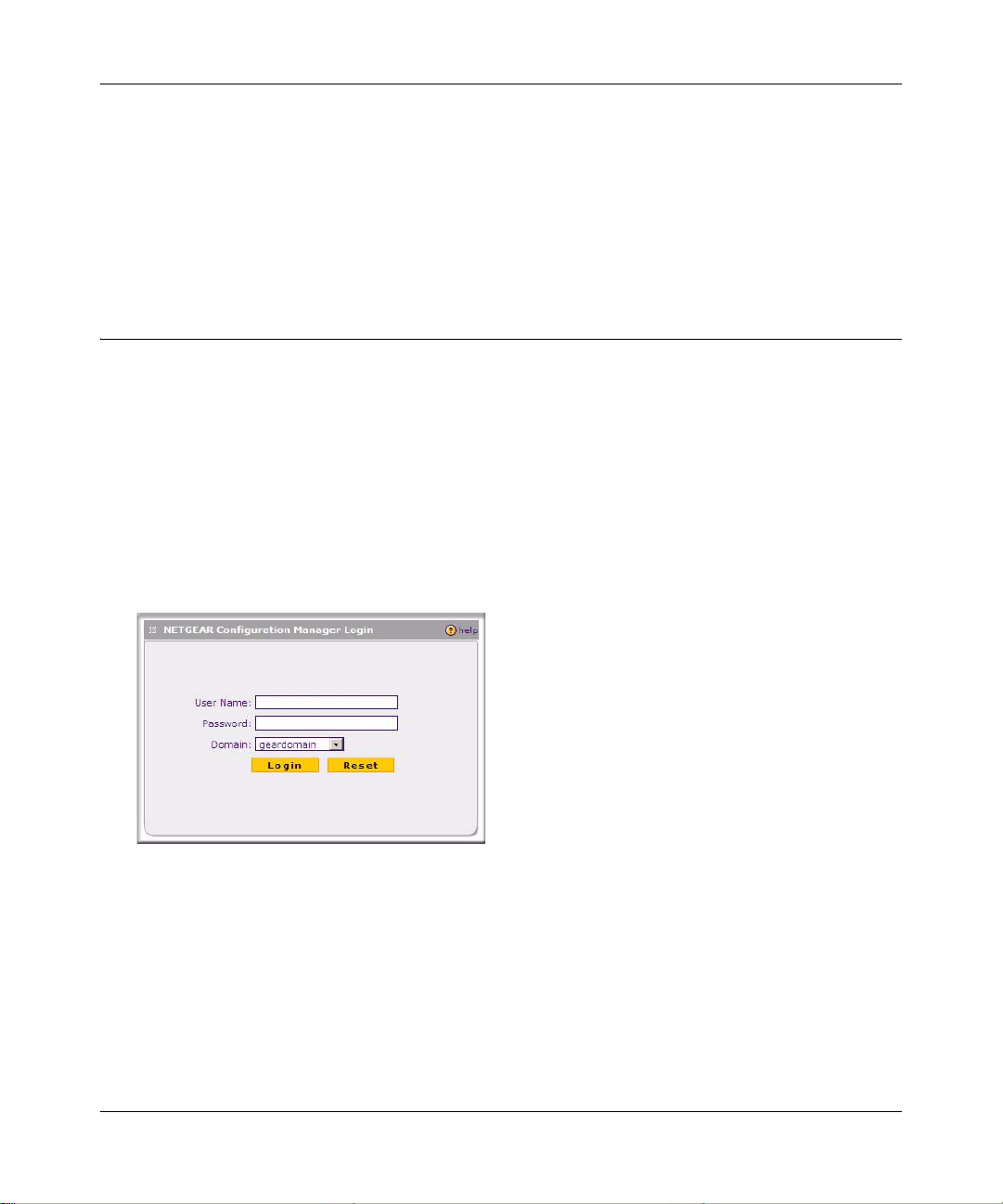
1. Start any of the qualified browsers, as detailed in “Qualified Web Browsers” on page 1-12.
2. Enter https://192.168.1.1 in the address field.
The Manager login features appear in the browser.
Figure 2-1 OK
3. In the User field, type admin in lower case.
Use all lower case letters since both login fields are case sensitive.
4. In the Password field, type password in lower case.
5. Click Login.
2-2 Connectin g to the Internet (WAN)
v1.0, July 2008
Page 29
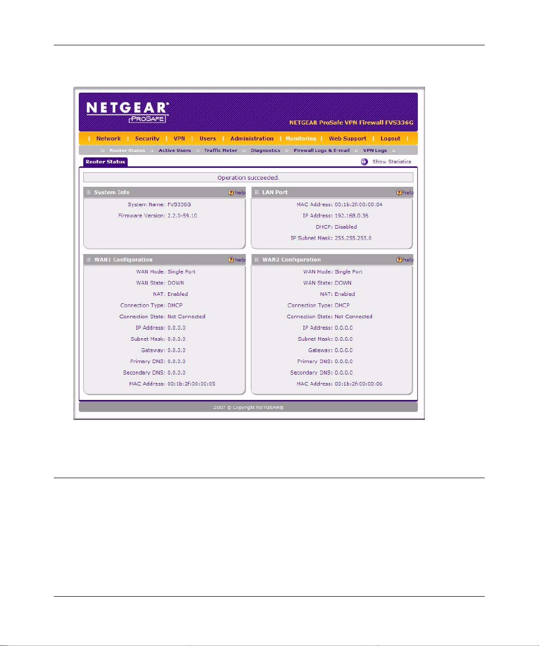
ProSafe Wireless-N VPN Firewall SRXN3205 Reference Manual
The Web Configuration Manager appears, displaying the Router Status menu as the default.
Figure 2-2 new screen shot
Navigating the Menus
The Web Configuration Manager menus are organized in a layered structure of main categories
and submenus:
• Main menu. The horizontal orange bar near the top of the page is the main menu, containing
the primary configuration categories. Clicking on a primary category changes the contents of
the submenu bar.
Connecting to the Internet (WAN) 2-3
v1.0, July 2008
Page 30
ProSafe Wireless-N VPN Firewall SRXN3205 Reference Manual
• Submenu. The horizontal grey bar immediately below the main menu is the submenu,
containing subcategories of the currently selected primary category.
• Tab. Immediately below the submenu bar, at the top of the menu active window, are one or
more tabs, further subdividing the currently selected subcategory if necessary.
• Option arrow . To the right of the tabs on some menus are one or more blue dots with an arrow
in the center . Clicking an option arrow brings up either a popup window or an advanced op tion
menu.
Tip: In the instructions in this guide, we may refer to a menu using the notation
primary > subcategory, such as Network Configuration > WAN Settings. In
this example, Network Configuration is the selected primary category (in the
main menu) and WAN Settings is the selected subcategory (in the submenu).
You can now proceed to the first configuration task, configuring the firewall’s Internet
connections.
Configuring the Internet Connection (WAN)
To set up your firewall for secure Internet connections, you configure the WAN port. The Web
Configuration Manager offers two connection configuration options:
• Automatic detection and configuration of the network connection.
• Manual configuration of the network connection.
Each option is detailed in the following sections.
Automatically Detecting and Connecting
To automatically configure the WAN port for connection to the Internet:
1. Select Network Configuration > WAN Settings from the menu/submenu.
The WAN tabs appear on screen with the WAN ISP Settings tab in view.
2-4 Connectin g to the Internet (WAN)
v1.0, July 2008
Page 31

ProSafe Wireless-N VPN Firewall SRXN3205 Reference Manual
Figure 2-3 New screen shot
2. Click Auto Detect at the bottom of the menu.
Auto Detect will probe the WAN port for a range of connection method s and suggest one that
your ISP appears to support.
a. If Auto Detect is successful, a status bar at the top of the menu will display the results:.
Figure 2-4 New screen shot
Connecting to the Internet (WAN) 2-5
v1.0, July 2008
Page 32

ProSafe Wireless-N VPN Firewall SRXN3205 Reference Manual
b. If Auto Detect senses a connection method that requires input from you, it will prompt yo u
for the information. All methods with the required settings are detailed in the following
table.
Table 2-1. Internet connection methods
Connection Method Data Required
DHCP (Dynamic IP) No data is required.
PPPoE Login (Username, Password);
Account Name, Domain Name (sometimes required).
PPTP Login (Username, Password),
Local IP address, and PPTP Server IP address;
Account Name (sometimes required).
Fixed (Static) IP Static IP address, Subnet, and Gateway IP; DNS Server IP addresses.
c. If Auto Detect does not find a connection, you will be prompted to (1) check the physical
connection between your firewall and the cable or DSL line, or to (2) check your firewall’s
MAC address (For more information, see “Configuring the WAN Mode (Required for
Dual WAN)” on page 2-11 and “Troubleshooting the ISP Connection” on page 12-4).
3. To verify the connection, click the WAN Status option arrow at the top right of the screen.
A popup window appears, displaying the connection status of the WAN port.
Figure 2-5 New screen shot
2-6 Connectin g to the Internet (WAN)
v1.0, July 2008
Page 33

ProSafe Wireless-N VPN Firewall SRXN3205 Reference Manual
The WAN Status window should show a valid IP address and gateway. If the configuration
was not successful, skip ahead to “Manually Configuring the Internet Connection” following
this section, or see “Troubleshooting the ISP Connection” on page 12-4.
Note: If the configuration process was successful, you are connected to the Internet
through the WAN port.
4. If your WAN ISP configuration was successful, you can test the internet connection, or skip
ahead to..........
5. Click Test to evaluate your entries.
The firewall will attempt to connect to the NETGEAR Web site. If a successful connection is
made, NETGEAR’s Web site appears.
If your WAN ISP configuration was successful, you can skip ahead to “Configuring the WAN
Mode (Required for Dual WAN)” on page 2-11.
If the automatic WAN ISP configurations failed, you can attempt a manual configuration as
described in the following section, or see “Troubleshooting the ISP Connection” on page 12-4.
Manually Configuring the Internet Connection
Unless your ISP automatically assigns your configuration automatically via DHCP, you will need
to obtain configuration parameters from your ISP in order to manually establish an Internet
connection. The necessary parameters for various connection types are listed in Table 2-1.
To manually configure your WAN ISP Settings:
1. Select Network Configuration> WAN ISP Settings and enter the following:
2. In the ISP Login options, choose one of these options:
• If your ISP requires an initial login to establish an Internet connection, click Yes (this is
the default).
• If a login is not required, click No and ignore the Login and Password fields.
Figure 2-6 OK
Connecting to the Internet (WAN) 2-7
v1.0, July 2008
Page 34

ProSafe Wireless-N VPN Firewall SRXN3205 Reference Manual
3. If you clicked Yes, enter the ISP-provided Login and Password information.
4. In the ISP Type options, select the type of ISP connection you use from the three listed
options. (By default, “Other (PPPoE)” is selected, as shown below.
Figure 2-7 New screen shot
(If your connection is PPPoE, PPTP or BigPond Cable, your ISP will require an initial login.)
5. If you have installed login software such as WinPoET or Enternet, then your connection type
is PPPoE. If your ISP uses PPPoE as a login protocol:
a. Select Other (PPPoE).
Figure 2-8 New screen shot
b. Configure the following fields:
• Account Name. Valid account name for the PPPoE connection
• Domain Name. Name of your ISP’s domain or your domain name if your ISP has
assigned one. In most cases, you may leave this field blank.
• Idle Timeout. Select Keep Connected, to keep the connection always on. To logout
after the connection is idle for a period of time, click Idle Time and in the timeout field
enter the number of minutes to wait before disconnecting.
2-8 Connectin g to the Internet (WAN)
v1.0, July 2008
Page 35

ProSafe Wireless-N VPN Firewall SRXN3205 Reference Manual
6. If your ISP is Austria Telecom or any other ISP that uses PPTP as a login protocol:
a. Select Austria (PPTP).
b. Configure the following fields:
• Account Name (also known as Host Name or System Name). Enter the valid account
name for the PPTP connection (usually your e-mail name as assigned by your ISP).
Some ISPs require entering your full email address here.
• Domain Name. Your domain name or workgroup name assigned by your ISP, or your
ISPs domain name. You may leave this field blank.
• Idle Timeout. Check the Keep Connected radio box to keep the connection always
on. T o logout after the connection is idle for a period of time, click Idle T ime and enter
the number of minutes to wait before disconnecting in the timeout field. This is useful
if your ISP charges you based on the amount of time you have logged in.
• My IP Address. IP address assigned by the ISP to make the connection with the ISP
server.
• Server IP Address. IP address of the PPTP server.
7. If your ISP is Telstra BigPond Cable:
a. Select BigPond Cable.
b. Configure the Login Server and Idle Timeout fields.
The Login Server is the IP address of the local BigPond Login Server in your area.
8. Review the Internet (IP) Address options.
Figure 2-9
These options are inactive if BigPond Cable is selected???.
9. If your ISP has assigned a fixed (static) IP address, select Use Static IP Address, and
configure the following fields:
Connecting to the Internet (WAN) 2-9
v1.0, July 2008
Page 36

ProSafe Wireless-N VPN Firewall SRXN3205 Reference Manual
• IP Address. Enter the Static IP address assigned to you, that identifies the firewall to your
ISP.
• Subnet Mask. Enter the mask provided by the ISP or your network administrator.
• Gateway IP Address. Enter the IP address of the ISP’s gateway, provided by the ISP or
your network administrator.
10. If your ISP has not assigned a static IP address, click Get dynamically from ISP. The text
fields will be inactivated.
The ISP will automatically assign an IP address to the firewall using DHCP network protocol.
11. Review the Domain Name Server (DNS) Servers options.
Figure 2-10 OK
• If your ISP has not assigned any Domain Name Servers (DNS) addresses, click Get
dynamically from ISP.
• If your ISP (or your IT department) has assigned DNS addresses, click Use these DNS
Servers and enter the DNS server IP addresses provided to you in the fields.
12. Click Apply to save any changes to the WAN ISP Settings. (Or click Reset to discard any
changes and revert to the previous settings.)
13. Click Test to evaluate your entries.
The firewall will attempt to connect to the NETGEAR Web site. If a successful connection is
made, NETGEAR’s Web site appears.
When you are finished, click Logout or proceed to additional setup and management tasks.
2-10 Connecting to the Internet (WAN)
v1.0, July 2008
Page 37

ProSafe Wireless-N VPN Firewall SRXN3205 Reference Manual
Configuring the WAN Mode
T o access the WAN Mode, click on Network Configuration > WAN Settings and select the W AN
Mode tab.
The WAN mode page allows you to configure how your firewall uses the external Internet
connection. This screen gives you two choices for accessing the external Internet connection.
• Network Address Translation (NAT). This technique allows several computers on a
LAN to share the same Internet connection (IP address) while using private IP address on
the LAN, which are hidden from the Internet.
• Classical Routing. This method allows the firewall to perform the routing, but requires
separate valid static Internet IP address for each PC on your LAN.
Network Address Translation
Network Address Translation (NAT) allows all PCs on your LAN to share a single public Internet
IP address. From the Internet, there is only a single device (the firewall) and a single IP address.
PCs on your LAN can use any private IP address range, and these IP addresses are not visible from
the Internet.
• The firewall uses NAT to select the correct PC (on your LAN) to receive any incoming data.
• If you only have a single public Internet IP address, you MUST use NAT. (the default setting).
• If your ISP has provided you with multiple public IP addresses, you can use one address as the
primary shared address for Internet access by your PCs, and you can map incoming traffic on
the other public IP addresses to specific PCs on your LAN. This one-to-one inbound mapping
is configured using an inbound firewall rule.
Classical Routing
In classical routing mode, the firewall performs routing, but without NAT. To gain Internet access,
each PC on your LAN must have a valid static Internet IP address.
If your ISP has allocated a number of static IP addresses to you, and you have assigned one of
these addresses to each PC, you can choose classical routing. Or, you can use classical routing for
routing private IP addresses within a campus environment.
To learn the status of the WAN port, you can v ie w the Router Status page (see “Monitoring VPN
Tunnel Connection Status” on page 11-15) or look at the LEDs on the front panel (see “Front Panel
Features” on page 1-9).
Connecting to the Internet (WAN) 2-11
v1.0, July 2008
Page 38

ProSafe Wireless-N VPN Firewall SRXN3205 Reference Manual
Configuring Dynamic DNS (Optional)
Dynamic DNS (DDNS) is an Internet service that allows routers with varying public IP addresses
to be located using Internet domain names. To use DDNS, you must setup an account with a
DDNS provider such as DynDNS.org, TZO.com or Iego.net. Links to DynDNS, TZO and Iego are
provided for your convenience as Tabbed menus xxx to the Dynamic DNS configuration screen.
The firewall firmware includes software that notifies dynamic DNS servers of changes in the
WAN IP address, so that the services running on this network can be accessed by others on the
Internet.
If your network has a permanently assigned IP address, you can register a domain name and have
that name linked with your IP address by public Domain Name Servers (DNS). However, if your
Internet account uses a dynamically assigned IP address, you will not know in advance what your
IP address will be, and the address can change frequently—hence, the need for a commercial
DDNS service, which allows you to register an extension to its domain, and restores DNS requests
for the resulting FQDN to your frequently-changing IP address.
After you have configured your account information in the firewall, whenever your ISP-assigned
IP address changes, your firewall will automatically contact your DDNS service provider, log in to
your account, and register your new IP address.
{{{
• For auto-rollover mode, you will need a fully qualified domain name (FQDN) to implement
features such as exposed hosts and virtual private networks regardless of whether you have a
fixed or dynamic IP address.
• For load balancing mode, you may still need a fully qualified domain name (FQDN) either for
convenience or if you have a dynamic IP address. }}}}}
Note: If your ISP assigns a private WAN IP address such as 192.168.x.x or 10.x.x.x, the
dynamic DNS service will not work because private addresses will not be routed
on the Internet.
2-12 Connecting to the Internet (WAN)
v1.0, July 2008
Page 39

ProSafe Wireless-N VPN Firewall SRXN3205 Reference Manual
To configure Dynamic DNS:
1. Select Network Configuration > Dynamic DNS from the main/submenu.
The Dynamic DNS screen displays.
Figure 2-11 Need new screenshots (3)
The Current WAN Mode section reports the currently configured WAN mode. Only those
options that match the configured WAN Mode will be accessible.
2. Select the Dynamic DNS Service you will use. {{{Need 3 new Screenshots and
descriptions}}}
The fields corresponding to the selection you have chosen will be activated. Each DDNS
service provider requires its own parameters.
Connecting to the Internet (WAN) 2-13
v1.0, July 2008
Page 40

ProSafe Wireless-N VPN Firewall SRXN3205 Reference Manual
3. Access the Web site of one of the DDNS service providers and set up an account. Links to
three DDNS providers are in the tab header.
Figure 2-12 Need new screen shots (3)
4. After registering for your account, return to the Dynamic DNS menu and fill in the required
fields for the DDNS service you selected:
a. In the Host and Domain Name field, enter the entire FQDN name that your dynamic DNS
service provider gave you (for example: <yourname>.dyndns.org).
b. Enter the User Name, User email Address, or Account Name requested by the DDNS
Service to identify you when logging into your DDNS account.
c. Enter the Password, or User Key, for your DDNS account.
d. If your dynamic DNS provider allows the use of wildcards in resolving your URL, check
Use wildcards to activate this feature.
For example, the wildcard feature will cause anything.yourhost.dyndns.org to be aliased
to the same IP address as yourhost.dyndns.org
e. If your dynamic DNS provider requires you to renew your account monthly, check
Update every 30 days to have the firewall renew the account automatically.
5. Click Apply to save your configuration.
Configuring the Advanced WAN Options (Optional)
To configure the Advanced WAN options:
1. Select Network Configuration > WAN Settings from the main/submenu.
The WAN ISP Settings screen displays.
2-14 Connecting to the Internet (WAN)
v1.0, July 2008
Page 41

ProSafe Wireless-N VPN Firewall SRXN3205 Reference Manual
2. Click the Advanced link to the right of the tabs. The WAN Advanced Options tab is
displayed.
Figure 2-13 Need new screenshot
3. Edit the default information you want to change.
a. MTU Size. The normal MTU (Maximum Transmit Unit) value for most Ethernet
networks is 1500 Bytes, or 1492 Bytes for PPPoE connections. For some ISPs, you may
need to reduce the MTU. This is rarely required, and should not be done unless you are
sure it is necessary for your ISP connection.
b. Port Speed. In most cases, your firewall can automatically determine the connection
speed of the WAN port. If you cannot establish an Internet connection and the WAN Link
or Speed LED blinks continuously, you may need to manually select the port speed.
AutoSense is the default.
If you know the Ethernet port speed that your broadband modem supports, select it;
otherwise, select 10M. Use the half-duplex settings unless you are sure your broadband
modem supports full duplex.
c. Router's MAC Address. Each computer or router on your network has a unique 32-bit
local Ethernet address. This is also referred to as the computer's MAC (Media Access
Control) address. The default is Use default address. However, if your ISP requires MAC
authentication, then select either of these options:
• Use this Computer's MAC address to have the firewall use the MAC address of the
computer you are now using, or
• Use This MAC Address to manually type in the MAC address that your ISP expects.
Connecting to the Internet (WAN) 2-15
v1.0, July 2008
Page 42

ProSafe Wireless-N VPN Firewall SRXN3205 Reference Manual
The format for the MAC address is 01:23:45:67:89:AB (numbers 0-9 and either uppercase
or lowercase letters A-F). If you select Use This MAC Address and then type in a MAC
address, your entry will be overwritten.
4. Click Apply to save your changes.
Additional WAN Related Configuration
• If you want the ability to manage the firewall remotely , enable remote mana gement at this time
(see “Enabling Remote Management Access” on page 9-10). If you enable remote
management, we strongly recommend that you change your password (see “Changing
Passwords and Administrator Settings” on page 9-8).
• At this point, you can set up the traffic meter for the WAN, if desired. See “Enabling the
Traffic Meter” on page 11-1.
2-16 Connecting to the Internet (WAN)
v1.0, July 2008
Page 43

ProSafe Wireless-N VPN Firewall SRXN3205 Reference Manual
Chapter 3
LAN Configuration
This chapter describes how to configure the advanced LAN features of your ProSafe Wireless-N
VPN Firewall.
This chapter contains the following sections:
• “Using the VPN Firewall as a DHCP Server” on page 3-1
• “Managing Groups and Hosts (LAN Groups)” on page 3-5
• “Configuring DHCP Address Reservation” on page 3-9
• “Configuring Multi Home LAN IP Addresses” on page 3-10
• “Configuring Static Routes” on page 3-11
• “Configuring Routing Information Protocol (RIP)” on page 3-13
Using the VPN Firewall as a DHCP Server
By default, the VPN Firewall will function as a DHCP (Dynamic Host Configuration Protocol)
server, allowing it to assign IP, DNS server, WINS Server, and default gateway addresses to all
computers connected to the LAN. The assigned default gateway address is the LAN address of the
VPN Firewall. IP addresses will be assigned to the attached PCs from a pool of addresses specified
in this menu. Each pool address is tested before it is assigned to avoid duplicate addresses on the
LAN.
For most applications, the default DHCP and TCP/IP settings of the VPN Firewall are satisfactory.
See the link to “Preparing a Computer for Network Access” in Appendix B, “Related Documents”
for an explanation of DHCP and information about how to assign IP addresses for your network.
If another device on your network will be the DHCP server, or if you will manually configure the
network settings of all of your computers, clear the Enable DHCP server radio box by clicking
the Disable DHCP Server radio box. Otherwise, leave it checked.
Specify the pool of IP addresses to be assigned by setting the Starting IP Address and Ending IP
Address. These addresses should be part of the same IP address subnet as the VPN Firewall’s LAN
IP address. Using the default addressing scheme, you would define a range between 192.168.1.2
LAN Configuration 3-1
v1.0, July 2008
Page 44

ProSafe Wireless-N VPN Firewall SRXN3205 Reference Manual
and 192.168.1.100, although you may wish to save part of the range for devices with fixed
addresses.
The VPN Firewall will deliver the following parameters to any LAN device that requests DHCP:
• An IP Address from the range you have defined.
• Subnet Mask
• Gateway IP Address (the VPN Firewall’s LAN IP address).
• Primary DNS Server (the VPN Firewall’s LAN IP address or a user-specified DNS server IP
address in the LAN Setup menu).
• Secondary DNS Server (if you entered a secondary DNS server IP address in the LAN Setup
menu).
• WINS Server (if you entered a WINS server IP address in the LAN Setup menu).
• Lease Time (date obtained and duration of lease).
Configuring the LAN Setup Options
The LAN Setup menu allows configuration of LAN IP services such as DHCP and allows you to
configure a secondary or “multi-home” LAN IP setup on the LAN. The default values are suitable
for most users and situations. These are advanced settings usually configured by a network
administrator.
To modify your LAN setup, follow these steps:
1. Select Network Configuration > LAN Settings from the main/sub-menu.
The LAN Settings tabs (LAN Setup, LAN Groups, and LAN Multi-homing) are displayed
with LAN Setup as the default tab.
3-2 LAN Configuration
v1.0, July 2008
Page 45

.
Figure 3-1OK
ProSafe Wireless-N VPN Firewall SRXN3205 Reference Manual
2. In the LAN TCP/IP Setup section, configure the following settings:
• IP Address. The LAN address of your VPN Firewall (factory default: 192.168.1.1).
Note: If you change the LAN IP address of the firewall while connected through the
browser, you will be disconnected. You must then open a new connection to
the new IP address and log in again. For example, if you change the default IP
address 192.168.1.1 to 10.0.0.1, you must now enter https://10.0.0.1 in your
browser to reconnect to the Web Configuration Manager.
• IP Subnet Mask. The subnet mask specifies the network number portion of an IP address.
Your VPN Firewall will automatically calculate the subnet mask based on the IP address
that you assign. Unless you are implementing subnetting, use 255.255.255.0 as the subnet
mask.
3. In the DHCP section, leave the DNCP enabled, or select Disable DHCP Server.
• The VPN Firewall will function as a DHCP server (default), providing TCP/IP
configuration settings for all the computers connected to the VPN Firewall's LAN.
LAN Configuration 3-3
v1.0, July 2008
Page 46

ProSafe Wireless-N VPN Firewall SRXN3205 Reference Manual
• If another device on your network will be the DHCP server, or if you will manually
configure all devices, click Disable DHCP Server.
If the DHCP server is enabled, enter the following parameters:
• Domain Name. (Optional) The DHCP will assign the entered domain to its DHCP clients.
• Starting IP Address. Specifies the first of the contiguous addresses in the IP address pool.
Any new DHCP client joining the LAN will be assigned an IP address between this
address and the Ending IP Address. The IP address 192.168.1.2 is the default start address.
• Ending IP Address. Specifies the last of the contiguous addresses in the IP address pool.
The IP address 192.168.1.100 is the default ending address.
Note: The Starting and Ending DHCP addresses should be in the same subnet as
the LAN IP address of the VPN Firewall (the IP Address configured in the
LAN TCP/IP Setup section).
• Primary DNS Server. (Optional) If an IP address is specified, the VPN Firewall will
provide this address as the primary DNS server IP address. If no address is specified, the
VPN Firewall will provide its own LAN IP address as the primary DNS server IP address.
• Secondary DNS Server. (Optional) If an IP address is specified, the VPN Firewall will
provide this address as the secondary DNS server IP address.
• WINS Server. (Optional) Specifies the IP address of a local Windows Ne tBios Server if
one is present in your network.
• Lease Time. Specifies the duration for which a DHCP-provided IP address will be leased
to a client.
• Enable DNS Proxy . When DNS proxy is enabled (default), the DHCP server will provide
the SRXN3205 LAN IP address as the DNS server for address name resolution. If this box
is unchecked, the DHCP server will provide the ISP’ s DNS server IP addresses. The VPN
Firewall will still service DNS requests sent to its LAN IP address unless you disable DNS
Proxy in the DHCP settings (see “Attack Checks” on page 5-10).
4. Click Apply to save your settings.
Note: Once you have completed the LAN setup, all outbound traffic is allowed and
all inbound traffic is discarded. To change these default traffic rules, refer to
Chapter 5, “Firewall Security and Content Filtering.
3-4 LAN Configuration
v1.0, July 2008
Page 47

ProSafe Wireless-N VPN Firewall SRXN3205 Reference Manual
Managing Groups and Hosts (LAN Groups)
The Known PCs and Devices table in the LAN Groups menu contains a list of all known PCs
and network devices that are assigned dynamic IP addresses by the VPN Firewall, or have been
discovered by other means. Collectively, these entries make up the LAN Groups Database.
The LAN Groups Database is updated by these methods:
• DHCP Client Requests. By default, the DHCP server in this VPN Firewall is enabled, and
will accept and respond to DHCP client requests from PCs and other network devices. These
requests also generate an entry in the LAN Groups Database. Because of this, leaving the
DHCP server feature (LAN Setup tab) enabled is strongly recommended.
• Scanning the Network. The local network is scanned using ARP requests. The ARP scan will
detect active devices that are not DHCP clients. However, sometimes the name of the PC or
device cannot be accurately determined, and will appear in the database as Unknown.
• Manual Entry. You can manually enter information about a network device.
Some advantages of the LAN Groups Database are:
• Generally, you do not need to enter IP addresses or MAC addresses. Instead, you can just
select the desired PC or device.
• No need to reserve an IP address for a PC in the DHCP server. All IP address assignments
made by the DHCP server will be maintained until the PC or device is removed from the
database, either by expiry (inactive for a long time) or by you.
• No need to use a fixed IP on PCs. Because the address allocated by the DHCP server will
never change, you don't need to assign a fixed IP to a PC to ensure it always has the same IP
address.
• MAC level control over PCs. The LAN Groups Database uses the MAC address to identify
each PC or device. So changing a PC’s IP address does not affect any restrictions on that PC.
• Group and individual control over PCs.
– You can assign PCs to Groups and apply restrictions to each Group using the Firewall
Rules screen (see “Using Rules & Services to Block or Allow Traffic” on page 5-2).
– You can also select the Groups to be covered by th e Block Sites feature (see “Setting
Block Sites (Content Filtering)” on page 5-21).
– If necessary, you can also create Firewall Rules to apply to a single PC (see “Enabling
Source MAC Filtering (Address Filter)” on page 5-24). Because the MAC address is used
to identify each PC, users cannot avoid these restrictions by changing the IP address.
LAN Configuration 3-5
v1.0, July 2008
Page 48

ProSafe Wireless-N VPN Firewall SRXN3205 Reference Manual
• A computer is identified by its MAC address—not its IP address. Hence, changing a
computer’s IP address does not affect any restrictions applied to that PC.
Viewing the LAN Group s Database
To view the LAN Groups Database, follow these steps:
1. Select Network Configuration > LAN Settings from the main/sub-menu.
The LAN Setup tab displays.
2. Click the LAN Groups tab and the LAN Groups tab displays.
Figure 3-2Ok
The Known PCs and Devices table lists the entries in the LAN Groups Database. For each
computer or device, the following fields are displayed:
• Name. The name of the PC or device. For computers that do not support the NetBIOS
protocol, this will be listed as “Unknown” (you can edit the entry manually to add a
meaningful name). If the computer was assigned an IP address by the DHCP server, then the
Name will be appended by an asterisk.
• IP Address. The current IP address of the computer. For DHCP clients of the VPN Firewall,
this IP address will not change. If a computer is assigned a static IP addresses, you will need to
update this entry manually if the IP address on the computer has been changed.
• MAC Address. The MAC address of the PC’s network interface.
3-6 LAN Configuration
v1.0, July 2008
Page 49

ProSafe Wireless-N VPN Firewall SRXN3205 Reference Manual
• Group. Each PC or device can be assigned to a single group. By default, a computer is
assigned to Group 1, unless a different group is chosen from the Group pull-down menu.
• Action. Allows modification of the selected entry by clicking Edit.
Adding Devices to the LAN Groups Database
To add devices manually to the LAN Groups Database, follow these steps:
1. In the Add Known PCs and Devices section, make the following entries:
• Name. Enter the name of the PC or device.
• IP Address Type. From the pull-down men u, choose how this device receives its IP
address. The choices are:
– Fixed (Set on PC). The IP address is statically assigned on the computer.
– Reserved (DHCP Client). Directs the VPN Firewall’s DHCP server to always assign
the specified IP address to this client during the DHCP negotiation.
Note: When assigning a Reserved IP address to a client, the IP address selected must
be outside the range of addresses allocated to the DHCP server pool.
• IP Address. Enter the IP address that this computer or device is assigned in the IP
Address field. If the IP Address Type is Reserved (DHCP Client), the VPN Firewall will
reserve the IP address for the associated MAC address.
• MAC Address. Enter the MAC address of the computer’s network interface in the MAC
Address field. The MAC address format is six colon-separated pairs of hexadecimal
characters (0-9 and A-F), such as 01:23:45:67:89:AB.
• Group. From the pull-down menu, select the LAN Group to which the computer will be
assigned. (Group 1 is the default group.)
2. Click Add. The device will be added to the Known PCs and Devices table.
LAN Configuration 3-7
v1.0, July 2008
Page 50

ProSafe Wireless-N VPN Firewall SRXN3205 Reference Manual
Changing Group Names in the LAN Groups Database
By default, the LAN Groups are named Group1 through Group8. You can rename these group
names to be more descriptive, such as Engineering or Marketing.
To edit the names of any of the eight available groups:
1. From the LAN Groups tab, click the Edit Group Names link to the right of the tabs.
The Network Database Group Names tab appears.
Figure 3-3OK
2. Select the radio button next to any group name to make that name active for editing.
3. Type a new name in the field.
4. Click Apply to save your setting, each time you change a name in the field. {{Possible bug}}
5. Select and edit other group names if desired.
6. Click Apply to save each field change.
3-8 LAN Configuration
v1.0, July 2008
Page 51

ProSafe Wireless-N VPN Firewall SRXN3205 Reference Manual
Configuring DHCP Address Reservation
A computer (or device) will always receive the same IP address, if you specify a reserved IP
address for the computer (or device) on the LAN (based on the MAC address of the device), each
time it accesses the VPN Firewall’s DHCP server. Reserved IP addresses should be assigned to
servers or access points that require permanent IP address settings. The Reserved IP address that
you select must be outside of the DHCP Server pool.
To reserve an IP address, manually enter the device in the LAN Groups tab, specifying Reserved
(DHCP Client), as described in “Adding Devices to the LAN Groups Database” on page 3-7.
Note: The reserved address will not be assigned until the next time the PC contacts the
VPN Firewall’s DHCP server. Reboot the PC or access its IP configuration and
force a DHCP release and renew.
LAN Configuration 3-9
v1.0, July 2008
Page 52

ProSafe Wireless-N VPN Firewall SRXN3205 Reference Manual
Configuring Multi Home LAN IP Addresses
If you have computers on your LAN using different IP address ranges (for example, 172.16.2.0 or
10.0.0.0), you can add “aliases” to the LAN port, giving computers on those networks access to the
Internet through the VPN Firewall. This allows the VPN Firewall to act as a gateway to additional
logical subnets on your LAN. You can assign the VPN Firewall an IP address on each additional
logical subnet.
To add a secondary LAN IP address, follow these steps:
1. Select Network Configuration > LAN Setup from the main/sub-menu.
2. Click the LAN Multi-homing tab and the LAN Multi-homing screen displays.
Figure 3-4OK
The Available Secondary LAN IPs table lists the secondary LAN IP addresses added to the
VPN Firewall.
• IP Address. The “alias,” an additional IP address hosted by the LAN port of the VPN
Firewall. This address will be the gateway for computers on the secondary subnet.
• Subnet Mask. The IPv4 subnet mask that defines the range of the secondary subnet.
3. In the Add Secondary LAN IP Address section, enter the additional IP address and subnet
mask to be assigned to the LAN port of the VPN Firewall.
3-10 LAN Configuration
v1.0, July 2008
Page 53

ProSafe Wireless-N VPN Firewall SRXN3205 Reference Manual
4. Click Add. The new Secondary LAN IP address will appear in the Av ailable Secondary LAN
IPs table.
Note: IP addresses on these secondary subnets cannot be configured in the DHCP
server. The hosts on the secondary subnets must be manually configured with
IP addresses, gateway IP addresses, and DNS server IP addresses.
Tip: The secondary LAN IP address will be assigned to the LAN interface of the
VPN Firewall and can be used as a gateway by computers on the secondary
subnet.
Configuring Static Routes
Static Routes provide additional routing information to your VPN Firewall. Under normal
circumstances, the VPN Firewall has adequate routing information after it has been configured for
Internet access, and you do not need to configure additional static routes. You should configure
static routes only for unusual cases such as multiple firewalls or multiple IP subnets located on
your network.
To add or edit a static route:
1. Select Network Configuration > Routing from the main/sub-menu.
The Routing screen displays.
Figure 3-5OK
LAN Configuration 3-11
v1.0, July 2008
Page 54

ProSafe Wireless-N VPN Firewall SRXN3205 Reference Manual
2. Click Add and the Add Static Route tab is displayed.
Figure 3-6Replaced
3. Enter a route name for this static route in the Route Name field (for identification and
management).
4. Select Active to make this route effective.
5. Select Private if you want to limit access to the LAN only.
The static route will not be advertised in RIP.
6. Enter the Destination IP Address to the host or network where the route leads.
7. Enter the IP Subnet Mask for this destination.
If the destination is a single host, enter 255.255.255.255.
8. Enter the Interface which is the physical network interface (WAN or LAN) through which
this route is accessible.
9. Enter the Gateway IP Address through which the destination host or network can be reached.
This must be a firewall on the same LAN segment as the firewall.
10. Enter the Metric priority for this route.
If multiple routes to the same destination exits, the route with the lowest metric is chosen
(value must be between 1 and 15).
11. Click Apply to save your settings.
The new static route will be added to the Static Route table.
3-12 LAN Configuration
v1.0, July 2008
Page 55

ProSafe Wireless-N VPN Firewall SRXN3205 Reference Manual
Configuring Routing Information Protocol (RIP)
RIP (Routing Information Protocol, RFC 2453) is an Interior Gateway Protocol (IGP) that is
commonly used in internal networks (LANs). It allows a router to exchange its routing information
automatically with other routers, and allows it to dynamically adjust its routing tables and adapt to
changes in the network. RIP is disabled by default.
To configure RIP parameters:
1. Select Network Configuration > Routing from the main/sub-menu.
2. Click the RIP Configuration link to the right of the tab.
The RIP Configuration menu displays.
Figure 3-7OK
3. From the RIP Direction pull-down menu, choose the direction in which the VPN Firewall
will send and receive RIP packets. The choices are:
• None. The VPN Firewall neither broadcasts its route table nor does it accept any RIP
packets from other routers. This effectively disables RIP.
LAN Configuration 3-13
v1.0, July 2008
Page 56

ProSafe Wireless-N VPN Firewall SRXN3205 Reference Manual
• In Only. The VPN Firewall accepts RIP information from other routers, but does not
broadcast its routing table.
• Out Only. The VPN Firewall broadcasts its routing table periodically but does not accept
RIP information from other routers.
• Both. The VPN Firewall broadcasts its routing table and also processes RIP information
received from other routers.
4. From the RIP Version pull-down menu, choose the version from the following options:
• Disabled. The default section disables RIP versions.
• RIP-1. A class-based routing that does not include subnet information. This is the most
commonly supported version.
• RIP-2. This includes all the functionality of RIPv1 plus it supports subnet information.
Though the data is sent in RIP-2 format for both RIP-2B and RIP-2M, the modes in which
packets are sent are different.
– RIP-2B. Sends the routing data in RIP-2 format and uses subnet broadcasting.
– RIP-2M. Sends the routing data in RIP-2 format and uses multicasting.
5. Authentication for RIP2B/2M required?
If you selected RIP-2B or RIP-2M, check the Yes feature, and input the First Key Parameters
and Second Key Parameters, MD-5 keys to authenticate between VPN Firewalls.
6. Click Add to save your settings.
3-14 LAN Configuration
v1.0, July 2008
Page 57

ProSafe Wireless-N VPN Firewall SRXN3205 Reference Manual
Chapter 4
Wireless Configuration
This chapter describes how to set up your ProSafe Wireless-N VPN Firewall SRXN3205 for
wireless connectivity to your LAN. This basic configuration will enable computers with 802.11b/
g/n or 802.11a/n wireless adapters to do such things as connect to the Internet, or access printers
and files on your LAN.
Note: Indoors, computers can connect over 802.11b/g/n or 802.1 1a/g/n wireless networks
at ranges of several hundred feet or more. This distance can allow for others
outside your area to access your network. It is important to take appropriate steps
to secure your network from unauthorized access. The VPN Firewall provides
highly effective security features which are covered in detail in “SSID and WEP/
WPA Settings Setup Form” on page 4-14. Deploy the security features appropriate
to your needs.
You need to prepare these four things before you can establish a connection through your wireless
VPN Firewall:
• The VPN Firewall connected to your LAN through the WAN port to a device such as a hub,
switch, router, or Cable/DSL gateway.
• A correctly setup ProSafe Wireless-N VPN Firewall for wireless access
• One or more computers with properly configured 802.11b/g/n or 802.11a/n wireless adapters.
• A location for the SRXN3205 that conforms to the “Wireless Equipment Placement and Range
Guidelines”.
You will use the following topics to set up your ProSafe Wireless-N VPN Firewall for use as a
wireless VPN Firewall:
• “Basic Wireless Setup (No Security)” on page 4-4
• “Completing Wireless Setup (No Security)” on page 4-8
• “Wireless Security Types and Settings” on page 4-13
• “Advanced Wireless Settings” on page 4-27
• “Wireless Equipment Placement and Range Guidelines” on page 4-2
Wireless Configuration 4-1
v1.0, July 2008
Page 58

ProSafe Wireless-N VPN Firewall SRXN3205 Reference Manual
Wireless Equipment Placement and Range Guidelines
The operating distance or range of your wireless connection can vary significantly bas ed on the
physical placement of the VPN Firewall. The latency, data throughpu t performance, and notebo ok
power consumption of wireless adapters also vary depending on your configuration choices.
Note: Failure to follow these guidelines can result in significant performance degradation
or inability to wirelessly connect to the SRXN3205. For complete performance
specifications, see Appendix A, “Default Settings and Technical Specifications.”
For best results, place your VPN Firewall:
• Near the center of the area in which your PCs will operate.
• In an elevated location such as a high shelf where the wirelessly connected PCs have line-ofsight access (even if through walls).
• Away from sources of interference, such as PCs, microwaves, and 2.4 GHz cordless phones.
• Away from large metal surfaces.
Putting the antenna in a vertical position provides best side-to-side coverage. Putting the antenna
in a horizontal position provides best up-and-down coverage.
If you are using multiple access points for 11b/bg/ng, it is better if adjacent access points use
different radio frequency Channels to reduce interference. The recommended Channel spacing
between adjacent access points is 5 Channels (for example, use Channels 1 and 6, or 6 and 11). For
11a/na, the 6 Channel spacing is not needed.
The time it takes to establish a wireless connection can vary depending on both your security
settings and placement. Some types of security connections can take slightly longer to establish
and can consume more battery power on a notebo ok computer.
Understanding SRXN3205 Wireless Security Options
Your wireless data transmissions can be received well beyond your walls by anyone with a
compatible adapter. For this reason, use the security features of your wireless equipment. The VPN
Firewall provides highly effective security features which are covered in detail in this chapter.
Deploy the security features appropriate to your needs.
4-2 Wireless Configuration
v1.0, July 2008
Page 59

ProSafe Wireless-N VPN Firewall SRXN3205 Reference Manual
Figure 4-1Need new photo/picture
There are several ways you can enhance the security of your wireless network:
• Restrict Access Based on MAC address. You can restrict access to only trusted PCs so that
unknown PCs cannot wirelessly connect to the SRXN3205. MAC address filtering adds an
obstacle against unwanted access to your network, but the data broadcast over the wireless link
is fully exposed.
• Turn Off the Broadcast of the Wireless Network Name (SSID). If you disable broadcast of
the SSID, only devices that have the correct SSID can connect. This nullifies the wireless
network “discovery” feature of some products such as Windows XP, but the data is still fully
exposed to a determined snoop using specialized test equipment like wireless sniffers.
• Use WEP. Wired Equivalent Privacy (WEP) data encryption provides data security. WEP
open authentication and WEP data encryption will block all but the most determined
eavesdropper.
• Use WP A or WPA-PSK. Wi-Fi Protected Access (WPA) data encryption provides data
security. The very strong authentication along with dynamic per frame rekeying of WPA make
it virtually impossible to compromise. Because this is a new standard, wireless device driver
and software availability may be limited.
Note: WEP and TKIP provide only legacy rates of operation. So, AES is the
recommended solution to use the 11n rates and speed.
Wireless Configuration 4-3
v1.0, July 2008
Page 60

ProSafe Wireless-N VPN Firewall SRXN3205 Reference Manual
Basic Wireless Setup (No Security)
Configuring Basic Wireless Setup (No Security)
To configure the SRXN3205 for basic Wireless access, follow these simple steps:
1. Connect to the SRXN3205 by opening your browser and entering http://192.168.1.1 in the
address field. The SRXN3205 login screen will appear.
2. Enter admin for the user name and password for the password, both in lower case letters as
shown in Figure 4-2.
Figure 4-2
3. Click Login.
The main menu of the SRXN3205 displays with the default opening screen, Router Status, as
shown in Figure 4-3.
• The Router Status screen provides System Info (model number and firmware version),
LAN Port status, WAN Configuration status, and Wireless configuration status.
• When the VPN Firewall is connected to the Internet, select Documentation under the Web
Support tab, to view the VPN Firewall documentation.
• On the top-right of the screen, select Logout to exit the SRXN3205 setup screens.
4-4 Wireless Configuration
v1.0, July 2008
Page 61

ProSafe Wireless-N VPN Firewall SRXN3205 Reference Manual
• You will automatically be logged out of the VPN Firewall after 5 minutes of no activity.
Figure 4-3
4. Select Network Configuration from the main menu (orange menu bar).
Figure 4-4
5. Select Wireless Settings in the submenu (gray menu bar below the orange menu bar).
Wireless Configuration 4-5
v1.0, July 2008
Page 62

ProSafe Wireless-N VPN Firewall SRXN3205 Reference Manual
The default Wireless Settings screen displays as shown in Figure 4-6. Use this screen to setup
your wireless connectivity requirements.
Figure 4-5
6. Click Enable Wireless Access Point on the right side of the screen.
7. If you want your SSID (network name) broadcast, leave the default setting as is.
If you disable Allow Broadcast of Name (SSID), only devices that have the correct SSID can
connect. This nullifies the wireless network “discovery” feature of some products such as
Windows XP, but the data is still fully exposed to a determined snoop using specialized test
equipment like wireless sniffers. The default is enabled.
4-6 Wireless Configuration
v1.0, July 2008
Page 63

ProSafe Wireless-N VPN Firewall SRXN3205 Reference Manual
8. Type your network name in the Name (SSID) field on the upper left side of the screen.
9. From the Region pull-down menu, select the region where the SRXN3205 will be used (the
default Region is North America).
Note: If your country or region is not listed, please check with Netgear Support.
10. Select your wireless Mode setting from the pulldown menu or accept the default (11ng)
setting.
The selection are 802.11[a only, b only, g only, g and b, 11ng, or 11a].
(When you change the Mode setting and Click Apply, the SRXN3205 will reboot to accept the
change. This is a bug??)
11. Leave the other settings in the upper left portion of the screen at the defaults.
12. Leave None selected as the Wireless Security Type for the basic wireless test.
13. Click Apply at the bottom of the Wireless Settings screen.
If the settings were accepted, a message appears in the center of the screen, Operation
succeeded.
Testing Basic Wireless Access (No Security)
1. Prepare a PC as the wireless PC Client with a wireless Ethernet adapter installed.
If this PC is already part of your network, record its TCP/IP configuration settings for use
later.
2. Configure the Client PC to obtain its IP and DNS addresses automatically using the internal
DHCP server (DHCP is the default firewall setting).
3. Using this Client PC, try to access a file or a printer on the LAN connected to the SRXN3205.
If you have not set up the basic wireless settings mentioned earlier to SRXN3205 with the
Host PC, this test will not give satisfactory results. Go to the “Configuring Basic Wireless
Setup (No Security)”and set up the SRXN3205 for basic wireless access with no security.
Wireless Configuration 4-7
v1.0, July 2008
Page 64

ProSafe Wireless-N VPN Firewall SRXN3205 Reference Manual
Completing Wireless Setup (No Security)
The purpose of setting your wireless settings in stages, without the security settings, is to eliminate
any possible errors in setting up your wireless settings before adding the more complicated
security settings. This method will greatly aid you in discovering where the errors in your security
settings are by removing doubts about your wireless settings.
Configuring 802.11b/g/n Wireless Settings
To configure the 802.11 b/g/n wireless settings of your VPN Firewall:
1. Select Network Configuration > Wireless Settings from main/submenu.
The Wireless Settings screen of your VPN Firewall will display, as shown in Figure 4-6 below.
Figure 4-6 need new screenshot
2. Configure the Wireless LAN settings based on the following field descriptions:
• Mode. Select the desired wireless operating mode. The default is 11ng. The options are:
4-8 Wireless Configuration
v1.0, July 2008
Page 65

ProSafe Wireless-N VPN Firewall SRXN3205 Reference Manual
– b only – All 802.1 1b wireless stations can be us ed. (The 802 .11g wireless stations can
still be used if they can operate in 802.11b mode.)
Note: If you select this option and if other settings on this screen are
disabled, then you must select the Turn Radio On radio button to
enable available options on this screen.
– g only – All 802.11g wireless stations can be used.
– 11ng – All 11b, 11g, and 11ng wireless stations can be used. This is the default. If you
select this option, then one additional option, Channel Spacing, is displayed.
• Channel (& Frequency). This is set to Auto by default, or select a channel and frequency
from the pull-down menu to use on your wireless LAN.
The Auto option intelligently picks a channel & frequency with least interference. The
wireless channel in use will be between 1 to 11 for US and Canada, 1 to 13 for Europe and
Australia.
It is not necessary to change the wireless channel unless you experience interference
(shown by lost connections and/or slow data transfers). If this happens, you may need to
experiment with different channels to see which is the best. See the article on “Wireless
Channels” available on the NETGEAR website. A link to this article and other articles of
interest can be found in Appendix B, “Related Documents.”
When selecting or changing channels, some points to bear in mind:
– Access points use a fixed channel and you can select the channel used. This allows
you to choose a channel, which provides the least interference and best performance.
In the USA and Canada, 11 channels are available
– If using multiple access points, it is better if adjacent access points use different
channels to reduce interference. The recommended channel spacing between adjacent
access points is 5 channels (for example, use channels 1 and 6, or 6 and 11).
– Wireless stations normally scan all channels, looking for an access point. If more than
one access point can be used, the one with the strongest signal is used. This can only
happen when the various access points are using the same SSID.
• Channel Spacing. From the pull-down menu, select the desired channel spacing.
• 20 MHz - This is the static, legacy mode. It gives the least throughput.
• 20/40 MHz - This is the dynamic, compatibility mode. Legacy clients can connect to
20 MHz and 11n clients can connect to 40 MHz.
Wireless Configuration 4-9
v1.0, July 2008
Page 66

ProSafe Wireless-N VPN Firewall SRXN3205 Reference Manual
• 40 MHz - This is the static, high-throughput mode. Legacy clients will not be able to
connect in this mode.
3. Click Apply to save your 802.11b/g/n wireless settings.
Configuring 802.11a/n Wireless Settings
To configure the 802.11.a/n wireless settings of your VPN Firewall:
1. From main menu, select Network Configuration and then Wireless Settings.
The Wireless Settings screen of your VPN Firewall will display, as shown in Figure 4-7 below.
Figure 4-7
2. Configure the Wireless LAN settings based on the following field descriptions:
• Mode. Select the desired wireless operating mode. Only 802.11a/n wireless stations can
be selected from this menu. The default is 11na. The options are:
– a only – All 802.11a wireless stations can be used.
– 11na – All 802.11a and 802.11na wireless stations can be used.
• Channel (& Frequency). This is set to Auto by default, or select a channel & frequency
from the pull-down menu to use for your wireless LAN.
4-10 Wireless Configuration
v1.0, July 2008
Page 67

ProSafe Wireless-N VPN Firewall SRXN3205 Reference Manual
The Auto option intelligently picks a channel & frequency with least interference. The
wireless channel in use will be between 1 to 11 for US and Canada, 1 to 13 for Europe and
Australia. If you select Auto for channel & frequency, then the only available Channel
Width is Dynamic 20/40MHz.
It is not necessary to change the wireless channel unless you experience interference
(shown by lost connections and/or slow data transfers). If this happens, you may need to
experiment with different channels to see which is the best. See the article on “Wireless
Channels” available on the NETGEAR website. A link to this article and other articles of
interest can be found in Appendix B, “Related Documents.”
• When selecting or changing channels, some points to bear in mind:
– Access points use a fixed channel and you can select the channel used. This allows
you to choose a channel, which provides the least interference and best performance.
In the USA and Canada, 13 channels are available.
– If using multiple access points, it is better if adjacent access points use different
channels to reduce interference. The recommended channel spacing between adjacent
access points is 8 channels (for example, use channels 36 and 44, or 44 and 52).
– In “Infrastructure” mode, wireless stations normally scan all channels, looking for an
access point. If more than one access point can be used, the one with the strongest
signal is used. This can only occur when the various access points are using the same
SSID.
• Channel Spacing. From the pull-down menu, select the desired channel spacing.
• 20 MHz - This is the static, legacy mode. It gives the least throughput.
• 20/40 MHz - This is the dynamic, compatibility mode. Legacy clients can connect to
20 MHz and 11n clients can connect to 40 MHz.
• 40 MHz - This is the static, high-throughput mode. Legacy clients will not be able to
connect in this mode.
3. Click Apply to save your 802.11a/n wireless settings.
Testing Wireless Connectivity (No Security)
Follow the instructions below to test wireless connectivity. Once you have established wireless
connectivity, you can enable security settings appropriate to your needs.
1. From your Web browser, log in to the SRXN3205 using its default address of
http://192.168.1.1.
Wireless Configuration 4-11
v1.0, July 2008
Page 68

ProSafe Wireless-N VPN Firewall SRXN3205 Reference Manual
2. Use the default user name of admin and default password of password— or use a new LAN
address and password if you have set them up.
3. Select Network Configuration > Wireless Settings from main/submenu.
4. In the Wireless Settings ensure the Auto (default) is set for the Channel feature.
This feature selects a channel that has the least interference. It should not be necessary to
change the wireless channel unless you notice interference problems or are near another
wireless access point. Select a channel that is not being used by any other wireless networks
within several hundred feet of your VPN Firewall.
Note: The SSID of any Client PC must match the SSID you configured in the VPN
Firewall. If these do not match, you will not get a wireless connection to the
SRXN3205.
5. Record the name used for SSID and then Disable the Allow Broadcast of Name (SSID).
Note: If you are configuring the SRXN3205 from a wireless computer and you
change the SSID or channel settings, you will lose your wireless connection
when you click Apply. You must then change the wireless settings of your
computer to match the new settings.
6. Click Apply to save any changes
7. Prepare PC(s) as the wireless PC Client(s) with wireless Ethernet adapters installed.
8. Configure the Client PCs to obtain the IP and DNS addresses automatically using the internal
DHCP server (DHCP is the default firewall setting).
9. Configure the wireless adapters of your Client PCs to have the same SSID you configured in
the SRXN3205.
10. Using this Client PCs, verify these PCs have a wireless link by trying to access a file or a
printer on the LAN connected to the SRXN3205.
11. Once you have verified wireless connectivity to the SRXN3205, you can configure the
wireless security functions. Refer to “Wireless Security Types and Settings” on page 4-13.
4-12 Wireless Configuration
v1.0, July 2008
Page 69

ProSafe Wireless-N VPN Firewall SRXN3205 Reference Manual
Wireless Security Types and Settings
Configure the Wireless Security Types based on the level of security you need using one of the
following methods and print out the form provided to aid you in making your slections:
• Print out the “SSID and WEP/WPA Settings Setup Form” on page 4-14
• To configure WEP encryption for Open Systems or Shared Key, see “Configuring WEP”
on page 4-16.
• To configure WPA-PSK, see “Configuring WPA-PSK” on page 4-18.
• To configure WPA2-PSK, see “Configuring WPA2-PSK” on page 4-19.
• To configure WPA-PSK and WPA2-PSK, see “Configuring WPA-PSK and WPA2-PSK”
on page 4-20.
• To configure WPA with RADIUS, see “Configuring WPA with RADIUS” on page 4-21.
• To configure WPA2 with RADIUS, see “Configu ring WPA2 with RADIUS” on
page 4-22.
• To configure WPA and WPA2 with RADIUS, see “Configuring WPA and WP A2 with
RADIUS” on page 4-23
Use the Wireless Security Type section in the Wireless Settings menu to select the desired security
method, but the balance of the security settings are set in the following main menus:
•Go to “Firewall Security and Content Filtering” in Chapter 5 for the Security menu settings
•Go to “Virtual Private Networking Using IPsec” in Chapter 6 for the VPN IPsec tunnel
settings
•Go to “Virtual Private Networking Using SSL” in Chapter 7 for the VPN SSL tunnel settings
•Go to “Managing Users, Authentication, and Certificates” in Chapter 8 for the Users menu
•Go to “Firewall and Network Management” in Chapter 9 for the Administration menu
Wireless Configuration 4-13
v1.0, July 2008
Page 70

ProSafe Wireless-N VPN Firewall SRXN3205 Reference Manual
SSID and WEP/WPA Settings Setup Form
802.11b/g/n Configuration
For a new wireless network, print or copy this form and fill in the configuration parameters. For an
existing wireless network, the person who set it up or is responsible for the network will be able to
provide this information. Be sure to set the Regulatory Domain correctly as the first step.
• SSID: The Service Set Identification (SSID) requires the identity or name of the wireless local
area network. NETGEAR is the default SRXN3205 SSID. However, you may customize it by
using up to 32 alphanumeric characters. Write your customized SSID on the line below.
___________________________________
Note: The SSID in the VPN Firewall is the SSID you configure in the wireless adapter card.
All wireless nodes in the same network must be configured with the same SSID:
• Authentication:
Circle one: Automatic, Open System, or Shared Key. (Choose Shared Key for more security.)
Note: If you select shared key, the other devices in the network will not connect unless they
are set to Shared Key as well and have the same keys in the same positions as those in the
SRXN3205.
• WEP Encryption Keys.
Circle one: 64, 128, or 152 bits. (Enter all four 802.11a/n keys for the Key Size chosen.)
Key 1: ___________________________________
Key 2: ___________________________________
Key 3: ___________________________________
Key 4: ___________________________________
• WPA-PSK (Preshared Key)
Record the WPA-PSK key. Key: ___________________________________
• WPA RADIUS Settings. For WPA, record the following settings for the primary and
secondary RADIUS servers:
Server Name/IP Address: Primary _________________
RADIUS Port: ___________________________________
Shared Key: ___________________________________
4-14 Wireless Configuration
v1.0, July 2008
(Secondary __________________ ?)
Page 71

ProSafe Wireless-N VPN Firewall SRXN3205 Reference Manual
802.11a/n Configuration
For a new wireless network, print or copy this form and fill in the configuration parameters. For an
existing wireless network, the person who set up or is responsible for the network will be able to
provide this information. Be sure to set the Regulatory Domain correctly as the first step.
• SSID: The Service Set Identification (SSID) requires the identity or name of the wireless local
area network. NETGEAR is the default SRXN3205 SSID. However, you may customize it by
using up to 32 alphanumeric characters. Write your customized SSID on the line below.
___________________________________
Note: The SSID in the VPN Firewall is the SSID you configure in the wireless adapter card.
All wireless nodes in the same network must be configured with the same SSID:
• Authentication
Circle one: Automatic, Open System, or Shared Key. Choose Shared Key for more security.
Note: If you select shared key, the other devices in the network will not connect unless they
are set to Shared Key as well and have the same keys in the same positions as those in the
SRXN3205.
• WEP Encryption Keys
Circle one: 64, 128, or 152 bits. (Enter all four 802.11b/g/n keys for the Key Size chosen.)
Key 1: ___________________________________
Key 2: ___________________________________
Key 3: ___________________________________
Key 4: ___________________________________
• WPA-PSK (Preshared Key)
Record the WPA-PSK key. Key: ___________________________________
• WPA RADIUS Settings. For WPA, record the following settings for the primary and
secondary RADIUS servers:
Server Name/IP Address: Primary _________________
RADIUS Port: ___________________________________
Shared Key: ___________________________________
(Secondary __________________ ?)
Use the procedures described in the following sections to configure the SRXN3205. Store this
information in a safe place.
Wireless Configuration 4-15
v1.0, July 2008
Page 72

ProSafe Wireless-N VPN Firewall SRXN3205 Reference Manual
Configuring WEP
To configure WEP data encryption in the Wireless Settings menu:
1. Click the WEP radio button on the left to enable WEP data encryption.
When you select the WEP data encryption, only the feature selections for WEP are made
active on screen, while the other options and features remain grayed out.
2. In the Authentication drop-down menu, choose Automatic, Open System, or Shared Key
authentication.
3. In the Encryption drop-down menu, select the encryption strength: 64 bit WEP, 128 bit WEP,
or 152 bit WEP.
4. Enter a value in the WEP Passphrase text box to automatically program the four data
encryption keys. You can also program the four keys manually.
These values must be identical on all PCS and VPN Firewalls in your network.
• Automatically – Enter a word or group of printable characters in the form of 10 digits for
64-bit, 26 digits for 128-bit, or xx digits for 152-bit, in any combination of 0-9, a-f, or A-F
characters.
• Select which of the four keys will be the default by clicking on the Radio button next
to the key. Data transmissions are always encrypted using the default key.
• When done, click the Generate button and the four key boxes will be automatically
populated with key values.
• Manually – Enter the number of hexadecimal digits appropriate to the encryption strength
for each of the four keys:
• The number should be 10 digits for 64-bit, 26 digits for 128-bit, or xx digits for 152bit, in any combination of 0-9, a-f, or A-F characters.
• Select which of the four keys will be the default by clicking on the Radio button next
to the key. Data transmissions are always encrypted using the default key.
See the document “Wireless Communications” for a full explanation of each of these options,
as defined by the IEEE 802.11 wireless communicati on standard. A link to this document on
the NETGEAR website is in Appendix B, “Related Documents.”
5. Click Apply to save your settings.
4-16 Wireless Configuration
v1.0, July 2008
Page 73

Figure 4-8
6.
ProSafe Wireless-N VPN Firewall SRXN3205 Reference Manual
Note: If you use a wireless computer to configure WEP settings, you will be
disconnected when you click Apply. Reconfigure your wireless adapter to match
the new settings or access the VPN Firewall from a wired computer to make any
further changes.
Wireless Configuration 4-17
v1.0, July 2008
Page 74

ProSafe Wireless-N VPN Firewall SRXN3205 Reference Manual
Configuring WPA-PSK
Not all wireless adapters support WPA. Furthermore, client software is required on the client.
Windows XP and Windows 2000 with Service Pack 3 or above include the client software that
supports WPA. Nevertheless, the wireless adapter hardware and driver must also support WPA.
Consult the product document for your wireless adapter and WPA client software for instructions
on configuring WPA settings.
Figure 4-9
To configure WPA-PSK in the Wireless Settings menu:
1. Click the WPA radio button on the left to enable WPA data encryption.
When you select the WPA data encryption, only the feature selections for WPA are made
active on screen, while the other options and features remain grayed out.
2. Select PSK from the WPA with drop-down menu on the right.
3. Click on the TKIP radio button for Encryption on the right.
4. In the PSK Settings section, enter text in the Passphrase text box (Network Key) with 8-63
characters.
5. Enter a value for Key Lifetime text box in minutes.
6. Click Apply to save your settings.
4-18 Wireless Configuration
v1.0, July 2008
Page 75

ProSafe Wireless-N VPN Firewall SRXN3205 Reference Manual
Configuring WPA2-PSK
Not all wireless adapters support WPA2. Furthermore, client software is required on the client.
Ensure your client card supports WPA2. Consult the product document for your wireless adapter
and WPA2 client software for instructions on configuring WPA2 settings.
Figure 4-10
To configure WPA2-PSK in the Wireless Settings menu:
1. Click the WPA2 radio button on the left to enable WPA2 data encryption.
When you select the WPA2 data encryption, only the feature selections for WPA2 are made
active on screen, while the other options and features remain grayed out.
2. Select PSK from the WPA with drop-down menu on the right.
3. Click on the AES radio button for Encryption on the right.
AES is the default encryption.
4. In the PSK Settings section, enter text in the Passphrase text box (Network Key) with 8-63
characters.
5. Enter a value for Key Lifetime text box in minutes.
6. Click Apply to save your settings.
Wireless Configuration 4-19
v1.0, July 2008
Page 76

ProSafe Wireless-N VPN Firewall SRXN3205 Reference Manual
Configuring WPA-PSK and WPA2-PSK
Not all wireless adapters support WPA and WPA2. Client software is required on the client:
• Windows XP and Windows 2000 with Service Pack 3 or above do include the client software
that supports WPA. The wireless adapter hardware and driver must also support WPA.
• Service Pack 3 does not include the client software that supports WPA2. Make sure your client
card supports WPA2. The wireless adapter hardware and driver must also support WPA2.
Consult the product documentation for your wireless adapter; WPA client software for instructions
on configuring WPA settings; and WPA2 client software for instructions on configuring WPA2
settings.
Figure 4-11
To configure WPA-PSK and WPA2-PSK in the Wireless Settings menu:
1. Click the WPA-PSK and WPA2-PSK radio button on the left to enable WPA-PSK and
WPA2-PSK data encryption.
When you select the WPA-PSK and WPA2-PSK data encryption, only the feature selections
for WPA-PSK and WP A2-PSK are made active on scre en, while the oth er options and fe atures
remain grayed out.
2. Select PSK from the WPA with drop-down menu on the right.
3. Click on the TKIP + AES radio button for Encryption on the right.
TKIP + AES is the default encryption.
4-20 Wireless Configuration
v1.0, July 2008
Page 77

ProSafe Wireless-N VPN Firewall SRXN3205 Reference Manual
4. In the PSK Settings section, enter text in the Passphrase text box (Network Key) with 8-63
characters.
5. Enter a value for Key Lifetime text box in minutes.
6. Click Apply to save your settings.
Configuring WPA with RADIUS
Not all wireless adapters support WPA. Furthermore, client software is required on the client.
Windows XP and Windows 2000 with Service Pack 3 or above do include the client software that
supports WPA. Nevertheless, the wireless adapter hardware and driver must also support WPA.
Consult the product document for your wireless adapter and WPA client software for instructions
on configuring WPA settings.
To configure WPA with RADIUS in the Wireless Settings menu:
1. Click the WPA radio button on the left to enable WPA data encryption.
When you select the WPA data encryption, only the feature selections for WPA and RADIUS
are made active on screen, while the other options and features remain grayed out.
2. Select RADIUS from the WPA with drop-down menu on the right.
PSK is the default WPA and the RADIUS Server Settings are highlighted.
3. Click on the TKIP radio button for Encryption on the right.
TKIP is the default WPA encryption.
4. Enter the RADIUS Server Settings:
• The Server Name, IP Address, RADIUS Port (number), and Shared Key are required for
communication with the RADIUS Server.
– Server Name. The
– IP Address. The IP address of the RADIUS Server. The default is 0.0.0.0.
– RADIUS Port. The port number of the RADIUS Server. The default is 1812.
– Shared Key. This is shared between the VPN firewall and the RADIUS Server while
authenticating the supplicant (wireless client).
5. Click Apply to save your settings.
Wireless Configuration 4-21
v1.0, July 2008
Page 78

ProSafe Wireless-N VPN Firewall SRXN3205 Reference Manual
Configuring WPA2 with RADIUS
Not all wireless adapters support WPA2. Furthermore, client software is required on the client.
Make sure your client card supports WPA2. Consult the product document for your wireless
adapter and WPA2 client software for instructions on configuring WPA2 settings.
Figure 4-12
To configure WPA2 with RADIUS in the Wireless Settings menu:
1. Click the WPA2 radio button on the left to enable WPA2 data encryption.
When you select the WPA2 data encryption, only the feature selections for WPA2 and
RADIUS are made active on screen, while the other options and features remain grayed out.
2. Select RADIUS from the WPA with drop-down menu on the right.
PSK is the default WPA and the RADIUS Server Settings are highlighted.
3. Click on the AES radio button for Encryption on the right.
AES is the default WPA encryption.
4. Enter the RADIUS Server Settings:
• The Server Name, IP Address, RADIUS Port (number), and Shared Key are required for
communication with the RADIUS Server.
– Server Name. The
– IP Address. The IP address of the RADIUS Server. The default is 0.0.0.0.
– RADIUS Port. The port number of the RADIUS Server. The default is 1812.
– Shared Key. This is shared between the VPN firewall and the RADIUS Server while
authenticating the supplicant (wireless client).
4-22 Wireless Configuration
v1.0, July 2008
Page 79

ProSafe Wireless-N VPN Firewall SRXN3205 Reference Manual
5. Click Apply to save your settings.
Configuring WPA and WPA2 with RADIUS
Not all wireless adapters support WPA and WPA2. Client software is required on the client:
• Windows XP and W indows 20 00 with Service Pack 3, or abov e, do include the client softw are
that supports WPA. The wireless adapter hardware and driver must also support WPA.
• Service Pack 3 does not include the client software that supports WPA2. Make sure your client
card supports WPA2. The wireless adapter hardware and driver must also support WPA2.
Consult the product documentation for your wireless adapter; WPA client software for instructions
on configuring WPA settings; and WPA2 client software for instructions on configuring WPA2
settings.
Figure 4-13
To configure WPA and WPA2 with RADIUS in the Wireless Settings menu:
1. Click the WPA and WPA2 radio button on the left to enable WPA and WPA2 data encryption.
When you select the WPA and WP A2 data encryption, only the feature selections for WPA and
WPA2 with RADIUS are made active on screen, while the other options and features remain
grayed out.
2. Select RADIUS from the WPA with drop-down menu on the right.
PSK is the default WPA and the RADIUS Server Settings are highlighted.
3. Click on the TKIP+AES radio button for Encryption on the right.
TKIP+AES is the default WPA encryption.
4. Enter the RADIUS Server Settings:
Wireless Configuration 4-23
v1.0, July 2008
Page 80

ProSafe Wireless-N VPN Firewall SRXN3205 Reference Manual
• The Server Name, IP Address, RADIUS Port (number), and Shared Key are required for
communication with the RADIUS Server.
– Server Name. The
– IP Address. The IP address of the RADIUS Server. The default is 0.0.0.0.
– RADIUS Port. The port number of the RADIUS Server. The default is 1812.
– Shared Key. This is shared between the VPN firewall and the RADIUS Server while
authenticating the supplicant (wireless client).
5. Click Apply to save your settings.
Figure 4-14Need new screen shot
4-24 Wireless Configuration
v1.0, July 2008
Page 81

ProSafe Wireless-N VPN Firewall SRXN3205 Reference Manual
Verifying Wireless Connectivity (Security)
Using a Client PC with an 802.11b/g/n or 802.11a/n wireless adapter with the correct wireless and
security settings for connection to the SRXN3205 (SSID, WEP/WPA, MAC ACL, etc.), verify
connectivity by using a browser such as Mozilla Firefox, Netscape, or Internet Explorer to browse
the Internet, or check for file and printer access on your network.
The SSID of any wireless access adapters must match the SSID configured in the ProSafe
Wireless-N VPN Firewall. If they do not match, no wireless connection will be made.
Note: If you are unable to connect, see Chapter 5, “Troubleshooting and Debugging.”
Deploying the VPN Firewall
Once you deploy your firewall in its final locaion, retest the SRXN3205 to ensure it is still
operating properly.
To deploy the VPN Firewall:
1. Disconnect the SRXN3205 and position it where it will be deployed.
The best location is elevated, such as, on the top of a cubicle or wall mounted at the center of
your wireless coverage area, and within line of sight of all the mobile devices.
2. Position all the antennas for the best coverage in your situation.
Note: Refer to the antenna positioning information in “Wireless Equipment
Placement and Range Guidelines” on page 4-2 earlier in this chapter.
3. Connect an Ethernet cable from the WAN connection on your VPN Firewall to a LAN port on
your router, switch, or hub.
Wireless Configuration 4-25
v1.0, July 2008
Page 82

ProSafe Wireless-N VPN Firewall SRXN3205 Reference Manual
4. Connect Ethernet cable(s) from the LAN ports on your VPN Firewall to a LAN port on
????your router, switch, or hub.
Note: By default, SRXN3205 is set with the DHCP client Enabled. If your network
uses dynamic IP addresses, you must change this setting. To connect to the
SRXN3205 after the DHCP server on your network assigns it a new IP
address, enter the VPN Firewall name into your Web browser. The default
VPN Firewall name is netgearxxxxxx, where xxxxxx represents the last 6
bytes of the MAC address. The default name is printed on the bottom label of
the SRXN3205.
5. Connect the power adapter to the SRXN3205 and plug the power adapter in to a AC power
outlet. The PWR, T est, LAN, WAN, and Wireless LAN LEDs should light up.
6. Verify you still have wireless connections to the SRXN3205.
7. If you want to fine tune the overall performance of the Wireless Settings for your environment,
refer to “Advanced Wireless Settings” on page 4-27.
4-26 Wireless Configuration
v1.0, July 2008
Page 83

ProSafe Wireless-N VPN Firewall SRXN3205 Reference Manual
Advanced Wireless Settings
Configuring Advanced Wireless Settings
The Advanced screen of the Wireless Settings menu is used to configure and enable various
wireless LAN parameters for all of the 802.11a/n and 802.11b/g/n modes. The default wireless
LAN parameters usually work well. However, you can use these settings to fine tune the overall
performance of your Wireless S ettings for yo ur environmen t. The Ad vanced menu in th e Wireless
Settings tab is used to configure the Wireless LAN parameters.
To configure Advanced Wireless Options:
1. Select Network Configuration > Wireless Settings from main/submenu.
2. Select Advanced on the right side of the menu.
3. The Advanced Wireless Options screen displays, as shown in Figure 4-15.,
Figure 4-15Need New screenshot
Wireless Configuration 4-27
v1.0, July 2008
Page 84

ProSafe Wireless-N VPN Firewall SRXN3205 Reference Manual
4. Enter the appropriate information in the fields described below:
• RTS Threshold (256 - 2346): Request to Send Threshold. The packet size that is used to
determine if it should use the CSMA/CD (Carrier Sense Multiple Access with Collision
Detection) mechanism or the CSMA/CA mechanism for packet transmission. With the
CSMA/CD transmission mechanism, the transmitting station sends out the actual packet
as soon as it has waited for the silence period. With the CSMA/CA transmission
mechanism, the transmitting station sends out an RTS packet to the receiving station, and
waits for the receiving station to send back a CTS (Clear to Send) packet before sending
the actual packet data. The default is 2346.
• Fragmentation Length (256 - 2346): This is the maximum packet size used for
fragmentation. Packets larger than the size programmed in this field will be fragmented.
The Fragment Threshold value must be larger than the RTS Threshold value. The default
is 2346.
• Beacon Interval (20 - 1000): The Beacon Interval. Specifies the interval time between
100ms and 1000ms for each beacon transmission, which allows the access point to
synchronize the wireless network. The default is 100.
• Preamble Mode: A long transmit preamble may provide a more reliable connection or a
slightly longer range. A short transmit preamble gives better performance. The Automatic
settings automatically handles both long and short preambles. The default is Automatic.
5. Click Apply to enable the Advanced Wireless Options.
Restricting Wireless Access by MAC Address
The optional enabling of the Access Control List lets you block the wireless access privileges of
any specified stations through the VPN Firewall. When you enable access control, the SRXN3205
only accepts connections from wireless clients on the selected access control list. This provides an
additional layer of security.
Note: If configuring the SRXN3205 from a wireless computer whose MAC address is
not in the access control list, if you select Turn Access Control On, you will lose
your wireless connection when you click Apply. You must then access the VPN
Firewall from a wired computer or from a wireless computer that is on the access
control list to make any further changes.
To restrict access based on MAC addresses:
1. Click the Network Configurations > Wireless Settings in the main/submenu.
4-28 Wireless Configuration
v1.0, July 2008
Page 85

ProSafe Wireless-N VPN Firewall SRXN3205 Reference Manual
2. Click the Setup Access List to the right of the screen.
The Access Control List tab and Available Wireless Stations tab appear on screen with the
Access Control List tab selected.
Figure 4-16need new screen
3. Click the radio button for Yes in the ACL Enable section to turn on the Access Control List
feature.
The Trusted Wireless Stations table will show any wireless stations you enter. If you have not
entered any wireless stations to the list, it will be empty. Th e ACL (Access Control List) does
not need to be enabled to add or delete MAC address to the list.
4. Click Apply to save the state (enabled or disabled) of the ACL (Access Control List).
Select the stations from the list of A vailable W ir eless Stations found in your area, or enter the
MAC address of a station to add a new station manually.
5. To add a MAC address to the Trusted Wireless Station list, type in the MAC address in the
Add New Trusted Station Manually section, in the form of xx:xx:xx:xx:xx:xx to the text box.
You can usually find the MAC address printed on the bottom of the wireless adapter.
Wireless Configuration 4-29
v1.0, July 2008
Page 86

ProSafe Wireless-N VPN Firewall SRXN3205 Reference Manual
6. Click the Add button to the right when you have completed typing.
Now, only devices on this list will be allowed to wirelessly connect to the SRXN3205.
7. Repeat these steps for each additional device you want to add to the list.
8. T o delete an existing entry, click the check box to the left of the entry and then click the delete
button.
9. To view the clients currently connected, click the Available Wireless Stations tab.
This list auto-populates whether the ACL is enabled or disable and lists the MAC addresses
found within range of this wireless VPN firewall.
4-30 Wireless Configuration
v1.0, July 2008
Page 87

ProSafe Wireless-N VPN Firewall SRXN3205 Reference Manual
Chapter 5
Firewall Security and Content Filtering
This chapter describes how to set up your firewall and use the content filtering features of the
SRXN3205 VPN firewall to protect your network.
This chapter contains the following sections:
• “About Firewall Security and Content Filtering”
• “Using Rules & Services to Block or Allow Traffic”
• “Setting Schedules to Block or Allow Traffic”
• “Setting Block Sites (Content Filtering)”
• “Enabling Source MAC Filtering (Address Filter)”
• “Enabling Port Triggering”
• “Bandwidth Profile”
• “UPnP (Universal Plug and Play)”
• “E-Mail Notifications of Event Logs and Alerts”
• “Administrator Tips”
About Firewall Security and Content Filtering
The ProSafe Wireless-N VPN Firewall provides you with Web content filtering options, plus
browsing activity reporting and instant alerts via e-mail. Network administrators can establish
restricted access policies based on time-of-day, Web addresses, and Web address keywords. You
can also block Internet access by applications and services, such as chat or games.
A firewall is a special category of router that protects one network (the “trusted” network, such as
your LAN) from another (the untrusted network, such as the Internet), while allowing
communication between the two. You can further segment keyword blocking to certain known
groups (see “Managing Groups and Hosts (LAN Groups)” on page 3-5 to set up LAN Groups).
Firewall Security and Content Filtering 5-1
v1.0, July 2008
Page 88

ProSafe Wireless-N VPN Firewall SRXN3205 Reference Manual
A firewall incorporates the functions of a NAT (Network Address Translation) router, while
adding features for dealing with a hacker intrusion or attack, and for controlling the types of traffic
that can flow between the two networks. Unlike simple Internet sharing NAT routers, a firewall
uses a process called stateful packet inspection to protect your network from attacks and
intrusions. NAT performs a very limited stateful inspection in that it considers whether the
incoming packet is in response to an outgoing request, but true Stateful Packet Inspection goes far
beyond NAT.
Using Rules & Services to Block or Allow Traffic
Firewall rules and services are used to block or allow specific traffic passing through from one side
to the other. Inbound rules (WAN to LAN) restrict access by outsiders to private resources,
selectively allowing only specific outside users to access specific resources. Outbound rules (LAN
to WAN) determine what outside resources local users can have access to.
A firewall has two default rules, one for inbound traffic and one for outbound traffic. The default
rules of the SRXN3205 are:
• Inbound. Block all access from outside except responses to requests from the LAN side.
• Outbound. Allow all access from the LAN side to the outside.
User-defined firewall rules for blocking or allowing traffic on the firewall can be applied to
inbound or outbound traffic.
Services-Based Rules
The rules to block traffic are based on the traffic’s category of service.
• Outbound Rules (service blocking). Outbound traffic is normally allowed unless the firewall
is configured to disallow it.
• Inbound Rules (port forwarding). Inbound traffic is normally blocked by the firewall unless
the traffic is in response to a request from the LAN side. The firewall can be configured to
allow this otherwise blocked traffic.
• Customized Services. Additional services can be added to the list of services in the factory
default list. These added services can then have rules defined for them to either allow or block
that traffic (see “Adding Customized Services” on page 5-17.
5-2 Firewall Security and Content Filtering
v1.0, July 2008
Page 89

ProSafe Wireless-N VPN Firewall SRXN3205 Reference Manual
• Quality of Service (QoS) priorities. Each service at its own native priority that impacts its
quality of performance and tolerance for jitter or delays. You can change this QoS priority if
desired to change the traffic mix through the system (see “Setting Quality of Service (QoS)
Priorities” on page 5-19).
Outbound Rules (Service Blocking)
The SRXN3205 allows you to block the use of certain Internet services by PCs on your network.
This is called service blocking or port filtering.
Note: See “Enabling Source MAC Filtering (Address Filter)” on page 5-24 for yet
another way to block outbound traffic from selected PCs that would otherwise be
allowed by the firewall.
Table 5-1. Outbound Rules
Item Description
Service Name Select the desired Service or application to be covered by this rule. If the desired
service or application does not appear in the list, you must define it using the
Services menu (see “Adding Customized Services” on page 5-17).
Action (Filter) Select the desired action for outgoing connections covered by this rule:
• BLOCK always
• BLOCK by schedule, otherwise Allow
• ALLOW always
• ALLOW by schedule, otherwise Block
Note: Any outbound traffic which is not blocked by rules you create will be allowed by
the Default rule.
ALLOW rules are only useful if the traffic is already covered by a BLOCK rule. That
is, you wish to allow a subset of traffic that is currently blocked by another rule.
Action (Select
Schedule)
Select the desired time schedule (Schedule1, Schedule2, or Schedule3) that will be
used by this rule.
• This drop down menu gets activated only when “BLOCK by schedule, otherwise
Allow” or “ALLOW by schedule, otherwise Block” is selected as Action.
• Use schedule page to configure the time schedules (see “Setting Schedules to
Block or Allow Traffic” on page 5-20).
Firewall Security and Content Filtering 5-3
v1.0, July 2008
Page 90

ProSafe Wireless-N VPN Firewall SRXN3205 Reference Manual
Table 5-1. Outbound Rules (continued)
Item Description
LAN users These settings determine which computers on your network are affected by this rule.
Select the desired options:
• Any – All PCs and devices on your LAN.
• Single address – Enter the required address and the rule will be applied to that
particular PC.
• Address range – If this option is selected, you must enter the start and finish fields.
• Groups – Select the Group to which this rule will apply. Use the LAN Groups screen
(under Network Configuration) to assign PCs to Groups. See “Managing Groups
and Hosts (LAN Groups)” on page 3-5.
WAN Users These settings determine which Internet locations are covered by the rule, based on
their IP address. Select the desired option:
• Any – All Internet IP address are covered by this rule.
• Single address – Enter the required address in the start field.
• Address range – If this option is selected, you must enter the start and end fields.
QoS Priority This setting determines the priority of a service which, in turn, determines the quality
of that service for the traffic passing through the firewall. By default, the priority
shown is that of the selected service. The user can change it accordingly. If the user
does not make a selection (leaves it as Normal-Service), then the native priority of
the service will be applied to the policy. See “Setting Quality of Service (QoS)
Priorities” on page 5-19.
Log This determines whether packets covered by this rule are logged. Select the desired
action:
• Always – always log traffic considered by this rule, whether it matches or not. This
is useful when debugging your rules.
• Never – never log traffic considered by this rule, whether it matches or not.
Inbound Rules (Port Forwarding)
When the SRXN3205 uses Network Address Translation (NAT), your network presents only one
IP address to the Internet and outside users cannot directly address any of your local computers.
However, by defining an inbound rule you can make a local server (for example, a Web server or
game server) visible and available to the Internet. The rule tells the firewall to direct inbound
traffic for a particular service to one local server based on the destination port number. This is al so
known as port forwarding.
Whether or not DHCP is enabled, how the PCs will access the server’s LAN address impacts the
Inbound Rules. For example:
5-4 Firewall Security and Content Filtering
v1.0, July 2008
Page 91

ProSafe Wireless-N VPN Firewall SRXN3205 Reference Manual
• If your external IP address is assigned dynamically by your ISP (DHCP enabled), the IP
address may change periodically as the DHCP lease expires. Consider using Dyamic DNS
(under Network Configuration) so that external users can always find your network (see
“Configuring Dynamic DNS (Optional)” on page 2-11.
• If the IP address of the local server PC is assigned by DHCP, it may change when the PC is
rebooted. To avoid this, use the Reserved IP address feature in the LAN Groups menu (under
Network Configuration) to keep the PC’s IP address constant (see “Configuring DHCP
Address Reservation” on page 3-9.
• Local PCs must access the local server using the server’s local LAN address. Attempts by
local PCs to access the server using the external WAN IP address will fail.
Note: See “Enabling Port Triggering” on page 5-28 for yet another way to allow
certain types of inbound traffic that would otherwise be blocked by the
firewall.
Table 5-2. Inbound Rules
Item Description
Service Select the desired Service or application to be covered by this rule. If the desired
service or application does not appear in the list, you must define it using the
Services menu (see “Adding Customized Services” on page 5-17).
Action (Filter) Select the desired action for packets covered by this rule:
• BLOCK always
• BLOCK by schedule, otherwise Allow
• ALLOW always
• ALLOW by schedule, otherwise Block
Note: Any inbound traffic which is not allowed by rules you create will be blocked by
the Default rule.
Schedule Select the desired time schedule (Schedule1, Schedule2, or Schedule3) that will be
used by this rule (see “Setting Schedules to Block or Allow Traffic” on page5-20).
• This drop down menu gets activated only when “BLOCK by schedule, otherwise
Allow” or “ALLOW by schedule, otherwise Block” is selected as Action.
• Use schedule page to configure the time schedules.
Send to LAN Server This LAN address determines which computer on your network is hosting this service
rule. (You can also translate this address to a port number.)
Translate to Port
Number
Check the “Translate to Port Number” and enter a port number if you want to assign
the LAN Server to a different service port number. Inbound traffic to the service port
will have the destination port number modified to the port number configured here.
Firewall Security and Content Filtering 5-5
v1.0, July 2008
Page 92

ProSafe Wireless-N VPN Firewall SRXN3205 Reference Manual
Table 5-2. Inbound Rules (continued)
Item Description
WAN Users These settings determine which Internet locations are covered by the rule, based on
their IP addresses. Select the desired option:
• Any – All Internet IP address are covered by this rule.
• Single address – Enter the required address in the start field.
• Address range – If this option is selected, you must enter the start and end fields.
WAN Destination IP
Address
Log This determines whether packets covered by this rule are logged. Select the desired
This setting determines the destination IP address applicable to incoming traffic.
This is the public IP address that will map to the internal LAN server; it can either be
the address of the WAN1 or WAN2 ports or another public IP address
action:
• Always – Always log traffic considered by this rule, whether it matches or not. This
is useful when debugging your rules.
• Never – Never log traffic considered by this rule, whether it matches or not.
.
Note: Some residential broadband ISP accounts do not allow you to run any server
processes (such as a Web or FTP server) from your location. Your ISP may
periodically check for servers and may suspend your account if it discovers any
active services at your location. If you are unsure, refer to the Acceptable Use
Policy of your ISP.
Remember that allowing inbound services opens holes in your firewall. Only enable those ports
that are necessary for your network. It is also advisable to turn on the server application security
and invoke the user password or privilege levels, if provided.
Viewing the Firewall Rules
To view the firewall rules:
1. Select Security > Firewall from the main/sub-menu. The LAN WAN Rules tab appears:
5-6 Firewall Security and Content Filtering
v1.0, July 2008
Page 93

Figure 5-1need new screenshot
ProSafe Wireless-N VPN Firewall SRXN3205 Reference Manual
Order of Precedence for Rules
As you define new rules, they are added to the tables in the Rules menu as the last item in the list,
as shown in Figure 5-1. For any traffic attempting to pass through the firewall, the packet
information is subjected to the rules in the order shown in the Rules Table, begi nning at the top and
proceeding to the bottom, before applying the default rule. In some cases, the order of precedence
of two or more rules may be important in determining the disposition of a packet. For example,
you should place the most strict rules at the top (those with the most specific services or
addresses). The Up and Down buttons allow you to relocate a defined rule to a new position in the
table.
Setting the Default Outbound Policy
The Default Outbound Policy is to allow all traffic to the Internet to pass through. Firewall rules
can then be applied to block specific types of traffic from going out from the LAN to the Internet
(Outbound). The default policy of Allow Always can be changed to block all outbound traffic
which then allows you to enable only specific services to pass through the firewall.
Firewall Security and Content Filtering 5-7
v1.0, July 2008
Page 94

ProSafe Wireless-N VPN Firewall SRXN3205 Reference Manual
To change the Default Outbound Policy, follow these steps:
1. Click the LAN WAN Rules tab, shown in Figure 5-1.
2. Change the Default Outbound Policy by choosing Block Always from the drop-down menu.
3. Click Apply.
Creating a LAN WAN Outbound Services Rule
An outbound rule will block or allow the selected application from an internal IP LAN address to
an external WAN IP address according to the schedule created in the Schedule menu.
You can also tailor these rules to your specific needs (see “Administrator Tips” on page 5-33).
Note: This feature is for Advanced Administrators only! Incorrect configuration will
cause serious problems.
To create a new outbound service rule in the LAN WAN Rules tab:
1. Click Add under the Outbound Services Table. The Add LAN WAN Outbound Service
screen is displayed.
Figure 5-2Need new screenshot
2. Configure the parameters based on the descriptions in Table 5-1 on page 5-3.
5-8 Firewall Security and Content Filtering
v1.0, July 2008
Page 95

ProSafe Wireless-N VPN Firewall SRXN3205 Reference Manual
3. Click Apply to save your changes and reset the fields on this screen. The new rule will be
listed on the Outbound Services table.
Creating a LAN WAN Inbound Services Rule
This Inbound Services Rules table lists all existing rules for inbound traffic. If you have not
defined any rules, no rules will be listed. By default, all inbound traffic is blocked. Remember that
allowing inbound services opens holes in your firewall. Only enable those ports that are necessary
for your network.
To create a new inbound service rule in the LAN WAN Rules tab:
1. Click Add under the Inbound Services Table. The Add LAN W AN Inbound Servi ce screen is
displayed.
Figure 5-3Need news creenshot
2. Configure the parameters based on the descriptions in Table 5-2 on page 5-5.
3. Click Apply to save your changes and reset the fields on this screen. The new rule will be
listed on the Inbound Services table.
Modifying Rules
To make changes to an existing outbound or inbound service rule:
Firewall Security and Content Filtering 5-9
v1.0, July 2008
Page 96

ProSafe Wireless-N VPN Firewall SRXN3205 Reference Manual
1. In the Action column adjacent to the rule, do the following:
• Click Edit to make any changes to the rule definition of an existing rule. The Outbound
Service screen is displayed containing the data for the selected rule.
• Click Up to move the rule up one position in the table rank.
• Click Down to move the rule down one position in the table rank.
2. Check the radio box adjacent to the rule, then do the following:
• Click Disable to disable the rule. The “!” Status icon will change from green to grey,
indicating that the rule is disabled. (By default, when a rule is added to the table it is
automatically enabled.)
• Click Delete to delete the rule.
3. Click Select All to choose all rules.
Attack Checks
This screen allows you to specify whether or not the firewall should be protected against common
attacks in the LAN and WAN networks. The various types of attack checks are listed on the
Attack Checks screen and defined below:
• WAN Security Checks
– Respond To Ping On Internet Ports. To allow the firewall to respond to a Ping request
from the Internet, click this check box. Ping can be used as a diagnostic tool. You shouldn't
check this box unless you have a specific reason to do so.
– Enable Stealth Mode . In stealth mode, the firewall will not respond to port scans from the
WAN, thus making it less susceptible to discove ry and attacks.
– Block TCP Flood. A SYN flood is a form of denial of service attack in which an attacker
sends a succession of SYN requests to a target system. When the system responds, the
attacker doesn’t complete the connection, thus saturating the server with half-open
connections. No legitimate connections can then be made.
When blocking is enabled, the firewall will limit the lifetime of partial connections and
will be protected from a SYN flood attack.
• LAN Security Checks
– Block UDP flood. A UDP flood is a form of denial of service attack that can be initiated
when one machine sends a large number of UDP packets to random ports on a remote
host. As a result, the distant host will (1) check for the application listening at that port, (2)
5-10 Firewall Security and Content Filtering
v1.0, July 2008
Page 97

ProSafe Wireless-N VPN Firewall SRXN3205 Reference Manual
see that no application is listening at that port, and (3) reply with an ICMP Destination
Unreachable packet.
When the victimized system is flooded, it is forced to send many ICMP packets,
eventually making it unreachable by other clients. The attacker may also spoof the IP
address of the UDP packets, ensuring that the excessive ICMP return packets do not reach
him, thus making the attacker’s network location anonymous.
If flood checking is enabled, the firewall will not accept more than 20 simultaneous, active
UDP connections from a single computer on the LAN.
– Disable Ping Reply on LAN Ports. To prevent the firewall from responding to Ping
requests from the LAN, click this checkbox.
• VPN Pass through. When the firewall is in NAT mode, all packets going to the Remote VPN
Gateway are first filtered through NAT and then encrypted per the VPN policy.
For example, if a VPN Client or Gateway on the LAN side of this firewall wants to connect to
another VPN endpoint on the WAN (plac i ng this firewall between two VPN end points),
encrypted packets are sent to this firewall. Since this firewall filters the encrypted packets
through NAT, the packets become invalid unless VPN pass through is enabled.
When VPN pass through is enabled, the VPN tunnel will pass the VPN traffic without any
filtering. Tunnels can be:
– IPsec
–PPTP
–L2TP
To enable the appropriate Attack Checks for your environment:
1. Select Security > Firewall from the main/submenu.
2. Click the Attack Checks tab and the Attack Checks screen displays.
Firewall Security and Content Filtering 5-11
v1.0, July 2008
Page 98

ProSafe Wireless-N VPN Firewall SRXN3205 Reference Manual
.
Figure 5-4need new screenshot
3. Select the Attack Checks you wish to initiate.
4. Click Apply to save your settings
Inbound Rules Examples
LAN WAN Inbound Rule: Hosting A Local Public Web Server
If you host a public W eb ser ver on your local network, you can define a rule to allow inbound Web
(HTTP) requests from any outside IP address to the IP address of your Web server at any time of
day.
In the example shown in Figure 5-5, unrestricted access is provided from the Internet to the local
Web server at LAN IP address 192.168.0.99.
5-12 Firewall Security and Content Filtering
v1.0, July 2008
Page 99

Figure 5-5need new screenshot
ProSafe Wireless-N VPN Firewall SRXN3205 Reference Manual
LAN WAN Inbound Rule: Allowing Videoconference from Restricted Addresses
If you want to allow incoming videoconferencing to be initiated from a restricted range of outside
IP addresses, such as from a branch office, you can create an inbound rule.
In the example shown in Figure 5-6, CU-SeeMe connections are allowed to a local host only from
a specified range of external IP addresses. Connections are blocked during the period specified by
Schedule 1.
Firewall Security and Content Filtering 5-13
v1.0, July 2008
Page 100

ProSafe Wireless-N VPN Firewall SRXN3205 Reference Manual
Figure 5-6Need new screenshot
LAN WAN Inbound Rule: Setting Up One-to-One NAT Mapping
If you arrange with your ISP to have more than one public IP address for your use, you can use the
additional public IP addresses to map to servers on your LAN. One of these public IP addresses
will be used as the primary IP address of the firewall. This address will be used to provide Internet
access to your LAN PCs through NAT. The other addresses are available to map to your servers.
In the example shown in Figure 5-7, we have configured multi-NAT to support multiple public IP
addresses on one WAN interface. The inbound rule instructs the firewall to host an additional
public IP address (10.1.0.5) and to associate this address with the Web server on the LAN (at
192.168.0.2). We also instruct the firewall to translate the incoming HTTP port number (port 80)
to a different port number (port 8080).
The following addressing scheme is used in this example:
• firewall SRXN3205
– WAN primary public IP address: 10.1.0.1
– WAN additional public IP address: 10.1.0.5
– LAN IP address 192.168.1.1
• Web server PC on the firewall’s LAN
5-14 Firewall Security and Content Filtering
v1.0, July 2008
 Loading...