

Page 1

Reference Manual for the
ProSafe™ Dual Band
Wireless Access Point
WAG302
NETGEAR, Inc.
4500 Great America Parkway
Santa Clara, CA 95054 USA
PN####
24 Feb 2006
Page 2

Technical Support
Please register to obtain technical support. Please retain your proof of purchase and warranty
information.
To register your product, get product support or obtain product information and product
documentation, go to http://www.NETGEAR.com. If you do not have access to the World Wide
Web, you may register your product by filling out the registration card and mailing it to
NETGEAR customer service.
You will find technical support information at:
http://www.NETGEAR.com through the customer service area. If you want to contact technical
support by telephone, see the support information card for the correct telephone number for your
country.
© 2006 by NETGEAR, Inc. All rights reserved.
Trademarks
NETGEAR is a registered trademark of NETGEAR, INC. Windows is a registered trademark of Microsoft Corporation.
Other brand and product names are trademarks or registered trademarks of their respective holders. Information is
subject to change without notice. All rights reserved.
Statement of Conditions
NOTE: In the interest of improving internal design, operational function, and/or reliability, NETGEAR reserves the
right to make changes to the products described in this document without notice. NETGEAR does not assume
any liability that may occur due to the use or application of the product(s) or circuit layout(s) described herein.
NOTE: Modifications made to the product, unless expressly approved by NETGEAR, could void the user’s authority
to operate the equipment. NETGEAR does not assume any liability that may occur due to such condition.
FCC Statement
Declaration of Conformity
We NETGEAR,
4500 Great America Parkway
Santa Clara, CA 95054, USA
Te l: +1 408 907 8000
declare under our sole responsibility that the product(s)
WAG302 (Model Designation)
802.11g ProSafe™ Wireless Access Point (Product Name)
complies with Part 15 of FCC Rules.
ii
vSECOND DRAFT, 24 Feb 2006
Page 3

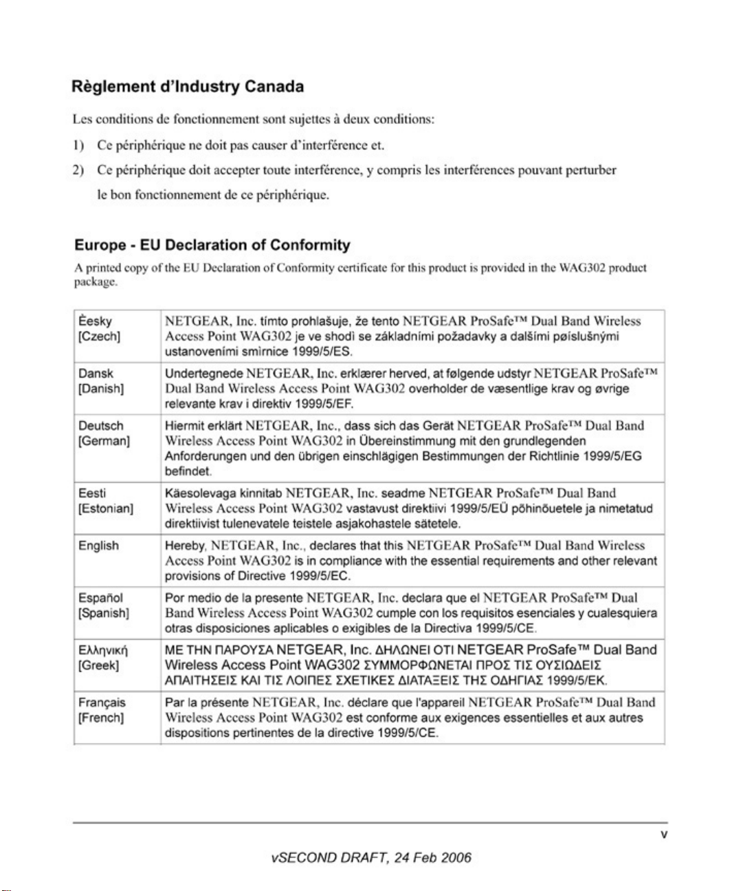
Declaration of Conformity
Operation is subject to the following two conditions: (1) this device may not cause harmful interference, and (2) this
device must accept any interference received, including interference that may cause undesired operation.
To assure continued compliance, any changes or modifications not expressly approved by the party responsible for
compliance could void the user's authority to operate this equipment. (Example - use only shielded interface cables
when connecting to computer or peripheral devices).
NOTE: This equipment has been tested and found to comply with the limits for a Class B digital device, pursuant to Part
15 of the FCC Rules. These limits are designed to provide reasonable protection against harmful interference in a
residential installation. This equipment generates, uses, and can radiate radio frequency energy and, if not installed and
used in accordance with the instructions, may cause harmful interference to radio communications.
However, there is no guarantee that interference will not occur in a particular installation. If this equipment does cause
harmful interference to radio or television reception, which can be determined by turning the equipment off and on, the
user is encouraged to try and correct the interference by one or more of the following measures:
• Reorient or locate the receiving antenna.
• Increase the separation between the equipment and receiver.
• Connect the equipment into an outlet on a circuit different from that to which the receiver is connected.
• Consult the dealer or an experienced radio/TV technician for help.
This device complies with Part 15 of the FCC Rules. Operation is subject to the following two conditions: (1) This
device may not cause harmful interference, and (2) this device must accept any interference received, including
interference that may cause undesired operation.
FCC Caution: Any changes or modifications not expressly approved by the party responsible for compliance could
void the user's authority to operate this equipment.
Placement and Range Guidelines
Indoors, computers can connect over 802.11 wireless networks at a maximum range of several hundred feet for 802.11b/
g devices. However, the operating distance or range of your wireless connection can vary significantly, based on the
physical placement of the wireless access point.
For best results, identify a location for your wireless access point according to these guidelines:
• Away from potential sources of interference, such as PCs, large metal surfaces, microwaves, and 2.4 GHz cordless
phones.
• In an elevated location such as a high shelf that is near the center of the wireless coverage area for all mobile
devices.
Failure to follow these guidelines can result in significant performance degradation or inability to wirelessly connect to
the wireless access point.
RF Exposure Warning for North America, and Australia
WARNING! To meet FCC and other national safety guidelines for RF exposure, the antennas for this device (see below)
must be installed to ensure a minimum separation distance of 20cm (7.9 in.) from persons. Further, the antennas shall not
be colocated
If this device is going to be operated in 5.15 ~ 5.25GHz frequency range, then it is restricted in indoor environment only.
We declare that the product is limited in CH1~CH11 by specified firmware controlled in the USA.
with other antenna or radio transmitter.
vSECOND DRAFT, 24 Feb 2006
iii
Page 4

Antenna Statement for North America and Australia
In addition to its own antenna, the WAG302 device has been approved for use with the following detachable antennas
and antenna cables.
Approved
Antennas
NETGEAR
ANT24D18
NETGEAR
ANT2409
NETGEAR
ANT24O5
a. WAG302 maximum radiated power in North America and Australia: 19 dBm ñ cable loss + antenna gain
Please see the product specifications at http://kbserver.netgear.com/products/WAG302.asp for an updated list
of wireless accessories approved to be used with the WAG302.
Antenna Gain and
type
14 dBi, directional
outdoor/indoor
8.5 dBi,
omnidirectional
outdoor/indoor
5 dBi, ceiling/wall
indoor
Approved Antenna
Cable
NETGEAR ACC-1031401 thru 05
NETGEAR ACC-1031401 thru 05
NETGEAR ACC-1031401 thru 05
Antenna Cable
Length
30 m 2.4 GHz
10 m 2.4 GHz
NA 2.4 GHz
ANT Frequency
Range
5 GHz
Industry Canada Compliance Statement
This Class B Digital apparatus meets all the requirements of the Canadian Interference Causing Equipment Regulations
ICES 003.
Cet appareil numerique de classe B respecte les exigences du reglement du Canada sur le materiel brouilleur NMB-003.
IC statement
Operation is subject to the following two conditions:
1) This device may not cause interference and
2) This device must accept any interference, including interference that may cause undesired operation of the device.
This device has been designed to operate with an antenna having a maximum gain of 5.39536 dBi. Antenna having a
higher gain is strictly prohibited per regulations of Industry Canada. The required antenna impedance is 50 ohms.
IMPORTANT NOTE:
IC Radiation Exposure Statement:
This equipment complies with IC radiation exposure limits set forth for an uncontrolled environment. End users must
follow the specific operating instructions for satisfying RF exposure compliance. This equipment should be installed
and operated with minimum distance 20cm between the radiator & your body.
This transmitter must not be co-located or operating in conjunction with any other antenna or transmitter.
iv
vSECOND DRAFT, 24 Feb 2006
Page 5
Page 6
Page 7

Page 8

viii
vSECOND DRAFT, 24 Feb 2006
Page 9

Contents
Reference Manual for the ProSafe™ Dual Band Wireless Access Point
WAG302
Chapter 1
About This Manual
Audience, Scope, Conventions, and Formats ................................................................1-1
How to Use This Manual ................................................................................................1-2
How to Print this Manual .................................................................................................1-2
Chapter 2
Introduction
Key Features ..................................................................................................................2-1
Compatible and Related NETGEAR Products .........................................................2-4
What’s In the Box? .........................................................................................................2-4
Hardware Description .....................................................................................................2-5
Front Panel ...............................................................................................................2-5
Rear Panel ...............................................................................................................2-6
Chapter 3
Basic Installation and Configuration
System Requirements ....................................................................................................3-1
Default Factory Settings .................................................................................................3-2
Wireless Equipment Placement and Range Guidelines .................................................3-3
Installing the WAG302 Wireless Access Point ...............................................................3-4
Logging in to the WAG302 Using Its Default IP Address ................................................3-8
Basic IP Settings ............................................................................................................3-9
Wireless Settings ..........................................................................................................3-11
Understanding WAG302 Wireless Security Options .....................................................3-13
Configuring Security Profiles ........................................................................................3-14
Profile Definition .....................................................................................................3-16
Network Authentication ..........................................................................................3-16
vSECOND DRAFT, 24 Feb 2006
ix
Page 10

Data Encryption ......................................................................................................3-17
Wireless Client Security Separation .......................................................................3-18
VLAN ID .................................................................................................................3-18
Before You Change the SSID and Wireless Security Settings ...............................3-19
Configuring the RADIUS Server Settings .....................................................................3-20
Restricting Wireless Access by MAC Address .............................................................3-21
Chapter 4
Management and Information
Changing the Administrator Password ...........................................................................4-1
Remote Management .....................................................................................................4-2
Using the Secure Telnet Interface ..................................................................................4-3
How to Use the CLI via the Console Port .................................................................4-3
CLI Commands ........................................................................................................4-4
Upgrading the Wireless Access Point Firmware ............................................................4-4
Configuration File Management .....................................................................................4-5
Backing up and Restoring the Configuration ............................................................4-5
Erasing the Configuration .........................................................................................4-6
Using the Reset Button to Restore Factory Default Settings ...................................4-6
Viewing General Information ..........................................................................................4-7
Viewing the Activity Log ..................................................................................................4-9
Viewing the Available Wireless Station List ..................................................................4-10
Viewing Statistics .......................................................................................................... 4-11
Rogue AP Detection .....................................................................................................4-13
Chapter 5
Advanced Configuration
Configuring Advanced IP Settings for Wireless Clients ..................................................5-1
Configuring Hotspot Settings ..........................................................................................5-3
Configuring Advanced Wireless Settings .......................................................................5-3
Configuring Wireless LAN Parameters ....................................................................5-4
Wi-Fi Multimedia (WMM) Setup ...............................................................................5-5
Modifying QoS Queue Parameters ..........................................................................5-5
Wireless Bridging and Repeating ...................................................................................5-6
Point-to-Point Bridge Configuration ..........................................................................5-8
Multi-Point Bridge Configuration ..............................................................................5-9
Repeater with Wireless Client Association ............................................................. 5-11
x
vSECOND DRAFT, 24 Feb 2006
Page 11

Chapter 6
Troubleshooting
No lights are lit on the access point. ...............................................................................6-1
The Wireless LAN activity light does not light up. ...........................................................6-2
The LAN light is not lit. ....................................................................................................6-2
I cannot access the Internet or the LAN with a wireless capable computer. .................6-2
I cannot connect to the WAG302 to configure it. ............................................................6-3
When I enter a URL or IP address I get a timeout error. ................................................6-3
I am unable to download files from some FTP sites. ......................................................6-4
I need to restore factory default settings. .......................................................................6-4
Appendix A
Specifications
Specifications for the WAG302 ...................................................................................... A-1
Appendix B
Command Line Reference
Accessing CLI Help ....................................................................................................... B-1
Keyboard Shortcuts and Tab Completion Help .............................................................. B-2
Interface Naming Conventions ...................................................................................... B-3
Entering CLI Commands ............................................................................................... B-5
Using the CLI to configure the WAG302 Wireless Access Point ................................... B-6
Viewing General Information ................................................................................... B-6
Configuring Basic Settings ...................................................................................... B-7
Configuring Wireless Settings ................................................................................. B-8
Configuring Security Profile Settings ....................................................................... B-9
RADIUS Server Settings ........................................................................................B-11
Access Control ...................................................................................................... B-12
Viewing and Configuring Management Settings ................................................... B-13
Viewing and Configuring System Information ....................................................... B-14
Configuring Advanced IP Settings ........................................................................ B-15
Hotspot Settings .................................................................................................... B-15
Advanced Wireless Settings ................................................................................. B-16
Advanced Access Point Settings .......................................................................... B-17
vSECOND DRAFT, 24 Feb 2006
xi
Page 12

xii
vSECOND DRAFT, 24 Feb 2006
Page 13
Chapter 1
About This Manual
This chapter describes the intended audience, scope, conventions, and formats of this manual.
Audience, Scope, Conventions, and Formats
This reference manual assumes that the reader has basic to intermediate computer and Internet
skills. However, basic computer network, Internet, firewall, and VPN technologies tutorial
information is provided on the NETGEAR Web site.
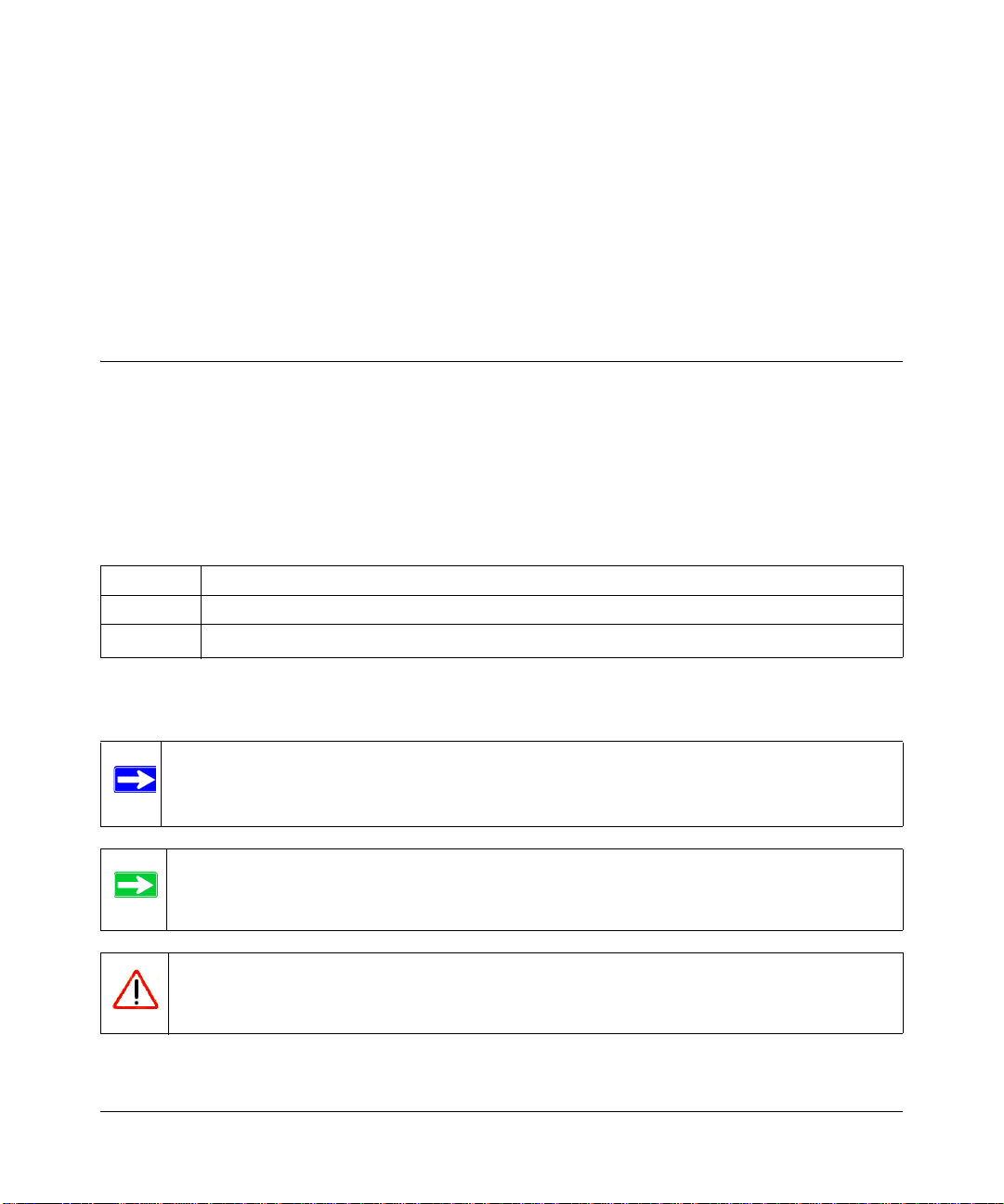
This guide uses the following typographical conventions:
Table 1-1. T ypographical Conventions
italics Emphasis, books, CDs, URL names
bold User input
fixed
Screen text, file and server names, extensions, commands, IP addresses
This guide uses the following formats to highlight special messages:
Note: This format is used to highlight information of importance or special interest.
Tip: This format is used to highlight a procedure that will save time or resources.
Warning: Ignoring this type of note may result in a malfunction or damage to the
equipment.
About This Manual 1-1
vSECOND DRAFT, 24 Feb 2006
Page 14
Reference Manual for the ProSafe™ Dual Band Wireless Access Point WAG302
This manual is written for the WAG302 Wireless Access Point according to these specifications:
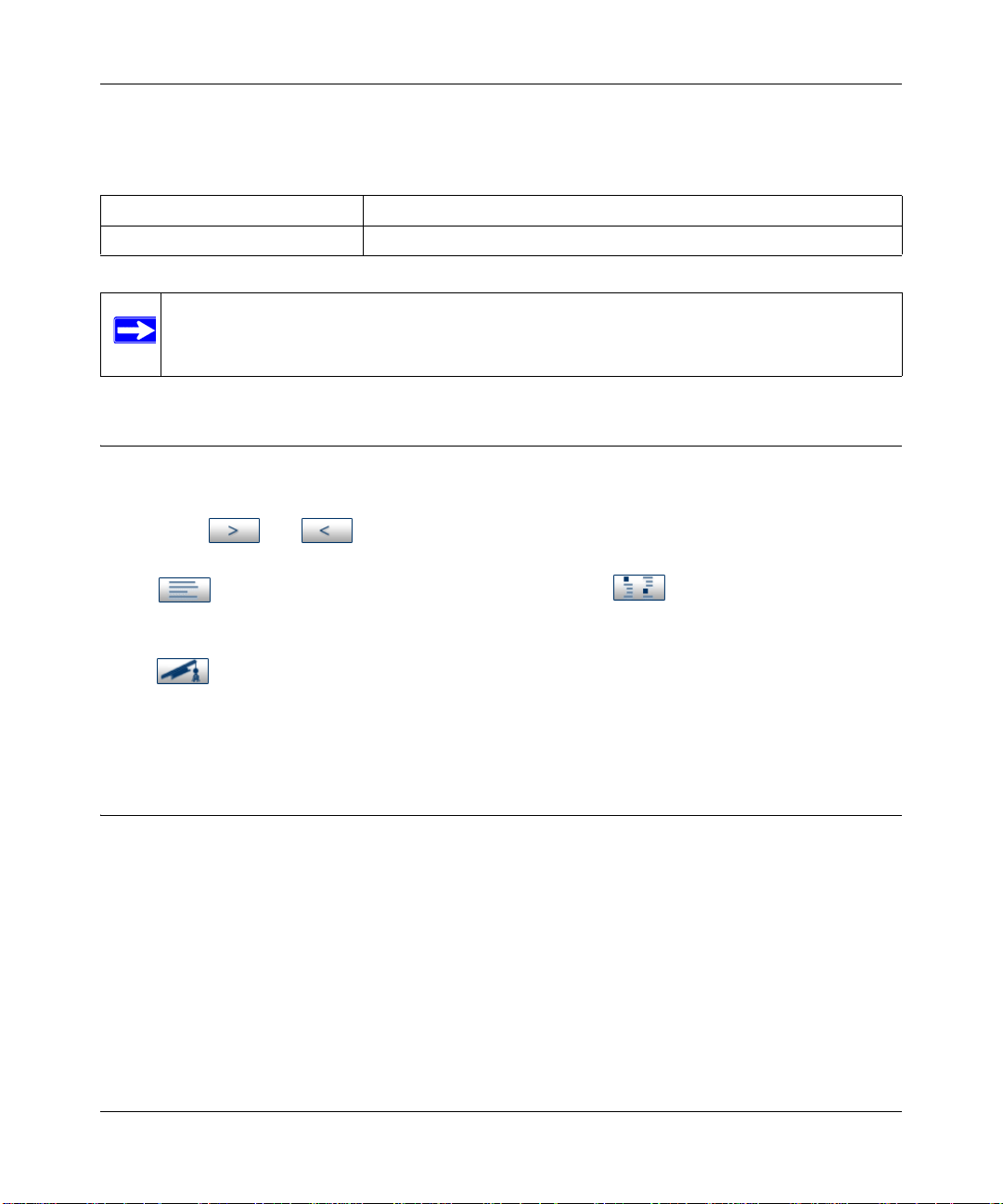
Table 1-2. Manual Scope
Product Version NETGEAR ProSafe™ Dual Band Wireless Access Point WAG302
Manual Publication Date 24 Feb 2006
Note: Product updates are available on the NETGEAR, Inc. Web site at
http://kbserver.netgear.com/products/WAG302.asp.
How to Use This Manual
The HTML version of this manual includes the following:
• Buttons, and , for browsing forwards or backwards through the manual one page
at a time
• A button that displays the table of contents and an button. Double-click on a
link in the table of contents or index to navigate directly to where the topic is described in the
manual.
• A button to access the full NETGEAR, Inc. online knowledge base for the product
model.
• Links to PDF versions of the full manual and individual chapters.
How to Print this Manual
To print this manual you can choose one of the following several options, according to your needs.
• Printing a Page in the HTML View.
Each page in the HTML version of the manual is dedicated to a major topic. Use the Print
button on the browser toolbar to print the page contents.
• Printing a Chapter.
Use the PDF of This Chapter link at the top left of any page.
1-2 About This Manual
vSECOND DRAFT, 24 Feb 2006
Page 15
Reference Manual for the ProSafe™ Dual Band Wireless Access Point WAG302
— Click the PDF of This Chapter link at the top right of any page in the chapter you want to
print. The PDF version of the chapter you were viewing opens in a browser window.
— Your computer must have the free Adobe Acrobat reader installed in order to view and
print PDF files. The Acrobat reader is available on the Adobe Web site at
http://www.adobe.com.
— Click the print icon in the upper left of the window.
Tip: If your printer supports printing two pages on a single sheet of paper, you can
save paper and printer ink by selecting this feature.
• Printing the Full Manual.
Use the Complete PDF Manua l link at the top left of any page.
— Click the Complete PDF Manual link at the top left of any page in the manual. The PDF
version of the complete manual opens in a browser window.
— Click the print icon in the upper left of the window.
Tip: If your printer supports printing two pages on a single sheet of paper, you can
save paper and printer ink by selecting this feature.
About This Manual 1-3
vSECOND DRAFT, 24 Feb 2006
Page 16

Reference Manual for the ProSafe™ Dual Band Wireless Access Point WAG302
1-4 About This Manual
vSECOND DRAFT, 24 Feb 2006
Page 17

Chapter 2
Introduction
This chapter introduces the NETGEAR ProSafe™ Dual Band Wireless Access Point WAG302.
The WAG302 is the basic building block of a wireless LAN infrastructure. It provides connectivity
between Ethernet wired networks and radio-equipped wireless notebook systems, desktop
systems, print servers, and other devices.
The wireless access point uses a network interface card (NIC) with an antenna to provide wireless
connectivity within about a 300-foot radius. The wireless access point can support 30-70 users
simultaneously.
The WAG302 acts as a bridge between the wired LAN and wireless clients. You can connect
multiple wireless access points via a wired Ethernet backbone to add more wireless network
coverage. As a wireless device moves out of the range of one access point, it moves into the range
of another. As a result, wireless clients can freely roam from one access point to another and still
maintain seamless connection to the network.
The auto-sensing capability of the WAG302 Wireless Access Point allows packet transmission at
up to 108 Mbps, or at reduced speeds to compensate for distance or electromagnetic interference.
Key Features
The WAG302 Wireless Access Point is easy-to-use and provides solid wireless and networking
support.
Supported Standards and Conventions
The following standards and conventions are supported:
• Standards Compliant. The Wireless Access Point complies with IEEE 802.11a/g standards
for Wireless LANs.
• WEP support. Includes support for 64-bit, 128-bit, and 152-bit WEP keys.
• Full WPA and WPA2 support. WPA and WPA2 enterprise-class strong security with
RADIUS and certificate authentication as well as dynamic encryption key generation.
WPA-PSK and WPA2-PSK pre-shared key authentication without the overhead of RADIUS
servers but with all of the strong security of WPA.
Introduction 2-1
vSECOND DRAFT, 24 Feb 2006
Page 18

Reference Manual for the ProSafe™ Dual Band Wireless Access Point WAG302
• Multiple BSSIDs. Support for multiple BSSIDs. When one AP is connected to a wired
network and a set of wireless stations, it is referred to as a Basic Service Set (BSS). The Basic
Service Set Identifier (BSSID) is a 32-character unique identifier attached to the header of
packets sent over a WLAN that differentiates one WLAN from another when a mobile device
tries to connect to the network.
• DHCP Client and Server Support. DHCP provides a dynamic IP address to PCs and other
devices upon request. The WAG302 can obtain network information from a DHCP server on
your network. The AP can also act as a DHCP server and provide network information for
wireless clients.
• SNMP Support. Support for Simple Network Management Protocol (SNMP) Management
Information Base (MIB) management.
Key Features
The WAG302 provides solid functionality, including these features:
• Multiple Operating Modes
– Wireless Access Point. Operates as a standard 802.11a/g.
– Point-to-Point Bridge. In this mode, the WAG302 only communicates with another
bridge-mode wireless station. You must enter the MAC address (physical address) of the
other bridge-mode wireless station in the field provided. You should use wireless security
to protect this communication.
– Point-to-Multi-Point Bridge. Select this only if this WAG302 is the “Master” for a group
of bridge-mode wireless stations. The other bridge-mode wireless stations must be set to
Point-to-Point Bridge mode, using this WAG302's MAC address. They then send all
traffic to this “Master,” rather than communicate directly with each other. You should use
wireless security to protect this traffic.
– Wireless Repeater. In this half-duplex mode, the WAG302 only communicates with
another repeater-mode wireless station. You must enter the MAC address of both adjacent
repeater-mode wireless stations in the fields provided. You should use wireless security to
protect this communication.
• Rogue Access Point Detection. For enhanced security, you can scan the wireless network to
detect rogue access points.
• Hotspot Settings. You can allow all HTTP (TCP, port 80) requests to be captured and
re-directed to the URL you specify.
• Upgradeable Firmware. Firmware is stored in a flash memory and can be upgraded easily,
using only your Web browser, and can be upgraded remotely.
2-2 Introduction
vSECOND DRAFT, 24 Feb 2006
Page 19

Reference Manual for the ProSafe™ Dual Band Wireless Access Point WAG302
• Access Control. The Access Control MAC address filtering feature can ensure that only
trusted wireless stations can use the WAG302 to gain access to your LAN.
• Security Profiles. When using multiple BSSIDs, you can configure unique security settings
(encryption, MAC filtering, etc.) for each BSSID.
• Simple Configuration. If the default settings are unsuitable, they are easy to change.
• Hidden Mode. The SSID is not broadcast, assuring only clients configured with the correct
SSID can connect.
• Configuration Backup. Configuration settings can be backed up to a file and restored.
• Secure and Economical Operation. Adjustable power output allows more secure or
economical operation.
• Power over Ethernet. Power can be supplied to the WAG302 over the Ethernet port from any
802.3af compliant mid-span or end-span source such as the NETGEAR FSM7326P Managed
Power over Ethernet Layer 3 managed switch.
• Autosensing Ethernet Connection with Auto Uplink™ Interface. Connects to 10/100
Mbps IEEE 802.3 Ethernet networks.
• LED Indicators. Power, Test, LAN speed, LAN activity, and wireless activity are easily
identified.
• Virtual APs. A single AP is segregated into multiple individual virtual APs simulating
multiple APs in a single system. This segregation allows you to enforce different security
mechanisms for different clients on the same AP.
• Wireless Virtual LAN (VLAN) Support. VLANs enable a network of computers to behave
as if they are connected to the same network even though they may actually be physically
located on different segments of a LAN. VLANs are configured through software rather than
hardware, which makes them extremely flexible. VLANs are very useful for user/host
management, bandwidth allocation and resource optimization.
• World Mode. With world mode enabled, the Access Point provides radio channel settings for
client devices that associate with the Access Point. A visitor from Europe using world mode
on a client device can associate with an Access Point in North Carolina and automatically
switch to the correct channel settings
Wireless Multimedia (WMM) Support
WMM is a subset of the 802.11e standard. WMM allows wireless traffic to have a range of
priorities, depending on the kind of data. Time-dependent information, like video or audio, has a
higher priority than normal traffic. For WMM to function correctly, Wireless clients must also
support WMM.
Introduction 2-3
vSECOND DRAFT, 24 Feb 2006
Page 20

Reference Manual for the ProSafe™ Dual Band Wireless Access Point WAG302
Compatible and Related NETGEAR Products
For a list of compatible products from other manufacturers, see the Wireless Ethernet
Compatibility Alliance Web site (WECA): http://www.wi-fi.net.
The following NETGEAR products work with the WAG302 Wireless Access Point:
• WAG511 ProSafe 108 Mbps Dual Band PC Card
• WAG311 ProSafe 108 Mbps Dual Band PCI Card
• WG311T 802.11g 108 Mbps Wireless PCI Card
• WG511T 802.11g 108 Mbps Wireless CardBus Adapter
• WG511 802.11g 54 Mbps Wireless CardBus Adapter
• WG111 801.11g 54 Mbps Wireless Bridge
What’s In the Box?
The product package should contain the following items:
• NETGEAR ProSafe™ Dual Band Wireless Access Point WAG302.
• Power adapter and cord.
• Straight through Category 5 Ethernet cable.
• Reference Manual for the ProSafe™ Dual Band Wireless Access Point WAG302.
• Resource CD for the NETGEAR ProSafe™ Dual Band Wireless Access Point WAG302.
• Support Registration card.
Contact your reseller or customer support in your area if there are any missing or damaged parts.
See the Support Information card for the telephone number of customer support in your area. You
should keep the Support Information card, along with the original packing materials, and use the
packing materials to repack the WAG302 if you need to return it for repair. To qualify for product
updates and product warranty registrations, we encourage you to register on the NETGEAR Web
site at: http://www.NETGEAR.com.
2-4 Introduction
vSECOND DRAFT, 24 Feb 2006
Page 21
Reference Manual for the ProSafe™ Dual Band Wireless Access Point WAG302
Hardware Description
This section describes the WAG302 front and rear hardware functions.
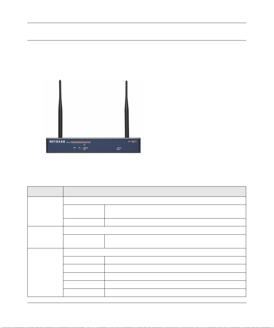
Front Panel
Figure 2-1
Viewed from left to right, the WAG302 has these status LEDs: PWR, TEST, LAN,802.11a
WLAN, and 802.11g WLAN.
LED Description
PWR Power Indicator
Off No power. If this LED does not come on with the power adapter and
cord correctly installed, see Chapter 6, “Troubleshooting.
On Power is on.
TEST Self Test Indicator
Blink Indicates self test, loading software, or system fault (if continues).
Note: This LED may blink for a minute before going off.
LAN Ethernet link indicator
Off No connection detected on the Ethernet link
Amber On 10 Mbps Ethernet link detected
Amber Blink Data is being transmitted or received on the 10 Mbps Ethernet link
Green On 100 Mbps Fast Ethernet link detected.
Green Blink Data is being transmitted or received on the 100 Mbps Ethernet link
Introduction 2-5
vSECOND DRAFT, 24 Feb 2006
Page 22
Reference Manual for the ProSafe™ Dual Band Wireless Access Point WAG302
LED Description
802.11a WLAN Wireless LAN Link Activity Indicator (5 GHz)
Off No wireless link activity.
Green Blink Wireless link activity.
802.11g WLAN Wireless LAN Link Activity Indicator (2.4 MHz)
Off No wireless link activity.
Green Blink Wireless link activity.
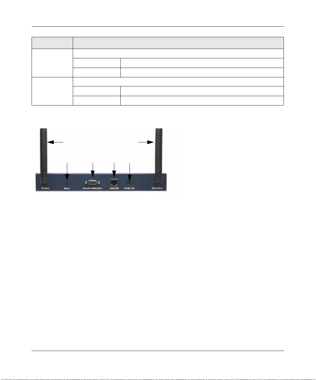
Rear Panel
1
234
Figure 2-2
1
5
Viewed from left to right, the back of the WAG302 provides the following:
1. Left and Right Detachable Antennas. The WAG302 provides two detachable antennas.
2. Reset button. This restores the default factory settings.
3. Serial Console Port. Use the male DB-9 serial port for serial DTE connections.
4. RJ-45 Ethernet LAN/POE Port. Use the WAG302 Ethernet RJ-45 port to connect to an
Ethernet LAN through a device such as a hub, switch, router, or Power Over Ethernet (POE)
switch.
5. Power socket. This connects to the WAG302 power adapter.
2-6 Introduction
vSECOND DRAFT, 24 Feb 2006
Page 23
Chapter 3
Basic Installation and Configuration
This chapter describes how to set up your NETGEAR ProSafe™ Dual Band Wireless Access Point
WAG302 for wireless connectivity to your LAN. This basic configuration enables computers with
802.11b or 802.11a/g wireless adapters to do such things as connect to the Internet or access
printers and files on your LAN.
Note: Indoors, computers can connect over 802.11a/g wireless networks at ranges of
several hundred feet or more. This distance can allow others outside your area to
access your network. It is important to take appropriate steps to secure your
network from unauthorized access. The WAG302 Wireless Access Point provides
highly effective security features which are covered in detail on the NETGEAR
Web site: http://kbserver.netgear.com/products/WAG302.asp. Deploy the security
features appropriate to your needs.
You need to prepare the following three things before you can establish a connection through your
wireless access point:
• A location for the WAG302 that conforms to the Wireless Equipment Placement and Range
Guidelines described in this chapter.
• A wired connection from the WAG302 to your LAN through a device such as a hub, switch,
router, or Cable/DSL gateway.
• One or more computers with properly configured 802.11b or 802.11a/g wireless adapters.
System Requirements
Before you install the WAG302, make sure you have the following equipment and that your
system meets these requirements:
• A 10/100 Mbps Local Area Network device such as a hub or switch.
• The Category 5 UTP straight through Ethernet cable with RJ-45 connector included in the
package, or one like it.
• A 100-240 V, 50-60 HZ AC power source.
Basic Installation and Configuration 3-1
vSECOND DRAFT, 24 Feb 2006
Page 24

Reference Manual for the ProSafe™ Dual Band Wireless Access Point WAG302
• A Web browser for configuration such as Microsoft Internet Explorer 6.0 or above, or
Netscape Navigator 4.78 or above.
• At least one computer with the TCP/IP protocol installed.
• 802.11a, 802.11g, or 802.11b-compliant devices, such as the NETGEAR WG511 Wireless
Adapter.
The WAG302 can connect to you LAN via twisted-pair Category 5 Ethernet cable with RJ-45
connectors. The LAN interface is autosensing and capable of full-duplex or half-duplex operation.
The wireless access point uses Auto Uplink™ technology. The Ethernet port automatically senses
whether the Ethernet cable plugged into the port should have a ‘normal’ connection such as to a
computer or an ‘uplink’ connection such as to a switch or hub. That port will then configure itself
correctly. This feature eliminates any concerns about crossover cables, as Auto Uplink™ will
accommodate either type of cable to make the right connection.
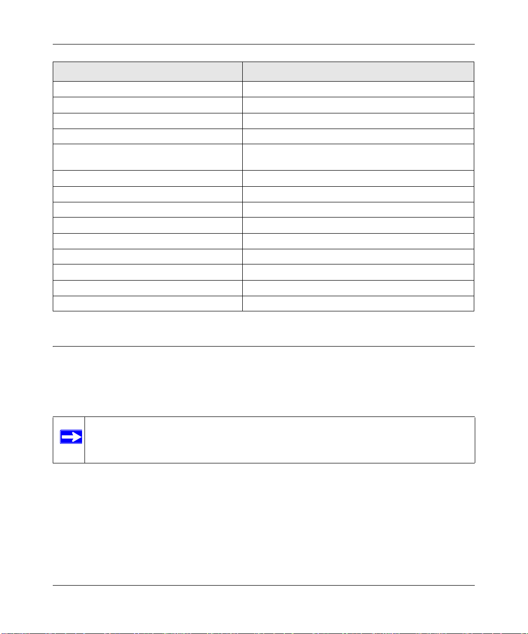
Default Factory Settings
When you first receive your WAG302, the default factory settings are set as shown in the
following table. You can restore these defaults with the Reset button on the rear panel — see
“Hardware Description” on page 2-5.
Feature Factory Default Settings
User Name (case sensitive) admin
Password (case sensitive) password
Operating Mode Access Point
Access Point Name netgearxxxxxx, where xxxxxx are the last six digits of the
wireless access point's MAC address
Built-in DHCP client DHCP client disabled; it uses the default IP address
IP Configuration IP Address: 192.168.0.230
Subnet Mask: 255.255.255.0
Gateway: 0.0.0.0
802.11a Network Name (SSID) NETGEAR_11a
802.11g Network Name (SSID) NETGEAR_11g
Broadcast Network Name (SSID) Enabled
802.11a Radio Frequency Channel Channel 52
802.11g Radio Frequency Channel Channel 11
3-2 Basic Installation and Configuration
vSECOND DRAFT, 24 Feb 2006
Page 25
Reference Manual for the ProSafe™ Dual Band Wireless Access Point WAG302
Feature Factory Default Settings
Super-G Mode Disabled
WEP/WPA Disabled
MAC Access Control Disabled
Rogue Access Point Detection Disabled
Restricting connectivity based on MAC Access
Control List
Time Zone GMT
Time Zone Adjust for Daylight Saving TIme Disabled
SNMP Disabled
Spanning Tree Protocol Enabled
VLAN (802.1Q) Enabled
DHCP Server Disabled
DHCP Server IP Address Pool 192.168.0.2 -192.168.0.50
Load Balancing Disabled
WMM Support Disabled
Disabled
Wireless Equipment Placement and Range Guidelines
The range of your wireless connection can vary significantly based on the location of the wireless
access point. The latency, data throughput performance, and notebook power consumption of
wireless adapters also vary depending on your configuration choices.
Note: Failure to follow these guidelines can result in significant performance degradation
or inability to wirelessly connect to the WAG302. For complete performance
specifications, see Appendix A, “Specifications”.
For best results, place your wireless access point:
• Near the center of the area in which your PCs operate.
• In an elevated location such as a high shelf where the wirelessly connected PCs have
line-of-sight access (even if through walls).
• Away from sources of interference, such as PCs, microwaves, and 2.4 GHz cordless phones.
Basic Installation and Configuration 3-3
vSECOND DRAFT, 24 Feb 2006
Page 26
Reference Manual for the ProSafe™ Dual Band Wireless Access Point WAG302
• Away from large metal surfaces.
Putting the antenna in a vertical position provides best side-to-side coverage. Putting the antenna
in a horizontal position provides best up-and-down coverage.
If you use multiple access points, it is better if adjacent access points use different radio frequency
Channels to reduce interference. The recommended Channel spacing between adjacent access
points is five Channels (for example, use Channels 1 and 6, or 6 and 11).
The time it takes to establish a wireless connection can vary depending on both your security
settings and placement.
Installing the WAG302 Wireless Access Point
Before you install the WAG302 Wireless Access Point, make sure that your Ethernet network is up
and working. You will be connecting the access point to the Ethernet network. Then computers
with 802.11b or 802.11a/g wireless adapters will be able to communicate with the Ethernet
network. In order for this to work correctly , verify that you h ave met all of the network and system
requirements described in “System Requirements” on page 3-1.
1. Set up the WAG302 Wireless Access Point.
Tip: Before mounting the WAG302 in a high location, first set up and test the
WAG302 to verify wireless network connectivity.
a. Prepare a computer with an Ethernet adapter. If this computer is already part of your
network, record its TCP/IP configuration settings.
b. Configure the computer with a static IP address of 192.168.0.210 and 255.255.255.0 for
the Subnet Mask.
c. Connect an Ethernet cable from the WAG302 to the computer.
d. Turn on your computer, connect the power adapter to the WAG302 and verify the
following:
– The PWR power light goes on.
– The LAN light of the wireless access point is lit when connected to a powered on
computer.
3-4 Basic Installation and Configuration
vSECOND DRAFT, 24 Feb 2006
Page 27
Reference Manual for the ProSafe™ Dual Band Wireless Access Point WAG302
2. Configure LAN and wireless access.
a. Use your Web browser to connect to the WAG302.
Enter 192.168.0.230 in the address field of your browser. The WAG302 login screen
appears. When prompted, enter admin for the user name, and password for the password,
both in lower case letters. For more information, see “Logging in to the WAG302 Using
Its Default IP Address” on page 3-8.
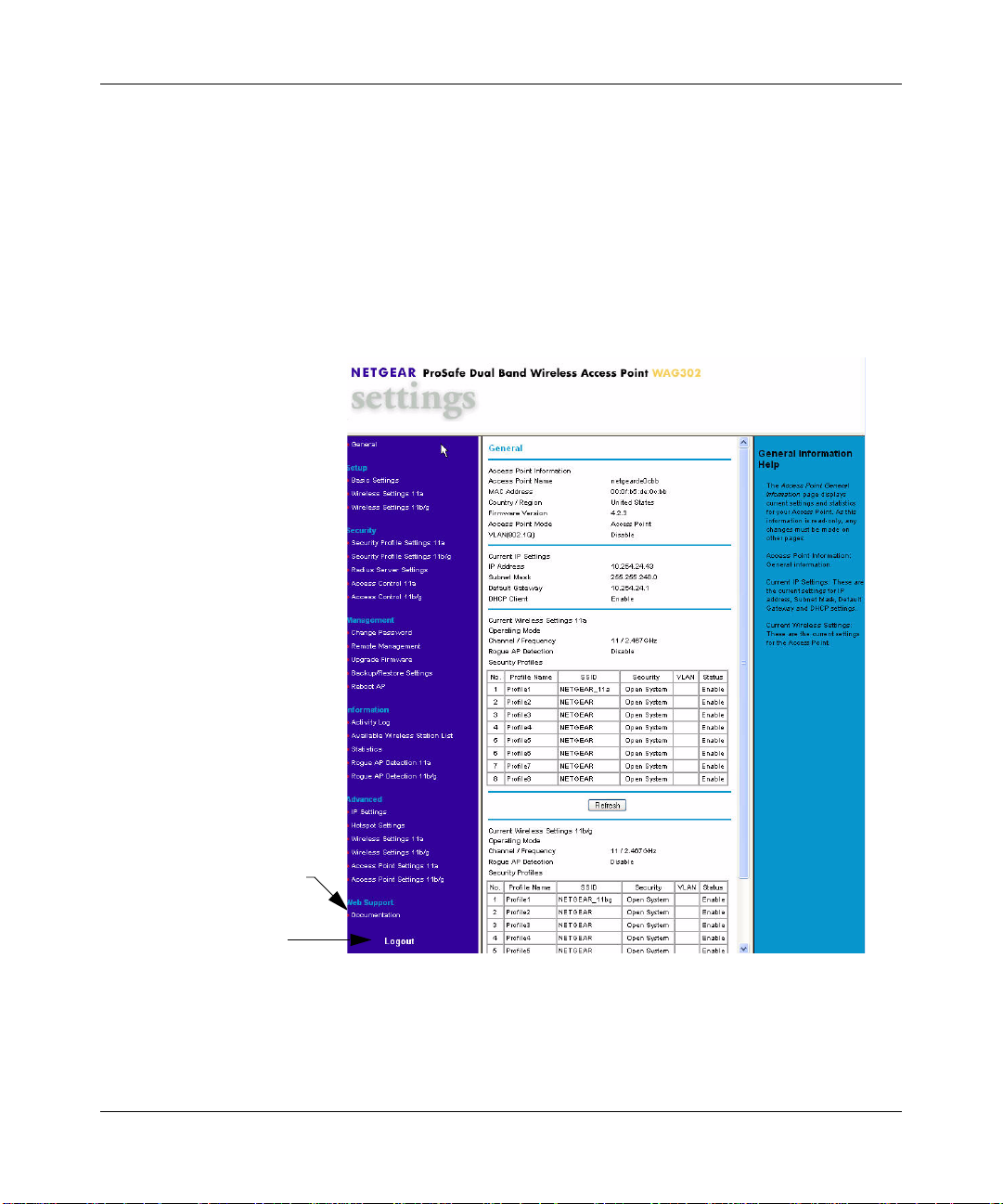
The Web br owser displays the WAG302 main menu and General page, as Figure 3-1
shows.
Click to view
documentation
Click to log out. After five
minutes with no activity,
you are logged out automatically.
Figure 3-1
For more information about the General Information fields, see “Viewing General
Information” on page 4-7.
Basic Installation and Configuration 3-5
vSECOND DRAFT, 24 Feb 2006
Page 28
Reference Manual for the ProSafe™ Dual Band Wireless Access Point WAG302
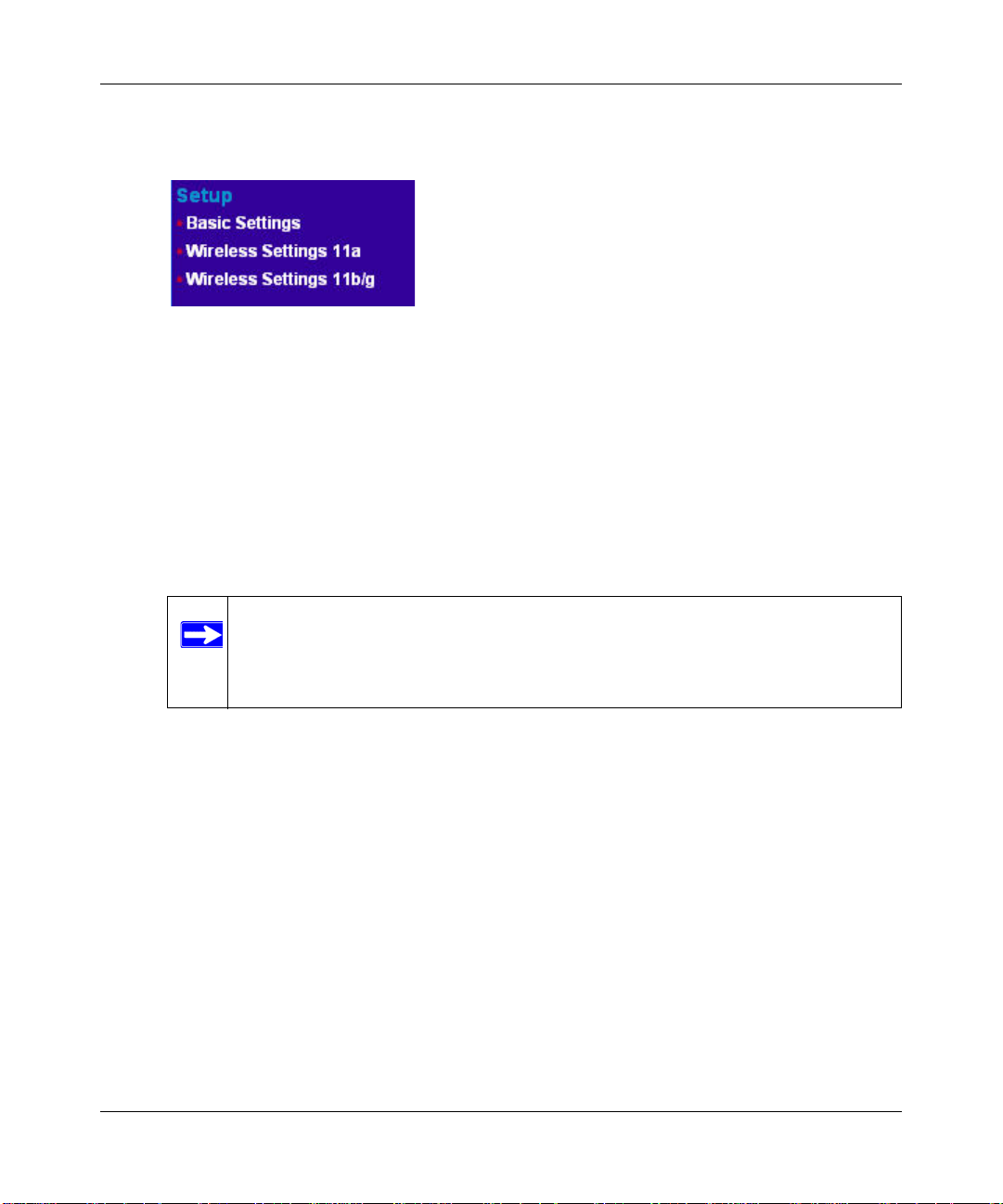
b. Click the Basic Settings link in the Setup section of the main menu to view the Basic
Settings menu.
Figure 3-2
c. Configure the settings for your network and click Apply. See the online help or “Basic IP
Settings” on page 3-9 for more information about how to configure the settings on this
page.
d. Click Wireless Settings for the 802.11a or 802.1 1b/g radio in the Setup section of the main
menu to view the Wireless Settings menu.
e. Enter the wireless settings for the 802.11a and 802.11b/g radios and click Apply. See the
online help or “Wireless Settings” on page 3-11 for information about how to configure
the settings on this page.
Note: In the USA, the Region is preset according to regulatory requirements and
cannot be changed. In other areas, you can and must set the Region. It may
not be legal to operate the wireless access point in a region other than one
of those identified in this field.
Now that you have finished the setup, you are ready to deploy the WAG302 in your network.
If needed, you can now reconfigure the computer you used for this process back to its original
TCP/IP settings.
3. Deploy the WAG302 Wireless Access Point.
a. Disconnect the WAG302 and put it where you will deploy it. The best location is elevated,
such as wall mounted, or on the top of a cubicle, at the center of your wireless coverage
area, and within line of sight of all the mobile devices. For more information, see
“Wireless Equipment Placement and Range Guidelines” on page 3-3
b. Lift the antenna on either side to be vertical.
3-6 Basic Installation and Configuration
vSECOND DRAFT, 24 Feb 2006
Page 29
Reference Manual for the ProSafe™ Dual Band Wireless Access Point WAG302
c. Connect an Ethernet cable from your WAG302 Wireless Access Point to a LAN port on
your router, switch, or hub.
Note: By default, the DHCP client on the WAG302 is disabled. If your network
uses dynamic IP addresses, you must change this setting. To connect to the
WAG302 after the DHCP server on your network assigns it a new IP
address, enter the access point name into your Web browser. The default
access point name is netgearxxxxxx, where xxxxxx represents the last 6
bytes of the MAC address. The default name is printed on the bottom label
of the WAG302.
d. Connect the power adapter to the wireless access point, and plug the power adapter in to a
power outlet. The PWR, LAN, and WLAN lights should light up.
4. Verify wireless connectivity.
Using a computer with an 802.11b or 802.11 a/g wireless adapter with the correct wireless
settings needed to connect to the WAG302 (SSID, WEP/WPA, MAC ACL, etc.), verify
connectivity by using a browser such as Mozilla Firefox, Netscape, or Internet Explorer to
browse the Internet, or check for file and printer access on your network.
Note: The default SSID is NETGEAR_11g for the 802.11b/g radio and
NETGEAR_11a for the 802.11a radio.The SSID of any wireless access
adapters must match the SSID you configure in the NETGEAR ProSafe™
Dual Band Wireless Access Point WAG302. If they do not match, you will not
get a wireless connection to the WAG302.
Note: If you are unable to connect to the WAG302 with a wireless client, see Chapter
6, “Troubleshooting
Basic Installation and Configuration 3-7
vSECOND DRAFT, 24 Feb 2006
Page 30

Reference Manual for the ProSafe™ Dual Band Wireless Access Point WAG302
Logging in to the WAG302 Using Its Default IP Address
After you install the WAG302, log in to it to configure the basic settings and the wireless settings.
The WAG302 is set, by default, with the IP address of 192.168.0.230 with DHCP disabled.
Note: The computer that you use to connect to the WAG302 should be configured with an
IP address that starts with 192.168.1.x and a Subnet Mask of 255.255.255.0.
1. Open a Web browser such as Internet Explorer, Netscape Navigator, or Mozilla Firefox.
2. Connect to the WAG302 by entering its default address of http://192.168.0.230 into your
browser.
Figure 3-3
3. A login window like the one shown below opens:
Figure 3-4
4. Log on by using the default user name of admin and default password of password.
After you log on, the Web browser displays the main menu as shown in Figure 3-1 on page
3-5.
3-8 Basic Installation and Configuration
vSECOND DRAFT, 24 Feb 2006
Page 31

Reference Manual for the ProSafe™ Dual Band Wireless Access Point WAG302
Basic IP Settings
To configure the basic settings of your wireless access point, connect to the WAG302 and click
Basic Settings in the Setup section of the WAG302 main menu. Figure 3-5 shows the Basic
Settings menu.
Figure 3-5
The Basic Settings default settings below work for most users and situations:
• Access Point Name. This unique name is the access point NetBIOS name. The default Access
Point Name is on the bottom label of the WAG302. The default name is netgearxxxxxx, where
xxxxxx represents the last six hexadecimal digits of the WAG302 MAC address. You can
change the name to a unique name up to 15 characters long.
Basic Installation and Configuration 3-9
vSECOND DRAFT, 24 Feb 2006
Page 32

Reference Manual for the ProSafe™ Dual Band Wireless Access Point WAG302
• Country/Region. This is the region where the WAG302 can be used. It may not be legal to
operate the wireless features of the wireless access point in a region other than one of those
identified in this field. For products sold in the United States, the default country domain is
preset and the channel is set to 11. For products sold outside the United States, you cannot
change the channel unless you select a country domain.
• DHCP Client: By default, Dynamic Host Configuration Protocol (DHCP) client is disabled.
After installation (“Installing the WAG302 Wireless Access Point” on page 3-4), you can
enable DHCP to let the wireless access point get its TCP/IP configuration from the DHCP
server on your network. The wireless access point gets the IP address, subnet mask and the
default gateway settings automatically from the DHCP server if DHCP is enabled.
Note: To connect to the W AG302 after the DHCP server on your network assigns
it a new IP address, enter the access point name into the address field of
your W eb browser. The default access point name is netgearxxxxxx, where
xxxxxx represents the last 6 bytes of the MAC address. The default name
is printed on the bottom label of the WAG302.
• IP Address. The default IP address is 192.168.0.230. T o change it, enter an unused IP address
from the address range used on your LAN (factory default: 192.168.0.230); or enable DHCP.
• IP Subnet Mask. Enter the subnet mask value used on your LAN (factory default:
255.255.255.0).
• Default Gateway. Enter the IP address of the gateway for your LAN. For more complex
networks, enter the address of the router for the network segment to which the wireless access
point is connected (factory default: 0.0.0.0).
• DNS Server . Enter the IP address of the Domain Name Server (DNS) you want to use (factory
default: 0.0.0.0).
• Spanning Tree Protocol. Enable or disable spanning tree protocol (factory default: enabled).
Spanning tree protocol provides network traffic optimization in settings with multiple
WAG302 Wireless Access Points.
• Enable 802.1Q VLAN. Check this box to enable the WAG302 to process VLAN membership
information.
• Untagged VLAN. Check this box and enter a VLAN ID to allow untagged frames to be
transmitted and received on the specified VLAN.
• Time Zone. Select the Time Zone to match your location. If your location uses daylight
saving, check the box Adjust for Daylight Saving Time.
3-10 Basic Installation and Configuration
vSECOND DRAFT, 24 Feb 2006
Page 33

Reference Manual for the ProSafe™ Dual Band Wireless Access Point WAG302
• The Current Time, as used on the wireless access point, is displayed.
Note: You must have an Internet connection to get the current time.
• NTP Server. Click Enable to use a network time protocol (NTP) server to synchronize the
clock in your access point, or click Disable if you do not want to use an NTP server.
• Use Custom NTP Server. If you do not want to use the default NETGEAR NTP server, click
this box and enter the hostname or IP address of the NTP server to use.
Wireless Settings
T o configure the wireless settings, connect to the WAG302 and click Wireless Settings in the Setup
section of the WAG302 main menu. The Wireless Settings menu appears, as shown in Figure 3-6.
The figure shows the 802.11b/g radio configuratio n.
Note: The configuration options for the 802.11a radio and the 802.11b/g radio are the
same, but the values are different.The 802.11a and 802.11b/g radios operate on
different channels and frequencies and have different data rates.
Figure 3-6
Basic Installation and Configuration 3-11
vSECOND DRAFT, 24 Feb 2006
Page 34

Reference Manual for the ProSafe™ Dual Band Wireless Access Point WAG302
The Wireless Settings menu options are discussed below:
• Turn Radio On. On by default, you can also turn off the radio to disable access through this
device. This can be helpful for configuration, network tuning, or troubleshooting activities.
• Wireless Network Name (SSID). The SSID is also known as the wireless network name.
Enter a value of up to 32 alphanumeric characters. In a setting where there is more than one
wireless network, different wireless network names provide a means for separating the traffic.
Any device you want to participate in a particular wireless network will need to use the SSID.
The WAG302 default SSID is NETGEAR_11g for the 802.11b/g radio and NETGEAR_11a
for the 802.11a radio. The following list contains additional information about SSIDs:
– A group of Wireless Stations and a single access point, all using the same ID (SSID), form
a Basic Service Set (BSS).
– Using the same SSID is essential. Devices with different SSIDs are unable to
communicate with each other. However, some access points allow connections from
wireless stations which have their SSID set to “any” or whose SSID is blank (null).
– A group of wireless stations and multiple access points, all using the same ID (ESSID),
form an Extended Service Set (ESS).
– Different access points within an ESS can use different channels. T o reduce interference, it
is recommended that adjacent access points should use different channels.
– As wireless stations physically move through the area covered by an ESS, they will
automatically change to the access point which has the least interference or best
performance. This capability is called roaming.
• Broadcast Wireless Network Name (SSID). The default is Yes. If you choose No then only
stations that know the SSID can connect. If you do so, then only stations that know the SSID
can connect. Disabling the SSID broadcast might interfere with the wireless network
“discovery” feature of some products.
• Wireless Mode. Select one of the following wireless operating modes for the 802.1 1 b/g radio:
– Auto (802.11g/802.11b): Both 802.11g and 802.11b wireless stations can be used. This is
the default.
– 802.11g Only: Only 802.11g wireless stations can be used.
– 802.11b Only: All 802.11b wireless stations can be used. 802.11g wireless stations can
still be used if they can operate in 802.11b mode.
The 802.11a mode is the only option available for the 802.11a radio.
3-12 Basic Installation and Configuration
vSECOND DRAFT, 24 Feb 2006
Page 35

Reference Manual for the ProSafe™ Dual Band Wireless Access Point WAG302
• Channel/Frequency. This field sets the operating frequency to use. You should not need to
change the channel unless you notice interference problems, or if you are setting up the
WAG302 near another access point. The wireless channel range for the 802.11b/g radio is 1 to
11 for USA and Canada and 1 to 13 for Europe and Australia. The default is channel 1 1. There
are 13 channels available for the 802.11a radio. The default is channel 52.
– Access points use a fixed channel. You can select the channel to provide the least
interference and best performance. In the USA and Canada, 11 channels are available on
the 802.11b/g radio.
– If you use multiple access points, it is better if adjacent access points use different
channels to reduce interference. The recommended channel spacing between adjacent
access points is five channels for the 802.11b/g radio (for example, use channels 1 and 6,
or 6 and 11) and eight channels for the 802.11a radio (for example, use channels 36 and 44
or channels 44 and 52).
– In “Infrastructure” mode, wireless stations normally scan all channels, looking for an
access point. If more than one access point can be used, the one with the strongest signal is
used. This can only happen when the access points use the same SSID.
See http://documentation.netgear.com/reference/enu/wireless/index.htm for more information
about wireless channels.
• Data Rate. Shows the available transmit data rate of the wireless network. The default is Best.
• Output Power. Set the transmit signal strength of the access point (AP). The options are Full,
Half, Quarter, Eighth, and Min. Decrease the transmit power if two or more APs are close
together and use the same channel frequency. The default is Full.
Understanding WAG302 Wireless Security Options
Your wireless data transmissions can be received well beyond your walls by anyone with a
compatible adapter. For this reason, use the security features of your wireless equipment. The
WAG302 Wireless Access Point provides highly effective security features which are covered in
detail in this chapter. Deploy the security features appropriate to your needs.
There are several ways you can enhance the security of your wireless network:
• Restrict Access Based on MAC address. You can restrict access to only trusted PCs so that
unknown PCs cannot wirelessly connect to the WAG302. MAC address filtering adds an
obstacle against unwanted access to your network, but the data broadcast over the wireless link
is fully exposed.
Basic Installation and Configuration 3-13
vSECOND DRAFT, 24 Feb 2006
Page 36

Reference Manual for the ProSafe™ Dual Band Wireless Access Point WAG302
• Turn Off the Broadcast of the Wireless Network Name (SSID). If you disable broadcast of
the SSID, only devices that have the correct SSID can connect. This nullifies the wireless
network ‘discovery’ feature of some products such as Windows XP, but the data is still fully
exposed to a determined person using specialized test equipment like wireless sniffers.
• Use WEP. Wired Equivalent Privacy (WEP) data encryption provides data security. WEP
Shared Key authentication and WEP data encryption will block all but the most determined
eavesdropper.
• Use IEEE 802.1x. IEEE 802.1x is the standard for passing the Extensible Authentication
Protocol (EAP) over an 802.11 wireless network using a protocol called EAP Encapsulation
Over LANs (EAPOL). This is a newer, more secure standard than Static WEP.
• Use WPA, WPA-PSK, WPA2, or WPA2-PSK. Wi-Fi Protected Access (WPA and WPA2)
data encryption provides data security . The very strong authentication along with dyn amic per
frame rekeying of WPA make it virtually impossible to compromise. Because this is a newer
standard than the other security options, wireless device driver and software availability may
be limited.
Configuring Security Profiles
You can configure up to eight unique security settings for each radio (802.11a and 802.11b/g) on
the WAG302. Figure 3-7 shows the Security Profile Settings page. The options and procedures to
configure security profiles on the 802.11a and 802.11b/g radios are the same.
Use the following steps to configure a Security Profile.
1. Connect to the WAG302.
In the address field of your Web browser, enter the default LAN address of
http://192.168.0.230. Log in with the user name of admin and default password of password,
or log in by using the LAN address and password that you configured.
2. In the Security menu, click Security Profile Settings.
Note: If you are using RADIUS Server Settings, set them up first, as described in
“Configuring the RADIUS Server Settings” on page 3-20.
The main Security Profile Settings page appears and displays the current settings for the eight
Security Profiles. By default, all Security Profiles are enabled and have no security. To disable
a Security Profile, click the Enable check box to clear the check, and then click Apply.
3-14 Basic Installation and Configuration
vSECOND DRAFT, 24 Feb 2006
Page 37

Reference Manual for the ProSafe™ Dual Band Wireless Access Point WAG302
3. Select the Security Profile to configure and click Edit.
The Security Profile Configuration page appears, as shown below.
Selected
Security Profile
Figure 3-7
4. Enter the settings for the Security Profile, which are described on the following page.
5. To update the settings, click Apply.
Note: If you use a wireless computer to configure Security Profile settings, and if
your computer uses the Security Profile that you change, you will be
disconnected when you click Apply. Reconfigure your wireless adapter to
match the new settings or access the wireless access point from a wired
computer to make any further changes.
Basic Installation and Configuration 3-15
vSECOND DRAFT, 24 Feb 2006
Page 38

Reference Manual for the ProSafe™ Dual Band Wireless Access Point WAG302
Profile Definition
The following settings are in the Profile Definition section on the Security Profile Configuration
screen:
• Security Profile Name. Use a name that makes it easy to recognize the profile, and to tell
profiles apart.
• Wireless Network Name (SSID). The SSID is also known as the wireless network name. The
SSID separates network traffic from different wireless networks. For more information about
the SSID, see Wireless Network Name (SSID) on page 3-12.
• Broadcast Wireless Network Name (SSID). This field lets you turn off the SSID broadcast.
If you do so, then only stations that know the SSID can connect. Disabling the SSID broadcast
might interfere with the wireless network “discovery” feature of some products. The default is
to enable SSID broadcast.
Network Authentication
The WAG302 Wireless Access Point is set by default as an open system with no authentication.
When setting up Network Authentication, note the following information:
• If you are using Access Point mode, then all options are available. In other modes such as
Repeater or Bridge, some options might be unavailable.
• Not all wireless adapters support WPA or WPA2. Windows XP and Windows 2000 with
Service Pack 3 do include the client software that supports WPA. However, client software is
required on the client. Consult the product documentation for your wireless adapter and WPA
or WPA2 client software for instructions about configuring WPA2 settings.
You can configure the WAG302 to use the types of network authentication shown in the table
below.
Network Authentication Types
Open System Can be used with WEP encryption or no encryption.
Shared Key You must use WEP encryption and enter at least one shared key.
Legacy 802.1x You must configure the RADIUS Server Settings to use this option.
WPA-PSK You must use TKIP encryption and enter the WPA passphrase
(Network key).
WPA with RADIUS You must configure the RADIUS Server Settings to use this option.
3-16 Basic Installation and Configuration
vSECOND DRAFT, 24 Feb 2006
Page 39

Reference Manual for the ProSafe™ Dual Band Wireless Access Point WAG302
Network Authentication Types
WPA2-PSK WPA2 is a later version of WPA. Only select this if all clients support
WPA2. If selected, you must use AES encryption and enter the WPA
passphrase (Network key).
WPA-PSK and
WPA2-PSK
WPA2 with RADIUS WPA2 is a later version of WPA. Only select this if all clients support
WPA and WPA2 with
RADIUS
This selection allows clients to use either WPA (with TKIP) or WPA2
(with AES). If selected, you must use TKIP + AES encryption and enter
the WPA passphrase (Network key).
WPA2. If selected, you must use AES encryption and configure the
RADIUS Server Settings.
This selection allows clients to use either WPA (with TKIP) or WPA2
(with AES). If selected, you must use TKIP + AES encryption and
configure the RADIUS Server Settings.
Data Encryption
Select the data encryption that you want to use. The available options depend on the Network
Authentication setting above (otherwise, the default is None). The Data Encryption settings are
explained in the table below:
Data Encryption Settings
None No encryption is used.
64 bits WEP Standard WEP encryption, using 40/64 bit encryption.
128 bits WEP Standard WEP encryption, using 104/128 bit encryption.
152 bits WEP Proprietary mode that will only work with other wireless devices that
support this mode.
TKIP This is the standard encryption method used with WPA.
AES This is the standard encryption method for WPA2. Some clients may
support AES with WPA, but this is not supported by this Access Point.
TKIP + AES This setting supports both WPA and WPA2. Broadcast packets use
TKIP. For unicast (point-to-point) transmissions, WPA clients use TKIP,
and WPA2 clients use AES.
The Passphrases and Keys are explained below:
• Passphrase. T o use the Passphrase to generate the WEP keys, enter a passphrase and click the
Generate Keys button. You can also enter the keys directly. These keys must match the other
wireless stations.
Basic Installation and Configuration 3-17
vSECOND DRAFT, 24 Feb 2006
Page 40

Reference Manual for the ProSafe™ Dual Band Wireless Access Point WAG302
• Key 1, Key 2, Key 3, Key 4. If using WEP, select the key to be used as the default key. Data
transmissions are always encrypted using the default key. The other keys can only be used to
decrypt received data.
• WPA Pre-Shared Key. If using WPA-PSK, enter the passphrase here. All wireless stations
must use the same passphrase (network key). The network key must be from 8 to 63 characters
in length.
Wireless Client Security Separation
If enabled, the associated wireless clients will not be able to communicate with each other. This
feature is used for hotspots and other public access situations. The default is disabled.
VLAN ID
Enter a VLAN ID from 1-4094 to assign traffic from wireless clients to a VLAN. When a wireless
client uses this Security Profile, the traffic is tagged with the VLAN ID you specify. To assign
multiple Security Profiles to the same VLAN, enter the same VLAN ID for each profile. The
default VLAN ID is 1. If you enter a VLAN ID that is not the default, make sure the VLAN ID
matches the VLAN ID that switches and other network devices use on the LAN.
3-18 Basic Installation and Configuration
vSECOND DRAFT, 24 Feb 2006
Page 41

Reference Manual for the ProSafe™ Dual Band Wireless Access Point WAG302
Before You Change the SSID and Wireless Security Settings
For a new wireless network, print or copy this form and fill in the settings. For an existing wireless
network, the person who set up or is responsible for the network can provide this information. Be
sure to set the Regulatory Domain correctly as the first step. Store this information in a safe place.
• SSID: The Service Set Identification (SSID) identifies the wireless local area network. You
may customize it by using up to 32 alphanumeric characters. Write your SSID on the line.
SSID: _________________________ __________
Note: The SSID in the wireless access point is the SSID you configure in the wireless adapter
card. All wireless nodes in the same network must be configured with the same SSID.
• Authentication
Circle one: Open System or Shared Key. Choose “Shared Key” for more security.
Note: If you select shared key, the other devices in the network will not connect unless they
are set to Shared Key and have the same keys in the same positions as those in the WAG302.
• WEP Encryption Keys
For all four data encryption keys, choose the Key Size. Circle one: 64, 128, or 152 bits
Key 1: ___________________________________
Key 2: ___________________________________
Key 3: ___________________________________
Key 4: ___________________________________
• WPA-PSK (Pre-Shared Key)WPA2-PSK (Pre-Shared Key)
Record the WPA-PSK key:Record the WPA2-PSK key:
Key: ________________________________
Key: _______________________________
• WPA RADIUS Settings
For WPA, record the following settings for the primary and secondary RADIUS servers:
Server Name/IP Address: Primary _________________
Port: ___________________________________
Secondary __________________
Shared Secret: ___________________________________
• WPA2 RADIUS Settings
For WPA2, record the following settings for the primary and secondary RADIUS servers:
Server Name/IP Address: Primary _________________
Port: ___________________________________
Secondary __________________
Shared Secret: ___________________________________
Basic Installation and Configuration 3-19
vSECOND DRAFT, 24 Feb 2006
Page 42

Reference Manual for the ProSafe™ Dual Band Wireless Access Point WAG302
Configuring the RADIUS Server Settings
Use the following steps to view or change the RADIUS Server Settings.
1. Connect to the WAG302.
In the address field of your Web browser,
enter the default LAN address of
http://192.168.0.230. Log in with the user
name of admin and default password of
password, or log in by using the LAN address
and password that you configured.
2. In the Security menu, click RADIUS Server
Settings.
3. Enter the settings, and click Apply.
Figure 3-8
The following list describes the RADIUS Server Settings:
• Authentication/Access Control RADIUS Server Configuration. This configuration is
required for authentication and access control using a RADIUS Server.The IP Address, Port
Number and Shared Secret are required for communication with the RADIUS Server. You can
configure a Secondary RADIUS Server to use if the Primary RADIUS Server fails.
• IP Address. The IP address of the RADIUS Server. The default is 0.0.0.0.
• Port Number. The port number of the RADIUS Server. The default is 1812.
• Shared Secret. This is shared between the Wireless Access Point and the RADIUS Server
while authenticating the supplicant (wireless client).
• Accounting RADIUS Server Configuration. This configuration is required for accounting
using a RADIUS Server. The IP Address, Port Number and Shared Secret are required for
communication with the RADIUS Server. You can configure a Secondary RADIUS Server to
use if the Primary RADIUS Server fails.
3-20 Basic Installation and Configuration
vSECOND DRAFT, 24 Feb 2006
Page 43

Reference Manual for the ProSafe™ Dual Band Wireless Access Point WAG302
• IP Address. The IP address of the RADIUS Server. The default is 0.0.0.0.
• Port Number. Port number of the RADIUS Server. The default is 1813.
• Shared Secret. This is shared between the Wireless Access Point and the RADIUS Server
while authenticating the supplicant.
Restricting Wireless Access by MAC Address
To restrict access based on MAC addresses, use the following steps:
1. Connect to the WAG302.
In the address field of your Web browser, enter the default LAN address of
http://192.168.0.230. Log in with the user name of admin and default password of password,
or log in by using the LAN address and password that you configured.
2. From the Security menu, click the Access Control link to display the Access Control menu
shown in Figure 3-9.
Figure 3-9
Basic Installation and Configuration 3-21
vSECOND DRAFT, 24 Feb 2006
Page 44

Reference Manual for the ProSafe™ Dual Band Wireless Access Point WAG302
3. Select the Turn Access Control On check box.
Note: When configuring t he WAG302 from a wireless computer whose MAC address
is not in the access control list, if you select Turn Access Control On, you will
lose your wireless connection when you click Apply . You must then access the
wireless access point from a wired computer or from a wireless computer
which is on the access control list to make any further changes.
4. Choose to use the local MAC address database stored on the access point, or use the RADIUS
MAC address database stored on a RADIUS server.
• If you choose the RADIUS MAC Address Database, you must configure the RADIUS
Server Settings first.
• If you choose Local MAC Address Database, either select from the list of available
wireless cards the WAG302 has found in your area, or enter the MAC address and device
name for a device you plan to use.
You can usually find the MAC address printed on the wireless adapter. Click Add to add
the wireless device to the access list. Repeat these steps for each additional device you
want to add to the list.
5. Be sure to click Apply to save your wireless access control list settings.
Now, only devices on the MAC ACL will be allowed to wirelessly connect to the WAG302.
3-22 Basic Installation and Configuration
vSECOND DRAFT, 24 Feb 2006
Page 45

Chapter 4
Management and Information
This chapter describes how to use the management and information features of your NETGEAR
ProSafe™ Dual Band Wireless Access Point WAG302. To get to these features, connect to the
WAG302 as described in “Logging in to the WAG302 Using Its Default IP Address” on page 3-8.
Changing the Administrator Password
The default password is password. NETGEAR recommends that you change this password to a
more secure password. You cannot change the administrator login name.
From the WAG302 main menu,
click Change Password to go to
the menu shown below.
To change the password, first
enter the old password, and
then enter the new password
twice. Click Apply to save your
change.
Figure 4-1
Management and Information 4-1
vSECOND DRAFT, 24 Feb 2006
Page 46

Reference Manual for the ProSafe™ Dual Band Wireless Access Point WAG302
Remote Management
To access the Remote Management screen, enter the LAN address of the WAG302 into the
address field of your browser . After you log in, click Remote Management under Management
on the main menu.
Figure 4-2
Enter the Remote Management information.
• Remote Console, Secure Shell (SSH): If set to Enable, the Wireless Access Point will only
allow remote access via Secure Shell and Secure Telnet. The default is Enable.
• SNMP: Enable SNMP to allow the SNMP network management software, such as HP
OpenView, to manage the wireless access point via SNMPv1/v2 protocol.
• Public Community Name: The community string to allow the SNMP manager to read the
wireless access point's MIB objects. The default is public.
• Private Community Name: The community string to allow the SNMP manager to read and
write the wireless access point's MIB objects. The default is private.
• IP address to Receive T raps: The IP address of the SNMP manager to receive traps sent from
the wireless access point. The default is 0.0.0.0.
4-2 Management and Information
vSECOND DRAFT, 24 Feb 2006
Page 47

Reference Manual for the ProSafe™ Dual Band Wireless Access Point WAG302
Using the Secure Telnet Interface
The WAG302 includes a secure Telnet command line interface (CLI). You can access the CLI
from a secure Telnet client over the Ethernet port or over the serial console port.
Note: You must use a secure Telnet client such as PuTTY. Also, when you configure the
client, use the SSH1, 3DES option. If you use the Telnet client to connect over the
Ethernet port, use the IP address of the WAG302 as the host name.
How to Use the CLI via the Console Port
1. Using a null-modem cable, connect a VT100/ANSI terminal or a workstation to the port
labeled Console.
If you attached a PC, Apple Macintosh, or UNIX workstation, start a secure
terminal-emulation program.
2. Configure the terminal-emulation program to use the following settings:
• Baud rate: 9600 bps
• Data bits: 8
• Parity: none
•Stop bit: 1
• Flow control: none
These settings appear below the connector on the back panel.
3. Press ENTER, and a screen similar to the one in Figure 4-3 should appear.
Figure 4-3
The login name is admin and password is the default password.
Management and Information 4-3
vSECOND DRAFT, 24 Feb 2006
Page 48

Reference Manual for the ProSafe™ Dual Band Wireless Access Point WAG302
After a successful login, the screen should show the (Access Point Name)> prompt. In this
example, the prompt is NETGEAR-WAG302>.
Press TAB two times (TAB + TAB) to display the CLI command help.
CLI Commands
The CLI commands that correspond to the W eb interface are explained in Appendix B, “Command
Line Reference”.
Upgrading the Wireless Access Point Firmware
Warning: When uploading firmware to the WAG302 Wireless Access Point, do not
interrupt the W eb browser by closing the window, clicking a link, or loading a
new page. If the browser is interrupted, the upload may fail, corrupt the
firmware, and render the WAG302 completely inoperable.
You cannot upgrade the firmware from a computer that is connected to the WAG302 with a
wireless link. You must use a computer that is connected to the WAG302 with an Ethernet cable.
The WAG302 Wireless Access Point firmware is stored in FLASH memory and can be upgraded
as new firmware is released by NETGEAR. You can download the upgrade files from the
NETGEAR W eb site. If the upgrade file is compressed (.ZIP file), you must first extract the image
(.IMG) file before you send it to the wireless access point. The upgrade file can be sent using your
browser.
Note: The Web browser used to upload new firmwa re into the WAG302 must support
HTTP uploads, such as Microsoft Internet Explorer 6.0 or above, or Netscape
Navigator 4.78 or above.
Use the following steps to upgrade the firmware:
1. Download the file from NETGEAR, save it to your hard disk, and unzip it.
2. If you want to save your configuration settings, see “Backing up and Restoring the
Configuration” on page 4-5.
3. From the main menu Management section, click the Upgrade Firmware link.
4. In the Upgrade Firmware menu, click the Browse button and browse to the location of the
image (.IMG) upgrade file.
4-4 Management and Information
vSECOND DRAFT, 24 Feb 2006
Page 49

Reference Manual for the ProSafe™ Dual Band Wireless Access Point WAG302
5. Click Upload.
When the upload completes, your wireless access point automatically restarts. The upgrade
process typically takes about one minute.
In some cases, you may need to reconfigure the wireless access point after upgrading.
Configuration File Management
The WAG302 Wireless Access Point settings are stored in the wireless access point in a
configuration file. This file can be saved (backed up) to a computer, retrieved (restored) from a
computer, or cleared to factory default settings.
Click Backup/Restore Settings under the Management heading to go to the menu shown in
Figure 4-4.
Figure 4-4
The following sections describes the options available on the Backup/Restore Settings page.
Backing up and Restoring the Configuration
T o save your settings, click Backup. Your browser extracts the configuration file from the wireless
access point and prompts you for a location on your computer to store the file. You can give the
file a meaningful name at this time, such as WAG302.cfg.
Management and Information 4-5
vSECOND DRAFT, 24 Feb 2006
Page 50

Reference Manual for the ProSafe™ Dual Band Wireless Access Point WAG302
To restore your settings from a saved configuration file, enter the full path to the file on your
computer or click the Browse button to locate the file. When you have located it, click the Restore
button to upload the file. After completing the upload, the WAG302 reboots automatically.
Erasing the Configuration
You can erase the wireless access point configurations and return to the factory default settings.
After you erase the configurations, the wireless access point’s password will be password, the
SSID will be NETGEAR, the DHCP client will be disabled, the default LAN IP address will be
192.168.0.230, and the access point name is reset to the name printed on the label on the bottom of
the unit.
Using the Reset Button to Restore Factory Default Settings
If you do not know the login password or IP address, you can still restore the factory default
configuration settings with the Reset button. This button is on the rear panel of the wireless access
point (see “Rear Panel” on page 2-6).
The reset button has two functions:
• Reboot. When pressed and released, the Wireless Access Point reboots (restart).
• Reset to Factory Defaults. When pressed and held down, it clears all data and restores all
settings to the factory default values.
To clear all data and restore the factory default values:
1. Hold the Reset Button until the LEDs blink twice, usually more than five seconds.
2. Release the Reset Button.
The factory default configuration has now been restored, and the WAG302 is ready for use.
4-6 Management and Information
vSECOND DRAFT, 24 Feb 2006
Page 51

Reference Manual for the ProSafe™ Dual Band Wireless Access Point WAG302
Viewing General Information
The information on the General screen is a summary of the WAG302 configuration settings. From
the WAG302 main menu, click General to view the screen shown below.
Figure 4-5
Table 4-1. General Information Fields
Field Description
Access Point Information
Access Point Name
(NetBIOS name)
Management and Information 4-7
The name of the access point, which you can configure.
vSECOND DRAFT, 24 Feb 2006
Page 52

Reference Manual for the ProSafe™ Dual Band Wireless Access Point WAG302
Table 4-1. General Information Fields
Field Description
Country/Region The domain or region for which the wireless access point is licensed for
use. It may not be legal to operate this wireless access point in a region
other than one of those identified in this field.
Firmware Version The version of the firmware currently installed.
Access Point Mode The operating mode of the WAG302: Access Point, Point-to-point
bridge, Multi-point bridge or Repeater.
VLAN (802.1Q) Indicates if VLAN support is enabled. The default is enabled.
Management VLAN ID Displays the VLAN ID.
Current IP Settings
IP Address The IP address of the wireless access point.
Subnet Mask The subnet mask for the wireless access point.
Default Gateway The default gateway for the wireless access point communication.
DHCP Client If the DHCP Client is enabled, the current IP address was obtained
from a DHCP server on your network. Disabled indicates a static IP
configuration.
MAC Address The Media Access Control address (MAC address) of the wireless
access point’s Ethernet port.
Current Wireless Settings
Channel/Frequency The channel the wireless port uses. The default channel setting is 11.
For the frequencies used on each channel, see
http://documentation.netgear.com/reference/enu/wireless/index.htm.
Security Profiles For each Security Profile, the following information is displayed: Profile
Name, SSID, Security, VLAN, and Status.
4-8 Management and Information
vSECOND DRAFT, 24 Feb 2006
Page 53

Reference Manual for the ProSafe™ Dual Band Wireless Access Point WAG302
Viewing the Activity Log
To access the Activity Log, connect to the WAG302 and click Activity Lo g u nder th e Info rmation
heading.
Figure 4-6
You can use a SysLog server to view the Activity Log. If you have a SysLog server on your LAN,
then enable SysLog. If enabled, you must enter the IP address of your SysLog server and the port
number that your SysLog server uses.
• SysLog Server IP Address: The access point sends all the SysLog messages to the specified
IP address if SysLog option is enabled. Default: 0.0.0.0
• Port: The port number configured in the SysLog server on your LAN. The default is 514.
The Activity Log Window displays the Access Point system activity.
You can click Refresh to update the display. To save the log contents into a file on your PC, click
Save As and save the file to a disk drive.
Management and Information 4-9
vSECOND DRAFT, 24 Feb 2006
Page 54

Reference Manual for the ProSafe™ Dual Band Wireless Access Point WAG302
Viewing the Available Wireless Station List
The Available Wi reless Station List contains a table of all IP devices associated with the wireless
access point for the Wired Network Name (SSID).
From the WAG302 main menu, under the Information heading,
click Available Wireless Station List to view the list.
For each device, the Available Wireless Station List table shows
the Station ID, MAC address, IP Address, and Status (whether
the device is allowed to communicate with the wireless access
point or not).
Figure 4-7
If the wireless access point is rebooted, the table data is lost until the wireless access point
rediscovers the devices. To force the wireless access point to look for associated devices, click the
Refresh button.
Note: A wireless network can include multiple wireless access points that use the same
network name (SSID). This extends the reach of the wireless network. Users can
roam from one access point to another, providing seamless network connectivity. If
this is the case, only the stations associated with this access point are shown in the
Available Station List.
4-10 Management and Information
vSECOND DRAFT, 24 Feb 2006
Page 55

Reference Manual for the ProSafe™ Dual Band Wireless Access Point WAG302
Viewing Statistics
The Statistics screen provides LAN and WLAN statistics. From the WAG302 main menu, click
Statistics under the Information heading to view the screen shown in Figure 4-8.
Figure 4-8
Table 4-2 explains the fields on the Statistics page.
Table 4-2. Access Point Statistics
Field Description
Wired Ethernet Received/Transmitted
Packets The number of packets sent since the WAG302 was restarted.
Bytes The number of bytes sent since the WAG302 was restarted.
Management and Information 4-11
vSECOND DRAFT, 24 Feb 2006
Page 56

Reference Manual for the ProSafe™ Dual Band Wireless Access Point WAG302
Table 4-2. Access Point Statistics
Field Description
For Each Wireless Security
Profile
Unicast Packets The Unicast packets sent since the WAG302 was restarted.
Broadcast Packets The Broadcast packets sent since the WAG302 was restarted.
Multicast Packets The Multicast packets sent since the WAG302 was restarted.
Total Packets The Wireless packets sent since the WAG302 was restarted.
Total Bytes The Wireless bytes sent since the WAG302 was restarted.
Refresh button Click the Refresh button to update the statistics on this screen.
Received/Transmitted
4-12 Management and Information
vSECOND DRAFT, 24 Feb 2006
Page 57

Reference Manual for the ProSafe™ Dual Band Wireless Access Point WAG302
Rogue AP Detection
The WAG302 can detect rogue APs and wireless stations and exclude them from connecting to the
WAG302 Wireless Access Point.
From the WAG302 main menu,
click Rogue AP Detection to
view this menu.
• If you enable Rogue AP
Detection, the AP
continuously scans the
wireless network and
collects information about
all APs heard on its
channel.
• You can click Rescan to
discover the APs.
• Click Grant to add any AP
to the Known AP List.
Click Delete to remove an
AP from the list.
• To export the list of known
APs to a file, click Save. A
window opens so you can
browse to the location
where you want to save the
file. The default file name
is WAG302Rogue.cfg
Figure 4-9
Management and Information 4-13
vSECOND DRAFT, 24 Feb 2006
Page 58

Reference Manual for the ProSafe™ Dual Band Wireless Access Point WAG302
To import a list of known APs, use the following steps:
1. Create a text file that contains the MAC address of each known AP, separated by a space.
The following example shows a list of six known APs that an administrator might upload to
the AP:
00:0c:41:d7:ee:a5 00:0f:b5:92:cd:49 00:12:17:70:85:3d
00:14:bf:ae:b1:e4 00:40:f4:f8:47:03 00:0c:41:d7:ee:b4
2. Select Replace to replace the existing list of known APs, or select Merge to add the new MAC
addresses to the existing list.
3. Click Browse and navigate to the location where you saved the text file.
4. Select the file and click Open.
5. Click Import to upload the list to the AP.
4-14 Management and Information
vSECOND DRAFT, 24 Feb 2006
Page 59

Chapter 5
Advanced Configuration
This chapter describes how to configure the advanced features of your NETGEAR ProSafe™ Dual
Band Wireless Access Point WAG302. The following list describes the advanced features:
• IP Settings: Use the AP as a DHCP server for wireless clients.
• Hotspot Settings: Capture and redirect all HTTP (TCP, port 80) requests.
• Wireless Settings:
• Access Point Settings: Enable wireless bridging and repeating.
To get to these features, connect to the WAG302 as described in “Logging in to the WAG302
Using Its Default IP Address” on page 3-8.
Configuring Advanced IP Settings for Wireless Clients
You can configure the WAG302 to act as a DHCP server gateway for wireless clients. After you
log in, click IP Settings under Advanced on the main menu to view the Advanced IP Settings for
Wireless Clients.
Configure advanced wireless LAN parameters and Quality of Service (QoS).
Figure 5-1
Advanced Configuration 5-1
vSECOND DRAFT, 24 Feb 2006
Page 60

Reference Manual for the ProSafe™ Dual Band Wireless Access Point WAG302
The following list provides information about how to configure DHCP settings.
• Use AP as DHCP Server: Turn on this option to allow the Access Point to function as a
DHCP Server for wireless clients. The Access Point will provide the pre-configured TCP/IP
configurations for all wireless stations connected to this Access Point. The default setting is
disable.
If you use the AP as a DHCP server, you must configure the following TCP/IP configurations
for using Access Point as a DHCP Server for Wireless Clients.
• Starting IP Address: Enter the starting IP address the DHCP server on this Access Point can
assign wireless clients.The default starting IP address is 192.168.0.2.
• Ending IP Address: Enter the Ending IP address the DHCP server on this Access Point can
assign wireless clients. The default ending IP address is 192.168.0.50.
• Subnet Mask: Enter a subnet mask for the DHCP server on the Access Point to assign
wireless clients. The default subnet mask is 255.255.255.0.
• Gateway Address: Enter a Gateway Address for the DHCP server on the Access Point to
assign wireless clients. The wireless clients will use this IP address as the default gateway for
any traffic beyond the local network. There is no default address.
• Primary DNS Server: Enter a Primary DNS Server IP address for the DHCP server on the
Access Point to assign wireless clients. There is no default server.
• Secondary DNS Server: Enter a Secondary DNS Server IP address for the DHCP server on
the Access Point to assign wireless clients. There is no default server.
• Primary WINS Server: Enter a Primary WINS Server IP address for the DHCP server on the
Access Point to assign wireless clients. There is no default server.
• Secondary WINS Server: Enter a Secondary WINS Server IP address for the DHCP server
on the Access Point to assign wireless clients. There is no default server.
• Lease: Enter a lease time in days, hours and minutes. The wireless client must renew the IP
address when the lease expires. The default lease time is one day.
5-2 Advanced Configuration
vSECOND DRAFT, 24 Feb 2006
Page 61

Reference Manual for the ProSafe™ Dual Band Wireless Access Point WAG302
Configuring Hotspot Settings
If you want the access point (AP) to capture and redirect all HTTP (TCP , port 80) requests, use this
feature. For example, a hotel might want all wireless connections to go to its server to start a
billing transaction.
Figure 5-2
Enter the URL of the Web server where you want to redirect HTTP requests.
Configuring Advanced Wireless Settings
The WAG302 provides a bridge between Ethernet wired LANs and 802.11a/g compatible wireless
LAN networks. It provides connectivity between Ethernet wired networks and radio-equipped
wireless notebook systems, desktop systems, print servers, and other devices.
The WAG302 also supports the following wireless features:
• Distributed coordinated function (CSMA/CA, Back off procedure, ACK procedure,
retransmission of unacknowledged frames)
• RTS/CTS handshake
• Beacon generation
• Packet fragmentation and reassembly
• Roaming among access points on the same subnet
From the Advanced Wireless Settings menu, you can configure wireless LAN parameters and
modify QoS queue settings, including Wi-Fi Multimedia (WMM).
Advanced Configuration 5-3
vSECOND DRAFT, 24 Feb 2006
Page 62

Reference Manual for the ProSafe™ Dual Band Wireless Access Point WAG302
Configuring Wireless LAN Parameters
Figure 5-3 shows the Wireless LAN Parameters section on the Advanced W ireless Settings screen.
For most networks, the default Advanced Wireless LAN Parameter settings work well.
Figure 5-3
Table 5-1 describes the Advanced Wireless Parameters.
Table 5-1. Advanced Wireless LAN Parameters
Field Description
Enable SuperG Mode Click Enable to enable Super G Mode.
RTS Threshold The packet size used to determine whether the access point should use the
CSMA/CD (Carrier Sense Multiple Access with Collision Detection) or the
CSMA/CA (Carrier Sense Multiple Access with Collision Avoidance) mechanism
for packet transmission.
Fragmentation Length This is the maximum packet size used for fragmentation. Packets larger than
the size programmed in this field will be fragmented. The Fragment Threshold
value must be larger than the RTS Threshold value.
Beacon Interval Specifies the data beacon rate, which is between 20 and 1004.
DTIM Interval The Delivery Traffic Indication Message specifies the data beacon rate, which is
between 1 and 255.
Preamble Type A long transmit preamble may provide a more reliable connection or slightly
longer range. A short transmit preamble gives better performance. Auto is the
default
5-4 Advanced Configuration
vSECOND DRAFT, 24 Feb 2006
Page 63

Reference Manual for the ProSafe™ Dual Band Wireless Access Point WAG302
Wi-Fi Multimedia (WMM) Setup
WMM is a subset of the 802.11e standard. WMM allows wireless traffic to have a range of
priorities, depending on the kind of data. Time-dependent information, such as video or audio, has
a higher priority than normal traffic. For WMM to function correctly, wireless clients must also
support WMM.
WMM Support: Select Yes or No as required on the Advanced Wireless Settings menu. The
default is No.
Modifying QoS Queue Parameters
Quality of Service provides you with the ability to specify parameters on multiple queues for
increased throughput and better performance of differentiated wireless traffic, like Voice-over-IP
(VoIP), other types of audio, video, and streaming media, as well as traditional IP data.
Figure 5-4
Advanced Configuration 5-5
vSECOND DRAFT, 24 Feb 2006
Page 64

Reference Manual for the ProSafe™ Dual Band Wireless Access Point WAG302
Table 5-1 describes the settings for QoS Queues. Specify the AP EDCA parameters for different
types of data transmitted from the WAG302 to the wireless client. Specify the Station EDCA
parameters for different types of data transmitted from the wireless client to the WAG302.
Table 5-1. QoS Queues and Parameters
QoS Queue Description
Data 0 (Voice) High priority queue, minimum delay. Time-sensitive data such as VoIP and
streaming media are automatically sent to this queue.
Data 1(Video) High priority queue, minimum delay. Time-sensitive video data is automatically
sent to this queue.
Data 2 (best effort) Medium priority queue, medium throughput and delay. Most traditional IP data is
sent to this queue.
Data 3 (Background) Lowest priority queue, high throughput. Bulk data that requires maximum
throughput and is not time-sensitive is sent to this queue (FTP data, for
example).
AIFS (Arbitration
Inter-Frame Space)
cwMin (Minimum
Contention Window)
cwMax (Maximum
Contention Window)
Max. Burst Length Specifies (in milliseconds) the Maximum Burst Length allowed for packet bursts
Specifies a wait time (in milliseconds) for data frames. Valid values for AIFS are
1 through 255.
Upper limit (in milliseconds) of a range from which the initial random backoff wait
time is determined. Valid values for the “cwmin” are 1, 3, 7, 15, 31, 63, 127, 255,
511, or 1024. The value for cwMin must be lower than the value for cwMax.
Upper limit (in milliseconds) for the doubling of the random backoff value. Valid
values for the “cwmax” are 1, 3, 7, 15, 31, 63, 127, 255, 511, or 1024. The value
for cwMax must be higher than the value for cwMin.
on the wireless network. A packet burst is a collection of multiple frames
transmitted without header information. Valid values for maximum burst length
are 0.0 through 999.9.
Wireless Bridging and Repeating
The WAG302 Wireless Access Point lets you build large bridged wireless networks.
Examples of wireless bridged configurations are:
• Point-to-Point Bridge. The WAG302 communicates with another bridge-mode wireless
station. See “Point-to-Point Bridge Configuration” on page 5-8.
5-6 Advanced Configuration
vSECOND DRAFT, 24 Feb 2006
Page 65

Reference Manual for the ProSafe™ Dual Band Wireless Access Point WAG302
• Multi-Point Bridge. The WAG302 is the “master” for a group of bridge-mode wireless
stations. Then all traffic is sent to this “master,” rather than to other access points. See
“Multi-Point Bridge Configuration” on page 5-9.
• Repeater with Wireless Client Association. Sends all traffic to the remote AP. See “Repeater
with Wireless Client Association” on page 5-11.
These configurations can be set up
from the Advanced Access Point
Settings menu, shown to the right.
Figure 5-5
Advanced Configuration 5-7
vSECOND DRAFT, 24 Feb 2006
Page 66

Reference Manual for the ProSafe™ Dual Band Wireless Access Point WAG302
Point-to-Point Bridge Configuration
In Point-to-Point Bridge mode, the WAG302 communicates with another bridge-mode wireless
station. In addition, you can enable client associations with this WAG302. You must enter the
MAC address of the other bridge-mode wireless station in the field provided. Use wireless security
to protect this communication. The figure below shows an example of Point-to-Point Bridge mode.
Both APs are in
Point-to-Point Bridge mode.
AP 1
AP 2
Router
Internet
192.168.0.1
PCs
LAN Segment 1
Figure 5-6
Hub or Switch
PCs
LAN Segment 2
The following steps describe how to set up the Multi-Point Bridge configuration in Figure 5-6.
1. Configure the WAG302 (AP 1) on LAN Segment 1 in Point-to-Point Bridge mode.
2. Configure the other access point (AP 2) on LAN Segment 2 in Point-to-Point Bridge mode.
AP 1 must have AP 2’s MAC address in its Remote MAC Address field, and AP 2 must have
AP 1’s MAC address in its Remote MAC Address field.
3. Configure and verify the following for both access points:
• Verify the LAN network configuration of the access points. Both APs must be configured
to operate in the same LAN network address range as the LAN devices.
• Both APs must use the same SSID, Channel, authentication mode, if any, and security
settings if security is in use.
4. Verify connectivity across the LAN 1 and LAN 2.
A computer on either LAN segment should be able to connect to the Internet or share files and
printers of any other PCs or servers connected to LAN Segment 1 or LAN Segment 2.
5-8 Advanced Configuration
vSECOND DRAFT, 24 Feb 2006
Page 67

Reference Manual for the ProSafe™ Dual Band Wireless Access Point WAG302
Multi-Point Bridge Configuration
Set up a Multi-Point Bridge only if this WAG302 is the “master” for a group of bridge-mode
wireless stations. Then all traffic is sent to this “master,” rather than to the other access points. In
addition, you can enable client associations with this WAG302. Multi-Point Bridge mode
configuration includes the following steps:
• Enter the MAC addresses of the other access points in the fields provided.
• Set the other bridge-mode access points to Point-to-Point Bridge mode, using the MAC
address of this WAG302 as the Remote MAC Address.
• Use wireless security to protect this traffic.
The figure below shows an example of a Multi-Point Bridge mode configuration.
“Master AP”
Point-to-Point
Bridge Mode
Hub or Switch
Point-to-Point
Bridge Mode
AP 2
PCs
LAN Segment 2
AP 3
Hub or Switch
PCs
LAN Segment 3
Internet
Point-to-Multi-Point
Bridge mode
Router
192.168.0.1
PCs
LAN Segment 1
AP 1
Figure 5-7
The following steps describe how to set up the Multi-Point Bridge configuration shown in
Figure 5-7.
1. Configure the Operating Mode of the WAG302 Wireless Access Points.
• Because it is in the central location, configure WAG302 (AP 1) on LAN Segment 1 in
Point-to-Multi-Point Bridge mode. The MAC addresses of AP 2 and AP 3 are required in
AP 1.
Advanced Configuration 5-9
vSECOND DRAFT, 24 Feb 2006
Page 68

Reference Manual for the ProSafe™ Dual Band Wireless Access Point WAG302
• Configure WAG302 (AP 2) on LAN Segm ent 2 in Point-to-Point Bridge mode with the
Remote MAC Address of AP 1.
• Configure the WAG302 (AP 3) on LAN 3 in Point-to-Point Bridge mode with the Remote
MAC Address of AP 1.
2. Verify the following for all access points:
• The LAN network configuration of the WAG302 Wireless Access Points are configured to
operate in the same LAN network address range as the LAN devices
• Only one AP is configured in Point-to-Multi-Point Bridge mode, and all the others are in
Point-to-Point Bridge mode.
• All APs must be on the same LAN. That is, all the AP LAN IP addresses must be in the
same network.
• If using DHCP, all WAG302 Wireless Access Points should be set to “Obtain an IP
address automatically (DHCP Client)” in the IP Address Source portion of the Basic IP
Settings menu.
• All WAG302 Wireless Access Points must use the same SSID, Channel, authentication
mode, if any, and encryption in use.
• All Point-to-Point APs must have the MAC address of AP 1 in the Remote AP MAC
address field.
3. Verify connectivity across the LANs.
• A computer on any LAN segment should be able to connect to the Internet or share files
and printers with any other PCs or servers connected to any of the three LAN segments.
• Wireless stations will not be able to connect to the WAG302 Wireless Access Points in
Figure 5-7. If you require wireless stations to access any LAN segment, you can use
additional WAG302 Wireless Access Points configured in Wireless Access Point mode to
any LAN segment.
Note: You can extend this multi-point bridging by adding additional WAG302s
configured in Point-to-Point mode for each additional LAN segment. Furthermore,
you can extend the range of the wireless network with NETGEAR wireless antenna
accessories.
5-10 Advanced Configuration
vSECOND DRAFT, 24 Feb 2006
Page 69

Reference Manual for the ProSafe™ Dual Band Wireless Access Point WAG302
Repeater with Wireless Client Association
In this mode, the WAG302 Wireless Access Point sends all traffic to the remote AP. For repeater
mode, you must enter the MAC address of the remote “parent” access point. You can also enter the
address of the “child” access point. Note that the following restrictions apply:
•You do not have the option of disabling client associations with this WAG302.
• You cannot configure a sequence of parent/child APs. You are limited to only one parent/child
AP pair.
The figure below shows an example of a Repeater Mode configuration.
AP 1
Wireless PC
Associated with AP 1
Router
Internet
192.168.0.1
PCs
Figure 5-8
Parent AP in Repeater Mode
Wireless PC
Associated with AP 2
AP 2
Child AP in Repeater Mode
Wireless PC
Associated with AP 2
To se t up a repeater with wire less client association, follow the steps below:
1. Configure the Operating Mode of the WAG302 Wireless Access Points.
• Configure AP 1 on LAN Segment 1 as the Parent in Repeater mode with the its own MAC
address in the Parent AP MAC Address field, and the MAC Address of the ‘downstream’
AP (AP 2) in the Child AP MAC Address field.
• Configure AP 2 in the Child Repeater mode with its MAC addresses as in the Child AP
MAC Address field and the MAC address of the ‘upstream’ AP (AP 1) in the Parent MAC
Address field.
2. Verify the following for all access points:
• The LAN network configuration of the WAG302 Wireless Access Points are configured to
operate in the same LAN network address range as the LAN devices
Advanced Configuration 5-11
vSECOND DRAFT, 24 Feb 2006
Page 70

Reference Manual for the ProSafe™ Dual Band Wireless Access Point WAG302
• All APs must be on the same LAN. That is, all the APs LAN IP address must be in the
same network.
• If using DHCP, all WAG302 Wireless Access Points should be set to “Obtain an IP
address automatically (DHCP Client)” in the IP Address Source portion of the Basic IP
Settings menu.
• All WAG302 Wireless Access Points use the same SSID, Channel, authentication mode, if
any, and encryption in use.
3. Verify connectivity across the LANs.
A computer on any LAN segment should be able to connect to the Internet or share files and
printers with any other PCs or servers connected to any of the three WLAN segments.
Note: You can extend this repeating by adding up to two more WAG302s configured in
repeater mode. However, since repeaters communicate in half-duplex mode, the
bandwidth decreases as you add repeaters to the network. Also, you can extend the
range of the wireless network with NETGEAR wireless antenna accessories.
5-12 Advanced Configuration
vSECOND DRAFT, 24 Feb 2006
Page 71

Chapter 6
Troubleshooting
This chapter provides information about troubleshooting your NETGEAR ProSafe™ Dual Band
Wireless Access Point WAG302. After each problem description, instructions are given to help
you diagnose and solve the problem. For the common problems listed, go to the section indicated.
• Is the WAG302 on?
Go to “Front Panel” on page 2-5.
• Have I connected the wireless access point correctly?
Go to “Installing the WAG302 Wireless Access Point” on page 3-4.
• I cannot remember the wireless access point’s configuration password.
Go to “Viewing the Activity Log” on page 4-9.
If you have trouble setting up your WAG302, check the tips below.
No lights are lit on the access point.
It takes a few seconds for the power indicator to light up. Wa it a minute and check the power light
status on the access point.
If the access point has no power.
• Make sure the power cord is connected to the access point.
• Make sure the power adapter is connected to a functioning power outlet. If it is in a power
strip, make sure the power strip is turned on. If it is plugged directly into the wall, verify that it
is not a switched outlet.
• Make sure you are using the correct NETGEAR power adapter supplied with your access
point.
Troubleshooting 6-1
vSECOND DRAFT, 24 Feb 2006
Page 72

Reference Manual for the ProSafe™ Dual Band Wireless Access Point WAG302
The Wireless LAN activity light does not light up.
The access point’s antennae are not working.
• If the Wireless LAN activity light stays off, disconnect the adapter from its power source and
then plug it in again.
• Make sure the antennas are tightly connected to the WAG302.
• Contact NETGEAR technical support if the Wireless LAN activity light remains off.
The LAN light is not lit.
There is a hardware connection problem. Check these items:
• Make sure the cable connectors are securely plugged in at the access point and the network
device (hub, switch, or router). A switch, hub, or router must be installed between the access
point and the Ethernet LAN or broadband modem.
• Make sure the connected device is turned on.
• Be sure the correct cable is used. Use a standard Category 5 Ethernet patch cable. If the
network device has Auto Uplink™ (MDI/MDIX) ports, you can use either a crossover cable or
a normal patch cable.
I cannot access the Internet or the LAN with a wireless
capable computer.
There is a configuration problem. Check these items:
• You might not have restarted the computer with the wireless adapter to have TCP/IP changes
take effect. Restart the computer.
• The computer with the wireless adapter may not have the correct TCP/IP settings to
communicate with the network. Restart the computer and check that TCP/IP is set up properly
for that network. The usual setting for Windows the Network Properties is set to “Obtain an IP
address automatically.”
• The access point’s default values may not work with your network. Check the access point
default configuration against the configuration of other devices in your network.
6-2 Troubleshooting
vSECOND DRAFT, 24 Feb 2006
Page 73

Reference Manual for the ProSafe™ Dual Band Wireless Access Point WAG302
I cannot connect to the WAG302 to configure it.
Check these items:
• The WAG302 is properly installed, LAN connections are OK, and it is powered on. Check that
the LAN port LED is on (amber indicating a 10 Mbps Ethernet connection or green indicating
a 100 Mbps Ethernet connection) to verify that the Ethernet connection is OK.
• The default configuration of the WAG302 is for a static IP address of 192.168.0.230 and a
Mask of 255.255.255.0 with DHCP disabled. Make sure your network co nfiguration settings
are correct.
• If you are using the NetBIOS name of the W AG302 to connect, ensure that your computer and
the WAG302 are on the same network segment or that there is a WINS server on your
network.
• If your computer is set to “Obtain an IP Address automatically” (DHCP client), restart it.
• If your computer uses a Fixed (Static) IP address, ensure that it is using an IP Address in the
range of the WAG302. The WAG302 default IP Address is 192.168.0.230 and the default
Subnet Mask is 255.255.255.0.
When I enter a URL or IP address I get a timeout error.
A number of things could be causing this. Try the following troubleshooting steps.
• Check whether other PCs work. If they do, ensure that your PCs TCP/IP settings are correct. If
using a Fixed (Static) IP Address, check the Subnet Mask, Default Gateway, DNS, and IP
Addresses.
• If the PCs are configured correctly , but still not working, ensure that the WAG302 is connected
and turned on. Connect to it and check its settings. If you cannot connect to it, check the LAN
and power connections.
• If the WAG302 is configured correctly, check your Internet connection (DSL/Cable modem
etc.) to make sure that it is working correctly.
•Try again.
Troubleshooting 6-3
vSECOND DRAFT, 24 Feb 2006
Page 74

Reference Manual for the ProSafe™ Dual Band Wireless Access Point WAG302
I am unable to download files from some FTP sites.
If the IP address of the WAG302 LAN interface is not on the same network as the IP addresses the
DHCP server on the WAG302 assigns to wireless clients, the WAG302 performs automatic
network address and port translation (NAPT). Some higher -layer protocols, such as FTP, might not
work with the NAPT on the WAG302.
T o fix this issue, reconfigure the DHCP server settings ( Advanced IP Settings) so that the wireless
clients receive IP addresses that are on the same network as the WAG302 Ethernet interface.
I need to restore factory default settings.
To restore the factory default settings, you can use the Reset button (see “Using the Reset Button
to Restore Factory Default Settings” on page 4-6) or use the Backup/Restore Settings menu (see
“Erasing the Configuration” on page 4-6).
6-4 Troubleshooting
vSECOND DRAFT, 24 Feb 2006
Page 75

Appendix A
Specifications
This appendix provides technical specifications for the NETGEAR ProSafeô Dua l Band Wireless
Access Point WAG302.
AG302Specifications for the W
Parameter NETGEAR ProSafeô Du al Band Wireless Access Point WAG302
Network Management Web-based configuration and status monitoring
Maximum Clients Limited by the amount of wireless network traffic generated by each node;
typically 30 to 70 nodes.
Status LEDs Power/Ethernet LAN/Wireless LAN/Test
Power Adapter 12V DC, 1 A
Electromagnetic Compliance FCC Part 15
Environmental Specifications Operating temperature: 0 to 50 C
Operating humidity: 5-95%, non-condensing
Data Encoding: 802.11b: 1 and 2 Mbps, Direct Sequence Spread Spectrum (DSSS)
802.11b: 5.5 and 11 Mbps, Complementary Code Keying (CCK)
802.11g: All rates, Orthogonal Frequency Division Multiplexing (OFDM)
Maximum Computers Per
Wireless Network:
802.11a Data Rates 6, 9, 12, 18, 24, 36, 48, 54, and 108 Mbps (Auto-rate capable)
802.11a
Operating Frequencies
802.11a Encryption 40-bits (also called 64-bits), 128- and 152-bits WEP data encryption
802.11b/g Radio Data Rate 1, 2, 5.5, 6, 9, 11, 12, 18, 24, 36, 48, 54, and 108 Mbps (Auto-rate capable)
802.11b and g
Operating Frequencies
802.11g Encryption 40-bits (also called 64-bits), 128- and 152-bits WEP data encryption
Antenna: Please refer to page iv
Limited by the amount of wireless network traffic generated by each node.
Typically 30-70 nodes.
5.15 ~ 5.25 (US, EU, Japan) 5.25 ~ 5.35 (US, EU, Japan)
5.47 ~ 5.725 (Europe ETSI) 5.725 ~ 5.825 (US)
2.412 ~ 2.462 GHz (US)
2.412 ~ 2.484 GHz (Japan)
2.412 ~ 2.472 GHz (Europe ETSI)
Subpart B. Subpart C and Subpart E
Specifications A-1
vSECOND DRAFT, 24 Feb 2006
Page 76

Reference Manual for the ProSafe™ Dual Band Wireless Access Point WAG302
A-2 Specifications
vSECOND DRAFT, 24 Feb 2006
Page 77

Appendix B
Command Line Reference
In addition to the W eb-based user interface, the NETGEAR ProSafe™ Dual Band W ireless Access
Point WAG302 includes a command line interface (CLI) for administering the access point. The
CLI lets you view and modify status and configuration information.The CLI is particularly useful
if the network connection is not functioning because you can access the CLI through a serial port.
To connect to the WAG302 by using the CLI, see “Using the Secure Telnet Interface” on page 4-3.
The following topics provide an introduction to the class structure upon which the CLI is based,
CLI commands, and examples of using the CLI to get or set configuration information on an
access point:
• “Accessing CLI Help”
• “Keyboard Shortcuts and Tab Completion Help”
• “Interface Naming Conventions”
• “Entering CLI Commands”
• “Using the CLI to configure the WAG302 Wireless Access Point”
Accessing CLI Help
Press the T AB key twice to show a list of available commands or keywords. You can also use TAB
to complete a command after you enter enough characters to uniquely identify a command. If
multiple completions exist, the system beeps. Type TAB again, and the CLI displays all keywords
that match the characters you entered.
Example 1: At a blank command line, type TAB+TAB (press the TAB key twice) to get a list of
all commands.
NETGEAR-AP#
add Add an instance to the running configuration
factory-reset Reset the system to factory defaults
get Get property values of the running configuration
reboot Reboot the system
remove Remove instances in the running configuration
save-running Save the running configuration
set Set property values of the running configuration
Command Line Reference B-1
vSECOND DRAFT, 24 Feb 2006
Page 78

Reference Manual for the ProSafe™ Dual Band Wireless Access Point WAG302
Example 2: Type “get” TAB+TAB to see a list of keywords for the get command.
NETGEAR-AP# get
association Associated station
basic-rate Basic rates of radios
bridge-port Bridge ports of bridge interfaces
....
traphost Destination host for SNMP traps
tx-queue Transmission queue parameters
wme-queue Transmission queue parameters for stations
Example 3: Type get ssh s TAB. This results in completion with the only matching keyword,
get ssh status. Press ENTER to display the output results of the command.
Keyboard Shortcuts and Tab Completion Help
The CLI provides keyboard shortcuts to help you navigate the command line and build valid
commands. Table B-1 describes the keyboard shortcuts available from the CLI.
Table B-1. Keyboard Shortcuts
Keyboard Shortcut Action on CLI
Ctrl-a Move the cursor to the beginning of the current line
Ctrl-e Move the cursor to the end of the current line
Ctrl-b
Left Arrow key
Ctrl-f
Right Arrow Key
Ctrl-c Start over at a blank command prompt (abandons the input on the current line)
Ctrl-h
Backspace
Ctrl-w Remove the last word in the current command.
Ctrl-k Remove characters starting from cursor location to end of the current line.
Ctrl-u Remove all characters before the cursor.
Move the cursor back on the current line, one character at a time
Move the cursor forward on the current line, one character at a time
Remove one character on the current line.
(Clears one word at a time from the current command line, always starting with the
last word on the line.)
(Clears the current line from the cursor forward.)
(Clears the current line from the cursor back to the CLI prompt.)
B-2 Command Line Reference
vSECOND DRAFT, 24 Feb 2006
Page 79

Reference Manual for the ProSafe™ Dual Band Wireless Access Point WAG302
Table B-1. Keyboard Shortcuts
Keyboard Shortcut Action on CLI
Ctrl-p
Up Arrow key
Ctrl-n
Down Arrow key
Ctrl-d Exit the CLI. (At a blank command prompt, typing Ctrl-d closes the CLI.)
Display previous command in history.
(Ctrl-p and Ctrl-n let you cycle through a history of all executed commands like Up
and Down arrow keys typically do. Up/Down arrow keys also work for this.)
Display next command in history.
(Ctrl-p and Ctrl-n let you cycle through a history of all executed commands like Up
and Down arrow keys typically do. Up/Down arrow keys also work for this.)
(Typing Ctrl-d within command text also removes characters, one at a time, at cursor
location like Ctrl-h.)
Interface Naming Conventions
Table B-2 describes the interface naming conventions for the WAG302.
Warning: The CLI uses specific interface names the Web UI does not use. Many get
and set commands require that you enter interface names.
Note: Use the get interface command to display common information on all
interfaces, including IP addresses.
The interface name changes are TBD.
Table B-2. Interface Naming Convention
Interface Description
lo Local loopback for data meant for the access point itself.
eth0 The Ethernet interface connected to the Internal network.
br0 The Internal bridge represents the internal interface for the access point. To telnet or ssh
into the access point, use the IP address for this interface. The
br0 consists of:
• eth0 (or vlan <vlanid>
• wlan0
• wlan1 (for the second radio)
Command Line Reference B-3
if you have VLANs configured)
vSECOND DRAFT, 24 Feb 2006
Page 80

Reference Manual for the ProSafe™ Dual Band Wireless Access Point WAG302
Table B-2. Interface Naming Convention
Interface Description
brvwnx The bridge interface for Virtual Wireless Network (VWN) where “x” indicates the number of
the VWN.
wlan0 The wireless (radio) interface for the Internal network.
wlan0vwn1 The wireless interface for Virtual Wireless Network (VWN) 1.
wlan0vwn2 The wireless interface for Virtual Wireless Network (VWN) 2.
wlan0wds
wlan1 On a dual radio AP, the wireless (radio) interface for the Internal network on the second
wlan1vwnx The wireless interface for Virtual Wireless Network (VWN) on a radio where “x” represents
vlanxxxx A VLAN interface for VLAN ID xxxx. To find out what this VLAN interface is (Internal,
x A wireless distribution system (WDS) interface where “x” indicates the number of the WDS
link. (For example, wlan0wds1.)
radio.
the number of the VWN.
Guest, VWN1 or VWN2), use the following command to look at the “role” property:
get interface vlanVLANID role
For example:
get interface vlan1234 role
Note: The commands and examples in this appendix use the wlan0vap0 radio interface.
Replace wlan0 with wlan1 to configure and view information about the second
radio. Use the command get radio all to view information about the radios
on the WAG302.
B-4 Command Line Reference
vSECOND DRAFT, 24 Feb 2006
Page 81

Reference Manual for the ProSafe™ Dual Band Wireless Access Point WAG302
Entering CLI Commands
This section describes how to use CLI commands to configure the access point and how to view
system settings and information.
Table B-3 shows the commands available at the bla nk CLI prompt. You can type TAB twice to
display the list of commands. After you enter the command, press the TAB key twice to display a
list of available keywords and variables.
Table B-3. Commands at the Blank Prompt
Command Description
get
set Sets the property values of existing instances of a class.
add
remove
save-running Saves the running configuration as the startup configuration.
reboot Restarts the access point (a “soft” reboot).
factory-reset Resets the AP to factory defaults and reboots.
Gets the property values of existing instances of a class.
Adds a new instance or group of instances of a class.
Removes an existing instance of a class.
Warning: Settings updated from the CLI (with get, set, add, and remove
commands) will not be saved to the startup configuration unless you explicitly save them
by issuing the save-running command.
The get, set, add, and remove commands are followed by one or more keywords and might
be followed by one or more optional or required name-value pairs.
You can use CLI commands to view or configure most of the features that you can view and
configure by using the Web UI. However, CLI commands are not available to merge, import, and
export the known AP list for Rogue AP detection feature.
Command Line Reference B-5
vSECOND DRAFT, 24 Feb 2006
Page 82

Reference Manual for the ProSafe™ Dual Band Wireless Access Point WAG302
Using the CLI to configure the WAG302 Wireless Access
Point
This section describes the commands you use to view and configure the WAG302. The CLI
commands correspond to tasks you can accomplish by using the Web-based user interface (UI). In
some cases, the CLI get command provides additional details not available through the Web UI.
Viewing General Information
This table describes the commands you use to view some of the information that you see on the
General page of the Web UI. Use the get interface command to view general status about
the Ethernet interface.
The br0 interface is going away , so many of these commands will change
Table B-4. General Information
Task Command
Access Point Information
View Access Point Name
View the MAC Address for the Access Point
View the Country/Region
View the Firmware Version for the Access
Point
View the Access Point Mode get interface br0 type
View the VLAN (802.1Q) status 802.1Q is always enabled.
View the Management VLAN ID
Current IP Settings
View the IP Address
View the Subnet Mask
View the Default Gateway IP address
View the DHCP Client status
Current Wireless Settings
View the Operating Mode
get host id
get interface br0 mac
get system country
get system version
get mgmtvlan vlan-id
get interface br0vlanX
Where X is the management VLAN ID.
get interface br0 static-mask
get static-ip-route gateway
get dhcp-client status
get radio all mode
.
B-6 Command Line Reference
vSECOND DRAFT, 24 Feb 2006
Page 83

Reference Manual for the ProSafe™ Dual Band Wireless Access Point WAG302
Table B-4. General Information
Task Command
View the Channel / Frequency
View whether Rogue AP Detection is
enabled
View information about the Security Profiles
get radio all channel
get radio ap-detection
get vap all detail
Configuring Basic Settings
The commands in Table B-5 correspond to the Basic Settings page on the Web UI.
Table B-5. Basic Settings
Task Command
Set the Access Point Name
Set the Country / Region
Enable the DHCP Client
Disable the DHCP Client
Set a Static IP Address
Set a Subnet Mask
Set the Default Gateway
Set the Primary DNS Server
Set the Secondary DNS Server
Enable Spanning Tree Protocol
set host id <name>
Example:
set host id LAB_AP
set system country <2_letter_country_code>
Example:
set system country us
set dhcp-client status up
set dhcp-client status down
set interface br0 static-ip <ip_address>
Example:
set interface br0 static-ip 10.10.12.221
set interface br0 static-mask <netmask>
Example:
set interface br0 static-mask 255.255.255.0
set static-ip-route gateway <ip_address>
Example:
set static-ip-route gateway 10.10.12.1
set host static-dns-1 <ip_address>
Example:
set host static-dns-1 10.10.3.10
set host static-dns-2 <ip_address>
set interface br0 stp on
Command Line Reference B-7
vSECOND DRAFT, 24 Feb 2006
Page 84

Reference Manual for the ProSafe™ Dual Band Wireless Access Point WAG302
Table B-5. Basic Settings
Task Command
Disable Spanning Tree Protocol
Set the Management VLAN ID
Enable Untagged VLANs and set
the VLAN ID
Use the default NETGEAR NTP
Server
Use a custom NTP server
Set the Hostname or IP Address
for the custom NTP server
set interface br0 stp off
set mgmtvlan vlan-id <1-4096>
set untaggedvlan vlan-id <1-4096>
set ntp use-default-servers on
set ntp use-default-servers off
set ntp server <NTP_Server>
Example:
set ntp server ntp.netgear.com
or
set ntp server 192.168.10.10
Set the Time Zone
Adjust for Daylight Savings Time
View the Current Time
set time zone <timezone>
set time daylight-saving [on | off]
get time now
Configuring Wireless Settings
The commands in Table B-6 correspond to the Wireless Settings page on the Web UI.
Table B-6. Wireless Settings
Task Command
Turn on the Radio
Configure the Wireless Network Name
(SSID)
set interface wlan0 status up
set interface wlan0 ssid <ssid_name>
Example:
set interface wlan0 ssid test_lab
Allow SSID Broadcasts
Deny SSID Broadcasts
Set the Wireless Mode
set radio wlan0 ignore-broadcast-ssid off
set radio wlan0 ignore-broadcast-ssid on
set radio wlan0 mode g
set radio wlan0 mode b
set radio wlan0 mode a
Set the Channel/Frequency Not permitted
B-8 Command Line Reference
vSECOND DRAFT, 24 Feb 2006
Page 85

Reference Manual for the ProSafe™ Dual Band Wireless Access Point WAG302
Table B-6. Wireless Settings
Task Command
Set the Data Rate
get supported-rate wlan0
add supported-rate wlan0 <rate>
remove supported-rate wlan0 <rate>
Set the Output Power
set radio wlan0 tx-power <percent>
Configuring Security Profile Settings
You can configure up to eight security profiles for each radio on the AP. Table B-7 maps the Web
UI security profile for wlan0 to the profile name in the CLI. These mappings might change.
Table B-7. Security Profile Interface Names
Web UI Security Profile CLI Name
Profile 1 vap0
Profile 2 vap1
Profile 3 vap2
Profile 4 vap3
Profile 5 vap4
Profile 6 vap5
Profile 7 vap6
Profile 8 vap7
The commands in Table B-8 correspond to the Security Profile Settings page on the Web UI. The
commands in this table show how to configure Security Profile 1, which is the default profile.
Note: The commands in Table B-8 configure the default security profile, which is vap0
on radio wlan0. T o configur e other security profiles, use vapx, where x is the VAP
ID associated with the security profile. To configure the second radio, use wla n1.
Command Line Reference B-9
vSECOND DRAFT, 24 Feb 2006
Page 86

Reference Manual for the ProSafe™ Dual Band Wireless Access Point WAG302
Table B-8. Security Profile Settings
Task Command
Enable a security profile
Disable a security profile
Set the security profile name
Set the SSID of the security
profile
Broadcast wireless network
name.
Do not broadcast wireless
network name.
Set Network Authentication to
Open System
Set Network Authentication to
Shared Key
Set the Data Encryption to 64-bit
WEP
Set the Data Encryption to 128-bit
WEP
Set the Key Type to ASCII
Set the Data Encryption to 152-bit
WEP
Set the Key Type to Hex:
Set the WEP Keys
set vap vap0 radio wlan0 status up
set vap vap0 radio wlan0 status down
set vap vap0 description <description>
set interface wlan0vap0 ssid <ssid_name>
set bss wlan0bssvap0 ignore-broadcast-ssid off
set bss wlan0bssvap0 ignore-broadcast-ssid on
set bss wlan0bssvap0 open-system-authentication on
set bss wlan0bssvap0 shared-key-authentication off
set bss wlan0bssvap0 open-system-au thenti cation off
set bss wlan0bssvap0 shared-key-authentication on
set interface wlan0vap0 wep-key-length 40
set interface wlan0vap0 wep-key-length 104
set interface wlan0vap0 wep-key-ascii yes
set interface wlan0vap0 wep-key-length 128
set interface wlan0vap0 wep-key-ascii no
set interface wlan0 wep-key-1 <key>
Note: For 64-bit WEP, use 5 ASCII characters or 10 Hex characters. For
128-bit WEP, use 13 ASCII characters or 26 Hex characters. For 152-bit
WEP, use 32 hexadecimal or 16 ASCII characters.
Example (64-bit WEP with ASCII):
set interface wlan0 wep-key-1 abcde
set interface wlan0 wep-key-2 fghi
set interface wlan0 wep-key-3 klmno
set interface wlan0 wep-key-4 pqrst
Set Network Authentication to
802.1X
B-10 Command Line Reference
set interface wlan0 security dot1x
vSECOND DRAFT, 24 Feb 2006
Page 87

Reference Manual for the ProSafe™ Dual Band Wireless Access Point WAG302
Table B-8. Security Profile Settings
Task Command
Set Network Authentication to
WPA
Set Network Authentication to
WPA2
Set Network Authentication to
WPA and WPA2
Set the WPA Passphrase
Enable Wireless Client
Security Separation
Disable Wireless Client
Security Separation
Set the VLAN ID for the
Security Profile
set interface wlan0 security wpa-personal
set bss wlan0bssvap0 wpa-allowed on
set bss wlan0bssvap0 wpa2-allowed off
set interface wlan0 security wpa-personal
set bss wlan0bssvap0 wpa-allowed off
set bss wlan0bssvap0 wpa2-allowed on
set interface wlan0 security wpa-personal
set bss wlan0bssvap0 wpa-allowed on
set bss wlan0bssvap0 wpa2-allowed on
set interface wlan0 wpa-personal-key <key>
Example
set interface wlan0 wpa-personal-key “KeY !”
or
set interface wlan0 wpa-personal-key My!KeY
set radio station-isolation on
set radio station-isolation off
set vap vap0 radio wlan0 vlan-id <1-4096>
RADIUS Server Settings
The commands in Table B-9 correspond to the RADIUS Server Settings page on the Web UI.
Table B-9. RADIUS Server Settings
Task Command
Set the IP Address of the
Primary or Secondary Authentication Server
Set the Port Number of the
Primary or Secondary Authentication Server
Command Line Reference B-11
set radius-client authentication [primary |
secondary] server <ip_address>
set radius-client authentication [primary |
secondary] port <port_number>
vSECOND DRAFT, 24 Feb 2006
Page 88

Reference Manual for the ProSafe™ Dual Band Wireless Access Point WAG302
Table B-9. RADIUS Server Settings
Task Command
Set the Shared Secret for the
Primary or Secondary Authentication Server
Set the IP Address of the Primary or Secondary Accounting
Server
Set the Port Number of the Primary or Secondary Accounting
Server
Set the Shared Secret for the
Primary or Secondary
Accounting Server
set radius-client authentication [primary |
secondary] key <value>
set radius-client accounting [primary |
secondary] server [hostname | ip_address]
set radius-client accounting [primary |
secondary] port <port_number>
set radius-client accounting [primary |
secondary] key <value>
Access Control
The commands in Table B-10 correspond to the Access Control page on the Web UI.
Table B-10. Access Control Settings
Task Command
View a list of wireless clients
by MAC address
Create a list of clients to permit
or deny access to the AP
Add a client to the Trusted
Wireless Stations list
Remove a client from the
Trusted Wireless Stations list
Disable MAC Access Control
(remove all clients from the
list)
get association station
set bss wlan0bssvap0 mac-acl-mode accept-list
set bss wlan0bssvap0 mac-acl-mode deny-list
add mac-acl wlan0bssvap0 mac <mac_address>
Example:
add mac-acl wlan0bssvap0 mac 00:01:02:03:04:05
add mac-acl wlan0bssvap0 mac 00:01:02:03:04:06
remove mac-acl wlan0bssvap0 mac <mac_address>
remove mac-acl all
B-12 Command Line Reference
vSECOND DRAFT, 24 Feb 2006
Page 89

Reference Manual for the ProSafe™ Dual Band Wireless Access Point WAG302
Viewing and Configuring Management Settings
The commands in Table B-11 correspond to the pages on the Web UI under the Management
heading. This section includes commands for the following features:
• Change Password
• Remote Management
• Upgrade Firmware
• Backup and Restore
• Reboot the System.
Table B-11. AP Management
Task Command
Set a password for admin
access to the AP.
Enable Remote CLI Access set ssh status up
Disable Remote CLI Access set ssh status down
Enable SNMP set snmp status up
Disable SNMP set snmp status down
Set a Public Community name set snmp rw-community <string>
Set a Private Community
name
Set an IP address to receive
SNMP traps
Upgrade the firmware
(requires a reboot)
set system password <password>
set snmp ro-community <string>
set traphost host <ip_address>
firmware-upgrade <url>
Example:
firmware-upgrade tftp://1.2.3.4/upgrade.tar
firmware-upgrade file:///1.2.3.4/tmp/upgrade.tar
Backup the configuration file
config download <url>
Example:
config download tftp://1.2.3.4/defaultcfg.xml
Restore the configuration file
config upload <url>
Example:
config upload tftp://1.2.3.4/defaultcfg.xml
Reboot the system reboot
Command Line Reference B-13
vSECOND DRAFT, 24 Feb 2006
Page 90

Reference Manual for the ProSafe™ Dual Band Wireless Access Point WAG302
Viewing and Configuring System Information
The commands in Table B-11 correspond to the pages on the Web UI under the Information
heading. This section includes commands for the following features:
• Activity Log
• Available Wireless Station List
• Statistics
• Rogue AP Detection
Table B-12. AP Information
Task Command
View the SysLog activity log get log-entry
View all SysLog server information
Enable SysLog set log relay-enabled 1
Disable SysLog set log relay-enabled 0
Set the IP address of the SysLog server set log relay-host <ip_address>
Set the port number configured in the SysLog
server
View a list of wireless stations
View interface statistics get interface all ip mac ssid
Turn Rogue AP Detection On
Turn Rogue AP Detection Off
View a list of neighboring APs
Add an AP to the Known AP list
Delete an AP from the Known AP list
Delete all APs from the Known AP list
get log detail
set log relay-port <port_number>
get association detail
tx-packets tx-bytes tx-errors
rx-packets rx-bytes rx-errors
set radio wlan0 ap-detection on
set radio wlan0 ap-detection off
get known-ap
add known-ap <mac_address>
remove known-ap <mac_address>
remove known-ap all
B-14 Command Line Reference
vSECOND DRAFT, 24 Feb 2006
Page 91

Reference Manual for the ProSafe™ Dual Band Wireless Access Point WAG302
Configuring Advanced IP Settings
The commands in Table B-13 correspond to the IP Settings page on the Web UI under the
Advanced heading.
Table B-13. Advanced IP Settings
Task Command
View all DHCP server information
Enable the DHCP Server
Disable the DHCP Server
Set the Starting IP Address
Set the Ending IP Address
Set the Subnet Mask
Set the Gateway IP Address
Set the Primary DNS Server
Set the Secondary DNS Server
Set the Primary WINS Server
Set the Secondary WINS Server
Set the Lease
get dhcp-server detail
set dhcp-server status up
set dhcp-server status down
set dhcp-server ipstart <ip_address>
set dhcp-server ipend <ip_address>
set dhcp-server netmask <subnet_mask>
set dhcp-server gateway <ip_address>
set dhcp-server dns1 <ip_address>
set dhcp-server dns2 <ip_address>
set dhcp-server wins1 <ip_address>
set dhcp-server wins1 <ip_address>
set dhcp-server lease <seconds>
Hotspot Settings
The commands in Table B-14 correspond to the Hotspot Settings page on the Web UI under the
Advanced heading.
Table B-14. Hotspot Settings
Task Command
View all HTTP redirect information
Enable HTTP Redirect
Disable HTTP Redirect
Set the URL for the redirect
Command Line Reference B-15
vSECOND DRAFT, 24 Feb 2006
get http-redirect detail
set http-redirect status up
set http-redirect status down
set http-redirect url <url>
Page 92

Reference Manual for the ProSafe™ Dual Band Wireless Access Point WAG302
Advanced Wireless Settings
The commands in Table B-15 correspond to the Wireless Settings page on the Web UI under the
Advanced heading. For information about the configuration options in this section, see
“Configuring Advanced Wireless Settings” on page 5-3.
Table B-15. Advanced Wireless Settings
Task Command
Enable Super-G Mode set radio wlan0 super-ag yes
Disable Super-G Mode set radio wlan0 super-ag no
Set the RTS Threshold set radio wlan0 rts-threshold <0-2347>
Set the Fragmentation Length
Threshold
Set the Beacon Interval set radio wlan0 beacon-interval 80
Set the DTIM Interval set bss wlan0bssvap0 dtim-period <1-255>
Enable Wi-Fi Multimedia
(WMM)
Disable Wi-Fi Multimedia
(WMM)
View QoS queue parameters
AP EDCA parameters
Set AIFS on AP-to-station
traffic
Set cwMin and cwMax on
AP-to-station traffic
Set Max. Burst on
AP-to-station traffic
Station EDCA parameters
set radio wlan0 fragmentation-threshold
<256-2346>
set radio wlan0 wme on
set radio wlan0 wme off
get tx-queue
set tx-queue wlan0 with queue <Queue_Name> to
aifs <AIFS_Value>
Example:
set tx-queue wlan0 with queue data0 to aifs 13
set tx-queue wlan0 with queue <Queue_Name> to
cwmin <cwmin_Value> cwmax <cwmax_Value>
Example:
set tx-queue wlan0 with queue data1 cwmin 15
cwmax 31
set tx-queue wlan0 with queue <Queue_Name> to
burst <burst_Value>
Example:
set tx-queue wlan0 with queue data2 to burst 0.5
B-16 Command Line Reference
vSECOND DRAFT, 24 Feb 2006
Page 93

Reference Manual for the ProSafe™ Dual Band Wireless Access Point WAG302
Table B-15. Advanced Wireless Settings
Task Command
Set AIFS on station-to-AP
traffic
set wme-queue wlan0 with queue <Queue_Name>
to aifs <AIFS_Value>
Example:
set wme-queue wlan0 with queue vo to aifs 14
Set cwMin and cwMax on
station-to-AP traffic
set wme-queue wlan0 with queue <Queue_Name>
to cwmin <cwmin_Value> cwmax <cwmax_Value>
Example:
set wme-queue wlan0 with queue vi cwmin 7 cwmax 15
Set TXOP Limit on
station-to-AP traffic
set wme-queue wlan0 with queue <Queue_Name>
to txop-limit <txop-limit_Value>
Example:
set wme-queue wlan0 with queue vo to
txop-limit 49
Advanced Access Point Settings
The commands in Table B-16 correspond to the Access Point Settings page on the Web UI under
the Advanced heading.
Table B-16. Advanced Access Point Settings
Task Command
Enable Wireless Bridging and
Repeating
Disable Wireless Bridging and
Repeating
View the Local MAC Address
for the Wireless Bridge or
Repeater
Set the Remote MAC Address
for the Wireless Bridge(s) or
Repeater(s)
set interface wlan0wds0 status up
set interface wlan0wds0 radio wlan0
set interface wlan0wds0 status down
get interface wlan0wds0 mac
set interface wlan0wds0 remote-mac
<remote_MAC_address>
Command Line Reference B-17
vSECOND DRAFT, 24 Feb 2006
Page 94

Reference Manual for the ProSafe™ Dual Band Wireless Access Point WAG302
B-18 Command Line Reference
vSECOND DRAFT, 24 Feb 2006
 Loading...