

Page 1

Reference Manual for the
NETGEAR ProSafe
802.11g Wireless Access
Point WG302
NETGEAR, Inc.
4500 Great America Parkway
Santa Clara, CA 95054 USA
BETA
December 2005
Page 2

Technical Support
Please register to obtain technical support. Please retain your proof of purchase and warranty
information.
To register your product, get product support or obtain product information and product
documentation, go to http://www.NETGEAR.com. If you do not have access to the World Wide
Web, you may register your product by filling out the registration card and mailing it to
NETGEAR customer service.
You will find technical support information at:
http://www.NETGEAR.com/
through the customer service area. If you want to contact technical
support by telephone, see the support information card for the correct telephone number for your
country.
© 2005 by NETGEAR, Inc. All rights reserved.
Trademarks
NETGEAR is a registered trademark of NETGEAR, INC. Windows is a registered trademark of Microsoft Corporation.
Other brand and product names are trademarks or registered trademarks of their respective holders. Information is
subject to change without notice. All rights reserved.
Statement of Conditions
NOTE: In the interest of improving internal design, operational function, and/or reliability, NETGEAR reserves the
right to make changes to the products described in this document without notice. NETGEAR does not assume
any liability that may occur due to the use or application of the product(s) or circuit layout(s) described herein.
NOTE: Modifications made to the product, unless expressly approved by Netgear, could void the user’s authority to
operate the equipment. NETGEAR does not assume any liability that may occur due to such condition.
FCC Statement.
Declaration of Conformity
We Netgear,
4500 Great America Parkway
Santa Clara, CA 95054, USA
Te l: +1 408 907 8000
declare under our sole responsibility that the product(s)
WG302 (Model Designation)
802.11g Pr oSafe Wireless Access Point (Product Name)
complies with Part 15 of FCC Rules.
ii
v0.1, December 2005
Page 3

Declaration of Conformity
Operation is subject to the following two conditions: (1) this device may not cause harmful interference, and (2) this
device must accept any interference received, including interference that may cause undesired operation.
To assure continued compliance, any changes or modifications not expressly approved by the party responsible for
compliance could void the user's authority to operate this equipment. (Example - use only shielded interface cables
when connecting to computer or peripheral devices).
NOTE: This equipment has been tested and found to comply with the limits for a Class B digital device, pursuant to Part
15 of the FCC Rules. These limits are designed to provide reasonable protection against harmful interference in a
residential installation. This equipment generates, uses, and can radiate radio frequency energy and, if not installed and
used in accordance with the instructions, may cause harmful inte rfe renc e to radio communications.
However, there is no guarantee that interference will not occur in a particular installation. If this equipment does cause
harmful interference to radio or television reception, which can be determined by turning the equipment off and on, th e
user is encouraged to try and correct the interference by one or more of the following measures:
• Reorient or locate the receiving antenna.
• Increase the separation between the equipment and receiver.
• Connect the equipment into an outlet on a circuit different from that to which the receiver is connected.
• Consult the dealer or an experienced radio/TV technician for help.
This device complies with Part 15 of the FCC Rules. Operation is subject to the following two conditions:
(1) This device may not cause harmful interference, and (2) this device must accept any interference received, including
interference that may cause undesired operation.
FCC Caution: Any changes or modifications not expressly approved by the party responsible for compliance could
void the user's authority to operate this equipment.
Placement and Range Guidelines
Indoors, computers can connect over 802.11 wireless networks at a maximum range of several hundred feet for 802.11b/
g devices. However, the operating distance or range of your wireless connection can vary significantly, based on the
physical placement of the wireless access point.
For best results, identify a location for your wireless access point according to these guidelines:
• Away from potential sources of interference, such as PCs, large metal surfaces, microwaves, and 2.4 GHz cordless
phones.
• In an elevated location such as a high shelf that is near the center of the wireless coverage area for all mobile
devices.
Failure to follow these guidelines can result in significant performance degradation or inability to wirelessly connect to
the wireless access point.
RF Exposure Warning for North America, and Australia
Warning! To meet FCC and other national safety guidelines for RF exposure, the antennas for this device (see below)
must be installed to ensure a minimum separation distance of 20cm (7.9 in.) from persons. Further, the antennas shall not
be colocated with other antenna or radio transmitter.
We declare that the product is limited in CH1~CH11 by specified firmware controlled in the USA.
v0.1, December 2005
iii
Page 4

Antenna Statement for North America and Australia
In addition to its own antenna, the WG302 device has been approved for use with the following detachable antennas and
.
antenna cables.
Approved
Antennas
NETGEAR
ANT24D18
NETGEAR
ANT2409
NETGEAR
ANT24O5
a. WG302 maximum radiated power in North America and Australia: 19 dBm ñ cable loss + antenna gain
Please go to
the WAG302 in North America and Australia.
www.netgear.com/go/wg102_fcc for an updated list of wireless accessories approved to be used with
Antenna Gain and
type
14 dBi
, directional
outdoor/indoo
8.5 dBi,
irectional
omnid
outdoor/indoo
5 dBi, ceiling/wall
indoor
r
r
Approved Antenna
Ca
ble
NETGEAR ACC-10314-
hru 05
01 t
NETGEAR ACC-10314-
hru 05
01 t
NETGEAR ACC-1031401 t
hru 05
Antenna Cable
Length
30 m
10 m
NA
Industry Canada Compliance Statement
This Class B Digital apparatus meets all the requirements of the Canadian Interference Causing Equipment Regulations
ICES 003.
Cet appareil numeriqu
The d
evice is certified to the requirements of RSS-210 for 2.4 GHz spread spectrum devices. The use of this device in a
syste
m operating either partially or completely outdoors may require the user to obtain a license for the system according
to the Canadian r
e de classe B respecte les exigences du reglement du Canada sur le materiel brouilleur NMB-003.
egulations. For further information, contact your local Industry Canada office.
IC statement
Operation is subject to the following two conditions:
1) This device may not cause interference and
2) This device must accept any interference, including interference that may cause undesired operation of the device.
This device has been designed to operate with an antenna having a maximum gain of 4.59352 dBi. Antenna having a
higher gain is strictly prohibited per regulations of Industry Canada. The required antenna impedance is 50 ohms.
IMPORTANT NOTE:
IC Radiation Exposure Statement:
This equipment complies with IC radiation exposure limits set forth for an uncontrolled environment. End users must
follow the specific operating instructions for satisfying RF exposure compliance. This equipment should be installed and
operated with minimum distance 20cm between the radiator & your body.
This transmitter must not be co-located or operating in conjunction with any other antenna or transmitter.
iv
v0.1, December 2005
Page 5

Page 6

Page 7

Page 8

viii
v0.1, December 2005
Page 9

Contents
Reference Manual for the NETGEAR ProSafe 802.11g W ireless Access Point
WG302
Chapter 1
About This Manual
Audience, Scope, Conventions, and Formats ................................................................1-1
How to Use This Manual ................................................................................................1-2
How to Print this Manual .................................................................................................1-2
Chapter 2
Introduction
About the NETGEAR ProSafe 802.11g Wireless Access Point WG302 ........................2-1
Key Features ..................................................................................................................2-2
AutoCell—The Self-Organizing Wireless Network ...................................................2-4
802.11g Standards-based Wireless Networking ......................................................2-4
Autosensing Ethernet Connections with Auto Uplink ...............................................2-5
Compatible and Related NETGEAR Products .........................................................2-5
System Requirements ....................................................................................................2-6
What’s In the Box? .........................................................................................................2-6
Hardware Description .....................................................................................................2-7
Front Panel ...............................................................................................................2-7
Rear Panel ...............................................................................................................2-8
Chapter 3
Basic Installation and Configuration
Wireless Equipment Placement and Range Guidelines .................................. ... .... ... ... ..3-1
Cabling Requirements ..............................................................................................3-2
Default Factory Settings .................................................................................................3-2
Understanding WG302 Wireless Security Options ............................. ............................ 3-3
Installing the WG302 Wireless Access Point ..................................................................3-5
Logging in to the WG302 Using Its Default IP Address ..................................................3-9
v0.1, December 2005
ix
Page 10

Basic IP Settings ..........................................................................................................3-10
Wireless Settings ......................... .... ... ... ... .... ...................................... .... ... ... ... .............3-11
Security Profiles ........................ ....................................... ... ... .... ... ................................3-13
Before You Change the SSID and WEP Settings ..................................................3-17
Setting up and Testing Basic Wireless Connectivity . ................................................. ...3-18
Configuring the Radius Server Settings .......................................................................3-19
Configuring Network Authentication .............................................................................3-20
Entering WEP Data Encryption Keys ...........................................................................3-21
Restricting Wireless Access by MAC Address .............................................................3-21
Chapter 4
Management
Remote Management .....................................................................................................4-1
Using the Secure Telnet Interface ................................................... ... .... ... ... ... ... .... ... ... ..4-2
How to Use the CLI via the Console Port .................................................................4-2
CLI Commands ........................................................................................................4-3
SNMP Remote Management ..........................................................................................4-3
Viewing the Activity Log ..................................................................................................4-4
Viewing General Information ..........................................................................................4-5
Viewing Statistics ............................................................................................................4-7
Viewing the Available Wireless Station List ....................................................................4-8
Upgrading the Wireless Access Point Firmware ............................................................4-9
Configuration File Management ...................................................................................4-10
Backing up and Restoring the Configuration .......................... ...... ....... ...... ....... ......4-10
Erasing the Configuration .......................................................................................4-11
Using the Reset Button to Restore Factory Default Settings .... ....... ... ... ... ... .... ... ...4-11
Changing the Administrator Password .........................................................................4-12
AutoCell Rogue AP Detection ...................... ... .............................................................4-13
AutoCell Rogue Station Detection ................................................................................4-14
Chapter 5
Advanced Configuration
Understanding Advanced IP Settings for Wireless Clients ........... ...... .... ... ... ... ... .... ... ... ..5-1
Configuring Advanced Wireless LAN Settings ...............................................................5-3
AutoCell Overview .............................. ....................................... ... .... ... ... ..................5-3
AutoCell Configuration Options . ...................................... .... ... ... ... ............................5-5
Auto RF Management .................. ... ... .... ... ...............................................................5-5
x
v0.1, December 2005
Page 11

Wi-Fi Multimedia (WMM) Setup ...............................................................................5-6
Hotspot Settings .......................................................................................................5-6
Configuring Wireless LAN Parameters ....................................................................5-7
Wireless Bridging and Repeating ...................................................................................5-8
Point-to-Point Bridge Configuration ........................................................................5-10
Multi-Point Bridge Configuration ............................................................................5-11
Repeater with Wireless Client Association ................................ ... .... ... ...................5-12
Configuring NAT ...........................................................................................................5-14
Configuring QoS Queues .............................................................................................5-14
Setting up Guest Access ..............................................................................................5-15
Chapter 6
Troubleshooting
No lights are lit on the access point. ...................................... ......................................... 6-1
The Wireless LAN activity light does not light up. ...........................................................6-2
The LAN light is not lit. ....................................................................................................6-2
I cannot access the Internet or the LAN with a wireless capable computer. ............... ..6-2
I cannot connect to the WG302 to configure it. ............................ ... ... .... ...... ... ... .... ... ... ..6-3
When I enter a URL or IP address I get a timeout error. ........................ ... ... ... ... ............6-3
Using the Reset Button to Restore Factory Default Settings ..... ... ... ... .... ... ... ... ... .... ... .....6-4
Appendix A
Specifications
Appendix B
Wireless Networking Basics
Wireless Networking Overview ................................. .... ... ... ... .... ...... ... .... ... ... ... ... .... ... ... ..8-1
Infrastructure Mode ..................................................................................................8-1
Ad Hoc Mode (Peer-to-Peer Workgroup) ............................... ... ... .... ... .....................8-2
Network Name: Extended Service Set Identification (ESSID) .................................8-2
Authentication and WEP Data Encryption .................................................... ... ... .... ... ... ..8-2
802.11 Authentication ...............................................................................................8-3
Open System Authentication .............................. .... ...................................... .... ... ... ..8-3
Shared Key Authentication .......................................................................................8-4
Overview of WEP Parameters .................................................................................8-5
Key Size ...................................................................................................................8-6
WEP Configuration Options ...................... ... ... ... .... ... ... ... ....................................... ..8-6
Wireless Channels ....................... ....................................... ... .... ... ... ... ............................8-7
v0.1, December 2005
xi
Page 12

WPA and WPA2 Wireless Security .................................................................................8-8
How Does WPA Compare to WEP? .........................................................................8-9
How Does WPA Compare to WPA2 (IEEE 802.11i)? ...............................................8-9
What are the Key Features of WPA and WPA2 Security? .......................................8-9
Is WPA/WPA2 Perfect? ................................... ....................................... ... ... .... ... ...8-15
Product Support for WPA/WPA2 ............................................................................8-15
Appendix C
Command Line Reference
Configurable CLI and Web UI Settings Comparison ......................................................9-1
Quick View of Commands and How to Get Help ............................................................9-3
Commands and Syntax ...... ... ....................................... ... .... ... ... ...............................9-3
Getting Help on Commands at the CLI ....................................................................9-6
Keyboard Shortcuts and Tab Completion Help ...............................................................9-8
CLI Command Sets ........................................................................................................9-9
xii
v0.1, December 2005
Page 13

Chapter 1
About This Manual
This chapter describes the intended audience, scope, conventions, and formats of this manual.
Audience, Scope, Conventions, and Formats
This reference manual assumes that the reader has basic to intermediate computer and Internet
skills. However, basic computer network, Internet, firewall, and VPN technologies tutorial
information is provided on the NETGEAR website.
This guide uses the following typographical conventions:
Table 1-1. T ypographical Conventions
italics Emphasis, books, CDs, URL names
bold User input
fixed
Screen text, file and server names, extensions, commands, IP addresses
This guide uses the following formats to highlight special messages:
Note: This format is used to highlight information of importance or special interest.
Tip: This format is used to highlight a procedure that will save time or resources.
Warning: Ignoring this type of note may result in a malfunction or damage to the
equipment.
About This Manual 1-1
v0.1, December 2005
Page 14
Reference Manual for the NETGEAR ProSafe 802.11g Wireless Access Point WG302
This manual is written for the WG302 Wireless Access Point according to these specifications:
Table 1-2. Manual Scope
Product Version NETGEAR ProSafe 802.11g Wireless Access Point WG302
Manual Publication Date December 2005
Note: Product updates are available on the NETGEAR, Inc. Web site at
http://kbserver.netgear.com/products/WG302.asp.
How to Use This Manual
The HTML version of this manual includes the following:
• Buttons, and , for browsing forwards or backwards through the manual one page
at a time
• A button that displays the table of contents and an button. Double-click on a
link in the table of contents or index to navigate directly to where the topic is described in the
manual.
• A button to access the full NETGEAR, Inc. online knowledge base for the product
model.
• Links to PDF versions of the full manual and individual chapters.
How to Print this Manual
To print this manual you can choose one of the following several options, according to your needs.
• Printing a Page in the HTML View.
Each page in the HTML version of the manual is dedicated to a major topic. Use the Print
button on the browser toolbar to print the page contents.
• Printing a Chapter.
Use the PDF of This Chapter link at the top left of any page.
1-2 About This Manual
v0.1, December 2005
Page 15

Reference Manual for the NETGEAR ProSafe 802.11g Wireless Access Point WG302
— Click the PDF of This Chapter link at the top right of any page in the chapter you want to
print. The PDF version of the chapter you were viewing opens in a bro wser window.
— Your computer must have the free Adobe Acrobat reader installed in order to view and
print PDF files. The Acrobat reader is available on the Adobe Web site at
http://www.adobe.com.
— Click the print icon in the upper left of the window.
Tip: If your printer supports printing two pages on a single sheet of paper, you can
save paper and printer ink by selecting this feature.
• Printing the Full Manual.
Use the Complete PDF Manua l link at the top left of any page.
— Click the Complete PDF Manual link at the top left of any page in the manual. The PDF
version of the complete manual opens in a browser window.
— Click the print icon in the upper left of the window.
Tip: If your printer supports printing two pages on a single sheet of paper, you can
save paper and printer ink by selecting this feature.
About This Manual 1-3
v0.1, December 2005
Page 16

Reference Manual for the NETGEAR ProSafe 802.11g Wireless Access Point WG302
1-4 About This Manual
v0.1, December 2005
Page 17

Chapter 2
Introduction
This chapter introduces the NETGEAR ProSafe 802.11g Wireless Access Point WG302. Minimal
prerequisites for installation are presented in “System Requirements” on page 2-6.
About the NETGEAR ProSafe 802.1 1g Wireless Access Point
WG302
The NETGEAR ProSafe 802.11g Wireless Access Point WG302 is the basic building block of a
wireless LAN infrastructure. It provides connectivity between Ethernet wired networks and
radio-equipped wireless notebook systems, desktop systems, print servers, and other devices.
The WG302 provides wireless connectivity to multiple wireless network devices within a fixed
range or area of coverage, interacting with a wireless network interface card (NIC) via an
antenna.Typically, an individual in-building access point provides a maximum connectivity area
with about a 300 foot radius. The NETGEAR ProSafe 802.11g W ireless Access Point WG302 can
support a small group of users in a range of several hundred feet. Most access points are rated
between 30-70 users simultaneously.
The NETGEAR ProSafe 802.11g Wireless Access Point WG302 acts as a bridge between the
wired LAN and wireless clients. Connecting multiple WG302 Wireless Access Points via a wired
Ethernet backbone can further lengthen the wireless network coverage. As a mobile computing
device moves out of the range of one access point, it moves into the range of another. As a result,
wireless clients can freely roam from one access point to another and still maintain seamless
connection to the network.
The auto-sensing capability of the WG302 Wireless Access Point allows packet transmission at up
to 108 Mbps, or at reduced speeds to compensate for distance or electromagnetic interference.
Introduction 2-1
v0.1, December 2005
Page 18

Reference Manual for the NETGEAR ProSafe 802.11g Wireless Access Point WG302
Key Features
The WG302 Wireless Access Point is easy-to-use and provides solid wireless and networking
support.
Supported Standards and Conventions
The following standards and conventions are supported:
• Standards Compliant. The Wireless Access Point complies with IEEE 802.11g standards for
Wireless LANs.
• WEP support. Support for WEP is included. 64-bit, 128-bit, and 152-bit keys are supported.
• Full WPA and WPA2 support. WPA and WPA2 enterprise class strong security with
RADIUS and certificate authentication as well as dynamic encryption key generation.
WPA-PSK and WPA2-PSK pre-shared key authentication without the overhead of RADIUS
servers but with all of the strong security of WPA.
• Multiple BSSIDs. Support for multiple BSSIDs. When one AP is connected to a wired
network and a set of wireless stations it is referred to as a Basic Service Set (BSS). The Basic
Service Set Identifier (BSSID) is a 32-character unique identifier attached to the header of
packets sent over a WLAN that differentiated one WLAN from another when a mobile device
tries to connect to the network.
• DHCP Client and Server Support. DHCP provides a dynamic IP address to PCs and other
devices upon request. The WG302 can obtain network information from a DHCP server on
your network. The AP can also act as a DHCP server and provide network information for
wireless clients.
• SNMP Support. Support for Simple Network Management Protocol (SNMP) Management
Information Base (MIB) management.
Key Features
The WG302 provides solid functionality, including these features:
• Multiple Operating Modes
– Wireless Access Point. Operates as a standard 802.11g.
– Point-to-Point Bridge. In this mode, the WG302 only communicates with another
bridge-mode wireless station. You must enter the MAC address (physical address) of the
other bridge-mode wireless station in the field provided. You should use wireless security
to protect this communication.
2-2 Introduction
v0.1, December 2005
Page 19

Reference Manual for the NETGEAR ProSafe 802.11g Wireless Access Point WG302
– Point-to-Multi-Point Bridge. Select this only if this WG302 is the “Master” for a group
of bridge-mode wireless stations. The other bridge-mode wireless stations must be set to
Point-to-Point Bridge mode, using this WG302's MAC address. They then send all traffic
to this “Master,” rather than communicate directly with each other. You should use
wireless security to protect this traffic.
– Wireless Repeater. In this half-duplex mode, the WG302 only communicates with
another repeater-mode wireless station. You must enter the MAC address of both adjacent
repeater-mode wireless stations in the fields provided. You should use wireless security to
protect this communication.
• AutoCell RF Management. AutoCell provides advanced automated RF management that
improves performance and enhances security.
• Rogue Access Point Detection. For enhanced security, you can scan the wireless network to
detect rogue access points.
• Hotspot Settings. You can allow all HTTP (TCP, port 80) requests to be captured and
re-directed to the URL you specify.
• Upgradeable Firmware. Firmware is stored in a flash memory and can be upgraded easily,
using only your Web browser, and can be upgraded remotely.
• Access Control. The Access Control MAC address filtering feature can ensure that only
trusted wireless stations can use the WG302 to gain access to your LAN.
• Security Profiles. When using multiple BSSIDs, you can configure unique security settings
(encryption, MAC filtering, etc.) for each BSSID.
• Simple Configuration. If the default settings are unsuitable, they are easy to change.
• Hidden Mode. The SSID is not broadcast, assuring only clients configured with the correct
SSID can connect.
• Configuration Backup. Configuration settings can be backed up to a file and restored.
• Secure and Economical Operation. Adjustable power output allows more secure or
economical operation.
• Power over Ethernet. Power can be supplied to the WG302 over the Ethernet port from any
802.3af compliant mid-span or end-span source such as the NETGEAR FSM7326P Managed
Power over Ethernet Layer 3 managed switch.
• Autosensing Ethernet Connection with Auto Uplink Interface. Connects to 10/100 Mbps
IEEE 802.3 Ethernet networks.
• LED Indicators. Power, test, LAN speed, LAN activity, and wireless activity are easily
identified.
Introduction 2-3
v0.1, December 2005
Page 20

Reference Manual for the NETGEAR ProSafe 802.11g Wireless Access Point WG302
• Virtual APs. A single AP is segregated into multiple individual virtual APs simulating
multiple APs in a single system. This segregation allows you to enforce different security
mechanisms for different clients on the same AP. Virtual AP also provides better control over
broadcast and multicast traffic for increased network performance.
• Wireless VLAN Support. Short for virtual LAN, a network of computers that behave as if
they are connected to the same network even though they may actually be physically located
on different segments of a LAN. VLANs are configured through software rather than
hardware, which makes them extremely flexible. VLANs are very useful for user/host
management, bandwidth allocation and resource optimization.
• World Mode. With world mode enabled, the Access Point provides radio channel settings for
client devices that associate with the Access Point. A visitor from Europe using world mode
on a client device can associate with an Access Point in North Carolina and automatically
switch to the correct channel settings
AutoCell—The Self-Organizing Wireless Network
AutoCellTM, an embedded control system for 802.11 WLANs. AutoCell increases available
bandwidth and reduces WLAN installation and operating costs significantly.
AutoCell is completely automatic: It is a continuous communication system that relies on a
lightweight protocol to monitor changes on the wireless domain while keeping overhead very low.
Among AutoCell's inherent advantages:
• Elimination of manual site surveys and channel maps
• Dynamic load balancing
• Plug-and-play-implementation
• Transparent fault recovery and failover
Since AutoCell is completely self-organizing, it holds human intervention to a minimum. That
reduces the people costs associated with deployment, management, and maintenance—making
802.11 WLANs practical, efficient, and cost-effective.
802.11g Standards-based Wireless Networking
The NETGEAR ProSafe 802.11g Wireless Access Point WG302 provides a bridge between
Ethernet wired LANs and 802.11g compatible wireless LAN networks. It provides connectivity
between Ethernet wired networks and radio-equipped wireless notebook systems, desktop
systems, print servers, and other devices.
2-4 Introduction
v0.1, December 2005
Page 21

Reference Manual for the NETGEAR ProSafe 802.11g Wireless Access Point WG302
The WG302 also supports the following wireless features:
• Distributed coordinated function (CSMA/CA, Back off procedure, ACK procedure,
retransmission of unacknowledged frames)
• RTS/CTS handshake
• Beacon generation
• Packet fragmentation and reassembly
• Short or long preamble
• Roaming among access points on the same subnet
Autosensing Ethernet Connections with Auto Uplink
The WG302 can connect to a standard Ethernet network. The LAN interface is autosensing and
capable of full-duplex or half-duplex operation.
The wireless access point uses Auto Uplink
whether the Ethernet cable plugged into the port should have a ‘normal’ connection such as to a
computer or an ‘uplink’ connection such as to a switch or hub. That port will then configure itself
correctly. This feature eliminates any concerns about crossover cables, as Auto Uplink will
accommodate either type of cable to make the right connection.
TM
technology. The Ethernet port automatically senses
Wireless Multimedia (WMM) Support
WMM is a subset of the 802.11e standard. WMM allows wireless traffic to have a range of
priorities, depending on the kind of data. Time-dependent information, like video or audio, has a
higher priority than normal traffic. For WMM to function correctly, Wireless clients must also
support WMM.
Compatible and Related NETGEAR Products
For a list of compatible products from other manufacturers, see the Wireless Ethernet
Compatibility Alliance Web site (WECA), see http://www.wi-fi.net).
The following NETGEAR products work with the WG302 Wireless Access Point:
• WAG511 ProSafe 108 Mbps Dual Band PC Card
• WAG311 ProSafe 108 Mbps Dual Band PCI Card
• WG311T 802.11g 108 Mbps Wireless PCI Card
• WG511T 802.11g 108 Mbps Wireless CardBus Adapter
• WG511 802.11g 54 Mbps Wireless CardBus Adapter
• WG111 801.11g 54 Mbps Wireless Bridge
Introduction 2-5
v0.1, December 2005
Page 22

Reference Manual for the NETGEAR ProSafe 802.11g Wireless Access Point WG302
System Requirements
Before installing the WG302, make sure you have the following equipment and that your system
meets these requirements:
• A 10/100 Mbps Local Area Network device such as a hub or switch.
• The Category 5 UTP straight through Ethernet cable with RJ-45 connector included in the
package, or one like it
• A 100-240 V, 50-60 HZ AC power source.
• A Web browser for configuration such as Microsoft Internet Explorer 6.0 or above, or
Netscape Navigator 4.78 or above.
• At least one computer with the TCP/IP protocol installed.
• 802.11g or 802.11b-compliant devices, such as the NETGEAR WG511 Wireless Adapter.
What’s In the Box?
The product package should contain the following items:
• NETGEAR ProSafe 802.11g Wireless Access Point WG302.
• Power adapter and cord.
• Straight through Category 5 Ethernet cable.
• Reference Manual for the NETGEAR ProSafe 802.11g Wireless Access Point WG302.
• Resource CD for the NETGEAR ProSafe 802.11g Wireless Access Point WG302.
• Support Registration card.
Contact your reseller or customer support in your area if there are any missing or damaged parts.
See the Support Information card for the telephone number of customer support in your area. You
should keep the Support Information card, along with the original packing materials, and use the
packing materials to repack the WG302 if you need to return it for repair. To qualify for product
updates and product warranty registrations, we encourage you to register on the NETGEAR Web
site at: http://www.NETGEAR.com.
2-6 Introduction
v0.1, December 2005
Page 23

Reference Manual for the NETGEAR ProSafe 802.11g Wireless Access Point WG302
Hardware Description
This section describes the WG302 front and rear hardware functions.
Front Panel
Figure 2-1
Viewed from left to right, the WG302 has these status LEDs: PWR, TEST, LAN, and 802.11g
WLAN.
LED Description
PWR Power Indicator
Off No power. If this LED does not come on with the power adapter and
cord correctly installed, see Chapter 6, “Troubleshooting.
On Power is on.
TEST Self Test Indicator
Blink Indicates self test, loading software, or system fault (if continues).
Note: This LED may blink for a minute before going off.
LAN Ethernet link indicator
Off No connection detected on the Ethernet link
Amber On 10 Mbps Ethernet link detected
Amber Blink Data is being transmitted or received on the 10 Mbps Ethernet link
Green On 100 Mbps Fast Ethernet link detected.
Green Blink Data is being transmitted or received on the 100 Mbps Ethernet link
Introduction 2-7
v0.1, December 2005
Page 24

Reference Manual for the NETGEAR ProSafe 802.11g Wireless Access Point WG302
LED Description
802.11g WLAN Wireless LAN Link Activity Indicator (2.4 MHz)
Off No wireless link activity.
Green Blink Wireless link activity.
Rear Panel
1
234
Figure 2-2
1
5
Viewed from left to right, the back of the WG302 provides the following:
1. Left and Right Detachable Antennas.The WG302 provides two detachable antennas.
2. Reset button. This restores the default factory settings.
3. Serial Console Port. Use the male DB-9 serial port for serial DTE connections.
4. RJ-45 Ethernet LAN/POE Port. Use the WG302 Ethernet RJ-45 port to connect to an Ethernet
LAN through a device such as a hub, switch, router, or Power Over Ethernet (POE) switch.
5. Power socket. This connects to the WG302 power adapter.
2-8 Introduction
v0.1, December 2005
Page 25

Chapter 3
Basic Installation and Configuration
This chapter describes how to set up your NETGEAR ProSafe 802.11g Wireless Access Point
WG302 for wireless connectivity to your LAN. This basic configuration enables computers with
802.11b or 802.1 1g wireless adapters to do such things as connect to the Internet or access printers
and files on your LAN..
Note: Indoors, computers can connect over 802.11g wireless networks at ranges of
several hundred feet or more. This distance can allow for others outside your area
to access your network. It is important to take appropriate steps to secure your
network from unauthorized access. The WG302 Wireless Access Point provides
highly effective security features which are covered in detail in Appendix B,
“Wireless Networking Basics”. Deploy the security features appropriate to your
needs.
You need to prepare the following three things before you can establish a connection through your
wireless access point:
• A location for the WG302 that conforms to the Wireless Equipment Placement and Range
Guidelines below.
• The wireless access point connected to your LAN through a device such as a hub, switch,
router, or Cable/DSL gateway.
• One or more computers with properly configured 802.11b or 802.11g wireless adapters.
Wireless Equipment Placement and Range Guidelines
The range of your wireless connection can vary significantly based on the location of the wireless
access point. The latency, data throughput performance, and notebook power consumption of
wireless adapters also vary depending on your configuration choices.
Note: Failure to follow these guidelines can result in significant performance degradation
or inability to wirelessly connect to the WG302. For complete performance
specifications, see Appendix A, “Specifications.
Basic Installation and Configuration 3-1
v0.1, December 2005
Page 26

Reference Manual for the NETGEAR ProSafe 802.11g Wireless Access Point WG302
For best results, place your wireless access point:
• Near the center of the area in which your PCs operate.
• In an elevated location such as a high shelf where the wirelessly connected PCs have
line-of-sight access (even if through walls).
• Away from sources of interference, such as PCs, microwaves, and 2.4 GHz cordless phones.
• Away from large metal surfaces.
Putting the antenna in a vertical position provides best side-to-side coverage. Putting the antenna
in a horizontal position provides best up-and-down coverage.
If you use multiple access points, it is better if adjacent access points use different radio frequency
Channels to reduce interference. The recommended Channel spacing between adjacent access
points is five Channels (for example, use Channels 1 and 6, or 6 and 11).
The time it takes to establish a wireless connection can vary depending on both your security
settings and placement.
Cabling Requirements
The WG302 Wireless Access Point connects to your LAN via twisted-pair Category 5 Ethernet
cable with RJ-45 connectors.
Default Factory Settings
When you first receive your WG302, the default factory settings are set as shown in the following
table. You can restore these defaults with the Reset button on the rear pa nel — see “Hardware
Description” on page 2-7.
Feature Factory Default Settings
User Name (case sensitive) admin
Password (case sensitive) password
Operating Mode Access Point
Access Point Name netgearxxxxxx where xxxxxx are the last six digits of the
wireless access point's MAC address
Built-in DHCP client DHCP client disabled, it uses the default IP address
3-2 Basic Installation and Configuration
v0.1, December 2005
Page 27

Reference Manual for the NETGEAR ProSafe 802.11g Wireless Access Point WG302
Feature Factory Default Settings
IP Configuration IP Address: 192.168.1.128
Subnet Mask: 255.255.255.0
Gateway: 0.0.0.0
802.11g Network Name (SSID) NETGEAR-0
Broadcast Network Name (SSID) Enabled
802.11g Radio Frequency Channel Managed automatically by AutoCell (default), if AutoCell is
disabled, channel 11 is the default
Super-G Mode Disabled
WEP/WPA Disabled
MAC Access Control Disabled
AutoCell RF Management
AutoCell Enhanced RF Security
AutoCell Rogue Device Detection
Restricting connectivity based on MAC Access
Control List
Time Zone GMT
Time Zone Adjust for Daylight Saving TIme Disabled
SNMP Disabled
VLAN (802.1Q) Disabled
Load Balancing Disabled
WMM Support Disabled
Enabled
Disabled
Disabled
Disabled
Understanding WG302 Wireless Security Options
Your wireless data transmissions can be received well beyond your walls by anyone with a
compatible adapter. For this reason, use the security features of your wireless equipment. The
WG302 Wireless Access Point provides highly effective security features which are covered in
detail in this chapter. Deploy the security features appropriate to your needs.
Basic Installation and Configuration 3-3
v0.1, December 2005
Page 28

Reference Manual for the NETGEAR ProSafe 802.11g Wireless Access Point WG302
:LUHOHVV'DWD
6HFXULW\2SWLRQV
WG302
5DQJH8SWR)RRW5DGLXV
B
0RO3AFE7IRELESS!CCESS0OINT
072 ,!.
7IRELESS,!.
Figure 3-1
There are several ways you can enhance the security of your wireless network:
• Restrict Access Based on MAC address. You can restrict access to only trusted PCs so that
unknown PCs cannot wirelessly connect to the WG302. MAC address filtering adds an
obstacle against unwanted access to your network, but the data broadcast over the wireless link
is fully exposed.
-/$%,
-%
.O3ECURITY%ASYBUTNOSECURITY
-!#!CCESS,IST.ODATASECURITY
7%03ECURITYBUTVULNERABLE
70!OR70!03+6ERYSTRONGSECURITY
!UTO#ELL2&@STEALTHMODE
• Turn Off the Broadcast of the Wireless Network Name (SSID). If you disable broadcast of
the SSID, only devices that have the correct SSID can connect. This nullifies the wireless
network ‘discovery’ feature of some products such as Windows XP, but the data is still fully
exposed to a determined person using specialized test equipment like wireless sniffers.
• Use WEP. Wired Equivalent Privacy (WEP) data encryption provides data security. WEP
Shared Key authentication and WEP data encryption will block all but the most determined
eavesdropper.
• Use IEEE 802.1x. IEEE 802.1x is the standard for passing the Extensible Authentication
Protocol (EAP) over an 802.11 wireless network using a protocol called EAP Encapsulation
Over LANs (EAPOL). This is a newer, more secure standard than Static WEP.
• Use WPA, WPA-PSK, WPA2, or WPA2-PSK. Wi-Fi Protected Access (WPA and WPA2)
data encryption provides data security . The very strong authentication along with dyn amic per
frame rekeying of WPA make it virtually impossible to compromise. Because this is a new
standard, wireless device driver and software availability may be limited.
3-4 Basic Installation and Configuration
v0.1, December 2005
Page 29

Reference Manual for the NETGEAR ProSafe 802.11g Wireless Access Point WG302
• Use AutoCell Enhanced RF Security ‘Stealth Mode.’ In addition to standard encryption and
security mechanisms such as WEP and WP A, the WG302 AutoCell feature provides
self-organizing micro cells for an additional level of privacy for enterprises. In this mode,
AutoCell shrinks the size of coverage to the minimum to reach clients but also shrinks the size
of the beacons that access points use to announce their presence. This mode makes an
enterprise wireless LAN nearly invisible to users outside an office building. AutoCell clients
such as the NETGEAR WAG511 are highly-recommended for Enhanced RF Security.
Installing the WG302 Wireless Access Point
Before you install the WG302 Wireless Access Point, make sure that your Ethernet network is up
and working. You will be connecting the access point to the Ethernet network. Then computers
with 802.11b or 802.11g wireless adapters will be able to communicate with the Ethernet network.
In order for this to work correctly, verify that you have met all of the system requirements, shown
in “System Requirements” on page 2-6.
1. Set up the WG302 Wireless Access Point.
Tip: Before mounting the WG302 in a high location, first set up and test the WG302
to verify wireless network connectivity.
a. Prepare a computer with an Ethernet adapter. If this computer is already part of your
network, record its TCP/IP configuration settings.
b. Configure the computer with a static IP address of 192.168.0.210 and 255.255.255.0 for
the Subnet Mask.
c. Connect an Ethernet cable from the WG302 to the computer.
d. Turn on your computer, connect the power adapter to the WG302 and verify the following:
– The PWR power light goes on.
– The LAN light of the wireless access point is lit when connected to a powered on
computer.
2. Configure LAN and wireless access.
a. Use your Web browser to connect to the WG302.
–Enter 192.168.1.128 in the address field of your browser.
Basic Installation and Configuration 3-5
v0.1, December 2005
Page 30

Reference Manual for the NETGEAR ProSafe 802.11g Wireless Access Point WG302
– When prompted, enter admin for the user name, and password for the password, both in
lower case letters.
The Web browser displays the WG302 main menu and General page, as shown below.
Click to view
documentation
Click to log out. After five
minutes with no activity,
you are logged out automatically.
Figure 3-2
3-6 Basic Installation and Configuration
v0.1, December 2005
Page 31

Reference Manual for the NETGEAR ProSafe 802.11g Wireless Access Point WG302
b. Click the Basic Settings link to view the
Basic Settings menu.
c. Configure the settings for your network
and click Apply.
d. Click Wireless Settings in the Setup
section of the main menu to view the
Wireless Settings menu.
Figure 3-3
Figure 3-4
e. Enter the wireless settings. See the online help or “Wireless Settings” on page 3-11 for full
instructions.
Note: In the USA, the Region is preset according to regulatory requirements and
cannot be changed. In other areas, you can and must set the Region. It may
not be legal to operate the wireless access point in a region other than one
of those identified in this field.
Basic Installation and Configuration 3-7
v0.1, December 2005
Page 32

Reference Manual for the NETGEAR ProSafe 802.11g Wireless Access Point WG302
Now that you have finished the setup, you are ready to deploy the WG302 in your n e twork. If
needed, you can now reconfigure the computer you used for this process back to its original
TCP/IP settings.
3. Deploy the WG302 Wireless Access Point
a. Disconnect the WG302 and put it where you will deploy it. The best location is elevated,
such as wall mounted, or on the top of a cubicle, at the center of your wireless coverage
area, and within line of sight of all the mobile devices.
b. Lift the antenna on either side to be vertical.
Note: Consult the antenna positioning and wireless mode configuration
information in the Advanced Configuration chapter of this manual.
c. Connect an Ethernet cable from your WG302 Wireless Access Point to a LAN port on
your router, switch, or hub.
Note: By default, the WG302 is set with the DHCP client disabled. If your
network uses dynamic IP addresses, you must change this setting.
d. Connect the power adapter to the wireless access point, and plug the power adapter in to a
power outlet. The PWR, LAN, and WLAN lights should light up.
4. Verify wireless connectivity
Using a computer with an 802.11b or 802.11g wireless adapter with the correct wireless
settings needed to connect to the WG302 (SSID, WEP/WPA, MAC ACL, etc.), verify
connectivity by using a browser such as Mozilla Firefox, Netscape, or Internet Explorer to
browse the Internet, or check for file and printer access on your network.
Note: If you are unable to connect, see Chapter 6, “Troubleshooting
3-8 Basic Installation and Configuration
v0.1, December 2005
Page 33

Reference Manual for the NETGEAR ProSafe 802.11g Wireless Access Point WG302
Logging in to the WG302 Using Its Default IP Address
The default IP address of your access point is 192.168.1.128. The WG302 is set, by default, for the
DHCP client to be disabled.
Note: The computer that you use to connect to the WG302 should be configured with an
IP address that starts with 192.168.1.x and a Subnet Mask of 255.255.255.0.
1. Open a Web browser such as Internet Explorer, Netscape Navigator, or Mozilla Firefox.
2. Connect to the WG302 by entering its default address of http://192.168.1.128 into your
browser.
Figure 3-5
3. A login window like the one shown below opens:
Figure 3-6
4. Log in by using the default user name of admin and default password of password.
Once you have entered your access point name, the Web browser finds the WG302 Wireless
Access Point and displays the main menu as shown in Figure 3-2 on page 3-6.
Basic Installation and Configuration 3-9
v0.1, December 2005
Page 34

Reference Manual for the NETGEAR ProSafe 802.11g Wireless Access Point WG302
Basic IP Settings
To configure the basic settings of your wireless access point, click Basic Settings in the Setup
section of the WG302 main menu. The Basic Settings menu appears, as shown in Figure 3-7.
Figure 3-7
The Basic Settings default values described in the following list work for most users and
situations.
• Access Point Name. This unique name is the access point NetBIOS name. The default Access
Point Name is on the bottom label of the WG302. You can modify the default name with a
unique name up to 15 characters long. The default is netgearxxxxxx, where xxxxxxx
represents the last six digits of the WG302 MAC address.
• DHCP Client: By default, Dynamic Host Configuration Protocol (DHCP) client is disabled.
After installation (“Installing the WG302 Wireless Access Point” on page 3-5), you can enable
DHCP to let the wireless access point get its TCP/IP configuration from the DHCP server on
your network. The wireless access point gets the IP address, subnet mask and the default
gateway settings automatically from the DHCP server if DHCP is enabled.
• IP Address. The default IP address is 192.168.1.128. T o change it, enter an unused IP address
from the address range used on your LAN (factory default: 192.168.1.128); or enable DHCP.
3-10 Basic Installation and Configuration
v0.1, December 2005
Page 35

Reference Manual for the NETGEAR ProSafe 802.11g Wireless Access Point WG302
• IP Subnet Mask. Enter the subnet mask value used on your LAN (factory default:
255.255.255.0).
• Default Gateway. Enter the IP address of the Gateway for your LAN. For more complex
networks, enter the address of the router for the network segment to which the wireless access
point is connected (factory default: 0.0.0.0).
• DNS Server. Enter the IP address of the DNS (Domain Name Server) you wish to use (factory
default: 0.0.0.0.
• Enable 802.1Q VLAN. Check the box Enable 802.1Q VLAN to enable the WG302 to process
VLAN membership information.
• Time Zone. Select the Time Zone to match your location. If your location uses daylight
saving, check the box Adjust for Daylight Saving Time.
• The Current Time, as used on the wireless access point, is displayed.
Note: You must have an Internet connection to get the current time.
Wireless Settings
T o configure the wireless settings, click W ireless Settings in the Setup sec tion of the WG302 main
menu. The Wireless Settings menu appears, as shown in Figure 3-8.
Figure 3-8
Basic Installation and Configuration 3-11
v0.1, December 2005
Page 36

Reference Manual for the NETGEAR ProSafe 802.11g Wireless Access Point WG302
The Wireless Settings menu options are discussed below.
Note: Channel selection and power management are automatically adjusted by the
AutoCell Auto RF Management option. The Auto RF Management option is
enabled by default.
• Country/Region. This is the region where the WG302 can be used. It may not be legal to
operate the wireless features of the wireless access point in a region other than one of those
identified in this field. For products sold in the United States, the default country domain is
preset. Also, the channel is set to 11. For products sold outside the United States, unless a
country domain is selected, the channel cannot be changed.
• Turn Radio On. On by default, you can also turn off the radio to disable access through this
device. This can be helpful for configuration, network tuning, or troubleshooting activities.
• Operating Mode. Select the desired wireless operating mode. The options are:
– Auto (802.11g/802.11b): Both 802.11g and 802.11b wireless stations can be used. This is
the default.
– 802.11g Only: Only 802.11g wireless stations can be used.
– 802.11b Only: All 802.11b wireless stations can be used. 802.11g wireless stations can
still be used if they can operate in 802.11b mode.
• Channel. This sets which operating frequency is used. You should not need to change the
channel unless you notice interference problems, or if you are setting up the WG302 near
another access point.The wireless channel range is 1 to 11 for USA and Canada and 1 to 13 for
Europe and Australia. The default is channel 11.
Note: AutoCell automatically adjusts the channel selection when the Auto RF
Management option is used. The AutoCell Auto RF Management option is
enabled by default.
– Access points use a fixed channel. You can select the channel to provide the least
interference and best performance. In the USA and Canada, 11 channels are available.
– If you use multiple access points, it is better if adjacent access points use different
channels to reduce interference. The recommended channel spacing between adjacent
access points is five channels (for example, use channels 1 and 6, or 6 and 11).
3-12 Basic Installation and Configuration
v0.1, December 2005
Page 37

Reference Manual for the NETGEAR ProSafe 802.11g Wireless Access Point WG302
– In “Infrastructure” mode, wireless stations normally scan all channels, looking for an
access point. If more than one access point can be used, the one with the strongest signal is
used. This can only happen when the access points use the same SSID.
See http://documentation.netgear.com/reference/enu/wireless/index.htm for more information
on wireless channels.
• Data Rate. Shows the available transmit data rate of the wireless network. The default is Best.
• Output Power. Set the transmit signal strength of the access point (AP). The options are full,
half, quarter, eighth, and min. Decrease the transmit power if two or more APs are close
together and use the same channel frequency. The default is Full.
Security Profiles
Security profiles let you configure
unique security settings for each
SSID. The WG302 supports up to
eight SSIDs. The Security Profile
Settings menu is shown to the right.
To edit a security profile, select it
from the list, and click Edit.
Selected
Security Profile
The Security Profile Configuration
page opens for that profile.
Figure 3-9
The settings for Security Profile Configuration are explained below.
• Security Profile Name. Use a name that makes it easy to recognize the profile, and to tell
profiles apart.
Basic Installation and Configuration 3-13
v0.1, December 2005
Page 38

Reference Manual for the NETGEAR ProSafe 802.11g Wireless Access Point WG302
• Wireless Network Name (SSID). The SSID is also known as the wireless network name. The
SSID separates network traffic from different wireless networks. To connect any wireless
device to a wireless network, you need to use the SSID. The WG302 default SSID is:
NETGEAR-0 for the first profile, NETGEAR-1 for the second, and so on. You can enter a
value of up to 32 alphanumeric characters. Some concepts regarding the SSID are explained
below:
– Using the same SSID is essential. Devices with different SSIDs cannot communicate with
each other. However, some access points allow connections from wireless stations that
have their SSID set to “any” or whose SSID is blank (null).
– A Basic Service Set (BSS) is a group of wireless stations and a single access point, all
using the same SSID.
– An Extended Service Set (ESS) is a group of wireless stations and multiple access points,
all using the same ID (ESSID).
– Different access points within an ESS can use different channels. To reduce interference,
adjacent access points should use different channels.
– Roaming is the ability of wireless stations to connect wirelessly when they physically
move from one ESS to another. The wireless station automatically changes to the access
point with the least interference or best performance.
Note: The AutoCell Auto RF Management option enhances the roaming,
interference, and channel selection of an extended wireless network.
• Broadcast Wireless Network Name (SSID). This field lets you turn off the SSID broadcast.
If you do so, then only stations that know the SSID can connect. Disabling the SSID broadcast
somewhat hampers the wireless network ‘discovery’ feature of some products. The default is
to enable SSID broadcast.
Note: Broadcast Wireless Network Name (SSID) is turned off if you enable the
AutoCell Enhanced RF Security option (disabled by default).
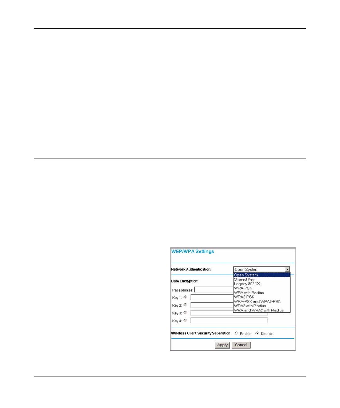
Network Authentication
The WG302 Wireless Access Point is set by default as an open system with no authentication.
When setting up Network Authentication, bear in mind the following:
3-14 Basic Installation and Configuration
v0.1, December 2005
Page 39

Reference Manual for the NETGEAR ProSafe 802.11g Wireless Access Point WG302
• If you are using Access Point mode, then all options are available. In other modes such as
Repeater or Bridge, some options may be unavailable.
• Not all wireless adapters support WPA or WPA2. Windows XP and Windows 2000 with
Service Pack 3 do include the client software that supports WPA. However, client software is
required on the client. Consult the product documentation for your wireless adapter and WPA
or WPA2 client software for instructions on configuring WPA2 settings.
You can configure the WG302 to use the types of network authentication shown in the table below .
Network Authentication Types
Open System Can be used with WEP encryption, or no encryption.
Shared Key WEP must be used. At least one shared key must be entered.
Legacy 802.1x You must configure the Radius Server Settings to use this option.
WPA-PSK You must use TKIP encryption, and enter the WPA passphrase
(Network key).
WPA with Radius You must configure the Radius Server Settings to use this option.
WPA2-PSK WPA2 is a later version of WPA. Only select this if all clients support
WPA2. If selected, you must use AES encryption, and enter the WPA
passphrase (Network key).
WPA-PSK and
WPA2-PSK
WPA2 with Radius WPA2 is a later version of WPA. Only select this if all clients support
WPA and WPA2 with
Radius
This selection allows clients to use either WPA (with TKIP) or WPA2
(with AES). If selected, encryption must be TKIP + AES. The WPA
passphrase (Network key) must also be entered.
WPA2. If selected, you must use AES encryption, and configure the
Radius Server Settings Screen.
This selection allows clients to use either WPA (with TKIP) or WPA2
(with AES). If selected, encryption must be TKIP + AES, and you must
also configure the Radius Server Settings Screen
Data Encryption
Select the data encryption that you want to use. The available options depend on the Network
Authentication setting above (otherwise, the default is None). The Data Encryption settings are
explained in the table below:
Data Encryption Settings
None No encryption is used.
64 bits WEP Standard WEP encryption, using 40/64 bit encryption.
Basic Installation and Configuration 3-15
v0.1, December 2005
Page 40

Reference Manual for the NETGEAR ProSafe 802.11g Wireless Access Point WG302
Data Encryption Settings
128 bits WEP Standard WEP encryption, using 104/128 bit encryption.
152 bits WEP Proprietary mode that will only work with other wireless devices that
support this mode.
TKIP This is the standard encryption method used with WPA.
AES This is the standard encryption method for WPA2. Some clients may
support AES with WPA, but this is not supported by this Access Point.
TKIP + AES This setting supports both WPA and WPA2. Broadcast packets use
TKIP. For unicast (point-to-point) transmissions, WPA clients use TKIP,
and WPA2 clients use AES.
The Passphrases and Keys are explained below:
• Passphrase. T o use the Passphrase to generate the WEP keys, enter a passphrase and click the
Generate Keys button. You can also enter the keys directly. These keys must match the other
wireless stations.
• Key 1, Key 2, Key 3, Key 4. If using WEP, select the key to be used as the default key. Data
transmissions are always encrypted using the default key. The other keys can only be used to
decrypt received data.
• WP A Passphrase (Network Key). If using WPA-PSK, enter the passphrase here. All wireless
stations must use the same passphrase (network key). The network key must be from 8 to 63
characters in length.
Wireless Client Security Separation
If enabled, the associated wireless clients will not be able to communicate with each other. This
feature is used for hotspots and other public access situations. The default is Disabled.
3-16 Basic Installation and Configuration
v0.1, December 2005
Page 41

Reference Manual for the NETGEAR ProSafe 802.11g Wireless Access Point WG302
Before You Change the SSID and WEP Settings
For a new wireless network, print or copy this form and fill in the settings. For an existing wireless
network, the person who set up or is responsible for the network can provide this information. Be
sure to set the Regulatory Domain correctly as the first step. Store this information in a safe place.
• SSID: The Service Set Identification (SSID) identifies the wireless local area network. You
may customize it by using up to 32 alphanumeric characters. Write your SSID on the line.
SSID: _________________________ __ __ ___ ___
Note: The SSID in the wireless access point is the SSID you configure in the wireless adapter
card. All wireless nodes in the same network must be configured with the same SSID.
• Authentication
Circle one: Open System or Shared Key. Choose “Shared Key” for more security.
Note: If you select shared key, the other devices in the network will not connect unless they
are set to Shared Key and have the same keys in the same positions as those in the WG302.
• WEP Encryption Keys
For all four 802.11b keys, choose the Key Size. Circle one: 64, 128, or 152 bits
Key 1: ___________________________________
Key 2: ___________________________________
Key 3: ___________________________________
Key 4: ___________________________________
• WPA-PSK (Pre-Shared Key)WPA2-PSK (Pre-Shared Key)
Record the WPA-PSK key:Record the WPA2-PSK key:
Key: ________________________________
Key: _______________________________
• WPA RADIUS Settings
For WPA, record the following settings for the primary and secondary RADIUS servers:
Server Name/IP Address: Primary _________________
Port: ___________________________________
Secondary __________________
Shared Secret: ___________________________________
• WPA2 RADIUS Settings
For WPA2, record the following settings for the primary and secondary RADIUS servers:
Server Name/IP Address: Primary _________________
Port: ___________________________________
Shared Secret: ___________________________________
Secondary __________________
Use the procedures described in the following sections to configure the WG302.
Basic Installation and Configuration 3-17
v0.1, December 2005
Page 42

Reference Manual for the NETGEAR ProSafe 802.11g Wireless Access Point WG302
Setting up and Testing Basic Wireless Connectivity
Follow the instructions below to set up and test basic wireless connectivity. After this is done, then
you can set up wireless security settings appropriate to your needs.
1. Connect to the WG302.
In the address field of your Web browser, enter the default LAN address of
http://192.168.1.128. Log in with the user name of admin and default password of password,
or using the LAN address and password that you set up.
2. Click the Wireless Settings link in the main menu of the WG302.
The default SSID is NETGEAR-0.
Note: The SSID of any wireless access adapters must match the SSID you configure
in the NETGEAR ProSafe 802.11g Wireless Access Point WG302. If they do
not match, you will not get a wireless connection to the WG302.
3. Select the Country/Region in which the wireless interface will operate.
4. For now, do not make other changes
5. Click Apply to save your changes.
Note: If you are configuring the WG302 from a wireless computer and you change the
SSID, channel, or security settings, you will lose your wireless connection when
you click Apply. You must then change the wireless settings of your computer to
match the new settings.
6. Configure and test your PCs for wireless connectivity.
Set up the wireless adapters of your PCs so that they all have the same SSID and channel that
you configured in the WG302. Check that they have a wireless link and are able to obtain an IP
address by DHCP from the WG302.
Now that your PCs can connect to the WG302, you can configure the wireless security.
3-18 Basic Installation and Configuration
v0.1, December 2005
Page 43

Reference Manual for the NETGEAR ProSafe 802.11g Wireless Access Point WG302
Configuring the Radius Server Settings
Use the following steps to view or change the Radius Server Settings.
1. Connect to the WG302.
In the address field of your Web browser,
enter the default LAN address of
http://192.168.1.128. Log in with the user
name of admin and default password of
password, or log in by using the LAN address
and password that you configured.
2. In the Security menu, click Radius Server
Settings.
3. Enter the settings, and click Apply.
The Radius Server Settings are explained below:
• Authentication/Access Control Radius
Server Configuration. This configuration is
required for authentication using Radius. IP
Address, Port No. and Shared Secret is
required for communication with Radius
Server. A Secondary Radius Server can be
configured which is used on failure on
Primary Radius Server
• IP Address. The IP address of the Radius
Server. The default is 0.0.0.0.
Figure 3-10
• Port Number. Port number of the Radius Server. The default is 1812.
• Shared Secret. This is shared between the Wireless Access Point and the Radius Server while
authenticating the supplicant.
• Re-authentication Time. The time interval in seconds after which the supplicant will be
authenticated again with the Radius Server. The default is 3600 seconds.
• Global-key Re-Key Time. Select this option to enable Re-keying of Global Key. The Global
Key Re-Key can be done based on time interval in seconds or number of packets exchanged
using the global key. The default is 3600 seconds.
Basic Installation and Configuration 3-19
v0.1, December 2005
Page 44
Reference Manual for the NETGEAR ProSafe 802.11g Wireless Access Point WG302
• Update if any station disassociates. Select this option to refresh global key when any stations
disassociated with wireless Access Point.
• Accounting Radius Server Configuration. This configuration is required for accounting
using Radius Server. IP Address, Port Number and Shared Secret is required for
communication with Radius Server. A Secondary Radius Server can be configured which is
used on failure on Primary Radius Server.
• IP Address. The IP address of the Radius Server. The default is 0.0.0.0.
• Port Number. Port number of the Radius Server. The default is 1813.
• Shared Secret. This is shared between the Wireless Access Point and the Radius Server while
authenticating the supplicant.
Configuring Network Authentication
Use the following steps to configure network authentication.
1. Connect to the WG302.
In the address field of your Web browser, enter the default LAN address of
http://192.168.1.128. Log in with the user name of admin and default password of password,
or log in by using the LAN address and password that you configured.
2. If you are using Radius Server Settings, set them up first, as described in “Configuring the
Radius Server Settings” on page 3-19.
3. Set the Network Authentication that you
want to use.
a. On the Security menu, click Security
Profiles Settings.
b. Select the profile that you want.
c. Click Edit to view the Security Profiles
Configuration menu.
d. Choose the type of Network
Authentication that you want from the
list.
Figure 3-11
3-20 Basic Installation and Configuration
v0.1, December 2005
Page 45

Reference Manual for the NETGEAR ProSafe 802.11g Wireless Access Point WG302
Note: You can use WEP with Open System or Shared Key. Choose the
encryption strength, and then enter the Keys as explained in “Entering
WEP Data Encryption Keys” on page 3-21
e. Click Apply to save your settings.
Note: If you use a wireless computer to configure WEP settings, you will be
disconnected when you click Apply. Reconfigure your wireless adapter to
match the new settings or access the wireless access point from a wired
computer to make any further changes.
Entering WEP Data Encryption Keys
You can manually or automatically program the four data encryption keys. These values must be
identical on all PCs and Access Points in your network.
• Automatic: Enter a word or group of printable characters in the Passphrase box and click the
Generate button. The four key boxes are automatically populated with key values.
• Manual: Enter ten hexadecimal digits (any combination of 0-9, a-f, or A-F).
Select which of the four keys is the default.
See http://documentation.netgear.com/reference/enu/wireless/index.htm for a full explanation of
each of these options, as defined by the IEEE 802.11 wireless communication standard.
Restricting Wireless Access by MAC Address
To restrict access based on MAC addresses, follow these steps:
1. Connect to the WG302.
In the address field of your Web browser, enter the default LAN address of
http://192.168.1.128. Log in with the user name of admin and default password of password,
or log in by using the LAN address and password that you configured.
Basic Installation and Configuration 3-21
v0.1, December 2005
Page 46

Reference Manual for the NETGEAR ProSafe 802.11g Wireless Access Point WG302
Note: When configuring the WG302 from a wireless computer whose MAC address
is not in the access control list, if you select Turn Access Control On, you will
lose your wireless connection when you click Apply . You must then access the
wireless access point from a wired computer or from a wireless computer
which is on the access control list to make any further changes.
2. From the Security menu, click the Access Control link to display the Access Control List
(ACL) menu shown below.
Figure 3-12
3. Select the Turn Access Control On check box.
4. Choose to use the local MAC address database stored on the access point, or use the RADIUS
MAC address database stored on a RADIUS server.
• If you choose the RADIUS MAC Address Database, you must configure the RADIUS
Server Settings first.
• If you choose Local MAC Address Database, either select from the list of available
wireless cards the WG302 has found in your area, or enter the MAC address and device
name for a device you plan to use.
3-22 Basic Installation and Configuration
v0.1, December 2005
Page 47

Reference Manual for the NETGEAR ProSafe 802.11g Wireless Access Point WG302
You can usually find the MAC address printed on the wireless adapter. Click Add to add
the wireless device to the access list. Repeat these steps for each additional device you
want to add to the list.
5. Be sure to click Apply to save your wireless access control list settings.
Now, only devices on the MAC ACL will be allowed to wirelessly connect to the WG302.
Basic Installation and Configuration 3-23
v0.1, December 2005
Page 48

Reference Manual for the NETGEAR ProSafe 802.11g Wireless Access Point WG302
3-24 Basic Installation and Configuration
v0.1, December 2005
Page 49

Chapter 4
Management
This chapter describes how to use the management features of your NETGEAR ProSafe 802.11g
Wireless Access Point WG302. To get to these features, connect to the WG302 as described in
“Logging in to the WG302 Using Its Default IP Address” on page 3-9.
Remote Management
Access the Remote Management screen by clicking Remote Management under Management on
the main menu.
Figure 4-1
Enter the Remote Management information.
• Remote Console, Secure Shell (SSH): If set to Enable, the Wireless Access Point will only
allow remote access via Secure Shell and Secure Telnet. The default is Enable.
• SNMP: Enable SNMP to allow the SNMP network management software, such as HP
OpenView, to manage the wireless access point via SNMPv1/v2 protocol.
Management 4-1
v0.1, December 2005
Page 50

Reference Manual for the NETGEAR ProSafe 802.11g Wireless Access Point WG302
• Public Community Name: The community string to allow the SNMP manager to read the
wireless access point's MIB objects. The default is public.
• Private Community Name: The community string to allow the SNMP manager to read and
write the wireless access point's MIB objects. The default is private.
• IP address to Receive T raps: The IP address of the SNMP manager to receive traps sent from
the wireless access point. The default is 0.0.0.0.
Using the Secure Telnet Interface
The WG302 includes a secure Telnet command line interface (CLI). You can access the CLI from
a secure Telnet client over the Ethernet port or over the serial console port.
Note: You must use a secure Telnet client such as Absolute Telnet. Also, when you
configure the client, use the SSH1, 3DES option. If you use the Telnet client to
connect over the Ethernet port, use the IP address of the WG302 as the host name.
How to Use the CLI via the Console Port
1. Using the null-modem cable, connect a VT100/ANSI terminal or a workstation to the port
labeled Console.
If you attached a PC, Apple Macintosh, or UNIX workstation, start a secure
terminal-emulation program.
2. Configure the terminal-emulation program to use the following settings:
• Baud rate: 9600 bps
• Data bits: 8
• Parity: none
•Stop bit: 1
• Flow control: none
These settings appear below the connector on the back panel.
4-2 Management
v0.1, December 2005
Page 51

Reference Manual for the NETGEAR ProSafe 802.11g Wireless Access Point WG302
3. Press the return key, and the screen below should appear.
Figure 4-2
The login name is admin and password is the default password.
After successful login, the screen should show the (Access Point Name)> prom pt. In this
example, the prompt is netgear74F35E.
Enter help to display the CLI command help.
CLI Commands
The CLI commands are listed in Appendix C, “Command Line Reference.”
SNMP Remote Management
Enable SNMP to allow SNMP network management software such as HP OpenView to manage
the wireless access point via the SNMPv1/v2 protocol.
1. Click Enable to use the SNMP remote management feature.
2. Fill in the fields according to the requirements of your location.
• Public Community Name. (Default: public) The community string to allow the SNMP
manager to read the MIB objects of the WG302.
• Private Community Name. (Default: private) The community string to allow the SNMP
manager to read and write the MIB objects of the WG302.
• Manager IP address. Enter the IP address of the SNMP manager. If this is set to
255.255.255.255, any SNMP manager is allowed.
Management 4-3
v0.1, December 2005
Page 52

Reference Manual for the NETGEAR ProSafe 802.11g Wireless Access Point WG302
• IP address to Receive Traps. Enter the IP address of the SNMP manager to receive traps
sent from the wireless Access Point. If you don't want Traps to be sent, leave this at the
default value of 0.0.0.0
3. Be sure to click Apply to save your changes.
Viewing the Activity Log
From the WG302 main menu, under the Information heading, click Activity Log.
Figure 4-3
You can use a SysLog server to view the Activity Log. If you have a SysLog server on your LAN,
then enable the SysLog. If enabled, you must enter the IP address of your SysLog server and the
port number that your SysLog server uses.
• SysLog Server IP address: The access point sends all the SysLog to the specified IP address if
SysLog option is enabled. Default: 0.0.0.0
4-4 Management
v0.1, December 2005
Page 53

Reference Manual for the NETGEAR ProSafe 802.11g Wireless Access Point WG302
• Port: The port number configured in the SysLog server on your LAN. The default is 514
The Activity Log Window displays the Access Point system activity.
You can click Refresh to update the display. To save the log contents into a file on your PC, click
Save As and save the file to a disk drive.
Viewing General Information
The General information is a summary of the WG302 configuration settings. From the WG302
main menu, click General to view the screen shown below.
Figure 4-4
Management 4-5
v0.1, December 2005
Page 54

Reference Manual for the NETGEAR ProSafe 802.11g Wireless Access Point WG302
Table 4-1. General Information Fields
Field Description
Access Point Information
Access Point Name
(NetBIOS name)
Country/Region The domain or region for which the wireless access point is licensed for
Firmware Version The version of the firmware currently installed.
Access Point Mode The operating mode of the WG302: Access Point, Point-to-point bridge,
VLAN (802.1Q) Indicates if VLAN support is enabled. The default is disabled.
Management VLAN ID Displays the VLAN ID.
Current IP Settings
IP Address The IP address of the wireless access point.
Subnet Mask The subnet mask for the wireless access point.
Default Gateway The default gateway for the wireless access point communication.
DHCP Client If the DHCP Client is enabled, the current IP address was obtained
MAC Address The Media Access Control address (MAC address) of the wireless
Current Wireless Settings
Channel/Frequency The channel the wireless port uses. The default channel setting is 11.
The name of the access point, which you can configure.
use. It may not be legal to operate this wireless access point in a region
other than one of those identified in this field.
Multi-point bridge or Repeater.
from a DHCP server on your network. Disabled indicates a static IP
configuration.
access point’s Ethernet port.
For the frequencies used on each channel, see
http://documentation.netgear.com/reference/enu/wireless/index.htm.
Security Profiles For each Security Profile, the following information is displayed: Profile
name, SSID, security option, VLAN ID, and enabled/disabled.
4-6 Management
v0.1, December 2005
Page 55

Reference Manual for the NETGEAR ProSafe 802.11g Wireless Access Point WG302
Viewing Statistics
The Statistics screen provides LAN and WLAN statistics. From the WG302 main menu, click
Statistics under the Information heading to view the screen shown in Figure 4-5.
Figure 4-5
Management 4-7
v0.1, December 2005
Page 56

Reference Manual for the NETGEAR ProSafe 802.11g Wireless Access Point WG302
Viewing the Available Wireless Station List
The Available Wireless Station List contains a table of all IP devices associated with the wireless
access point for the Wired Network Name (SSID).
From the WG302 main menu, under the Information heading,
click Available Wireless Station List to view the list. The fields
in the list are explained below.
Figure 4-6
Table 4-2. Available Wireless Station List
Field Description
Wired Ethernet Received/Transmitted
Packets The number of packets sent since the WG302 was restarted.
Bytes The number of bytes sent since the WG302 was restarted.
For Each Wireless Security
Profile
Unicast Packets The Unicast packets sent since the WG302 was restarted.
Broadcast Packets The Broadcast packets sent since the WG302 was restarted.
Multicast Packets The Multicast packets sent since the WG302 was restarted.
Total Packets The Wireless packets sent since the WG302 was restarted.
Total Bytes The Wireless bytes sent since the WG302 was restarted.
Refresh button Click the Refresh button to update the statistics on this screen.
Received/Transmitted
For each device, the table shows the Station ID, MAC address, IP Address, and Status (whether the
device is allowed to communicate with the wireless access point or not).
4-8 Management
v0.1, December 2005
Page 57

Reference Manual for the NETGEAR ProSafe 802.11g Wireless Access Point WG302
Note that if the wireless access point is rebooted, the table data is lost until the wireless access
point rediscovers the devices. To force the wireless access point to look for associated devices,
click the Refresh button.
Note: A wireless network can include multiple wireless access points that use the same
network name (SSID). This extends the reach of the wireless network. Users can
roam from one access point to another, providing seamless network connectivity. If
this is the case, only the stations associated with this access point are shown in the
Available Station List.
Upgrading the Wireless Access Point Firmware
Warning: When uploading firmware to the WG302 Wireless Access Point, do not
interrupt the W eb browser by closing the window, clicking a link, or loading a
new page. If the browser is interrupted, the upload may fail, corrupt the
firmware, and render the WG302 completely inoperable
You cannot upgrade the firmware from a computer that is connected to the WG302 with a wireless
link. You must use a computer that is connected to the WG302 with an Ethernet cable.
The WG302 Wireless Access Point firmware is stored in FLASH memory and can be upgraded as
new firmware is released by NETGEAR. Y ou can download the upgrade files from the NETGEAR
Web site. If the upgrade file is compressed (.ZIP file), you must first extract the image (.IMG) file
before you send it to the wireless access point. The upgrade file can be sent using your browser.
Note: The Web browser used to upload new firmware into the WG302 must support
HTTP uploads, such as Microsoft Internet Explorer 6.0 or above, or Netscape
Navigator 4.78 or above.
Use the following steps to upgrade the firmware:
1. Download the file from NETGEAR, save it to your hard disk, and unzip it.
2. If you want to save your configuration settings, see “Backing up and Restoring the
Configuration” on page 4-10.
3. From the main menu Management section, click the Upgrade Firmware link.
4. In the Upgrade Firmware menu, click the Browse button and browse to the location of the
image (.IMG) upgrade file.
Management 4-9
v0.1, December 2005
Page 58

Reference Manual for the NETGEAR ProSafe 802.11g Wireless Access Point WG302
5. Click Upload.
When the upload completes, your wireless access point automatically restarts. The upgrade
process typically takes about one minute.
In some cases, you may need to reconfigure the wireless access point after upgrading.
Configuration File Management
The WG302 Wireless Access Point settings are stored in the wireless access point in a
configuration file. This file can be saved (backed up) to a computer, retrieved (restored) from a
computer, or cleared to factory default settings.
Click Backup/Restore Settings under the Management heading to go to the menu shown in
Figure 4-7.
Figure 4-7
The three options displayed are described in the following sections.
Backing up and Restoring the Configuration
T o save your settings, click Backup. Your browser extracts the configuration file from the wireless
access point and prompts you for a location on your computer to store the file. You can give the
file a meaningful name at this time, such as WG302.cfg.
4-10 Management
v0.1, December 2005
Page 59

Reference Manual for the NETGEAR ProSafe 802.11g Wireless Access Point WG302
To restore your settings from a saved configuration file, enter the full path to the file on your
computer or click the Browse button to locate the file. When you have located it, click the Restore
button to upload the file. After completing the upload, the WG302 reboots automatically.
Erasing the Configuration
You can erase the wireless access point configurations and return to the factory default settings.
After you erase the configurations, the wireless access point’s password will be password, the
SSID will be NETGEAR, the DHCP client will be disabled, the default LAN IP address will be
192.168.1.128, and the access point name is reset to the name printed on the label on the bottom of
the unit.
Using the Reset Button to Restore Factory Default Settings
If you do not know the login password or IP address, you can still restore the factory default
configuration settings with the Reset button. This button is on the rear panel of the wireless access
point (see “Hardware Description” on page 2-7). The reset button has two functions:
• Reboot. When pressed and released, the Wireless Access Point reboots (restart).
• Reset to Factory Defaults. When pressed and held down, it clears all data and restores all
settings to the factory default values.
To clear all data and restore the factory default values:
1. Hold the Reset Button until the LEDs blink twice, usually more than five seconds.
2. Release the Reset Button.
The factory default configuration has now been restored, and the WG302 is ready for use.
Management 4-11
v0.1, December 2005
Page 60

Reference Manual for the NETGEAR ProSafe 802.11g Wireless Access Point WG302
Changing the Administrator Password
The default password is password. NETGEAR recommends that you change this password to a
more secure password. You cannot change the administrator login name.
From the WG302 main menu,
click Change Password to go to
the menu shown below.
To change the password, first
enter the old password, and
then enter the new password
twice. Click Apply to save your
change.
Figure 4-8
4-12 Management
v0.1, December 2005
Page 61

Reference Manual for the NETGEAR ProSafe 802.11g Wireless Access Point WG302
AutoCell Rogue AP Detection
The AutoCell feature provides added security. It can detect rogue APs and wireless stations and
exclude them from connecting to the WG302 Wireless Access Point.
From the WG302 main menu,
click Rogue AP Detection to
view this menu.
• You can click Rescan to
discover the APs.
• Click Authorize to add any
AP to the Authorized AP
List. Click Delete to
remove an AP from the list.
• Optionally, you can export
or import lists of authorized
APs.
Figure 4-9
Management 4-13
v0.1, December 2005
Page 62

Reference Manual for the NETGEAR ProSafe 802.11g Wireless Access Point WG302
AutoCell Rogue Station Detection
The AutoCell feature provides added security. It can detect rogue APs and wireless stations and
exclude them from connecting to the WG302 Wireless Access Point.
From the WG302 main menu,
click Rogue Station Detection
to view this menu.
• Click Rescan to discover
the stations.
• Click Authorize to add any
station to the Authorized
Station List. Click Delete to
remove an station from the
list.
• Optionally, you can export
or import lists of authorized
stations.
Figure 4-10
.
4-14 Management
v0.1, December 2005
Page 63

Chapter 5
Advanced Configuration
This chapter describes how to configure the advanced features of your NETGEAR ProSafe
802.11g Wire less Access Point WG302. The following list describes the advanced features:
• IP Settings: Use the AP as a DHCP server for wireless clients.
• Wireless Settings: Set up AutoCell and configure advanced wireless LAN parameters.
• Access Point Settings: Enable wireless bridging and repeating.
• TBD: New features under the Advanced heading, like NAT and Load Balancing.
You can find these features under the Advanced heading in the main menu.
Understanding Advanced IP Settings for Wireless Clients
If you want the AP to act as a DHCP server gateway for wireless clients, use this feature. The AP
can accept both static and DHCP clients.
Figure 5-1
Advanced Configuration 5-1
v0.1, December 2005
Page 64

Reference Manual for the NETGEAR ProSafe 802.11g Wireless Access Point WG302
The following list provides information about how to configure DHCP settings.
• Use AP as DHCP Server: Y ou may turn on this option and the Access Point will funct ion as a
DHCP Server for Wireless Clients only. The Access Point will provide the pre-configured
TCP/IP configurations for all wireless stations connected to this Access Point.
There are two options available for managing the wireless clients:
— Accept DHCP Enabled Wireless Clients Only: The Access Point can only provide the
TCP/IP configurations to those wireless clients with the DHCP enabled.
— Accept Both DHCP Enabled and Static IP Configured Wireless Clients: The Access
Point will support wireless clients with the DHCP enabled and the static IP configured.
If you use the AP as a DHCP server, you must configure the following TCP/IP configurations for
using Access Point as a DHCP Server for Wireless Clients.
• Starting IP Address: Type the starting IP address can be assigned from the DHCP server on
this Access Point.
• Ending IP Address: Type the Ending IP address can be assigned from the DHCP server on
this Access Point
• Subnet Mask: The Access Point will assign the specified subnet mask to the connected
wireless stations.
• Gateway Address: The Access Point will assign this IP address as the default gateway for any
traffic beyond the local network.
• Primary DNS Server: The Access Point will assign this IP address as the primary Domain
Name Server used by the connected wireless stations.
• Secondary DNS Server: The Access Point will assign this IP address as the secondary
Domain Name Server used by the connected wireless stations.
• Primary WINS Server: The Access Point will assign this IP address as the primary WINS
Server used by the connected wireless stations.
• Secondary WINS Server: The Access Point will assign this IP address as the secondary
WINS Server used by the connected wireless stations.
• Lease: The lease time for the IP address assigned. The wireless client user is required to renew
the IP address as soon as the lease is expired.
5-2 Advanced Configuration
v0.1, December 2005
Page 65

Reference Manual for the NETGEAR ProSafe 802.11g Wireless Access Point WG302
Configuring Advanced Wireless LAN Settings
This section describes the advanced wireless settings menu, which enables configuration of the
following features:
• AutoCell RF management
• Wi-Fi multimedia (WMM) setup
• Hotspot settings
• Advanced wireless parameters
AutoCell Overview
AutoCell provides advanced RF wireless management features that improve performance and
enhance security.
Table 5-1. What does AutoCell do?
Problem AutoCell Settings
Erosion of privacy You can enab le these two settings:
• Enhanced RF Security (Default: Disabled): Makes your Wi-Fi network
nearly undetectable by neighbors and hackers.
• Rogue Device Detection (Default: Disabled): Blocks rogue wireless
devices from connecting to your network.
Diminishing performance from
multiple APs installed in one
area.
The Auto RF Management feature (Default: Enabled) manages APs
and clients load-balance traffic across underutilized APs.
Complexity of installation With the Auto RF Management feature (Default: Enabled), the APs can
be put in any convenient location and in any density.
Increasing interference The Auto RF Management feature (Default: Enabled) lets clients and
APs avoid interference from neighbors and other unexpected sources.
AutoCell’s self-organizing micro cells provide an additional level of privacy for enterprises.
AutoCell clients are highly-recommended for Enhanced RF Security.
Advanced Configuration 5-3
v0.1, December 2005
Page 66

Reference Manual for the NETGEAR ProSafe 802.11g Wireless Access Point WG302
AutoCell AP/Client Interaction
AutoCell’s self-organizing micro cells provide performance benefits and an additional level of
privacy for enterprises.
• Automatic Transmit Power Control. An AP with AutoCell enabled coordinates the RF
transmit power level of AutoCell-enabled clients. This creates client micro-cells and reduces
co-channel interference with other clients and APs on the same frequency. It also improves
overall throughput and performance.
• Automatic Load-Balancing. An AutoCell-enabled client seeks out and associates with the
lightest loaded AutoCell-enabled AP available.
• Rapid Roaming. An AutoCell-enabled client quickly distinguishes movement from RF
anomalies such as arbitrary and momentary changes in the surrounding RF domain. When it
detects true movement, the client immediately seeks the best available AP at the highest data
rate possible instead of waiting for the data rate to decline. This feature does not require
AutoCell-enabled APs.)
Additional AutoCell View Management Options
Figure 5-2
AutoCell V iew is a management tool that provides sophisticated views of your wireless network so
that you can manage the wireless communications easily from a simple console.
5-4 Advanced Configuration
v0.1, December 2005
Page 67

Reference Manual for the NETGEAR ProSafe 802.11g Wireless Access Point WG302
AutoCell Configuration Options
There are three AutoCell configuration setting
choices:
• Auto RF Management: Enabled by default.
• Enhanced RF Security: Disabled by default.
• Rogue Device Detection: Disabled by
default.
These options are discussed below.
Auto RF Management
Note: Channel selection and power management is automatically adjusted by the
AutoCell Auto RF Management option. The Auto RF Management option is
enabled by default.
Figure 5-3
In this mode, AutoCell APs and clients load-balance traffic across underutilized APs. This mode
avoids interference from neighbors, clients, APs, and other unexpected sources.
Enhanced RF Security
Note: Broadcast Wireless Network Name (SSID) is automatically turned off when you
select the AutoCell Enhanced RF Security option.
In this mode, AutoCell shrinks the size of coverage to the minimum to reach clients but also
shrinks the size of the beacons that access points use to announce their presence. This mode makes
an enterprise wireless LAN nearly invisible to users outside an office building.
Rogue Device Detection
The AutoCell Rogue Device Detection feature lets you identify and block wireless devices that
should never be given access to the wireless network.
Advanced Configuration 5-5
v0.1, December 2005
Page 68

Reference Manual for the NETGEAR ProSafe 802.11g Wireless Access Point WG302
Wi-Fi Multimedia (WMM) Setup
WMM is a subset of the 802.11e standard. WMM allows wireless traffic to have a range of
priorities, depending on the kind of data. Time-dependent information, such as video or audio, will
have a higher priority than normal traffic. For WMM to function correctly, wireless clients must
also support WMM.
WMM Support: Select Yes or No as required on the Advanced Wireless Settings menu. The
default is No.
Hotspot Settings
If you want the access point (AP) to capture and redirect all HTTP (TCP , port 80) requests, use this
feature. For example, a hotel might want all wireless connections to go to its server to start a
billing transaction.
Figure 5-4
Enter the URL of the Web server where you wish to redirect HTTP requests.
5-6 Advanced Configuration
v0.1, December 2005
Page 69

Reference Manual for the NETGEAR ProSafe 802.11g Wireless Access Point WG302
Configuring Wireless LAN Parameters
The default advanced wireless LAN parameter settings usually work well. If you want the AP to
operate in Super-G mode, use this feature.
Figure 5-5
Table 5-1 describes the advanced wireless parameters.
Table 5-1. Advanced Wireless LAN Settings Fields
Field Description
Enable SuperG Mode Click Enable to enable SuperG Mode.
RTS Threshold The pa cket size used to determine whether it should use the CSMA/CD (Carrier
Sense Multiple Access with Collision Detection) or the CSMA/CA (Carrier
Sense Multiple Access with Collision Avoidance) mechanism for packet
transmission.
Fragmentation Length This is the maximum packet size used for fragmentation. Packets larger than
the size programmed in this field will be fragmented. The Fragment Threshold
value must be larger than the RTS Threshold value.
Beacon Interval Specifies the data beacon rate between 20 and 1004.
DTIM Interval The Delivery Traffic Indication Message specifies the data beacon rate between
1 and 255.
Preamble Type A long transmit preamble may provide a more reliable connection or slightly
longer range. A short transmit preamble gives better performance. Long is the
default
Antenna Select the desired antenna for transmitting and receiving. Auto is the default.
Advanced Configuration 5-7
v0.1, December 2005
Page 70

Reference Manual for the NETGEAR ProSafe 802.11g Wireless Access Point WG302
Wireless Bridging and Repeating
The WG302 Wireless Access Point lets you build large bridged wireless networks.
Note: All bridge mode options are not available when AutoCell Auto RF Management is
enabled (the default setting).
Examples of wireless bridged configurations are:
• Point-to-Point Bridge. The WG302 communicates with another bridge-mode wireless station.
See “Point-to-Point Bridge Configuration” on page 5-10.
• Multi-Point Bridge. The WG102 is the “master” for a group of bridge-mode wireless stations.
Then all traffic is sent to this “master,” rather than to other access points. See “Multi-Point
Bridge Configuration” on page 5-11.
5-8 Advanced Configuration
v0.1, December 2005
Page 71

Reference Manual for the NETGEAR ProSafe 802.11g Wireless Access Point WG302
• Repeater with Wireless Client Association. Sends all traffic to the remote AP. See “Repeater
with Wireless Client Association” on page 5-12.
These configurations can be set up
from the Advanced Access Point
Settings menu, shown to the right.
Figure 5-6
Advanced Configuration 5-9
v0.1, December 2005
Page 72

Reference Manual for the NETGEAR ProSafe 802.11g Wireless Access Point WG302
Point-to-Point Bridge Configuration
In Point-to-Point Bridge mode, the WG302 communicates with another bridge-mode wireless
station. In addition, you can enable client associations with this WG302. You must enter the MAC
address of the other bridge-mode wireless station in the field provided. Use WEP to protect this
communication. The figure below shows an example of Point-to-Point Bridge mode.
Both APs are in
Point-to-Point Bridge mode.
AP 1
AP 2
Router
Internet
192.168.0.1
PCs
LAN Segment 1
Figure 5-7
Hub or Switch
PCs
LAN Segment 2
Follow the steps below to set up a Point-to-Point Bridge configuration.
1. Configure the WG302 (AP1) on LAN Segment 1 in Point-to-Point Bridge mode.
2. Configure the other access point (AP2) on LAN Segment 2 in Point-to-Point Bridge mode.
AP 1 must have AP 2’s MAC address in its Remote MAC Address field and AP 2 must have
AP 1’s MAC address in its Remote MAC Address field.
3. Configure and verify the following for both access points:
• Verify the LAN network configuration of the access points. Both must be configured to
operate in the same LAN network address range as the LAN devices
• Both APs must use the same ESSID, Channel, authentication mode, if any, and security
settings if security is in use.
4. Verify connectivity across the LAN 1 and LAN 2.
A computer on either LAN segment should be able to connect to the Internet or share files and
printers of any other PCs or servers connected to LAN Segment 1 or LAN Segment 2.
5-10 Advanced Configuration
v0.1, December 2005
Page 73

Reference Manual for the NETGEAR ProSafe 802.11g Wireless Access Point WG302
Multi-Point Bridge Configuration
Set up a Multi-Point Bridge only if this WG102 is the “master” for a group of bridge-mode
wireless stations. Then all traffic is sent to this “master,” rather than to the other access points. In
addition, you can enable client associations with this WG302.
• You must enter the MAC addresses of the other access points in the fields provided.
• The other bridge-mode wireless stations must be set to Point-to-Point Bridge mode, using the
MAC address of this WG102 as the Remote MAC Address.
• Use WEP to protect this traffic.
The figure below shows an example of a Multi-Point Bridge mode configuration.
Point-to-Multi-Point
Bridge mode
Internet
192.168.0.1
LAN Segment 1
AP 1
Router
PCs
“Master AP”
Point-to-Point
Bridge Mode
Hub or Switch
Point-to-Point
Bridge Mode
AP 2
PCs
LAN Segment 2
Hub or Switch
LAN Segment 3
Figure 5-8
Follow the steps below to set up the Multi-Point Bridge configuration.
1. Configure the Operating Mode of the WG302 Wireless Access Points.
• Because it is in the central location, configure WG302 (AP 1) on LAN Segment 1 in
Point-to-Multi-Point Bridge mode. The MAC addresses of AP2 and AP3 are required in
AP1.
AP 3
PCs
• Configure WG302 (AP 2) on LAN Segment 2 in Point-to-Point Bridge mode with the
Remote MAC Address of AP1.
Advanced Configuration 5-11
v0.1, December 2005
Page 74

Reference Manual for the NETGEAR ProSafe 802.11g Wireless Access Point WG302
• Configure the WG302 (AP3) on LAN 3 in Point-to-Point Bridge mode with the Remote
MAC Address of AP1.
2. Verify the following for all access points:
• The LAN network configuration of the WG302 Wireless Access Points are configured to
operate in the same LAN network address range as the LAN devices
• Only one AP is configured in Point-to-Multi-Point Bridge mode, and all the others are in
Point-to-Point Bridge mode.
• All APs must be on the same LAN. That is, all the APs LAN IP address must be in the
same network.
• If using DHCP, all WG302 Wireless Access Points should be set to “Obtain an IP address
automatically (DHCP Client)” in the IP Address Source portion of the Basic IP Settings
menu.
• All WG302 Wireless Access Points use the same SSID, Channel, authentication mode, if
any, and encryption in use.
• All Point-to-Point APs must have AP2’s MAC address in its Remote AP MAC address
field.
3. Verify connectivity across the LANs.
• A computer on any LAN segment should be able to connect to the Internet or share files
and printers with any other PCs or servers connected to any of the three LAN segments.
• Wireless stations will not be able to connect to the WG302 Wireless Access Points in the
illustration above. If you require wireless stations to access any LAN segment, you can
use additional WG302 Wireless Access Points configured in Wireless Access Point mode
to any LAN segment.
Note: You can extend this multi-point bridging by adding additional WG302s configured
in Point-to-Point mode for each additional LAN segment. Furthermore, you can
extend the range of the wireless network with NETGEAR wireless antenna
accessories.
Repeater with Wireless Client Association
In this mode, the WG302 Wireless Access Point sends all traffic to the remote AP. For repeater
mode, you must enter the MAC address of the remote “parent” access point. You can also enter the
address of the “child” access point. Note that the following restrictions apply:
•You do not have the option of disabling client associations with this WG302.
5-12 Advanced Configuration
v0.1, December 2005
Page 75

Reference Manual for the NETGEAR ProSafe 802.11g Wireless Access Point WG302
• You cannot configure a sequence of parent/child APs. You are limited to only one parent/child
AP pair.
The figure below shows an example of a Repeater Mode configuration.
AP 1
Wireless PC
Associated with AP 1
Router
Internet
192.168.0.1
PCs
Figure 5-9
Parent AP in Repeater Mode
Wireless PC
Associated with AP 2
AP 2
Child AP in Repeater Mode
Wireless PC
Associated with AP 2
To se t up a repeater with wirele ss client association, follow the steps below:
1. Configure the Operating Mode of the WG302 Wireless Access Points.
• Configure AP 1 on LAN Segment 1 as the Parent in Repeater mode with the its own MAC
address in the Parent AP MAC Address field, and the MAC Address of the ‘downstream’
AP (AP 2) in the Child AP MAC Address field.
• Configure AP 2 in the Child Repeater mode with its MAC addresses as in the Child AP
MAC Address field and the MAC address of the ‘upstream’ AP (AP 1) in the Parent MAC
Address field.
2. Verify the following for all access points:
• The LAN network configuration of the WG302 Wireless Access Points are configured to
operate in the same LAN network address range as the LAN devices
• All APs must be on the same LAN. That is, all the APs LAN IP address must be in the
same network.
• If using DHCP, all WG302 Wireless Access Points should be set to “Obtain an IP address
automatically (DHCP Client)” in the IP Address Source portion of the Basic IP Settings
menu.
Advanced Configuration 5-13
v0.1, December 2005
Page 76

Reference Manual for the NETGEAR ProSafe 802.11g Wireless Access Point WG302
• All WG302 Wireless Access Points use the same SSID, Channel, authentication mode, if
any, and encryption in use.
3. Verify connectivity across the LANs.
A computer on any LAN segment should be able to connect to the Internet or share files and
printers with any other PCs or servers connected to any of the three WLAN segments.
Note: You can extend this repeating by adding up to two more WG302s configured in
repeater mode. However, since repeaters communicate in half-duplex mode, the
bandwidth decreases as you add repeaters to the network. Also, you can extend the
range of the wireless network with NETGEAR wireless antenna accessories.
Configuring NAT
TBD
Configuring QoS Queues
Configuring Quality of Service (QoS) on the WG302 Wireless Access Point consists of setting
parameters on existing queues for different types of wireless traffic, and effe ctively specifying
minimum and maximum wait times (via Contention Windows) for transmission. The settings
described here apply to data transmission behavior on the access point only, not to that of the client
stations.
Note: For the Guest interface, QoS queue settings apply to the access point load as a
whole (both BSSes together). On a two-radio access point these settings apply to
both radios but the traffic for each radio is queued independently . (The exception to
this is guest traffic as noted below.) Internal and Guest network traffic is always
queued together within each radio. This is the case on both one-radio and two-radio
APs.
5-14 Advanced Configuration
v0.1, December 2005
Page 77

Reference Manual for the NETGEAR ProSafe 802.11g Wireless Access Point WG302
QoS on the access point leverages existing information in the IP packet header related to Type of
Service (ToS). The access point examines the ToS field in the headers of all packets that pass
through the AP. Based on the value in a packet’s ToS field, the AP prioritizes the packet for
transmission by assigning it to one of the queues. A different type of data is associated with each
queue. You can configure parameters that determine how each queue is treated when it is sent by
the access point.
Setting up Guest Access
Out-of-the-box Guest Interface features allow you to configure the WG302 Wireless Access Point
for controlled guest access to an isolated network. You can configure the same access point to
broadcast and function as two different wireless networks: a secure “Internal” LAN and a public
“Guest” network.
Guest clients can access the guest network without a username or password. When guests log in,
they see a guest Welcome screen (also known as a captive portal).
You can define unique parameters for guest connectivity and isolate guest clients from other more
sensitive areas of the network. No security is provided on the guest network; only plain-text
security mode is allowed.
Simultaneously, you can configure a secure internal network (using the same access point as your
guest interface) that provides full access to protected information behind a firewall and requires
secure login or certificates for access.
Advanced Configuration 5-15
v0.1, December 2005
Page 78

Reference Manual for the NETGEAR ProSafe 802.11g Wireless Access Point WG302
5-16 Advanced Configuration
v0.1, December 2005
Page 79

Chapter 6
Troubleshooting
This chapter provides information about troubleshooting your NETGEAR ProSafe 802.11g
Wireless Access Point WG302. After each problem description, instructions are given to help you
diagnose and solve the problem. For the common problems listed, go to the section indicated.
• Is the WG302 on?
• Have I connected the wireless access point correctly?
Go to“Installing the WG302 Wireless Access Point” on page 3-5.
• I cannot remember the wireless access point’s configuration password.
Go to “Changing the Administrator Password” on page 4-12.
If you have trouble setting up your WG302, check the tips below.
No lights are lit on the access point.
It takes a few seconds for the power indicator to light up. Wa it a minute and check the power light
status on the access point.
If the access point has no power.
• Make sure the power cord is connected to the access point.
• Make sure the power adapter is connected to a functioning power outlet. If it is in a power
strip, make sure the power strip is turned on. If it is plugged directly into the wall, verify that it
is not a switched outlet.
• Make sure you are using the correct NETGEAR power adapter supplied with your access
point.
Troubleshooting 6-1
v0.1, December 2005
Page 80

Reference Manual for the NETGEAR ProSafe 802.11g Wireless Access Point WG302
The Wireless LAN activity light does not light up.
The access point’s antennae are not working.
• If the Wireless LAN activity light stays off, disconnect the adapter from its power source and
then plug it in again.
• Make sure the antennas are tightly connected to the WG302.
• Contact NETGEAR technical support if the Wireless LAN activity light remains off.
The LAN light is not lit.
There is a hardware connection problem. Check these items:
• Make sure the cable connectors are securely plugged in at the access point and the network
device (hub, switch, or router). A switch, hub, or router must be installed between the access
point and the Ethernet LAN or broadband modem.
• Make sure the connected device is turned on.
• Be sure the correct cable is used. Use a standard Category 5 Ethernet patch cable. If the
network device has Auto Uplink™ (MDI/MDIX) ports, you can use either a crossover cable or
a normal patch cable.
I cannot access the Internet or the LAN with a wireless
capable computer.
There is a configuration problem. Check these items:
• You may not have restarted the computer with the wireless adapter to have TCP/IP changes
take effect. Restart the computer.
• The computer with the wireless adapter may not have the correct TCP/IP settings to
communicate with the network. Restart the computer and check that TCP/IP is set up properly
for that network. The usual setting for Windows the Network Properties is set to “Obtain an IP
address automatically.”
• The access point’s default values may not work with your network. Check the access point
default configuration against the configuration of other devices in your network.
6-2 Troubleshooting
v0.1, December 2005
Page 81

Reference Manual for the NETGEAR ProSafe 802.11g Wireless Access Point WG302
I cannot connect to the WG302 to configure it.
Check these items:
• The WG302 is properly installed, LAN connections are OK, and it is powered on. Check that
the LAN port LED is on (amber indicating a 10 Mbps Ethernet connection or green indicating
a 100 Mbps Ethernet connection) to verify that the Ethernet connection is OK.
• The default configuration of the WG302 is for a static IP address of 192.168 .1.128 and a Mask
of 255.255.255.0 with DHCP disabled. Make sure your network configuration settings are
correct.
• If you are using the NetBIOS name of the WG302 to connect, ensure that your computer and
the WG302 are on the same network segment or that there is a WINS server on your network.
• If your computer is set to “Obtain an IP Address automatically” (DHCP client), restart it.
• If your computer uses a Fixed (Static) IP address, ensure that it is using an IP Address in the
range of the WG302. The WG302 default IP Address is 192.168.1.128 and the default Subnet
Mask is 255.255.255.0.
When I enter a URL or IP address I get a timeout error.
A number of things could be causing this. Try the following troubleshooting steps.
• Check whether other PCs work. If they do, ensure that your PCs TCP/IP settings are correct. If
using a Fixed (Static) IP Address, check the Subnet Mask, Default Gateway, DNS, and IP
Addresses.
• If the PCs are configured correctly, but still not working, ensure that the WG302 is connected
and turned on. Connect to it and check its settings. If you cannot connect to it, check the LAN
and power connections.
• If the WG302 is configured correctly, check your Internet connection (DSL/Cable modem
etc.) to make sure that it is working correctly.
•Try again.
Troubleshooting 6-3
v0.1, December 2005
Page 82

Reference Manual for the NETGEAR ProSafe 802.11g Wireless Access Point WG302
Using the Reset Button to Restore Factory Default Settings
The Reset button (see “Rear Panel” on page 2-8) has two functions:
• Reboot. When pressed and released quickly, the WG302 will reboot (restart).
• Reset to Factory Defaults. This button can also be used to clear ALL data and restore ALL
settings to the factory default values.
To clear all data and restore the factory default values:
1. Power off the WG302 and power it back on.
2. Use something with a small point, such as a pen, to press the Reset button in and hold it in for
at least 5 seconds.
3. Release the Reset button.
The factory default configuration has now been restored, and the WG302 is ready for use.
6-4 Troubleshooting
v0.1, December 2005
Page 83

Appendix A
Specifications
Parameter NETGEAR ProSafe 802.11g Wireless Access Point WG302
Network Management Web-based configuration and status monitoring
Maximum
Status LEDs Power/Ethernet LAN/Wireless LAN/Test
Power
Electromag
Environmental Specifications Operating temperature: 0 to 50° C
Da
Maximum Computers Per
Wireless Network:
80
Radio Data Rate
802.11b and g
Operating Frequencies
80
Antenn
Clients Limited by the amount of wireless network traffic generated by each node;
typically 30 to 70 nodes.
Adapter 12V DC, 1 A
netic Compliance FCC Part 15 Class B and Class E
Operating humidity: 5-95%, non-condensing
ta Encoding: 802.11b: 1 and 2 Mbps, Direct Sequence Spread Spectrum (DSSS)
802.11b: 5.5 and 11 Mbps, Complementary Code Keying (CCK)
802.11g: All rates, Orthogonal Frequency Division Multiplexing (OFDM)
Limited by the amount of wireless network traffic generated by each node.
Typically 30-70 nodes.
2.11b and g
2.11g Encryption 40-bits (also called 64-bits), 128- and 152-bits WEP data encryption
a: Please refer to page iv
1, 2, 5.5, 6, 9, 11, 12, 18, 24, 36, 48, 54, and 108 Mbps (Auto-rate capable)
2.412 ~ 2.462 GHz (US)
2.412 ~ 2.484 GHz (Japan)
2.412 ~ 2.472 GHz (Europe ETSI)
Specifications A-1
v0.1, December 2005
Page 84

Reference Manual for the NETGEAR ProSafe 802.11g Wireless Access Point WG302
A-2 Specifications
v0.1, December 2005
Page 85

Appendix B
Wireless Networking Basics
This chapter provides an overview of Wireless networking.
Wireless Networking Overview
The WG302 Wireless Access Point conforms to the Institute of Electrical and Electronics
Engineers (IEEE) 802.11b and 802.11g standards for wireless LANs (WLANs).
On an 802.11b or g wireless link, data is encoded using direct-sequence spread-spectrum (DSSS)
technology and is transmitted in the unlicensed radio spectrum at 2.5GHz. The maximum data rate
for the 802.11b wireless link is 1 1 Mbps, but it will automatically back down from 11 Mbps to 5.5,
2, and 1 Mbps when the radio signal is weak or when interference is detected. The 802.11g auto
rate sensing rates are 1, 2, 5.5, 6, 9, 12, 18, 24, 36, 48, and 54 Mbps.
The 802.11 standard is also called Wireless Ethernet or Wi-Fi by the Wireless Ethernet
Compatibility Alliance (WECA, see http://www.wi-fi.net), an industry standard group promoting
interoperability among 802.11 devices. The 802.11 standard offers two methods for configuring a
wireless network - ad hoc and infrastructure.
Infrastructure Mode
With a wireless Access Point, you can operate the wireless LAN in the infrastructure mode. This
mode provides wireless connectivity to multiple wireless network devices within a fixed range or
area of coverage, interacting with wireless nodes via an antenna.
In the infrastructure mode, the wireless access point converts airwave data into wired Ethernet
data, acting as a bridge between the wired LAN and wireless clients. Connecting multiple Access
Points via a wired Ethernet backbone can further extend the wireless network coverage. As a
mobile computing device moves out of the range of one access point, it moves into the range of
another. As a result, wireless clients can freely roam from one Access Point domain to another and
still maintain seamless network connection.
Wireless Networking Basics B-1
v0.1, December 2005
Page 86

Reference Manual for the NETGEAR ProSafe 802.11g Wireless Access Point WG302
Ad Hoc Mode (Peer-to-Peer Workgroup)
In an ad hoc network, computers are brought together as needed; thus, there is no structure or fixed
points to the network - each node can generally communicate with any other node. There is no
Access Point involved in this configuration. This mode enables you to quickly set up a small
wireless workgroup and allows workgroup members to exchange data or share printers as
supported by Microsoft networking in the various W indows operating systems. Some vendors also
refer to ad hoc networking as peer-to-peer group networking.
In this configuration, network packets are directly sent and received by the intended transmitting
and receiving stations. As long as the stations are within range of one another, this is the easiest
and least expensive way to set up a wireless network.
Network Name: Extended Service Set Identification (ESSID)
The Extended Service Set Identification (ESSID) is one of two types of Service Set Identification
(SSID). In an ad hoc wireless network with no access points, the Basic Service Set Identification
(BSSID) is used. In an infrastructure wireless network that includes an access point, the ESSID is
used, but may still be referred to as SSID.
An SSID is a thirty-two character (maximum) alphanumeric key identifying the name of the
wireless local area network. Some vendors refer to the SSID as network name. For the wireless
devices in a network to communicate with each other, all devices must be configured with the
same SSID.
The ESSID is usually broadcast in the air from an access point. The wireless station sometimes can
be configured with the ESSID ANY. This means the wireless station will try to associate with
whichever access point has the stronger radio frequency (RF) signal, providing that both the access
point and wireless station use Open System authentication.
Authentication and WEP Data Encryption
The absence of a physical connection between nodes makes the wireless links vulnerable to
eavesdropping and information theft. To provide a certain level of security, the IEEE 802.11
standard has defined these two types of authentication methods:
• Open System. With Open System authentication, a wireless computer can join any network
and receive any messages that are not encrypted.
• Shared Key. With Shared Key authentication, only those PCs that possess the correct
authentication key can join the network. By default, IEEE 802.11 wireless devices operate in
an Open System network.
B-2 Wireless Networking Basics
v0.1, December 2005
Page 87

Reference Manual for the NETGEAR ProSafe 802.11g Wireless Access Point WG302
Wired Equivalent Privacy (WEP) data encryption is used when the wireless devices are configured
to operate in Shared Key authentication mode.
802.11 Authentication
The 802.11 standard defines several services that govern how two 802.11 devices communicate.
The following events must occur before an 802.11 Station can communicate with an Ethernet
network through an access point, such as the one built in to the WG302:
1. Turn on the wireless station.
2. The station listens for messages from any access points that are in range.
3. The station finds a message from an access point that has a matching SSID.
4. The station sends an authentication request to the access point.
5. The access point authenticates the station.
6. The station sends an association request to the access point.
7. The access point associates with the station.
8. The station can now communicate with the Ethernet network through the access point.
An access point must authenticate a station before the station can associate with the access point or
communicate with the network. The IEEE 802.11 standard defines two types of authentication:
Open System and Shared Key.
• Open System Authentication allows any device to join the network, assuming that the device
SSID matches the access point SSID. Alternatively, the device can use the “ANY” SSID
option to associate with any available Access Point within range, regardless of its SSID.
• Shared Key Authentication requires that the station and the access point have the same WEP
Key to authenticate. These two authentication procedures are described below.
Open System Authentication
The following steps occur when two devices use Open System Authentication:
1. The station sends an authentication request to the access point.
2. The access point authenticates the station.
3. The station associates with the access point and joins the network.
Wireless Networking Basics B-3
v0.1, December 2005
Page 88

Reference Manual for the NETGEAR ProSafe 802.11g Wireless Access Point WG302
This process is illustrated below.
802.1 1 b Authentication
Open System Steps
Client
attempting
to connect
1) Authentication request sent to AP
2) AP authenticates
3) Client connects to network
100 Mbps
Servers
10 Mbps
PCs
Access Point
Cable or
DSL Modem
Internet
Figure 6-1
Shared Key Authentication
The following steps occur when two devices use Shared Key Authentication:
1. The station sends an authentication request to the access point.
2. The access point sends challenge text to the station.
3. The station uses its configured 64-bit or 128-bit default key to encrypt the challenge text, and
sends the encrypted text to the access point.
4. The access point decrypts the encrypted text using its configured WEP Key that corresponds
to the station’s default key. The access point compares the decrypted text with the original
challenge text. If the decrypted text matches the original challenge text, then the access point
and the station share the same WEP Key and the access point authenticates the station.
5. The station connects to the network.
If the decrypted text does not match the original challenge text (the access point and station do not
share the same WEP Key), then the access point will refuse to authenticate the station and the
station will be unable to communicate with either the 802.11 network or Ethernet network.
B-4 Wireless Networking Basics
v0.1, December 2005
Page 89

Reference Manual for the NETGEAR ProSafe 802.11g Wireless Access Point WG302
This process is illustrated below.
802.1 1 b Authentication
Shared Key Steps
Client
attempting
to connect
1) Authentication request sent to AP
2) AP sends challenge text
3) Client encrypts challenge text
and sends it back to AP
4) AP decrypts, and if correct,
authenticates client
100 Mbps
Servers
10 Mbps
PCs
Access Point
Cable or
DSL Modem
Internet
Figure 6-2
Overview of WEP Parameters
Before enabling WEP on an 802.11 network, you must first consider what type of encryption you
require and the key size you want to use. Typically, there are three WEP Encryption options
available for 802.11 products:
1. Do Not Use WEP: The 802.11 network does not encrypt data. For authentication purposes, the
network uses Open System Authentication.
2. Use WEP for Encryption: A transmitting 802.11 device encrypts the data portion of every
packet it sends using a configured WEP Key. The receiving device decrypts the data using the
same WEP Key. For authentication purposes, the network uses Open System Authentication.
3. Use WEP for Authentication and Encryption: A transmitting 802.11 device encrypts the data
portion of every packet it sends using a configured WEP Key. The receiving device decrypts the
data using the same WEP Key . For authentication purposes, the wireless network uses Shared Key
Authentication.
Note: Some 802.11 access points also support Use WEP for Authentication Only (Shared Key
Authentication without data encryption).
Wireless Networking Basics B-5
v0.1, December 2005
Page 90

Reference Manual for the NETGEAR ProSafe 802.11g Wireless Access Point WG302
Key Size
The IEEE 802.11 standard supports two types of WEP encryption: 40-bit and 128-bit.
The 64-bit WEP data encryption method allows for a five-character (40-bit) input. Additionally , 24
factory-set bits are added to the forty-bit input to generate a 64-bit encryption key. The 24
factory-set bits are not user-configurable). This encryption key will be used to encrypt/decrypt all
data transmitted via the wireless interface. Some vendors refer to the 64-bit WEP data encryption
as 40-bit WEP data encryption since the user-configurable portion of the encryption key is 40 bits
wide.
The 128-bit WEP data encryption method consists of 104 user-configurable bits. Similar to the
forty-bit WEP data encryption method, the remaining 24 bits are factory set and not user
configurable. Some vendors allow passphrases to be entered instead of the cryptic hexadecimal
characters to ease encryption key entry.
128-bit encryption is stronger than 40-bit encryption, but 128-bit encryption may not be available
outside of the United States due to U.S. export regulations.
When configured for 40-bit encryption, 802.11 products typically support up to four WEP Keys.
Each 40-bit WEP Key is expressed as 5 sets of two hexadecimal digits (0-9 and A-F). For
example, “12 34 56 78 90” is a 40-bit WEP Key.
When configured for 128-bit encryption, 802.11 products typically support four WEP Keys but
some manufacturers support only one 128-bit key . The 128-bit WEP Key is expressed as 13 sets of
two hexadecimal digits (0-9 and A-F). For example, “12 34 56 78 90 AB CD EF 12 34 56 78 90”
is a 128-bit WEP Key.
Table 8-1: Encryption Key Sizes
Encryption Key Size # of Hexadecimal Digits Example of Hexadecimal Key Content
64-bit (24+40) 10 4C72F08AE1
128-bit (24+104) 26 4C72F08AE19D57A3FF6B260037
Note: Typically, 802.11 access points can store up to four 128-bit WEP Keys but some 802.11
client adapters can only store one. Therefore, make sure that your 802.11 access and client
adapters’ configurations match.
WEP Configuration Options
The WEP settings must match on all 802.11 devices that are within the same wireless network as
identified by the SSID. In general, if your mobile clients will roam between access points, then all
of the 802.11 access points and all of the 802.11 client adapters on the network must have the same
WEP settings.
B-6 Wireless Networking Basics
v0.1, December 2005
Page 91

Reference Manual for the NETGEAR ProSafe 802.11g Wireless Access Point WG302
Note: Whatever keys you enter for an AP, you must also enter the same keys for the client adapter
in the same order. In other words, WEP key 1 on the AP must match WEP key 1 on the client
adapter, WEP key 2 on the AP must match WEP key 2 on the client adapter, and so on.
Note: The AP and the client adapters can have different default WEP Keys as long as the keys are
in the same order. In other words, the AP can use WEP key 2 as its default key to transmit while a
client adapter can use WEP key 3 as its default key to transmit. The two devices will communicate
as long as the AP’s WEP key 2 is the same as the client’s WEP key 2 and the AP’s WEP key 3 is
the same as the client’s WEP key 3.
Wireless Channels
This section discusses the wireless frequencies the 802.11b/g networks use.
IEEE 802.11b/g wireless nodes communicate with each other by using radio frequency signals in
the ISM (Industrial, Scientific, and Medical) band between 2.4 GHz and 2.5 GHz. Neighboring
channels are 5 MHz apart. However, due to spread spectrum effect of the signals, a node sending
signals using a particular channel utilizes frequency spectrum 12.5 MHz above and below the
center channel frequency. As a result, two separate wireless networks using neighboring channels
(for example, channel 1 and channel 2) in the same general vicinity interfere with each other.
Applying two channels that allow the maximum channel separation decreases the amount of
channel cross-talk and provides a noticeable performance increase over networks with minimal
channel separation.
Table 8-2 lists th e radio frequency channels the 802.11b/g networks use.
Table 8-2. 802.11b/g Radio Frequency Channels
Channel Center Frequency Frequency Spread
1 2412 MHz 2399.5 MHz - 2424.5 MHz
2 2417 MHz 2404.5 MHz - 2429.5 MHz
3 2422 MHz 2409.5 MHz - 2434.5 MHz
4 2427 MHz 2414.5 MHz - 2439.5 MHz
5 2432 MHz 2419.5 MHz - 2444.5 MHz
6 2437 MHz 2424.5 MHz - 2449.5 MHz
7 2442 MHz 2429.5 MHz - 2454.5 MHz
8 2447 MHz 2434.5 MHz - 2459.5 MHz
9 2452 MHz 2439.5 MHz - 2464.5 MHz
Wireless Networking Basics B-7
v0.1, December 2005
Page 92

Reference Manual for the NETGEAR ProSafe 802.11g Wireless Access Point WG302
Table 8-2. 802.11b/g Radio Frequency Channels
Channel Center Frequency Frequency Spread
10 2457 MHz 2444.5 MHz - 2469.5 MHz
11 2462 MHz 2449.5 MHz - 2474.5 MHz
12 2467 MHz 2454.5 MHz - 2479.5 MHz
13 2472 MHz 2459.5 MHz - 2484.5 MHz
Note: The available channels supported by the wireless products in various countries are
different. For example, Channels 1 to 11 are su pported in the U.S. and Canada, and
Channels 1 to 13 are supported in Europe and Australia.
The preferred channel separation between the channels in neighboring wireless networks is 25
MHz (5 channels). This means that you can apply up to three different channels within your
wireless network. There are only 11 usable wireless channels in the United States. It is
recommended that you start using channel 1 and grow to use channel 6, and 11 when necessary, as
these three channels do not overlap.
WPA and WPA2 Wireless Security
Wi-Fi Protected Access (WPA and WPA2) is a specification of standards-based, interope rable
security enhancements that increase the level of data protection and access control for existing and
future wireless LAN systems.
The IEEE introduced the WEP as an optional security measure to secure 802.11b (W i-Fi) WLANs,
but inherent weaknesses in the standard soon became obvious. In response to this situation, the
Wi-Fi Alliance announced a new security architecture in October 2002 that remedies the
shortcomings of WEP. This standard, formerly known as Safe Secure Network (SSN), is designed
to work with existing 802.11 products and offers forward compatibility with 802.11i, the new
wireless security architecture that has been defined by the IEEE.
WPA and WPA2 offer the following benefits:
• Enhanced data privacy
• Robust key management
• Data origin authentication
• Data integrity protection
B-8 Wireless Networking Basics
v0.1, December 2005
Page 93

Reference Manual for the NETGEAR ProSafe 802.11g Wireless Access Point WG302
The Wi-Fi Alliance is now performing interoperability certification testing on Wi-Fi Protected
Access products. Starting August of 2003, all new Wi-Fi certified products have to support WPA.
NETGEAR is implementing WPA and WPA2 on client and access point products. The 802.11i
standard was ratified in 2004.
How Does WPA Compare to WEP?
WEP is a data encryption method and is not intended as a user authentication mechanism. WPA
user authentication is implemented using 802.1x and the Extensible Authentication Protocol
(EAP). Support for 802.1x authentication is required in WPA. In the 802.11 standard, 802.1x
authentication was optional. For details on EAP specifically, refer to IETF RFC 2284.
With 802.1 1 WEP, all access points and client wireless adapters on a particular wireless LAN must
use the same encryption key. A major problem with the 802.11 standard is that the keys are
cumbersome to change. If you do not update the WEP keys often, an unauthorized person with a
sniffing tool can monitor your network for less than a day and decode the encrypted messages.
Products based on the 802.11 standard alone offer system administrators no effective method to
update the keys.
For 802.11, WEP encryption is optional. For WPA, encryption using Temporal Key Integrity
Protocol (TKIP) is required. TKIP replaces WEP with a new encryption algorithm that is stronger
than the WEP algorithm, but that uses the calculation facilities present on existing wireless devices
to perform encryption operations. TKIP provides important data encryption enhancements
including a per-packet key mixing function, a message integrity check (MIC) named Michael, an
extended initialization vector (IV) with sequencing rules, and a re-keying mechanism. Through
these enhancements, TKIP addresses all of known WEP vulnerabilities.
How Does WPA Compare to WPA2 (IEEE 802.11i)?
WPA is forward compatible with the WPA2 security specification. WPA is a subset of WPA2 and
used certain pieces of the early 802.11i draft, such as 802.1x and TKIP. The main pieces of WPA2
that are not included in WPA are secure IBSS (Ad-Hoc mode), secure fast handoff (for specialized
802.11 VoIP phones), as well as enhanced encryption protocols, such as AES-CCMP. These
features were either not yet ready for market or required hardware upgrades to implement.
What are the Key Features of WPA and WPA2 Security?
The following security features are included in the WPA and WPA2 standard:
• WPA and WPA2 Authentication
• WPA and WPA2 Encryption Key Management
– Temporal Key Integrity Protocol (TKIP)
Wireless Networking Basics B-9
v0.1, December 2005
Page 94

Reference Manual for the NETGEAR ProSafe 802.11g Wireless Access Point WG302
– Michael message integrity code (MIC)
– AES support (WPA2, requires hardware support)
• Support for a mixture of WP A, WPA2, and WEP wireless clients to allow a migration strategy ,
but mixing WEP and WPA/WPA2 is discouraged
These features are discussed below.
WPA/WPA2 addresses most of the known WEP vulnerabilities and is primarily intended for
wireless infrastructure networks as found in the enterprise. This infrastructure includes stations,
access points, and authentication servers (typically RADIUS servers). The RADIUS server holds
(or has access to) user credentials (for example, user names and passwords) and authenticates
wireless users before they gain access to the network.
The strength of WPA/WPA2 comes from an integrated sequence of operations that encompass
802.1X/EAP authentication and sophisticated key management and encryption techniques. Its
major operations include:
• Network security capability determination. This occurs at the 802.11 level and is
communicated through WPA information elements in Beacon, Probe Response, and (Re)
Association Requests. Information in these elements includes the authentication method
(802.1X or Pre-shared key) and the preferred cipher suite (WEP, TKIP, or AES).
The primary information conveyed in the Beacon frames is the authentication method and the
cipher suite. Possible authentication methods include 802.1X and Pre-shared key. Pre-shared
key is an authentication method that uses a statically configured pass phrase on both the
stations and the access point. This obviates the need for an authentication server, which in
many home and small office environments will not be available nor desirable. Possible cipher
suites include: WEP, TKIP, and AES (Advanced Encryption Standard). We talk more about
TKIP and AES when addressing data privacy below.
• Authentication. EAP over 802.1X is used for authentication. Mutual authentication is gained
by choosing an EAP type supporting this feature and is required by WPA. 802.1X port access
control prevents full access to the network until authentication completes. 802.1X
EAPOL-Key packets are used by WPA to distribute per-session keys to those stations
successfully authenticated.
The supplicant in the station uses the authentication and cipher suite information contained in
the information elements to decide which authentication method and cipher suite to use. For
example, if the access point is using the pre-shared key method then the supplicant need not
authenticate using full-blown 802.1X. Rather, the supplicant must simply prove to the access
point that it is in possession of the pre-shared key. If the supplicant detects that the service set
does not contain a WPA information element then it knows it must use pre-WPA 802.1X
authentication and key management in order to access the network.
B-10 Wireless Networking Basics
v0.1, December 2005
Page 95

Reference Manual for the NETGEAR ProSafe 802.11g Wireless Access Point WG302
• Key management. WPA/WPA2 features a robust key generation/management system that
integrates the authentication and data privacy functions. Keys are generated after successful
authentication and through a subsequent 4-way handshake between the station and Access
Point (AP).
• Data Privacy (Encryption). Temporal Key Integrity Protocol (TKIP) is used to wrap WEP in
sophisticated cryptographic and security techniques to overcome most of its weaknesses.
• Data integrity. TKIP includes a message integrity code (MIC) at the end of each plaintext
message to ensure messages are not being spoofed.
WPA/WPA2 Authentication: Enterprise-level User
Authentication via 802.1x/EAP and RADIUS
Wired Network with Optional
Wireless LAN
802.1x Port Based Network
Access Control
TCP/IP
Ports Closed
Until
Authenticated
TCP/IP
Ports Opened
After
Authenticated
RADIUS Server
Login
Authentication
Certificate
Authority
(for
example
Win Server,
VeriSign)
WPA/WPA2
enabled
wireless
client with
“supplicant”
WPA/WPA2
enabled
Access Point
using
pre-shared key
or 802.1x
Figure 8-3
IEEE 802.1x offers an effective framework for authenticating and controlling user traffic to a
protected network, as well as providing a vehicle for dynamically varying data encry ption keys via
EAP from a RADIUS server, for example. This framework enables using a central authentication
server, which employs mutual authentication so that a rogue wireless user does not join the
network.
Wireless Networking Basics B-11
v0.1, December 2005
Page 96

Reference Manual for the NETGEAR ProSafe 802.11g Wireless Access Point WG302
It is important to note that 802.1x does not provide the actual authentication mechanisms. When
using 802.1x, the EAP type, such as Transport Layer Security (EAP-TLS), or EAP Tunneled
Transport Layer Security (EAP-TTLS), defines how the authenticati on takes place.
Note: For environments with a Remote Authentication Dial-In User Service (RADIUS)
infrastructure, WPA supports Extensible Authentication Protocol (EAP). For
environments without a RADIUS infrastructure, WPA supports the use of a
pre-shared key.
Together, these technologies provide a framework for strong user authentication.
Windows XP implements 802.1x natively, and several NETGEAR switch and wireless access
point products support 802.1x.
Client with a WPA/
WPA2-enabled wireless
adapter and supplicant
(Win XP, Funk,
Meetinghouse)
1
For example, a
WPA/WPA2-enabled
AP
2
56
7
For example, a
RADIUS server
3
4
Figure 8-4
B-12 Wireless Networking Basics
v0.1, December 2005
Page 97

Reference Manual for the NETGEAR ProSafe 802.11g Wireless Access Point WG302
The AP sends Beacon Frames with WPA/WPA2 information element to the stations in the service
set. Information elements include the required authentication method (802.1x or Pre-shared key)
and the preferred cipher suite (WEP, TKIP, or AES). Probe Responses (AP to station) and
Association Requests (station to AP) also contain WPA information elements.
1. Initial 802.1x communications begin with an unauthenticated supplicant (client device)
attempting to connect with an authenticator (802.11 access point). The client sends an
EAP-start message. This begins a series of message exchanges to authenticate the client.
2. The access point replies with an EAP-request identity message.
3. The client sends an EAP-response packet containing the identity to the authentication server.
The access point responds by enabling a port for passing only EAP packets from the client to
an authentication server located on the wired side of the access point. The access point blocks
all other traffic, such as HTTP, DHCP, and POP3 packets, until the access point can verify the
client's identity using an authentication server (for example, RADIUS).
4. The authentication server uses a specific authentication algorithm to verify the client's identity .
This could be through the use of digital certificates or some other EAP authentication type.
5. The authentication server will either send an accept or reject message to the access point.
6. The access point sends an EAP-success packet (or reject packet) to the client.
7. If the authentication server accepts the client, then the access point will transition the client's
port to an authorized state and forward additional traffic.
The important part to know at this point is that the software supporting the specific EAP type
resides on the authentication server and within the operating system or application “supplicant”
software on the client devices. The access point acts as a “pass through” for 802.1x messages,
which means that you can specify any EAP type without needing to upgrade an 802.1x-compliant
access point. As a result, you can update the EAP authentication type to such devices as token
cards (Smart Cards), Kerberos, one-time passwords, certificates, and public key authentication, or
as newer types become available and your requirements for security change.
WPA/WPA2 Data Encryption Key Management
With 802.1x, the rekeying of unicast encryption keys is optional. Additionally, 802.11 and 802.1x
provide no mechanism to change the global encryption key used for multicast and broadcast
traffic. With WPA/WPA2, rekeying of both unicast and global encryption keys is required.
For the unicast encryption key, the Temporal Key Integrity Protocol (TKIP) changes the key for
every frame, and the change is synchronized between the wireless client and the wireless access
point (AP). For the global encryption key, WPA includes a facility (the Information Element) for
the wireless AP to advertise the changed key to the connected wireless clients.
Wireless Networking Basics B-13
v0.1, December 2005
Page 98

Reference Manual for the NETGEAR ProSafe 802.11g Wireless Access Point WG302
If configured to implement dynamic key exchange, the 802.1x authentication server can return
session keys to the access point along with the accept message. The access point uses the session
keys to build, sign and encrypt an EAP key message that is sent to the client immediately after
sending the success message. The client can then use contents of the key message to define
applicable encryption keys. In typical 802.1x implementations, the client can automatically change
encryption keys as often as necessary to minimize the possibility of eavesdroppers having enough
time to crack the key in current use.
Temporal Key Integrity Protocol (TKIP). WPA uses TKIP to provide important data
encryption enhancements including a per-packet key mixing function, a message integrity check
(MIC) named Michael, an extended initialization vector (IV) with sequencing rules, and a
re-keying mechanism. TKIP also provides for the following:
• The verification of the security configuration after the encryption keys are determined.
• The synchronized changing of the unicast encryption key for each frame.
• The determination of a unique starting unicast encryption key for each preshared key
authentication.
Michael. With 802.1 1 and WEP, data integrity is provided by a 32-bit integrity check value (ICV)
that is appended to the 802.11 payload and encrypted with WEP. Although the ICV is encrypted,
you can use cryptanalysis to change bits in the encrypted payload and update the encrypted ICV
without being detected by the receiver.
With WPA, a method known as Michael specifies a new algorithm that calculates an 8-byte
message integrity check (MIC) using the calculation facilities available on existing wireless
devices. The MIC is placed between the data portion of the IEEE 802.1 1 frame and the 4-byte ICV.
The MIC field is encrypted together with the frame data and the ICV.
Michael also provides replay protection. A new frame counter in the IEEE 802.11 frame is used to
prevent replay attacks.
AES Support for WPA2. One of the encryption methods supported by WPA2 is the advanced
encryption standard (AES), although AES support will not be required initially for Wi-Fi
certification. This is viewed as the optimal choice for security conscience organizations, but the
problem with AES is that it requires a fundamental redesign of the NIC hardware in both the
station and the access point. TKIP is a pragmatic compromise that allows organizations to deploy
better security while AES capable equipment is being designed, manufactured, and incrementally
deployed.
B-14 Wireless Networking Basics
v0.1, December 2005
Page 99

Reference Manual for the NETGEAR ProSafe 802.11g Wireless Access Point WG302
Is WPA/WPA2 Perfect?
WPA/WPA2 is not without its vulnerabilities. Specifically, it is susceptible to denial of service
(DoS) attacks. If the access point receives two data packets that fail the message integrity code
(MIC) within 60 seconds of each other, then the network is under an active attack, and as a result,
the access point employs counter measures, which include disassociating each station using the
access point. This prevents an attacker from gleaning information about the encryption key and
alerts administrators, but it also causes users to lose network connectivity for 60 seconds. More
than anything else, this may just prove that no single security tactic is completely invulnerable.
WPA/WPA2 is a definite step forward in WLAN security over WEP and has to be thought of as a
single part of an end-to-end network security strategy.
Product Support for WPA/WPA2
Starting in August, 2003, NETGEAR, Inc. wireless W i-Fi certified products will support the WPA
standard. NETGEAR, Inc. wireless products that had their Wi-Fi certification approved before
August, 2003 will have one year to add WPA so as to maintain their Wi-Fi certification.
WPA/WPA2 requires software changes to the following:
• Wireless access points
• Wireless network adapters
• Wireless client programs
Supporting a Mixture of WPA, WPA2, and WEP Wireless Clients is Discouraged
To support the gradual transition of WEP-based wireless networks to WPA/WPA2, a wireless AP
can support both WEP and WPA/WPA2 clients at the same time. During the association, the
wireless AP determines which clients use WEP and which clients use WPA/WPA2. The
disadvantage to supporting a mixture of WEP and WPA/WP A2 clients is that the global encryption
key is not dynamic. This is because WEP-based clients cannot support it. All other benefits to the
WPA clients, such as integrity, are maintained.
However, a mixed mode supporting WPA/WPA2 and non-WPA/WPA2 clients would offer
network security that is no better than that obtained with a non-WPA/WP A2 network, and th us this
mode of operation is discouraged.
Changes to Wireless Access Points
Wireless access points must have their firmware updated to support the following:
Wireless Networking Basics B-15
v0.1, December 2005
Page 100

Reference Manual for the NETGEAR ProSafe 802.11g Wireless Access Point WG302
• The new WPA/WPA2 information element
To advertise the i r support of WPA/WPA2, wireless APs send the beacon frame with a new
802.11 WPA/WP A2 information element that contains the wireless AP's security configuration
(encryption algorithms and wireless security configuration information).
• The WPA/WPA2 two-phase authentication
Open system, then 802.1x (EAP with RADIUS or preshared key).
• TKIP
• Michael
• AES (WPA2)
To upgrade your wireless access points to support WPA/WPA2, obtain a WPA/WPA2 firmware
update from your wireless AP vendor and upload it to your wireless AP.
Changes to Wireless Network Adapters
Wireless networking software in the adapter, and possibly in the OS or client application, must be
updated to support the following:
• The new WPA/WPA2 information element
Wireless clients must be able to process the WPA/WPA2 information element and respond
with a specific security configuration.
• The WPA/WPA2 two-phase authentication
Open system, then 802.1x supplicant (EAP or preshared key).
• TKIP
• Michael
• AES (WPA2)
To upgrade your wireless network adapters to support WPA/WPA2, obtain a WPA/WPA2 update
from your wireless network adapter vendor and update the wireless network adapter driver.
For Windows wireless clients, you must obtain an updated network adapter driver that supports
WP A. For wireless network adapter drivers that are compatible with W indows XP (Service Pack 1)
and Windows Server 2003, the updated network adapter driver must be able to pass the adapter's
WPA capabilities and security configuration to the Wireless Zero Configuration service.
Microsoft has worked with many wireless vendors to embed the WP A driver update in the wireless
adapter driver. So, to update your Microsoft Windows wireless client, all you have to do is obtain
the new WPA/WPA2-compatible driver and install the driver.
B-16 Wireless Networking Basics
v0.1, December 2005
 Loading...