

Page 1
XS728T Smart Managed Switch
Hardware Installation Guide
August 2015
202-11491-02
350 East Plumeria Drive
San Jose, CA 95134
USA
Page 2

XS728T Smart Managed Switch
Support
Thank you for selecting NETGEAR products.
After installing your device, locate the serial number on the label of your product and use it to register your product at
https://my.netgear.com. You must register your product before you can use NETGEAR telephone support. NETGEAR
recommends registering your product through the NETGEAR website.
For product updates and web support, visit http://support.netgear.com.
Phone (US & Canada only): 1-888-NETGEAR.
Phone (Other Countries): Check the list of phone numbers at http://support.netgear.com/general/contact/default.aspx.
For regulatory compliance information, visit http://www.netgear.com/about/regulatory/. See the regulatory compliance
document before connecting the power supply.
For current DoC, visit the NETGEAR EU Declaration of conformity website at
http://support.netgear.com/app/answers/detail/a_id/11621.
Trademarks
© NETGEAR, Inc., NETGEAR and the NETGEAR Logo are trademarks of NETGEAR, Inc. Any non-NETGEAR trademarks are
used for reference purposes only.
2
Page 3

Contents
Chapter 1 Introduction
Chapter 2 Physical Description
Overview . . . . . . . . . . . . . . . . . . . . . . . . . . . . . . . . . . . . . . . . . . . . . . . . . . . . . . . . . . . . 6
Features . . . . . . . . . . . . . . . . . . . . . . . . . . . . . . . . . . . . . . . . . . . . . . . . . . . . . . . . . . . . .6
Package Contents. . . . . . . . . . . . . . . . . . . . . . . . . . . . . . . . . . . . . . . . . . . . . . . . . . . . . 7
Front Panel and Back Panel Configuration . . . . . . . . . . . . . . . . . . . . . . . . . . . . . . . 10
LED Designations . . . . . . . . . . . . . . . . . . . . . . . . . . . . . . . . . . . . . . . . . . . . . . . . . . . . 11
Port LEDs . . . . . . . . . . . . . . . . . . . . . . . . . . . . . . . . . . . . . . . . . . . . . . . . . . . . . . . .11
System LEDs. . . . . . . . . . . . . . . . . . . . . . . . . . . . . . . . . . . . . . . . . . . . . . . . . . . . . . 11
Device Hardware Interfaces . . . . . . . . . . . . . . . . . . . . . . . . . . . . . . . . . . . . . . . . . . .11
RJ-45 Ports . . . . . . . . . . . . . . . . . . . . . . . . . . . . . . . . . . . . . . . . . . . . . . . . . . . . . .12
SFP+ Ports . . . . . . . . . . . . . . . . . . . . . . . . . . . . . . . . . . . . . . . . . . . . . . . . . . . . . . .12
Reset Button. . . . . . . . . . . . . . . . . . . . . . . . . . . . . . . . . . . . . . . . . . . . . . . . . . . . . .12
Factory Defaults Button . . . . . . . . . . . . . . . . . . . . . . . . . . . . . . . . . . . . . . . . . . . .12
Chapter 3 Applications
Desktop Switching . . . . . . . . . . . . . . . . . . . . . . . . . . . . . . . . . . . . . . . . . . . . . . . . . . .14
Backbone Switching. . . . . . . . . . . . . . . . . . . . . . . . . . . . . . . . . . . . . . . . . . . . . . . . . .15
Chapter 4 Installation
Step 1: Prepare the Site. . . . . . . . . . . . . . . . . . . . . . . . . . . . . . . . . . . . . . . . . . . . . . .17
Step 2: Install the Switch. . . . . . . . . . . . . . . . . . . . . . . . . . . . . . . . . . . . . . . . . . . . . .17
Install the Switch on a Flat Surface . . . . . . . . . . . . . . . . . . . . . . . . . . . . . . . . . . .17
Install the Switch in a Rack . . . . . . . . . . . . . . . . . . . . . . . . . . . . . . . . . . . . . . . . . .18
Step 3: Check the Installation. . . . . . . . . . . . . . . . . . . . . . . . . . . . . . . . . . . . . . . . . .18
Step 4: Connect Devices to the Switch. . . . . . . . . . . . . . . . . . . . . . . . . . . . . . . . . .18
Step 5: Install an SFP+ Transceiver Module . . . . . . . . . . . . . . . . . . . . . . . . . . . . . . 19
Step 6: Apply AC Power . . . . . . . . . . . . . . . . . . . . . . . . . . . . . . . . . . . . . . . . . . . . . .20
Step 7: Manage the Switch. . . . . . . . . . . . . . . . . . . . . . . . . . . . . . . . . . . . . . . . . . . . 20
Appendix A Troubleshooting
Troubleshooting Chart . . . . . . . . . . . . . . . . . . . . . . . . . . . . . . . . . . . . . . . . . . . . . . . .23
Additional Troubleshooting Suggestions . . . . . . . . . . . . . . . . . . . . . . . . . . . . . . . . . 23
Network Adapter Cards . . . . . . . . . . . . . . . . . . . . . . . . . . . . . . . . . . . . . . . . . . . .23
Configuration . . . . . . . . . . . . . . . . . . . . . . . . . . . . . . . . . . . . . . . . . . . . . . . . . . . . .23
Contents | 3
Page 4

XS728T Smart Managed Switch
Switch Integrity. . . . . . . . . . . . . . . . . . . . . . . . . . . . . . . . . . . . . . . . . . . . . . . . . . . 24
Autonegotiation . . . . . . . . . . . . . . . . . . . . . . . . . . . . . . . . . . . . . . . . . . . . . . . . . . 24
Appendix B Technical Specifications
Network Protocol and Standards Compatibility . . . . . . . . . . . . . . . . . . . . . . . . . . 26
Management . . . . . . . . . . . . . . . . . . . . . . . . . . . . . . . . . . . . . . . . . . . . . . . . . . . . . . . 26
Interface . . . . . . . . . . . . . . . . . . . . . . . . . . . . . . . . . . . . . . . . . . . . . . . . . . . . . . . . . . . 27
LEDs. . . . . . . . . . . . . . . . . . . . . . . . . . . . . . . . . . . . . . . . . . . . . . . . . . . . . . . . . . . . . . . 27
Performance Specifications. . . . . . . . . . . . . . . . . . . . . . . . . . . . . . . . . . . . . . . . . . . 27
Power Supply . . . . . . . . . . . . . . . . . . . . . . . . . . . . . . . . . . . . . . . . . . . . . . . . . . . . . . . 27
Physical Specifications . . . . . . . . . . . . . . . . . . . . . . . . . . . . . . . . . . . . . . . . . . . . . . . 27
Environmental Specifications. . . . . . . . . . . . . . . . . . . . . . . . . . . . . . . . . . . . . . . . . . 28
Electromagnetic Emissions. . . . . . . . . . . . . . . . . . . . . . . . . . . . . . . . . . . . . . . . . . . . 28
Safety . . . . . . . . . . . . . . . . . . . . . . . . . . . . . . . . . . . . . . . . . . . . . . . . . . . . . . . . . . . . . 28
4
Page 5

1. Introduction
1
Congratulations on the purchase of your NETGEAR® ProSAFETM XS728T Smart Managed
Switch. Your XS728T Smart Managed Switch is a state-of-the-art, high-performance,
IEEE-compliant network solution designed for users who require many ports and want the power
of 10-Gigabit connectivity to eliminate bottlenecks, boost performance, and increase productivity.
The 24 twisted-pair ports on the front panel of the switch support nonstop 1000M/10G networks.
The 4 SFP+ ports on the front panel also support 1000M and 10G optical modules. To simplify
installation, the switch is shipped ready for use out of the box.
This installation guide describes how to install and power on the smart managed switch. The
information in this manual is intended for users with intermediate computer and Internet skills.
For more information about the topics that are covered in this manual, visit the support website
at
support.netgear.com.
This chapter serves as an introduction to the smart managed switch and includes the following
sections:
• Overview
• Features
• Package Contents
5
Page 6

XS728T Smart Managed Switch
Overview
The NETGEAR XS728T Smart Managed Switch provides 24 twisted-pair ports that support
nonstop 1000M/10G networks. The switch also provides four built-in enhanced small form
factor pluggable (SFP+) GBIC slots that support 1000M and 10G optical modules.
Using these 10G slots, you can create high-speed connections to a server or network
backbone. For example, you can:
• Connect switches to each other with high-speed links
• Link to high-speed servers
• Provide 1000M/10G copper and fiber connectivity
The smart managed switch also provides the benefit of administrative management with a
complete package of features for monitoring, configuring, and controlling the network. Using
the simple and intuitive web-based graphical user interface (GUI) or the Windows
computer–based Smart Control Center program, you can view and use the switch’s many
capabilities. The switch’s management features include configuration of port and switch
information, VLAN for traffic control, port trunking for increased bandwidth, and Class of
Service (CoS) for prioritizing traffic. These features provide better understanding and control
of the network. Initial discovery of the switch on the network requires the Smart Control
Center program, a utility that runs on a Windows computer.
The smart managed switch can be freestanding or rack mounted in a wiring closet or
equipment room. It is IEEE compliant and offers low latency for high-speed networking. All
ports can automatically negotiate to the highest speed, which makes the switch ideal for
environments with a mix of Gigabit Ethernet and 10-Gigabit Ethernet devices. You can use
Category 5e (CAT 5e) or better Ethernet cable (CAT 6, CAT 6a, or CAT 7) to make 10G
connections. NETGEAR recommends that you use CAT 6a or CAT 7 cables if the cable
distance is greater than 148 feet (45 meters).
Features
The XS728T Smart Managed Switch provides the following key features:
• Twenty-four 1000M/10G AutoSensing 10-Gigabit Ethernet switching ports.
• Four dedicated 1000M/10G SFP+ ports.
• Full NETGEAR Smart Managed Switch functionality.
• Full compatibility with IEEE standards:
- IEEE 802.3ab (1000BASE-T)
- IEEE 802.3z (1000BASE-x)
- IEEE 802.3an (10GBASE-T)
- IEEE 802.3 Clause 49 (10GBASE-LR and 10GBASE-SR)
- IEEE802.3ae (10GBASE Ethernet)
- IEEE802.3az (Energy Efficient Ethernet)
Introduction
6
Page 7
XS728T Smart Managed Switch
- IEEE 802.3x (full-duplex flow control)
• AutoSensing and autonegotiating capabilities for all ports.
• Auto Uplink™ on all ports to make the right connection.
• Automatic address learning function to build the packet-forwarding information table.
table contains up to 16K Media Access Control (MAC) addresses.
• Store-and-forward transmission to remove bad packets from the network.
• Full-duplex IEEE 802.3x pause frame flow control.
• Active flow control to minimize packet loss and frame drops.
• Per-port LEDs and Power LED.
• Internal open frame power supply
• Standard NETGEAR 7xx series chassis (1U high).
• NETGEAR green power-saving features:
- Energy ef
- Per-port automatic change to a lower power mode when the port link is down
ficiency mode that fully conforms to the IEEE 802.3az standard
.
The
Package Contents
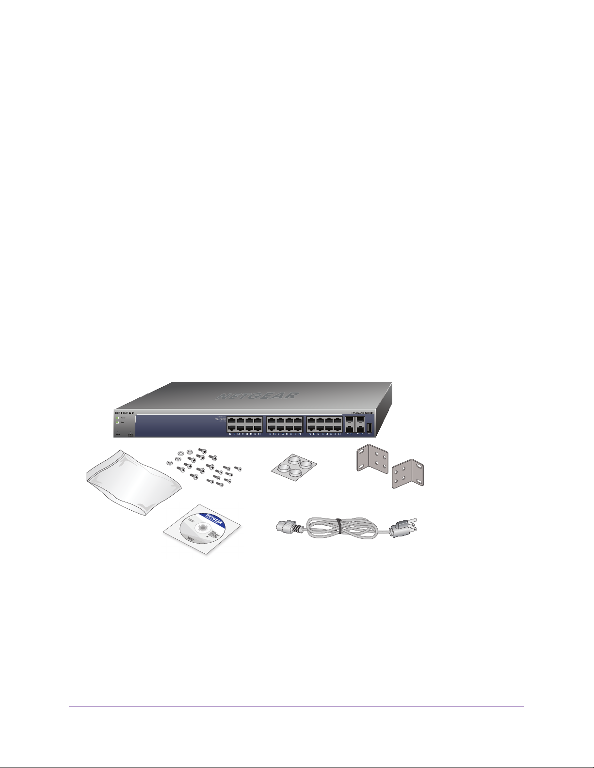
The following figure shows the package contents of the smart managed switch.
Figure 1. Package contents
Verify that the package contains the following:
• XS728T Smart Managed Switch
• Rubber footpads for tabletop installation
• Rack-mounting kit
• Power cord
Introduction
7
Page 8

XS728T Smart Managed Switch
• Installation guide
• Smart managed switch resource CD with NETGEAR Smart Control Center and user’s
manual
If any item is missing or damaged, contact the place of purchase immediately.
Introduction
8
Page 9

2. Physical Description
This chapter describes the XS728T Smart Managed Switch hardware features. This chapter
includes the following topics:
• Front Panel and Back Panel Configuration
• LED Designations
• Device Hardware Interfaces
2
9
Page 10

XS728T Smart Managed Switch
Front Panel and Back Panel Configuration
The smart managed switch provides 24 1000M/10G copper ports and 4
dedicated1000M/10G SFP+ fiber ports. Each port is capable of sensing the line speed and
negotiating the duplex mode with the link partner automatically.
The following figure illustrates the front panel of the smart managed switch.
Power and
Fan LEDs
Factory
Defaults button
Reset button
Figure 2. Front panel
Link/Speed/ACT LEDs
1000M/10G Ethernet ports
1000M/10G
SFP+ ports
USB port
The front panel contains the following:
• T
wenty-four RJ-45 connectors for 1000M/10G AutoSensing 10-Gigabit Ethernet
switching ports
• Four dedicated 1000M/10G SFP+ 10-Gigabit Ethernet switching ports
• One USB 2.0 port that supports F
AT32 file systems
• Reset button to restart the device
• Recessed Factory Defaults button to restore the device back to the factory defaults
• Link, Speed, and
ACT LEDs for each port
• Power and Fan LEDs
The following figure illustrates the smart managed switch back panel.
Kensington Lock™ slot
Figure 3. Back panel
The back panel contains the power connector and the Kensington Lock slot.
Note: The serial console port is not for customer use.
Physical Description
10
Power connector
Page 11

XS728T Smart Managed Switch
LED Designations
The following sections describe the LED designations.
Port LEDs
The following table describes the RJ-45 and SFP+ port LED designations. A separate
indicator LED is associated with each port.
Table 1. Port LEDs
LED Designation
Link/Speed/ACT LED mode for
copper ports 1 to 24
Link/ACT LED for SFP+ ports
25 to 28
• Off. No link established.
• Solid green. A valid 10G link is established.
• Blinking green. The port is transmitting or receiving packets at
10 Gbps.
• Solid yellow . A valid 1000M link is established.
• Blinking yellow. The port is transmitting or receiving packets
at 1000 Mbps.
• Off . No SFP+ module link is established.
• Solid green . A valid 10G link is established.
• Blinking green. The port is transmitting or receiving packets
at 10 Gbps.
• Solid yellow . A valid 1000M link is established.
• Blinking yellow . The port is transmitting or receiving packets at
1000 Mbps.
System LEDs
The following table describes the system LED designations.
Table 2. System LEDs
LED Designation
Power • Solid green . The device is powered on. Runtime code is operating.
• Solid yellow . The device is booting.
• Off . Power is not supplied to the device.
Fan • Solid yellow . The fan experienced a failure.
• Off . The fan is operating normally.
Device Hardware Interfaces
The following sections describe the hardware interfaces on the device.
Physical Description
11
Page 12

XS728T Smart Managed Switch
RJ-45 Ports
RJ-45 ports are AutoSensing ports. When you insert a cable into an RJ-45 port, the switch
automatically determines the maximum speed (1000 Mbps or 10
Gbps) and duplex mode
(half duplex or full duplex) of the attached device. All ports support only an unshielded
twisted-pair (UTP) cable terminated with an 8-pin RJ-45 plug.
To simplify the procedure for attaching devices, all RJ-45 ports support Auto Uplink. This
technology allows attaching devices to the RJ-45 ports with either straight-through or
crossover cables. When you insert a cable into the switch’s RJ-45 port, the switch
automatically does the following:
• Senses whether the cable is a straight-through or crossover cable.
• Determines whether the link to the attached device requires a “normal” connection (such
as when you are connecting the port to a computer) or an uplink connection (such as
when you are connecting the port to a router, switch, or hub).
• Automatically configures the RJ-45 port to enable communications with the attached
device. The Auto Uplink technology compensates for setting uplink connections while
eliminating concerns about whether to use crossover or straight-through cables when you
attach devices.
SFP+ Ports
To enable you to use fiber connections on your network, four dedicated SFP+ ports (25
though 28) accommodate standard 1000M and 10G SFP+ transceiver modules, which are
sold separately.
Reset Button
The Smart Managed Switch provides a Reset button on the front panel to allow you to
manually reboot the switch. This action is equivalent to powering the unit off and back on.
The last saved configuration is loaded into the switch as it resets. To use the Reset button,
insert a device such as a straightened paper clip into the opening to press the recessed
button. The front panel LEDs turn off and light again as the switch performs its power-on
self-test (POST).
Factory Defaults Button
The Smart Managed Switch provides a Factory Defaults button on the front panel so that
you can remove the current configuration and return the device to its factory settings. When
you press the Factory Defaults button, all settings including the password, VLAN settings,
and port configurations are removed. To use the Factory Defaults button, insert a device
such as a straightened paper clip into the opening to press and hold the recessed button for
more than two seconds.
Physical Description
12
Page 13

3. Applications
Your XS728T Smart Managed Switch is designed to provide flexibility in configuring your
network connections. It can be used as your only network traffic-distribution device or with
1000M and 10G hubs and switches. This chapter includes the following topics:
• Desktop Switching
• Backbone Switching
3
13
Page 14

XS728T Smart Managed Switch
Desktop Switching
The smart managed switch can be used as a desktop switch to build a small network that
provides up to 10 Gbps access to a file server. With full duplex enabled, the switch port
connected to the server or computer can provide up to 20 Gbps throughput. If a 10 Gbps
module is used to connect the switch to the file server in full-duplex operation, then the switch
can provide up to 20 Gbps throughput.
Figure 4. Desktop switching
` ` `
Applications
14
Page 15

XS728T Smart Managed Switch
Backbone Switching
You can use the smart managed switch as a backbone switch in a small network that gives
users high-speed access to servers and other network devices.
XS728T
GS108T
` `
Figure 5. Backbone switching
S3300-28x-PoE+
```
Applications
15
Page 16

4. Installation
This chapter describes the installation procedures for your XS728T Smart Managed Switch.
Switch installation involves the steps described in the following sections:
Step 1: Prepare the Site
Step 2: Install the Switch
Step 3: Check the Installation
Step 4: Connect Devices to the Switch
Step 5: Install an SFP+ Transceiver Module
Step 6: Apply AC Power
Step 7: Manage the Switch
4
16
Page 17

XS728T Smart Managed Switch
Step 1: Prepare the Site
Before you install the switch, ensure that the operating environment meets the site
requirements in the following table.
Table 3. Site requirements
Characteristics Requirements
Mounting • Desktop installations. Provide a flat table or shelf surface.
• Rack-mount installations. Use a 19-inch (48.3-centimeter) EIA standard equipment
rack that is grounded and physically secure.
is also required.
Access Place the switch in a position that allows you to access the front panel RJ-45 ports, view the
front panel LEDs, and access the power connector
Power source Provide a power connection cord. Power specifications for the switch are shown in Appendix
B, Technical Specifications. Ensure that the AC outlet is not controlled by a wall switch, which
can accidentally turn off power to the outlet and the switch.
The rack-mount kit supplied with the switch
.
Environmental • T
emperature. Install the switch in a dry area, with ambient temperature between 0ºC
and 50ºC (32ºF and 122ºF). Keep the switch away from heat sources such as direct
sunlight, warm air exhausts, hot-air vents, and heaters.
• Operating humidity.
noncondensing.
• V
entilation. Do not restrict airflow by covering or obstructing air inlets on the sides of the
switch. Keep at least 2 inches (5.08 centimeters) free on all sides for cooling. Be sure
that the room or wiring closet where the switch is installed provides adequate airflow.
• Operating conditions. Keep the switch at least 6 feet (1.83 meters) away from nearest
source of electromagnetic noise, such as a photocopy machine.
The maximum relative humidity of the installation location is 90%,
Step 2: Install the Switch
The smart managed switch can be used on a flat surface or mounted in a standard network
equipment rack.
Install the Switch on a Flat Surface
The switch ships with four self-adhesive rubber footpads. The rubber footpads cushion the
switch against shock and vibrations.
This procedure explains how to install the switch on a flat surface.
To install the switch on a flat surface:
1. Stick one of the provided rubber footpads on each of the four concave spaces on the
bottom of the switch.
2. Place the switch on a flat surface.
Installation
17
Page 18

XS728T Smart Managed Switch
Install the Switch in a Rack
To install the switch in a rack, you need the 19-inch rack-mount kit supplied with the switch.
To install the switch in a rack:
1. Attach the supplied mounting brackets to the side of the switch.
2. Insert the screws provided in the rack-mount kit through each bracket and into the bracket
mounting holes in the switch.
3. T
ighten the screws with a No. 1 Phillips screwdriver to secure each bracket.
4. Align the mounting holes in the brackets with the holes in the rack, and insert two pan-head
screws with nylon washers through each bracket and into the rack.
5. T
ighten the screws with a No. 2 Phillips screwdriver to secure mounting brackets to the rack.
Figure 6. Rack mount
Step 3: Check the Installation
Perform the steps in this section before applying power to the switch.
To check the installation:
1. Inspect the equipment thoroughly
2. V
erify that all cables are installed correctly.
3. Check cable routing to make sure that cables are not damaged or creating a safety hazard.
4. Ensure that all equipment is mounted properly and securely
.
.
Step 4: Connect Devices to the Switch
The following procedure describes how to connect computers to the switch’s RJ-45 ports.
The smart managed switch contains Auto Uplink technology, which allows the attaching of
devices using either straight-through or crossover cables.
Installation
18
Page 19

XS728T Smart Managed Switch
Figure 7. Connecting devices to the switch
Note: Ethernet specifications limit the cable length between the switch and
the attached device to 328 feet (100 meters).
To connect devices to the switch:
Using a Category 5 (CAT 5) unshielded twisted-pair (UTP) cable terminated with an
RJ-45 connector
, connect each computer to an RJ-45 network port on the switch front
panel.
See the previous figure.
Note: For 10GBASE-T connections, and in particular for connections over
100 feet (30 meters), NETGEAR recommends that you use a
Category 6a cable or a higher-rated cable.
Step 5: Install an SFP+ Transceiver Module
The following procedure describes how to install an optional SFP+ or SFP transceiver
module into one of the SFP+ ports of the switch.
Note: Contact your NETGEAR sales office to buy these modules. If you do
not want to install an SFP+ or SFP module, skip this procedure.
To install an SFP+ or SFP transceiver:
1. Insert the transceiver into the SFP+ port.
Installation
19
Page 20

XS728T Smart Managed Switch
2. Press firmly on the flange of the module to seat it securely into the connector.
You can install up to four 10G or 1G Ethernet modules using this procedure.
Figure 8. Installing an SFP transceiver module
Step 6: Apply AC Power
The smart managed switch does not provide an on/off switch. Power is controlled by the
power cord connection.
Before connecting the power cord, select an AC outlet that is not controlled by a wall switch,
which can turn off power to the switch.
To apply AC power:
1. Connect the end of the power connection cable to the power receptacle on the back of
the switch.
2. Plug the
strip.
When you apply power, the Power LED on the switch’s front panel lights.
If the Power LED does not light, check to make sure that the power cable is plugged in
correctly and that the power source is functioning. If this does not resolve the problem, see
Appendix A, Troubleshooting.
AC power connection cable into a power source such as a wall socket or power
Step 7: Manage the Switch
The smart managed switch contains software for viewing, changing, and monitoring the way
it works. This management software is not required for the switch to work. You can use the
ports without using the management software. However, the management software enables
the setup of VLAN and trunking features and also improves the efficiency of the switch, which
improves its overall performance as well as the performance of the network.
Installation
20
Page 21

XS728T Smart Managed Switch
After you power up the switch for the first time, you can configure the smart managed switch
using a web browser or the included Smart Control Center program (requires a Windows
computer). For more information about managing the switch, see the software administration
manual on the smart managed switch resource CD.
Note: The switch is configured with a default IP address of 192.168.0.239
and a subnet mask of 255.255.255.0.
Installation
21
Page 22

A. Troubleshooting
This appendix provides information about troubleshooting the NETGEAR Smart Managed
Switch. The appendix includes the following topics:
• Troubleshooting Chart
• Additional Troubleshooting Suggestions
A
22
Page 23

XS728T Smart Managed Switch
Troubleshooting Chart
The following table lists symptoms, causes, and solutions to possible problems.
Table 4. Troubleshooting chart
Symptom Cause Solution
Power LED is off. No power is received. Check the power cord connections and the connected
device. Ensure that all cables used are correct and
comply with Ethernet specifications.
Link LED is off or
blinking.
File transfer is slow, or
performance degradation
is a problem.
A segment or device is
not recognized as part of
the network.
ACT LED is blinking
continuously on all
connected ports, and the
network is disabled.
Port connection is not
working.
Half-duplex or full-duplex
setting on the switch and
the connected device are
not the same.
One or more devices are
not properly connected,
or cabling does not meet
Ethernet guidelines.
A network loop
(redundant path) was
created.
Check the crimp on the connectors and make sure that
the plug is properly inserted and locked into the port at
both the switch and the connecting device. Ensure that
all cables used are correct and comply with Ethernet
specifications. Check for a defective computer adapter
card, cable, or port by testing them in an alternate
environment where all products are functioning.
Make sure that the attached device is set to
autonegotiate.
Verify that the cabling is correct. Ensure that all
connectors are securely positioned in the required
ports. It is possible that equipment was accidentally
disconnected.
Break the loop by ensuring that only one path exists
from any networked device to any other networked
device.
interface, you can configure the Spanning Tree
Protocol (STP) to prevent network loops.
After you connect to the switch management
Additional Troubleshooting Suggestions
If the suggestions in the troubleshooting chart do not resolve the problem, see the
troubleshooting suggestions in this section.
Network Adapter Cards
Ensure that the network adapter cards installed in the computers are in working condition
and the software driver was installed.
Configuration
If problems occur after you alter the network configuration, restore the original connections
and determine the problem by implementing the new changes, one step at a time. Ensure
Troubleshooting
23
Page 24

XS728T Smart Managed Switch
that cable distances, repeater limits, and other physical aspects of the installation do not
exceed the Ethernet limitations.
Switch Integrity
If necessary, verify the integrity of the switch by resetting the switch. To reset the switch,
remove the AC power from the switch and then reapply AC power. If the problem continues,
contact NETGEAR technical support. In North America, call 1-888-NETGEAR. If you are
outside North America, refer to the support information card included with your product.
Autonegotiation
The RJ-45 ports negotiate the correct duplex mode, speed, and flow control if the device at
the other end of the link supports autonegotiation. If the device does not support
autonegotiation, the switch determines only the speed correctly, and the duplex mode
defaults to half-duplex.
Troubleshooting
24
Page 25

B. Technical Specifications
This appendix lists the specifications for the NETGEAR Smart Managed Switch. The appendix
includes the following topics:
• Network Protocol and Standards Compatibility
• Management
• Interface
• LEDs
• Performance Specifications
• Power Supply
• Physical Specifications
• Environmental Specifications
• Electromagnetic Emissions
• Safety
B
25
Page 26

XS728T Smart Managed Switch
Network Protocol and Standards Compatibility
• IEEE 802.3ab 1000BASE-T
• IEEE 802.3z 1000BASE-X
• IEEE 802.3an (10GBASE-T)
• IEEE 802.3 Clause 49 (10GBASE-LR and 10GBASE-SR)
• IEEE802.3ae (10GBASE Ethernet)
• IEEE 802.3x full-duplex flow control
• IEEE802.3az (Energy Efficient Ethernet)
Management
• MS Windows 7, 8, 8.1; MAC OS X version 10.10
• Web browser:
- MS Internet Explorer 9–11
- Mozilla Firefox 31–33
- Chrome 38–40
- Safari on Windows: 5.1.7
- Safari on MAC: 8.0.2
• IEEE 802.1Q VLAN
• IEEE 802.3ad link aggregation
• IEEE 802.1D Spanning Tree Protocol
• IEEE 802.1w Rapid Spanning Tree Protocol
• IEEE 802.3s MSTP
• IEEE 802.1X port security; dynamic VLAN assignment
• IEEE 802.1AB LLDP, LLDP-MED
• SNMP v1, v2c, and v3
• TFTP, HTTP, and HTTPS
• Port mirroring (RX, TX, and both)
• IGMP snooping v1/v2/v3
• IEEE 802.1p Class of Service (CoS)
• SNTP (Simple Network Time Protocol) 3 servers (disabled by default)
• Jumbo frame support (10K)
• IPv6 management, multicast, and QoS
• Static routing
• MLD snooping
• DHCP snooping
Technical Specifications
26
Page 27

XS728T Smart Managed Switch
• Protocol and MAC-based VLAN
• ACLs (MAC-based, IPv4-based, IPv6-based, and TCP/UDP-based)
• Private VLAN
• DNS
• TACACS+
• Protected ports
• Syslog
• USB
• GVRP
• Cable test
• Ping and traceroute
Interface
• 24 RJ-45 connectors for 1000BASE-T and 10GBASE-T (Auto Uplink™ on all ports)
• Four 10 Gbps dedicated SFP+ slots (ports 25–28) to support 10 Gbps (SPF+) or 1 Gbps
(SFP) optical module.
LEDs
• Per RJ-45 port: Speed/Link/ACT
• Per SFP+ port: Speed/Link/ACT
• Per device: Power, Fan
Performance Specifications
• Forwarding modes: Store-and-forward
• Address database size: 16K Media Access Control (MAC) addresses per system
• Mean time between failure (MTBF): 514,977 hours (~58.8 years) at 25°C
Power Supply
100 VAC–240 VAC/50 Hz–60 Hz, 3.0A maximum, universal input
Physical Specifications
• Dimensions (H x W x D): 43 mm x 440 mm x 310mm (1.7 in. x 17.3 in. x 12.2 in.)
Technical Specifications
27
Page 28

XS728T Smart Managed Switch
• Weight: 5.04 kg (11.11 lb)
Environmental Specifications
• Operating temperature: 0°C to 50°C (32°F to 122°F)
• Operating humidity: 10% to 90% maximum relative humidity, noncondensing
• Storage temperature: –20°C to 70°C (–4°F to 158°F)
• Storage humidity: 5% to 95% maximum relative humidity, noncondensing
Electromagnetic Emissions
• CE Class A, including EN 55022 (CISPR 22), EN 55024, and EN 50082-1
• FCC Part 15 Class A
• VCCI Class A
• C-Tick
Safety
• UL/cUL
• CE EN 60950-1
• CB
• CCC
Technical Specifications
28
 Loading...