

Page 1

XS712T Smart Switch
Software Administration Manual
350 East Plumeria Drive
San Jose, CA 95134
USA
March 2013
202-11254-02
v2.0
Page 2

XS712T Smart Switch
® NETGEAR, Inc. All rights reserved
No part of this publication may be reproduced, transmitted, transcribed, stored in a retrieval system, or translated
into any language in any form or by any means without the written permission of NETGEAR, Inc.
Techn ical Su pport
Thank you for choosing NETGEAR. To register your product, get the latest product updates, get support online, or
for more information about the topics covered in this manual, visit the support website at
http://support.netgear.com.
Phone (US & Canada only): 1-888-NETGEAR
Phone (Other Countries): Check the li
http://support.netgear.com/app/answers/detail/a_id/984.
st of phone numbers at
Trademarks
NETGEAR, the NETGEAR logo, ReadyNAS, ProSafe, ProSecure, Smart Control Center, Auto Uplink, X-RAID2,
and NeoTV are trademarks or registered trademarks of NETGEAR, Inc. Microsoft, Windows, Windows NT, and
Vista are registered trademarks of Microsoft Corporation. Other brand and product names are registered
trademarks or trademarks of their respective holders.
Statement of Conditions
To improve internal design, operational function, and/or reliability, NETGEAR reserves the right to make changes
to the products described in this document without notice. NETGEAR does not assume any liability that may occur
due to the use, or application of, the product(s) or circuit layout(s) described herein.
Revision History
Publication Part Number Version Publish Date Comments
202-11254-02 v2.0 April 2013 Minor text edits.
202-11254-01 v1.0 March 2013 First publication
2
Page 3

Contents
Chapter 1 Getting Started
Chapter 2 Configure System Information
Getting Started with the XS712T Smart Switch . . . . . . . . . . . . . . . . . . . . . . 7
Connect the Switch to the Network . . . . . . . . . . . . . . . . . . . . . . . . . . . . . . . 8
Discover a Switch in a Network with a DHCP Server . . . . . . . . . . . . . . . . . 9
Discover a Switch in a Network without a DHCP Server . . . . . . . . . . . . . . 10
Configure the Network Settings on the Administrative System . . . . . . . . . 12
Access the Management Interface from a Web Browser . . . . . . . . . . . . . 15
Understand the User Interfaces. . . . . . . . . . . . . . . . . . . . . . . . . . . . . . . . . 16
Use the Web Interface . . . . . . . . . . . . . . . . . . . . . . . . . . . . . . . . . . . . . . 16
Use SNMPv3 . . . . . . . . . . . . . . . . . . . . . . . . . . . . . . . . . . . . . . . . . . . . . 21
Support . . . . . . . . . . . . . . . . . . . . . . . . . . . . . . . . . . . . . . . . . . . . . . . . . 24
User Guide. . . . . . . . . . . . . . . . . . . . . . . . . . . . . . . . . . . . . . . . . . . . . . . 24
Management . . . . . . . . . . . . . . . . . . . . . . . . . . . . . . . . . . . . . . . . . . . . . . . 26
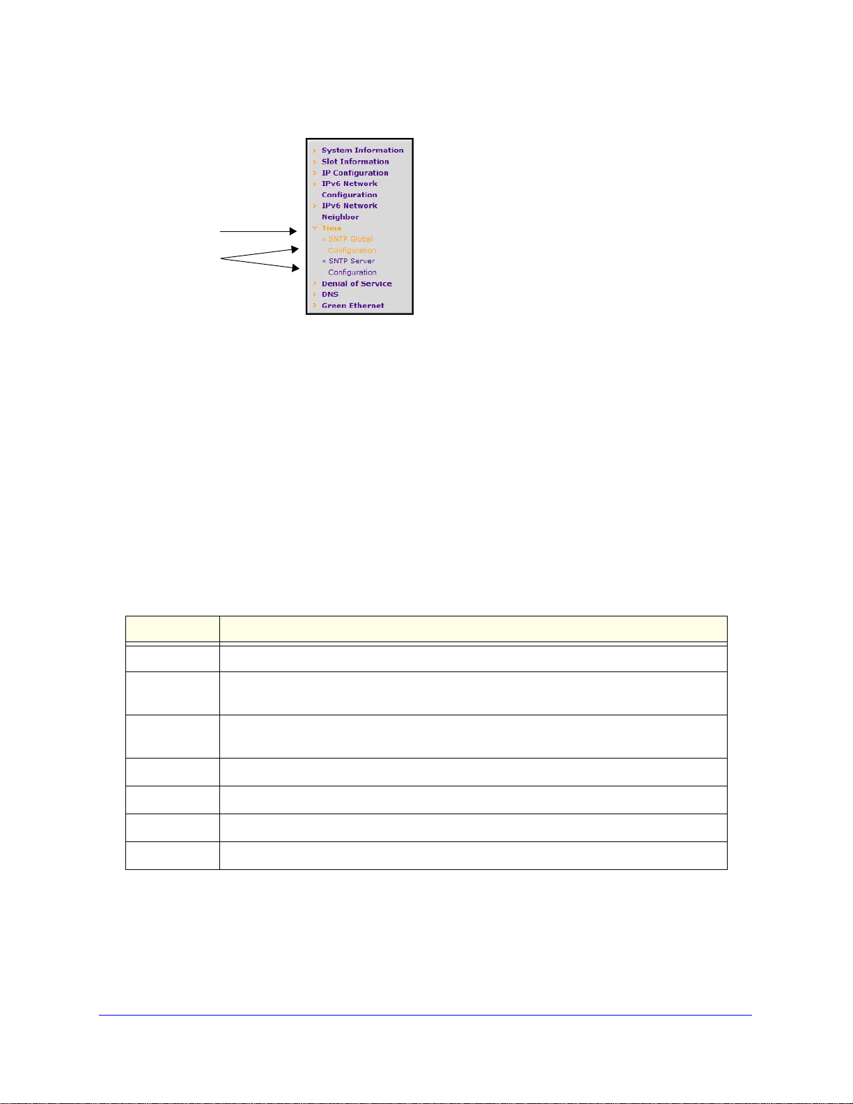
IPv6 Network Neighbor . . . . . . . . . . . . . . . . . . . . . . . . . . . . . . . . . . . . . 32
Time. . . . . . . . . . . . . . . . . . . . . . . . . . . . . . . . . . . . . . . . . . . . . . . . . . . . 33
Denial of Service . . . . . . . . . . . . . . . . . . . . . . . . . . . . . . . . . . . . . . . . . . 40
Green Ethernet . . . . . . . . . . . . . . . . . . . . . . . . . . . . . . . . . . . . . . . . . . . 46
SNMPV1/V2. . . . . . . . . . . . . . . . . . . . . . . . . . . . . . . . . . . . . . . . . . . . . . 53
LLDP-MED Network Policy . . . . . . . . . . . . . . . . . . . . . . . . . . . . . . . . . . 60
LLDP-MED Port Settings . . . . . . . . . . . . . . . . . . . . . . . . . . . . . . . . . . . . 61
Local Information . . . . . . . . . . . . . . . . . . . . . . . . . . . . . . . . . . . . . . . . . . 62
Neighbors Information . . . . . . . . . . . . . . . . . . . . . . . . . . . . . . . . . . . . . . 65
Services—DHCP Snooping. . . . . . . . . . . . . . . . . . . . . . . . . . . . . . . . . . . . 69
Chapter 3 Layer 2 Switching Configuration
Ports . . . . . . . . . . . . . . . . . . . . . . . . . . . . . . . . . . . . . . . . . . . . . . . . . . . . . 77
Port Configuration . . . . . . . . . . . . . . . . . . . . . . . . . . . . . . . . . . . . . . . . . 77
Flow Control. . . . . . . . . . . . . . . . . . . . . . . . . . . . . . . . . . . . . . . . . . . . . . 79
LAG Configuration . . . . . . . . . . . . . . . . . . . . . . . . . . . . . . . . . . . . . . . . . 80
LAG Membership. . . . . . . . . . . . . . . . . . . . . . . . . . . . . . . . . . . . . . . . . . 81
LACP Configuration. . . . . . . . . . . . . . . . . . . . . . . . . . . . . . . . . . . . . . . . 82
VLANs . . . . . . . . . . . . . . . . . . . . . . . . . . . . . . . . . . . . . . . . . . . . . . . . . . . . 84
VLAN Membership Configuration . . . . . . . . . . . . . . . . . . . . . . . . . . . . . 86
VLAN Status . . . . . . . . . . . . . . . . . . . . . . . . . . . . . . . . . . . . . . . . . . . . . 87
Port VLAN ID Configuration. . . . . . . . . . . . . . . . . . . . . . . . . . . . . . . . . . 87
MAC Based VLAN . . . . . . . . . . . . . . . . . . . . . . . . . . . . . . . . . . . . . . . . . 89
Table of Contents | 3
Page 4

XS712T Smart Switch
Protocol Based VLAN Group Configuration . . . . . . . . . . . . . . . . . . . . . . 90
Protocol Based VLAN Group Membership. . . . . . . . . . . . . . . . . . . . . . . 91
Auto-VoIP Configuration. . . . . . . . . . . . . . . . . . . . . . . . . . . . . . . . . . . . . . .93
Configure Protocol-Based Auto VoIP Settings . . . . . . . . . . . . . . . . . . . . 93
Port Settings. . . . . . . . . . . . . . . . . . . . . . . . . . . . . . . . . . . . . . . . . . . . . . 95
OUI Table . . . . . . . . . . . . . . . . . . . . . . . . . . . . . . . . . . . . . . . . . . . . . . . . 96
CST Port Configuration . . . . . . . . . . . . . . . . . . . . . . . . . . . . . . . . . . . . 102
Rapid STP . . . . . . . . . . . . . . . . . . . . . . . . . . . . . . . . . . . . . . . . . . . . . . 105
MST Configuration . . . . . . . . . . . . . . . . . . . . . . . . . . . . . . . . . . . . . . . . 106
MST Port Configuration . . . . . . . . . . . . . . . . . . . . . . . . . . . . . . . . . . . . 107
STP Statistics . . . . . . . . . . . . . . . . . . . . . . . . . . . . . . . . . . . . . . . . . . . . 109
Bridge Multicast Forwarding. . . . . . . . . . . . . . . . . . . . . . . . . . . . . . . . . 111
MFDB Table . . . . . . . . . . . . . . . . . . . . . . . . . . . . . . . . . . . . . . . . . . . . . 112
IGMP Snooping . . . . . . . . . . . . . . . . . . . . . . . . . . . . . . . . . . . . . . . . . . 114
IGMP Snooping Querier . . . . . . . . . . . . . . . . . . . . . . . . . . . . . . . . . . . . 121
MLD Snooping . . . . . . . . . . . . . . . . . . . . . . . . . . . . . . . . . . . . . . . . . . . 124
Forwarding Database . . . . . . . . . . . . . . . . . . . . . . . . . . . . . . . . . . . . . . . . 132
MAC Address Table . . . . . . . . . . . . . . . . . . . . . . . . . . . . . . . . . . . . . . . 132
Dynamic Address Configuration. . . . . . . . . . . . . . . . . . . . . . . . . . . . . . 133
Address Table . . . . . . . . . . . . . . . . . . . . . . . . . . . . . . . . . . . . . . . . . . . 134
Static MAC Address . . . . . . . . . . . . . . . . . . . . . . . . . . . . . . . . . . . . . . . 135
Chapter 4 Configuring Routing
Configure IP Settings . . . . . . . . . . . . . . . . . . . . . . . . . . . . . . . . . . . . . . . . 137
IP Statistics. . . . . . . . . . . . . . . . . . . . . . . . . . . . . . . . . . . . . . . . . . . . . . 138
Configure VLAN Routing . . . . . . . . . . . . . . . . . . . . . . . . . . . . . . . . . . . . . 142
VLAN Routing Wizard. . . . . . . . . . . . . . . . . . . . . . . . . . . . . . . . . . . . . . 142
Router Discovery Configuration . . . . . . . . . . . . . . . . . . . . . . . . . . . . . . 145
Configure and View Routes . . . . . . . . . . . . . . . . . . . . . . . . . . . . . . . . . . . 146
Configure ARP . . . . . . . . . . . . . . . . . . . . . . . . . . . . . . . . . . . . . . . . . . . . . 148
ARP Cache. . . . . . . . . . . . . . . . . . . . . . . . . . . . . . . . . . . . . . . . . . . . . . 148
Create a Static ARP Entry . . . . . . . . . . . . . . . . . . . . . . . . . . . . . . . . . . 149
Configure Global ARP Settings . . . . . . . . . . . . . . . . . . . . . . . . . . . . . . 150
Chapter 5 Configuring Quality of Service
Class of Service . . . . . . . . . . . . . . . . . . . . . . . . . . . . . . . . . . . . . . . . . . . . 153
Basic CoS Configuration . . . . . . . . . . . . . . . . . . . . . . . . . . . . . . . . . . . 154
CoS Interface Configuration . . . . . . . . . . . . . . . . . . . . . . . . . . . . . . . . . 155
Interface Queue Configuration . . . . . . . . . . . . . . . . . . . . . . . . . . . . . . .156
802.1p to Queue Mapping . . . . . . . . . . . . . . . . . . . . . . . . . . . . . . . . . . 158
DSCP to Queue Mapping. . . . . . . . . . . . . . . . . . . . . . . . . . . . . . . . . . . 159
Differentiated Services . . . . . . . . . . . . . . . . . . . . . . . . . . . . . . . . . . . . . . . 160
Defining DiffServ. . . . . . . . . . . . . . . . . . . . . . . . . . . . . . . . . . . . . . . . . . 160
Class Configuration . . . . . . . . . . . . . . . . . . . . . . . . . . . . . . . . . . . . . . . 162
Policy Configuration . . . . . . . . . . . . . . . . . . . . . . . . . . . . . . . . . . . . . . . 166
Service Configuration . . . . . . . . . . . . . . . . . . . . . . . . . . . . . . . . . . . . . . 169
Service Statistics . . . . . . . . . . . . . . . . . . . . . . . . . . . . . . . . . . . . . . . . . 170
4
Page 5

XS712T Smart Switch
Chapter 6 Managing Device Security
Management Security Settings. . . . . . . . . . . . . . . . . . . . . . . . . . . . . . . . . 171
Change Password . . . . . . . . . . . . . . . . . . . . . . . . . . . . . . . . . . . . . . . .171
Authentication List Configuration . . . . . . . . . . . . . . . . . . . . . . . . . . . . .180
Configure Management Access . . . . . . . . . . . . . . . . . . . . . . . . . . . . . . . .183
HTTP Configuration . . . . . . . . . . . . . . . . . . . . . . . . . . . . . . . . . . . . . . . 183
Secure HTTP Configuration . . . . . . . . . . . . . . . . . . . . . . . . . . . . . . . . . 184
Certificate Management . . . . . . . . . . . . . . . . . . . . . . . . . . . . . . . . . . . . 185
Certificate Download. . . . . . . . . . . . . . . . . . . . . . . . . . . . . . . . . . . . . . .186
802.1X Configuration . . . . . . . . . . . . . . . . . . . . . . . . . . . . . . . . . . . . . . 190
Port Authentication . . . . . . . . . . . . . . . . . . . . . . . . . . . . . . . . . . . . . . . .191
Port Summary. . . . . . . . . . . . . . . . . . . . . . . . . . . . . . . . . . . . . . . . . . . .195
Traffic Control . . . . . . . . . . . . . . . . . . . . . . . . . . . . . . . . . . . . . . . . . . . . . .197
MAC Filter Configuration . . . . . . . . . . . . . . . . . . . . . . . . . . . . . . . . . . .197
MAC Filter Summary . . . . . . . . . . . . . . . . . . . . . . . . . . . . . . . . . . . . . .199
Port Security Configuration. . . . . . . . . . . . . . . . . . . . . . . . . . . . . . . . . .201
Port Security Interface Configuration . . . . . . . . . . . . . . . . . . . . . . . . . . 202
Security MAC Address . . . . . . . . . . . . . . . . . . . . . . . . . . . . . . . . . . . . . 204
Private VLAN Configuration . . . . . . . . . . . . . . . . . . . . . . . . . . . . . . . . .205
Private VLAN Association Configuration . . . . . . . . . . . . . . . . . . . . . . .206
Private VLAN Port Mode Configuration . . . . . . . . . . . . . . . . . . . . . . . .207
Private VLAN Host Interface Configuration . . . . . . . . . . . . . . . . . . . . . 208
Private VLAN Promiscuous Interface Configuration. . . . . . . . . . . . . . . 210
MAC Rules . . . . . . . . . . . . . . . . . . . . . . . . . . . . . . . . . . . . . . . . . . . . . .216
MAC Binding Configuration . . . . . . . . . . . . . . . . . . . . . . . . . . . . . . . . .218
MAC Binding Table. . . . . . . . . . . . . . . . . . . . . . . . . . . . . . . . . . . . . . . .219
IP ACL . . . . . . . . . . . . . . . . . . . . . . . . . . . . . . . . . . . . . . . . . . . . . . . . . 220
IP Rules . . . . . . . . . . . . . . . . . . . . . . . . . . . . . . . . . . . . . . . . . . . . . . . .221
IP Extended Rules . . . . . . . . . . . . . . . . . . . . . . . . . . . . . . . . . . . . . . . . 222
IPv6 ACL. . . . . . . . . . . . . . . . . . . . . . . . . . . . . . . . . . . . . . . . . . . . . . . .225
IPv6 Rules . . . . . . . . . . . . . . . . . . . . . . . . . . . . . . . . . . . . . . . . . . . . . .226
Chapter 7 Monitoring the System
Ports . . . . . . . . . . . . . . . . . . . . . . . . . . . . . . . . . . . . . . . . . . . . . . . . . . . . .233
Switch Statistics . . . . . . . . . . . . . . . . . . . . . . . . . . . . . . . . . . . . . . . . . .233
Port Statistics . . . . . . . . . . . . . . . . . . . . . . . . . . . . . . . . . . . . . . . . . . . .236
Logs . . . . . . . . . . . . . . . . . . . . . . . . . . . . . . . . . . . . . . . . . . . . . . . . . . . . . 248
FLASH Log . . . . . . . . . . . . . . . . . . . . . . . . . . . . . . . . . . . . . . . . . . . . . . 250
Mirroring . . . . . . . . . . . . . . . . . . . . . . . . . . . . . . . . . . . . . . . . . . . . . . . . . . 256
Chapter 8 Maintenance
Reset . . . . . . . . . . . . . . . . . . . . . . . . . . . . . . . . . . . . . . . . . . . . . . . . . . . .259
Device Reboot . . . . . . . . . . . . . . . . . . . . . . . . . . . . . . . . . . . . . . . . . . .259
Factory Default . . . . . . . . . . . . . . . . . . . . . . . . . . . . . . . . . . . . . . . . . . .260
Upload . . . . . . . . . . . . . . . . . . . . . . . . . . . . . . . . . . . . . . . . . . . . . . . . . . .260
HTTP File Upload . . . . . . . . . . . . . . . . . . . . . . . . . . . . . . . . . . . . . . . . . 262
5
Page 6

XS712T Smart Switch
Download . . . . . . . . . . . . . . . . . . . . . . . . . . . . . . . . . . . . . . . . . . . . . . . . . 263
TFTP File Download. . . . . . . . . . . . . . . . . . . . . . . . . . . . . . . . . . . . . . . 263
HTTP File Download . . . . . . . . . . . . . . . . . . . . . . . . . . . . . . . . . . . . . . 265
File Management . . . . . . . . . . . . . . . . . . . . . . . . . . . . . . . . . . . . . . . . . . .266
Copy . . . . . . . . . . . . . . . . . . . . . . . . . . . . . . . . . . . . . . . . . . . . . . . . . . . 266
Dual Image Configuration. . . . . . . . . . . . . . . . . . . . . . . . . . . . . . . . . . . 267
Appendix A Smart Control Center Utilities
Network Utilities . . . . . . . . . . . . . . . . . . . . . . . . . . . . . . . . . . . . . . . . . . . . 269
Upload and Download the Configuration . . . . . . . . . . . . . . . . . . . . . . . 273
Appendix B Troubleshooting
Troubleshooting Configuration Menu . . . . . . . . . . . . . . . . . . . . . . . . . . . . 279
Ping . . . . . . . . . . . . . . . . . . . . . . . . . . . . . . . . . . . . . . . . . . . . . . . . . . . 279
Troubleshooting Chart . . . . . . . . . . . . . . . . . . . . . . . . . . . . . . . . . . . . . . . 283
Appendix C Configuration Examples
Virtual Local Area Networks (VLANs) . . . . . . . . . . . . . . . . . . . . . . . . . . . 285
Sample VLAN Configuration. . . . . . . . . . . . . . . . . . . . . . . . . . . . . . . . . 286
Access Control Lists (ACLs). . . . . . . . . . . . . . . . . . . . . . . . . . . . . . . . . . .287
MAC ACL Example Configuration . . . . . . . . . . . . . . . . . . . . . . . . . . . . 288
Sample Standard IP ACL Configuration. . . . . . . . . . . . . . . . . . . . . . . . 289
Differentiated Services (DiffServ) . . . . . . . . . . . . . . . . . . . . . . . . . . . . . . . 290
DiffServ Traffic Classes . . . . . . . . . . . . . . . . . . . . . . . . . . . . . . . . . . . . 291
Sample DiffServ Configuration . . . . . . . . . . . . . . . . . . . . . . . . . . . . . . . 293
802.1X . . . . . . . . . . . . . . . . . . . . . . . . . . . . . . . . . . . . . . . . . . . . . . . . . . . 294
Sample 802.1X Configuration. . . . . . . . . . . . . . . . . . . . . . . . . . . . . . . . 296
MSTP . . . . . . . . . . . . . . . . . . . . . . . . . . . . . . . . . . . . . . . . . . . . . . . . . . . . 297
VLAN Routing Overview. . . . . . . . . . . . . . . . . . . . . . . . . . . . . . . . . . . . 301
Sample VLAN Routing Configuration . . . . . . . . . . . . . . . . . . . . . . . . . . 301
Appendix D Hardware Specifications and Default Values
XS712T Smart Switch Specifications . . . . . . . . . . . . . . . . . . . . . . . . . . . . 303
XS712T Switch Features and Defaults . . . . . . . . . . . . . . . . . . . . . . . . . . 304
Appendix E Notification of Compliance
6
Page 7

1. Getting Started
This manual describes how to configure and operate the XS712T Smart Switch by using the
web-based graphical user interface (GUI). The manual describes the software configuration
procedures and explains the options available within those procedures.
Note: For information about issues and workarounds, see the release
notes for the XS712T Smart Switch.
Getting Started with the XS712T Smart Switch
This chapter provides an overview of starting your NETGEAR XS712T Smart Switch and
accessing the user interface. It also leads you through the steps to use the Smart Control
Center utility. This chapter contains the following sections:
1
• Switch Management Interface
• Connect the Switch to the Network
• Discover a Switch in a Network with a DHCP Server
• Discover a Switch in a Network without a DHCP Server
• Configure the Network Settings on the Administrative System
• Access the Management Interface from a Web Browser
• Understand the User Interfaces
• Interface Naming Convention
• Online Help
• Registration
7
Page 8

XS712T Smart Switch
Switch Management Interface
The NETGEAR XS712T Smart Switch contain an embedded web server and management
software for managing and monitoring switch functions. The XS712T functions as a simple
switch without the management software. However, you can use the management software
to configure more advanced features that can improve switch efficiency and overall network
performance.
Web-based management lets you monitor, configure, and control your switch remotely using
a standard web browser instead of using expensive and complicated SNMP software
products. From your web browser, you can monitor the performance of your switch and
optimize its configuration for your network. You can configure all switch features, such as
VLANs, QoS, and ACLs, by using the web management interface.
NETGEAR provides the Smart Control Center utility with this product. This program runs
under Microsoft Windows XP, Windows 2000, or Windows Vista and provides a front end that
discovers the switches on your network segment (L2 broadcast domain). When you power up
your switch for the first time, use the Smart Control Center to discover the switch and view
the network information that has been automatically assigned to the switch by a DHCP
server; or, if no DHCP server is present on the network, use the Smart Control Center to
discover the switch and assign static network information.
In addition to enabling NETGEAR switch discovery, the Smart Control Center provides
several utilities to help you maintain the NETGEAR switches on your network, such as
password management, firmware upgrade, and configuration file backup. For more
information, see
Appendix A, Smart Control Center Utilities.
Connect the Switch to the Network
To enable remote management of the switch through a web browser or SNMP, you must
connect the switch to the network and configure it with network information (an IP address,
subnet mask, and default gateway). The switch has a default IP address of 192.168.0.239
and a default subnet mask of 255.255.255.0.
To change the default network information on the switch, use one of the following three
methods:
• Dynamic assignment through DHCP. DHCP is enabled by default on the switch. If you
connect the switch to a network with a DHCP server, the switch obtains its network
information automatically. You can use the Smart Control Center to discover the
automatically assigned network information. For more information, see
in a Network with a DHCP Server on page 9.
• Static assignment through the Smart Control Center. If you connect the switch to a
network that does not have a DHCP server, you can use the Smart Control Center to
assign a static IP address, subnet mask, and default gateway. For more information, see
Discover a Switch in a Network without a DHCP Server on page 10.
• Static assignment by connecting from a local host. If you do not want to use the
Smart Control Center to assign a static address, you can connect to the switch from a
Discover a Switch
8
Page 9
XS712T Smart Switch
host (administrative system) in the 192.168.0.0/24 network and change the settings by
using the web management interface on the switch. For information about how to set the
IP address on the administrative system so it is in the same subnet as the default IP
address of the switch, see Configure the Network Settings on the Administrative System
on page 12.
Discover a Switch in a Network with a DHCP Server
This section describes how to set up your switch in a network that has a DHCP server. The
DHCP client on the switch is enabled by default. When you connect it to your network, the
DHCP server will automatically assign an IP address to your switch. Use the Smart Control
Center to discover the IP address automatically assigned to the switch.
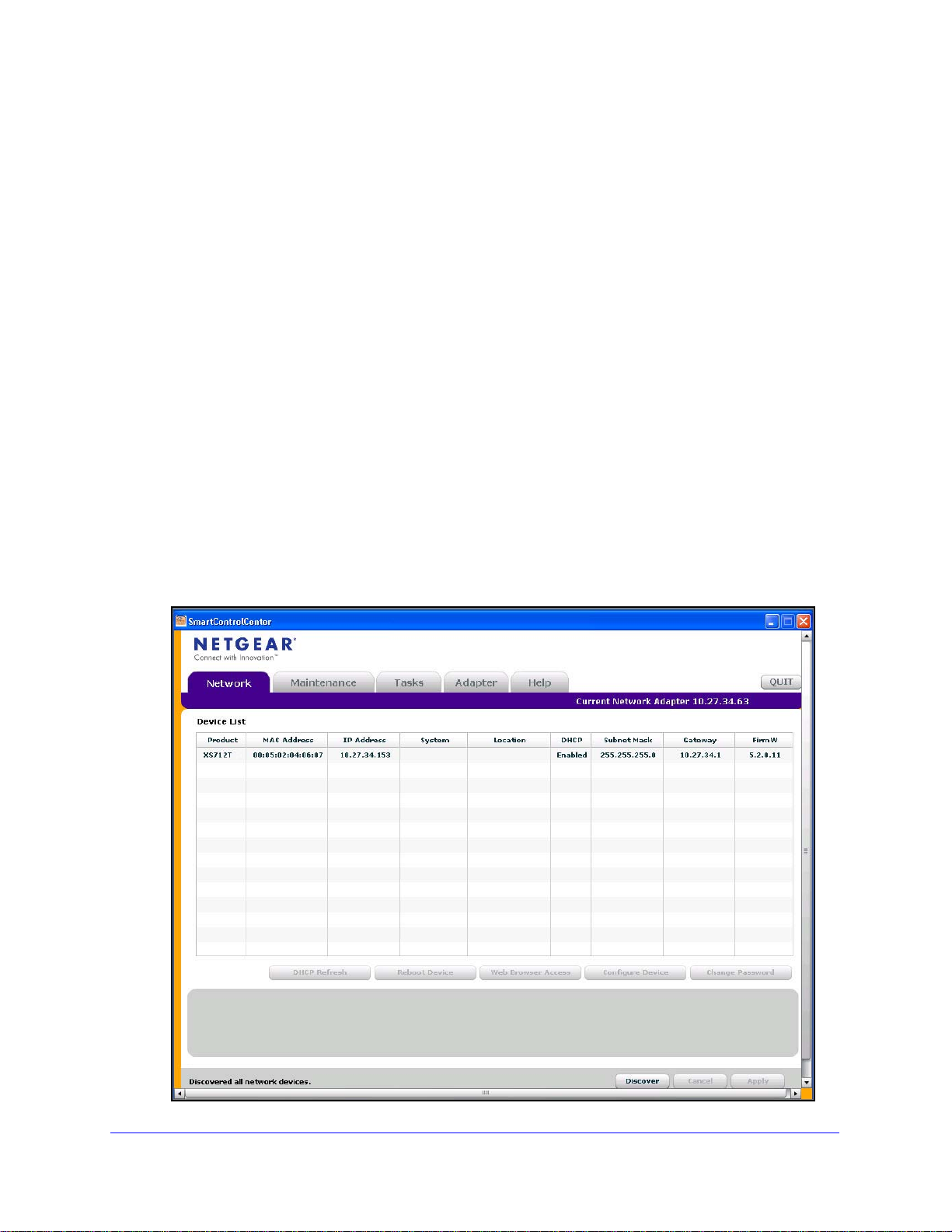
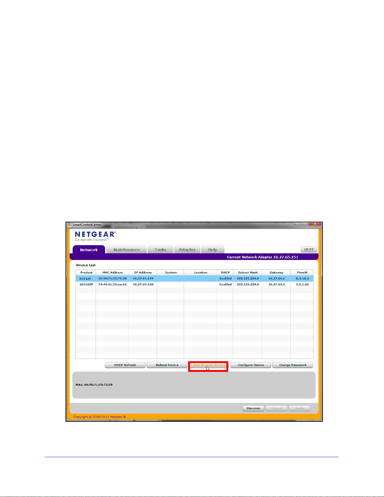
To install the switch in a network with a DHCP server:
1. Con
2. Power on the swit
3. Inst
4. S
5. Click Disc
nect the switch to a network with a DHCP server.
ch by connecting its power cord.
all the Smart Control Center on your computer.
tart the Smart Control Center.
over for the Smart Control Center to find your switch.
A screen similar to the one shown in the following figure displays.
9
Page 10
XS712T Smart Switch
6. Make a note of the displayed IP address assigned by the DHCP server.
You will need this value to access the switch directly fro
m a web browser (without using
the Smart Control Center).
7. Select your switch by clicking the line that displays the switch, then click the
Web Browser Access butt
on.
The Smart Control Center displays a login window.
Use your web browser to manage your switch. The default password is password. Use
this screen to manage your switch. For more information, see Use the Web Interface on
page 16.
Discover a Switch in a Network without a DHCP Server
This section describes how to use the Smart Control Center to set up your switch in a
network without a DHCP server. If your network has no DHCP service, you must assign a
static IP address to your switch. If you choose, you can assign it a static IP address, even if
your network has DHCP service.
To assign a static IP address:
1. Connect the switch
2. Power
3. In
4. S
5. Click Discov
on the switch by connecting its power cord.
stall the Smart Control Center on your computer.
tart the Smart Control Center.
er for the Smart Control Center to find your XS712T switch.
The utility broadcasts Layer 2 discovery packets
the switch.
to your existing network.
within the broadcast domain to discover
10
Page 11

XS712T Smart Switch
6. Select the switch, then click Configure Device.
The screen expands to display additional fields at the bottom.
7. Select the Disabled radio button to disable DHCP.
8. Ente
r the static switch IP address, gateway IP address, and subnet mask for the switch, and
then type your password.
Tip: Y
ou must enter the current password every time you use the Smart
Control Center to update the switch setting. The default password is
password.
9. Click App
ly to configure the switch with the network settings.
Ensure that your computer and the switch are in the same subnet. Make a note of these
settings
for later use.
11
Page 12
XS712T Smart Switch
Configure the Network Settings on the Administrative System
If you choose not to use the Smart Control Center to configure the network information on the
switch, you can connect directly to the switch from an administrative system, such as a
computer or laptop. The IP address of the administrative system must be in the same subnet
as the default IP address on the switch. For most networks, this means you must change the
IP address of the administrative system to be on the same subnet as the default IP address
of the switch (192.168.0.239).
The method to change the IP address on an administra
operating system version. You need Windows Administrator privileges to change these
settings. The following procedures show how to change the static IP address on a computer
running a Microsoft Windows 7.
To modify the network settings on your administrative system:
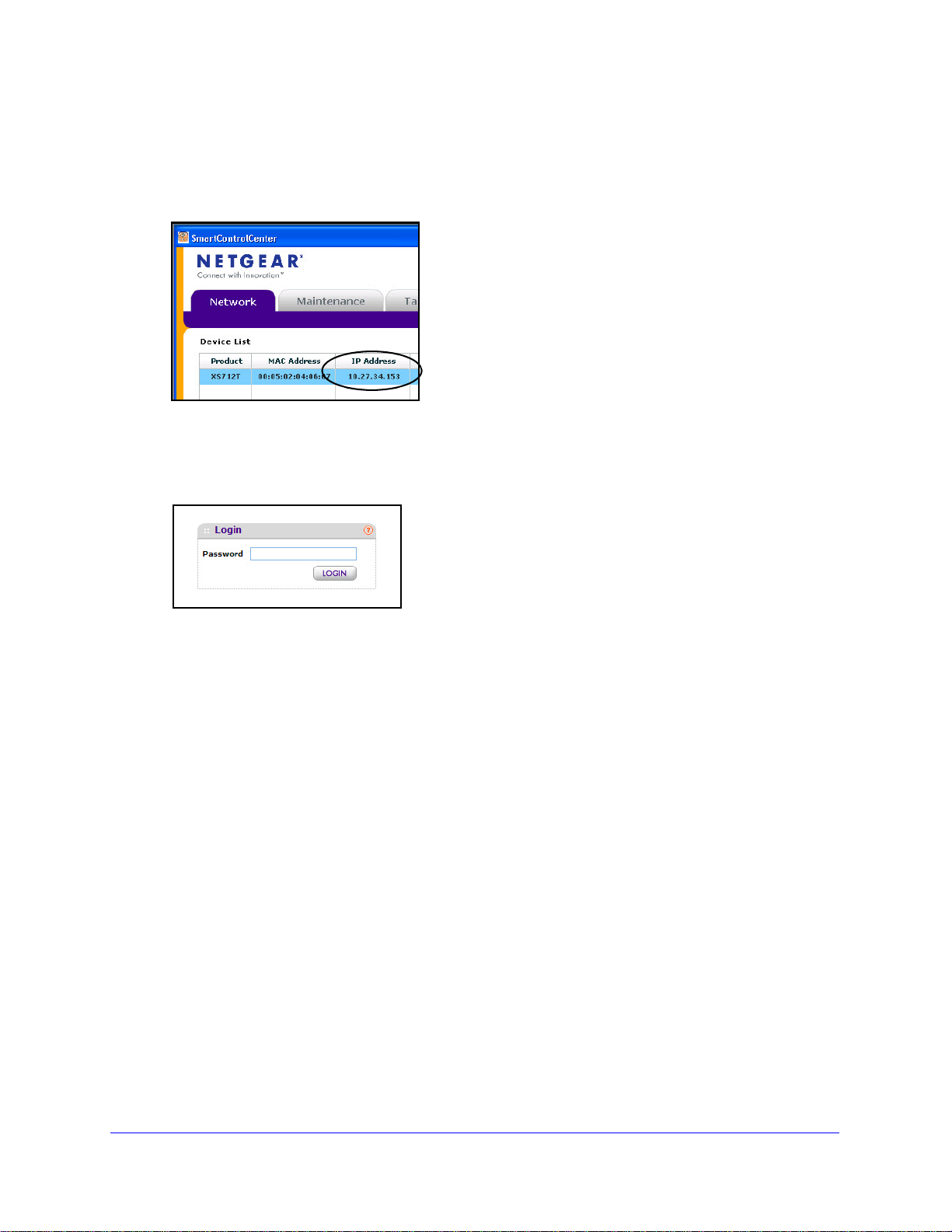
1. Op
2. Click the L
en the Control Panel and click Network and Sharing Center.
ocal Area Connection link.
tive system varies depending on the
12
Page 13
XS712T Smart Switch
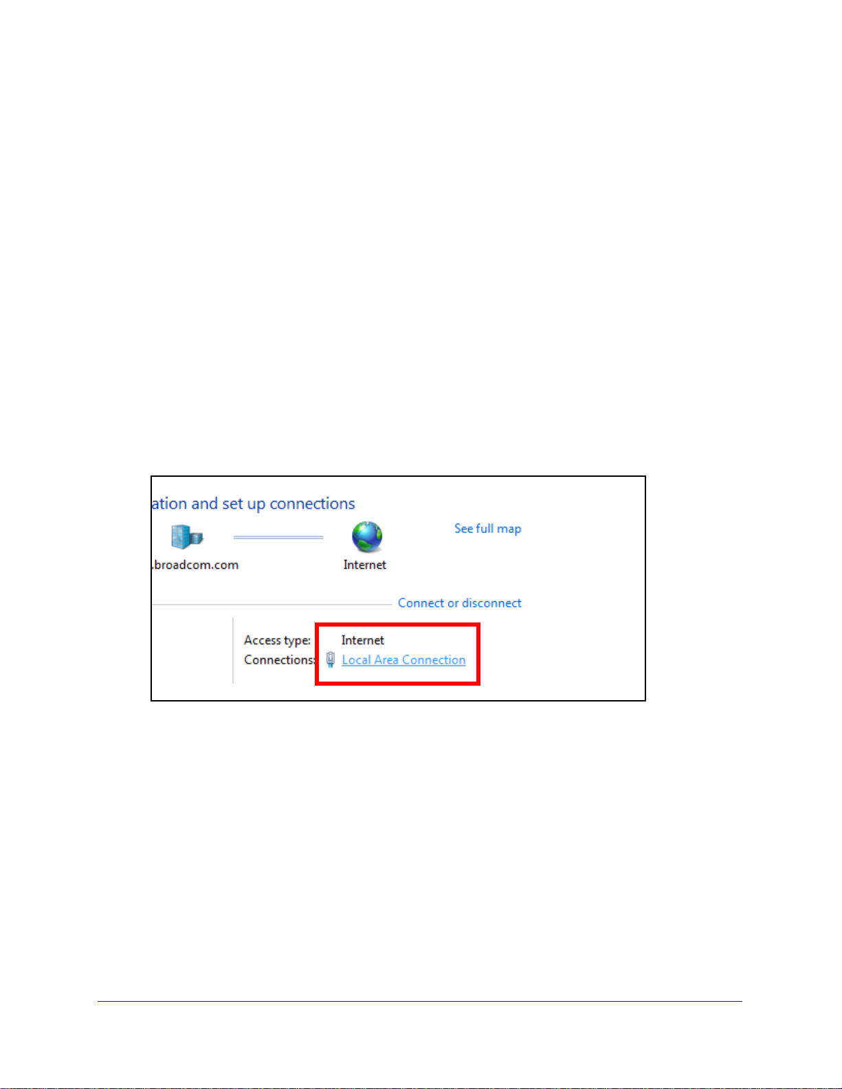
3. In the Local Area Connection Status window, click Properties.
The Local Area Connection Properties window displays.
4. Select the Internet Protocol Version 4 (TCP/IPv4) option, and then click Properties.
The Internet Protocol Version 4 (TCP/IPv4) Propert
13
ies window displays.
Page 14
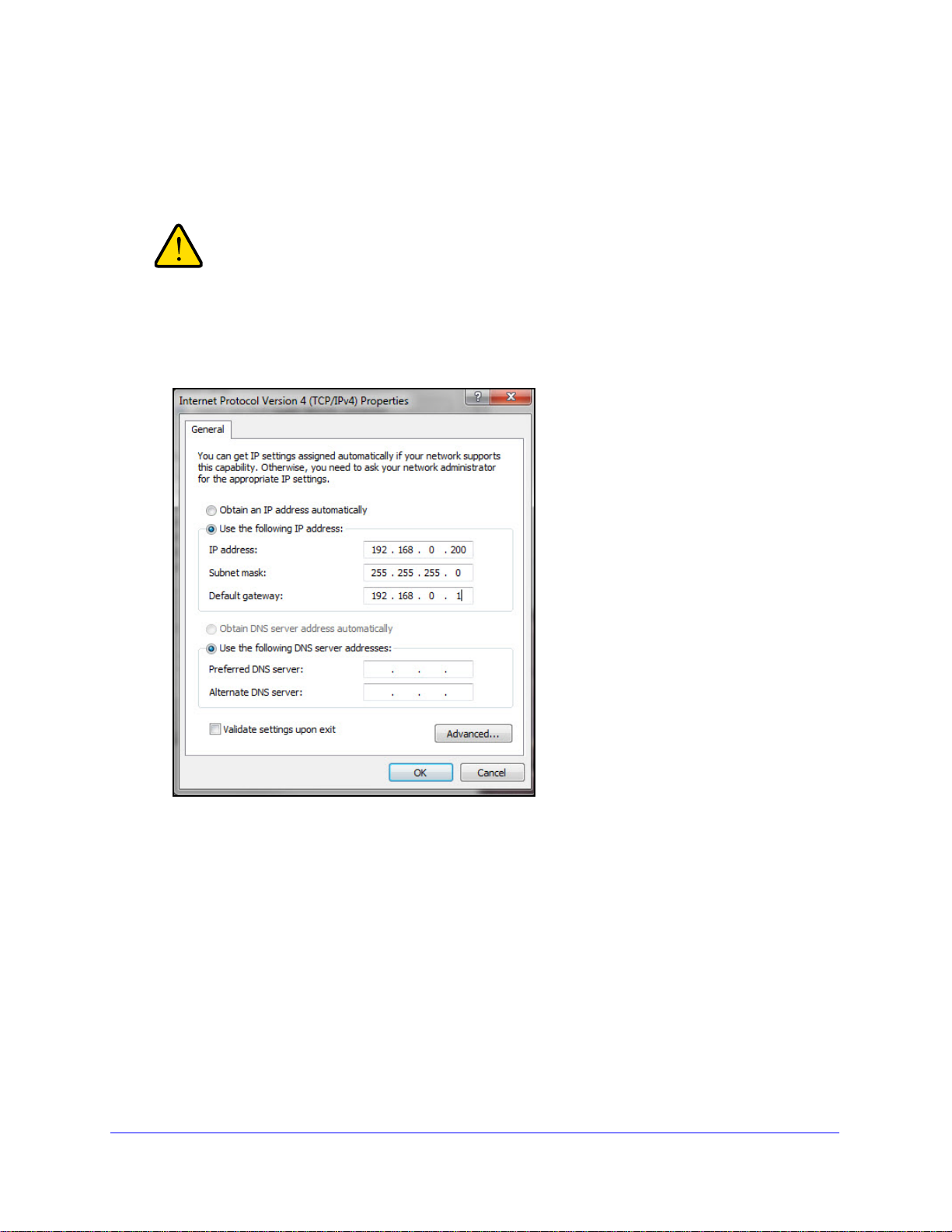
XS712T Smart Switch
WARNING:
5. Select Use the following IP address and set the IP address of the administrative system to
an address in the 192.168.0.0 network, such as 192.168.0.200.
The IP address must be different from that of the switch but within the same subnet.
When you change the IP address of your administrative system,
you lose your connection to the rest of the network. Be sure to
write down your current network address settings before you
change them.
6. Click OK.
To configure a static address on the switch:
1. Use a straig
ht-through cable to connect the Ethernet port on the administrative system
directly to any port on the XS712T.
2. Open a we
b browser on your computer and connect to the management interface.
For more information, see Access the Management Interface from a Web Browser on
page 15.
3. Change th
For more information, see IP Configuration on p
e network settings on the switch to match those of your network.
age 29.
After you change the network settings on the switch, return the network configuration on your
administrative system to the
original settings.
14
Page 15
XS712T Smart Switch
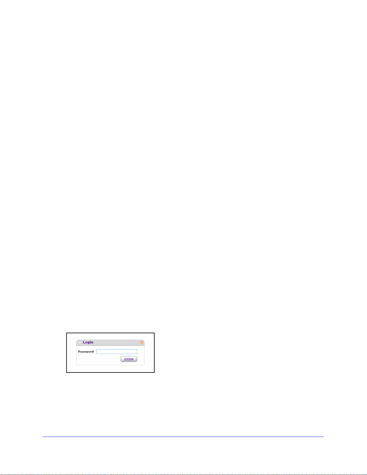
Access the Management Interface from a Web Browser
You must be able to ping the IP address of the switch web management interface from your
administrative system for web access to be available. If you used the Smart Control Center to
set up the IP address and subnet mask, either with or without a DHCP server, use that IP
address in the address field of your web browser. If you did not change the IP address of the
switch from the default value, enter 192.168.0.239 in the address field.
To access the switch management interface, use one of the following methods:
rom the Smart Control Center, select the switch and click Web Browser Access.
• F
• Open
To access the management interface from a web browser:
a web browser and enter the IP address of the switch in the address field.
1. Open
2. Select the
3. Click W
a web browser.
The utility discovers all switches in the sa
system.
switch to access.
eb Browser Access.
me Layer 2 domain as the administrative
A web browser launches and opens to the switch Login screen.
15
Page 16
XS712T Smart Switch
To access the management interface form the Smart Control Center:
1. Open a web browser.
2. Enter th
e IP address of the switch in the address field of the browser.
Understand the User Interfaces
The XS712T Smart Switch software includes a set of comprehensive management functions
for configuring and monitoring the system by using one of the following methods:
• W
eb user interface
• Simple Network Ma
Each of the standards-based management methods allows you to configure a
components of the XS712T Smart Switch software. The method you use to manage the
system depends on your network size and requirements, and on your preference.
This manual describes how to use the web-based interface to manage and monitor the
stem.
sy
Use the Web Interface
To access the switch by using a web browser, the browser must meet the following software
requirements:
• HTML version 4
nagement Protocol (SNMP)
nd monitor the
.0, or later
• HTTP version
• Java Runtime
To log on to the Web interface:
1. Op
2. T
3. Click Lo
en a web browser and enter the IP address of the switch in the web browser address
field.
The login screen displays.
ype the password in the Password field.
The factory default password is password. Passwords are case-sensitive.
After the system authenticates you, the System Information screen displays.
The following figure shows the layout of the
1.1, or later
Environment 1.6 or later
gin.
Smart Switch web interface.
16
Page 17
Links
Configuration status and options
Help
Navigation tab Configuration menus
Logout button
page
Help link
XS712T Smart Switch
Figure 1. Smart Switch Web Interface
Navigation Tabs, Configuration Menus, and Links
The navigation tabs along the top of the web interface give you quick access to the various
switch functions. The tabs are always available and remain constant, regardless of which
feature you configure.
When you select a tab, the features for that tab appear as links directly under the tabs. The
configuration menu links in the b
selected.
The configuration screens for each feature are availa
of the screen. Some items in the menu expand to reveal multiple submenu links, as Figure 2
on page 18 shows. When you click a link that includes multiple su
preceded by a down arrow symbol and exp
lue bar change according to the navigation tab that is
ble as links in the menu on the left side
bmenu links, the item is
ands to display the additional screens.
17
Page 18
Link
Submenu
Links
XS712T Smart Switch
Figure 2. Menu hierarchy
Configuration and Status Options
The area directly under the configuration menus and to the right of the links displays the
configuration information or status for the screen you select. On screens that contain
configuration options, you can input information into fields or select options from drop-down
lists.
Each screen contains access to the HTML-based help that
explains the fields and
configuration options for the screen. Each screen also contains command buttons.
The following table shows the command buttons that are used throughout the screens in the
web in
Table 1. Command buttons
terface:
Button Function
Add Places the new item configured in the heading row of a table.
Apply Sends the updated configuration to the switch.
immediately.
Cancel Abandons the configuration changes on the scree
values.
Delete Removes the selected item.
Refresh Refreshes the screen with the latest information from the device.
Logout Ends the session.
Clear Clears all information and returns the switch to it
Configuration changes take effect
n and resets the data to the previous
s default settings.
18
Page 19
XS712T Smart Switch
Device View
The Device View is a Java applet that displays the ports on the switch. This graphic provides
an alternate way to navigate to configuration and monitoring options. The graphic also
provides information about device ports, current configuration and status, table information,
and feature components.
The Device View is available by selecting System
Device View.
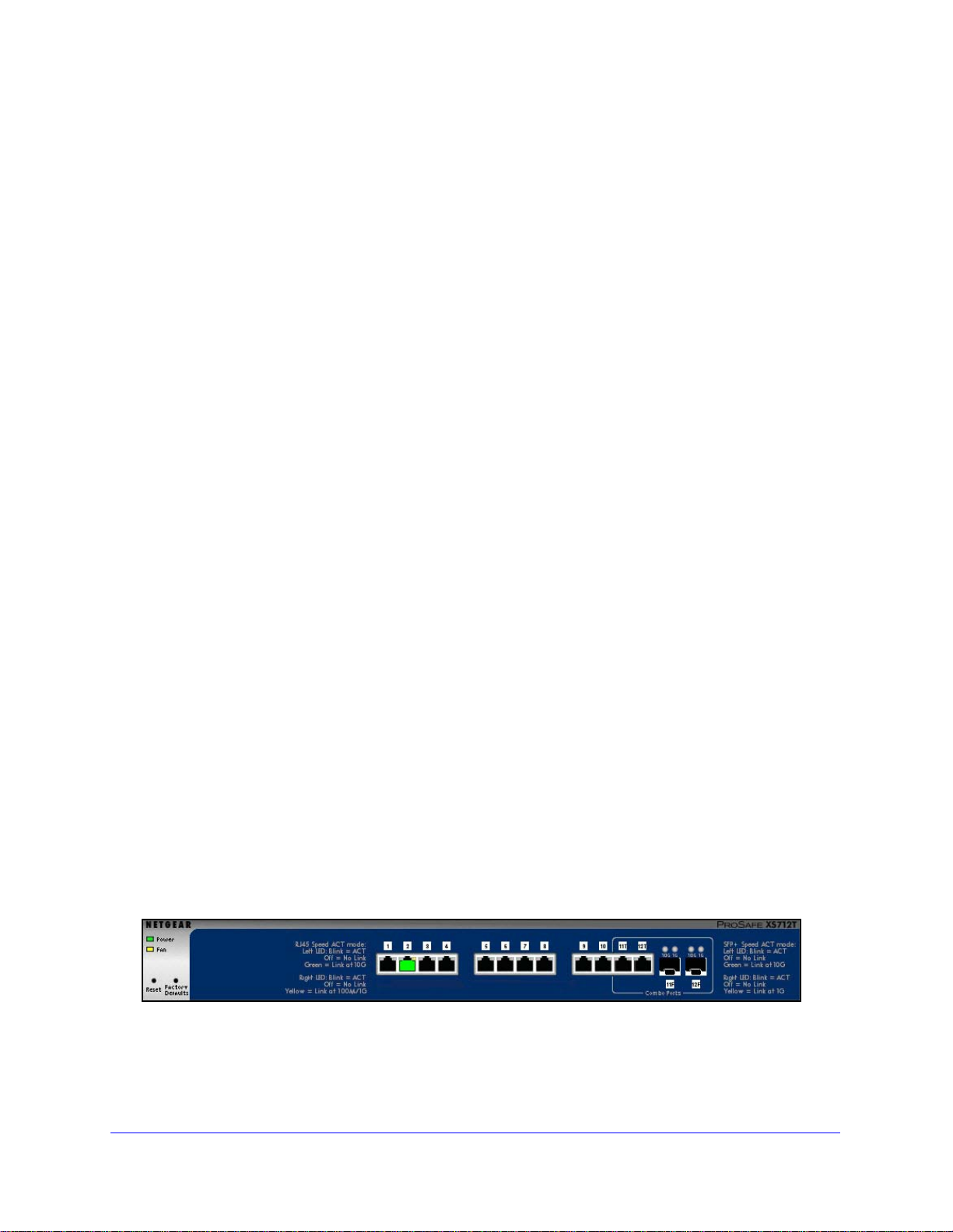
Depending upon the status of the port, the color of a port in the Device View is either red,
g
reen, or black. Green indicates that the port is enabled. Red indicates that an error has
occurred on the port or that the port is administratively disabled. A port that is black does not
have a link.
The port speed LED is either green or yellow.
• Sol
• Blin
• Sol
• Blin
id green. A valid 10 Gbps link is established
king green. Packets transmitting/receiving is occurring at 10 Gbps
id yellow. a valid 100/1000 Mbps link is established
king yellow. packets transmitting/receiving is occurring at 100/1000 Mbps
The System LEDs are located on the left side of the front panel.
Power/Status LED
The Power LED is a bicolor LED that serves as an indicator of power and diagnostic status.
T
he following indications are given by the following LED states:
• A solid gree
n LED indicates that the power is supplied to the switch and operating
normally.
• A solid ye
• No
lit LED indicates that power is disconnected.
llow LED indicates that system is in the boot-up stage.
FAN Status LED
FAN status is indicated as follows:
• A solid ye
• No
lit LED indicates that the fan is operating normally.
llow LED indicates that the fan is faulty.
The following image shows the Device View of the XS712T.
Figure 3. Device view
19
Page 20
XS712T Smart Switch
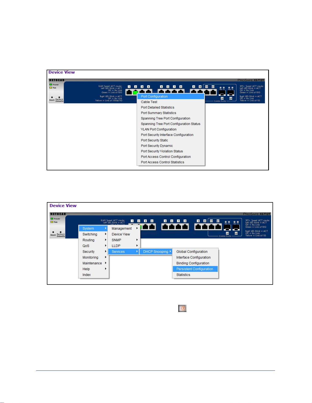
Click the port you want to view or configure to see a menu that displays statistics and
configuration options. Select the menu option to access the screen that contains the
configuration or monitoring options.
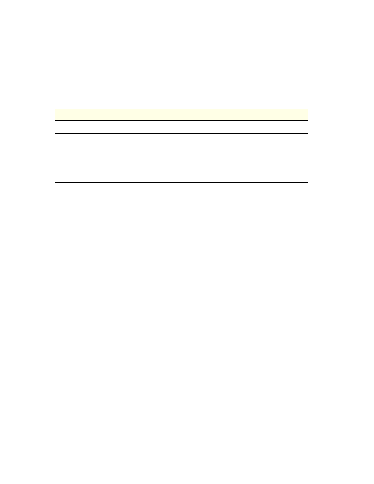
If you click the graphic, but do not click a specific port, the main menu displays, as the
following figure shows. This menu contains the same option as the navigation tabs at the top
of the screen.
Help Access
Every screen contains a button to launch online help , which contains information to
assist in configuring and managing the switch. Th
For example, if the IP Addressing screen is open, the help topic for that screen displays if you
click Help.
e online help screens are context-sensitive.
20
Page 21
XS712T Smart Switch
User-Defined Fields
User-defined fields can contain 1 to 159 characters, unless otherwise noted in the field label
on the configuration screen. All alphanumeric and special characters can be used except for
the following (unless specifically noted for that feature):
Table 2. Disallowed characters in user-defined fields
Character Definition
\ Backslash
/ Forwards slash
* Asterisk
? Question mark
< Less than
> Greater than
| Pipe
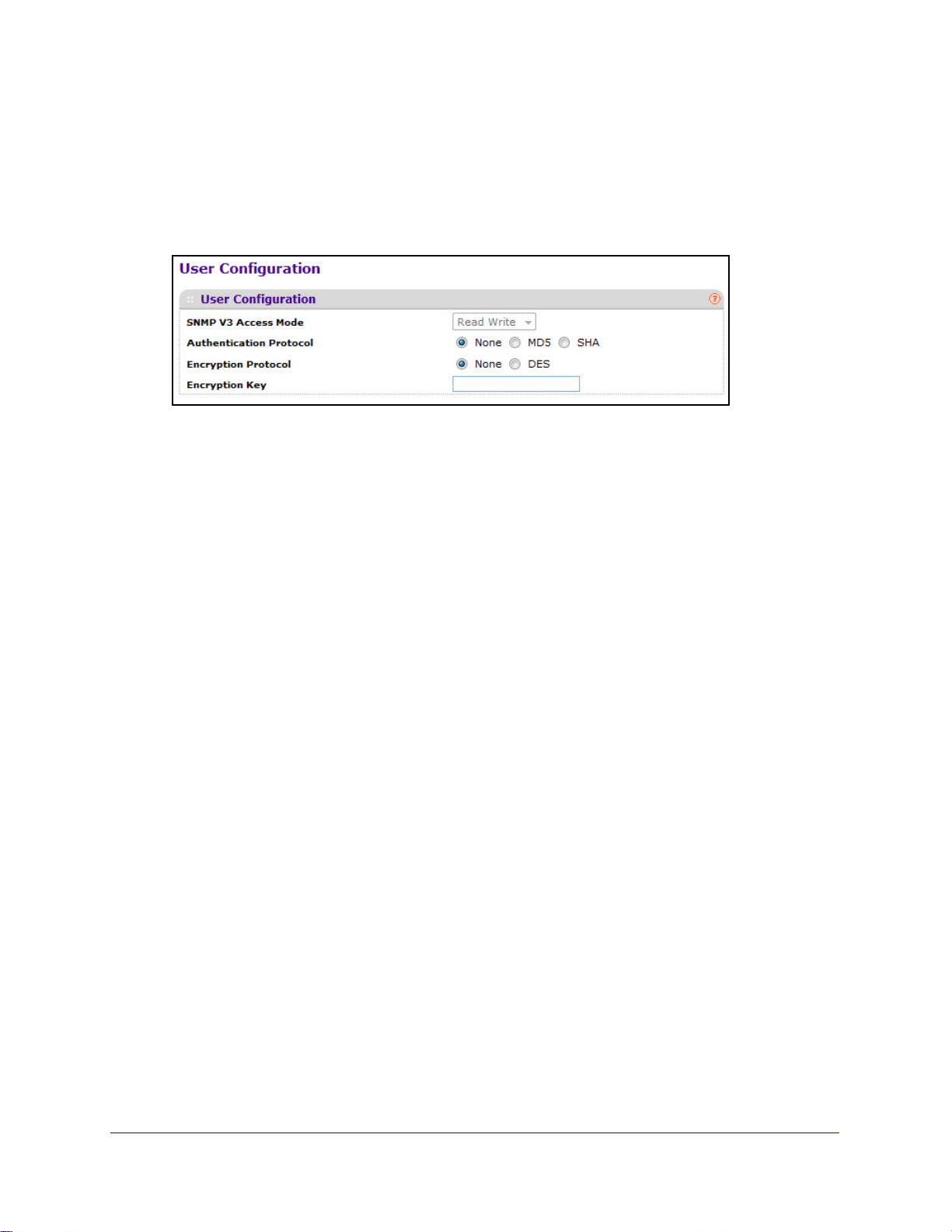
Use SNMPv3
The XS712T Smart Switch software supports the configuration of SNMP groups and users
that can manage traps that the SNMP agent generates.
The XS712T Smart Switch use both standard pub
private MIBs that support additional switch functionality. All private MIBs begin with a hyphen
(-) prefix. The main object for interface configuration is in -SWITCHING-MIB, which is a
private MIB. Some interface configurations also involve objects in the public MIB, IF-MIB.
SNMP is enabled by default. The System Information screen, which is the screen that
isplays after a successful login, displays the information you need to configure an SNMP
d
manager to access the switch. To configure information for SNMPv1 or SNMPv2, see
SNMPV1/V2 on p
age 53.
Any user can connect to the switch using the SNMPv3 proto
encryption, the switch supports only one user which is admin; therefore there is only one
profile that can be created or modified.
lic MIBs for standard functionality and
col, but for authentication and
21
Page 22
XS712T Smart Switch
To configure authentication and encryption settings for the SNMPv3 admin profile by
using the web interface:
1. Select System SNMP SNMPv3 User Configuration.
The User Configuration screen displays.
The SNMPv3 Access Mode is a read-only field that shows the access privileges for the
user account. The admin account always has Read/Write access, and all other accounts
have Read Only access.
o enable authentication, select an Authentication Protocol option.
2. T
If the authentication protocol is MD5 or SHA, the u
ser login password will be used as
SNMPv3 authentication password. To configure the login password, see Change
Password on p
o enable encryption:
3. T
a. In the
age 171.
Encryption Protocol field, select the DES option to encrypt SNMPv3 packets
using the DES encryption protocol.
b. In the
Encryption Key field, enter an encryption code of eight or more alphanumeric
characters.
4. Click Apply.
22
Page 23

XS712T Smart Switch
Interface Naming Convention
The switch supports physical and logical interfaces. Interfaces are identified by their type and
the interface number. All the physical ports are as follows:
• Port
• Port
s 1–10. Copper ports that operate at 100MB, 1G, or 10G.
s 11–12. Combo ports that can act as 100M/1G/10G copper ports or 1G/10G SFP+
ports.
The number of the port is identified on the front panel. You can configure the logical
interfa
ces by using the software. The following table describes the naming convention for all
interfaces available on the switch.
Table 3. Interface naming conventions
Interface Description Example
Physical The physical ports include 10 gigabit ports and are
numbered sequentially starting from one using the following
format: xgX. xg stands for 10G port and X is the port
number.
Link aggregation group (LAG) LAG interfaces are logical interfaces that are only used for
ing functions.
bridg
CPU management interface This is the internal switch interface responsible for the
switch b
configurable and is always listed in the MAC Address
Table.
ase MAC address. This interface is not
xg1, xg2, xg3
l1, l2, l3
c1
23
Page 24
XS712T Smart Switch
Online Help
The Help main navigation tab of the web management interface provides access to the
menus that are described in the following sections:
• Support
• User Guide
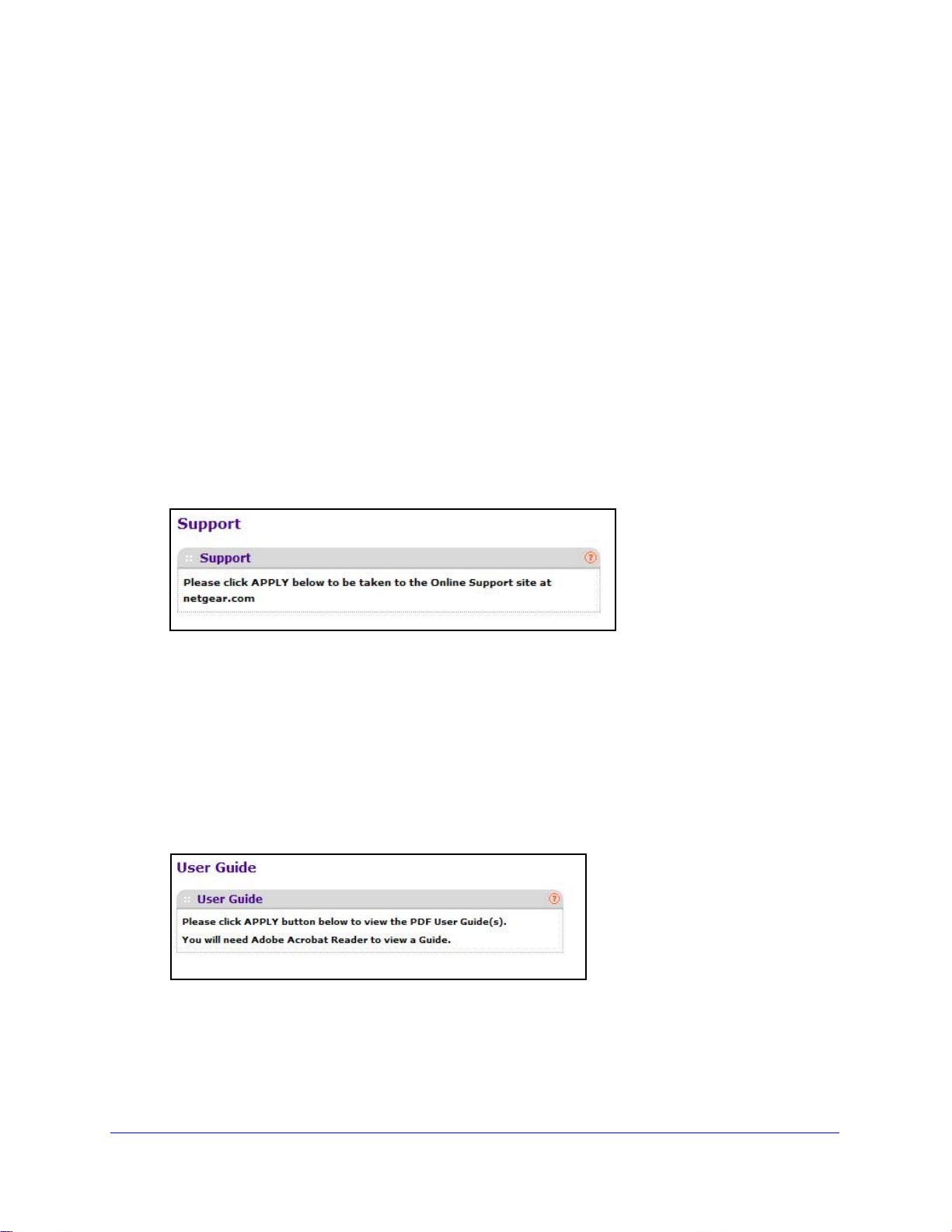
Support
The Support screen provides access to the NETGEAR support website at
support.netgear.com.
To access the support website from the web management interface:
1. Select Help
The Support screen displays.
2. Click Apply to access the NETGEAR support site for the switch.
Support..
User Guide
The XS712T Smart Switch Software Administration Manual (the guide you are now reading)
is available at the NETGEAR download center at downloadcenter.netgear.com.
To access the reference manual online from the web management interface:
1. Select Help
User Guide.
2. Click Apply to access the NETGEAR download center.
3. Enter th
4. Loca
web screen.
e model number of the switch.
te the XS712T Smart Switch Software Administration Manual on the product support
24
Page 25
XS712T Smart Switch
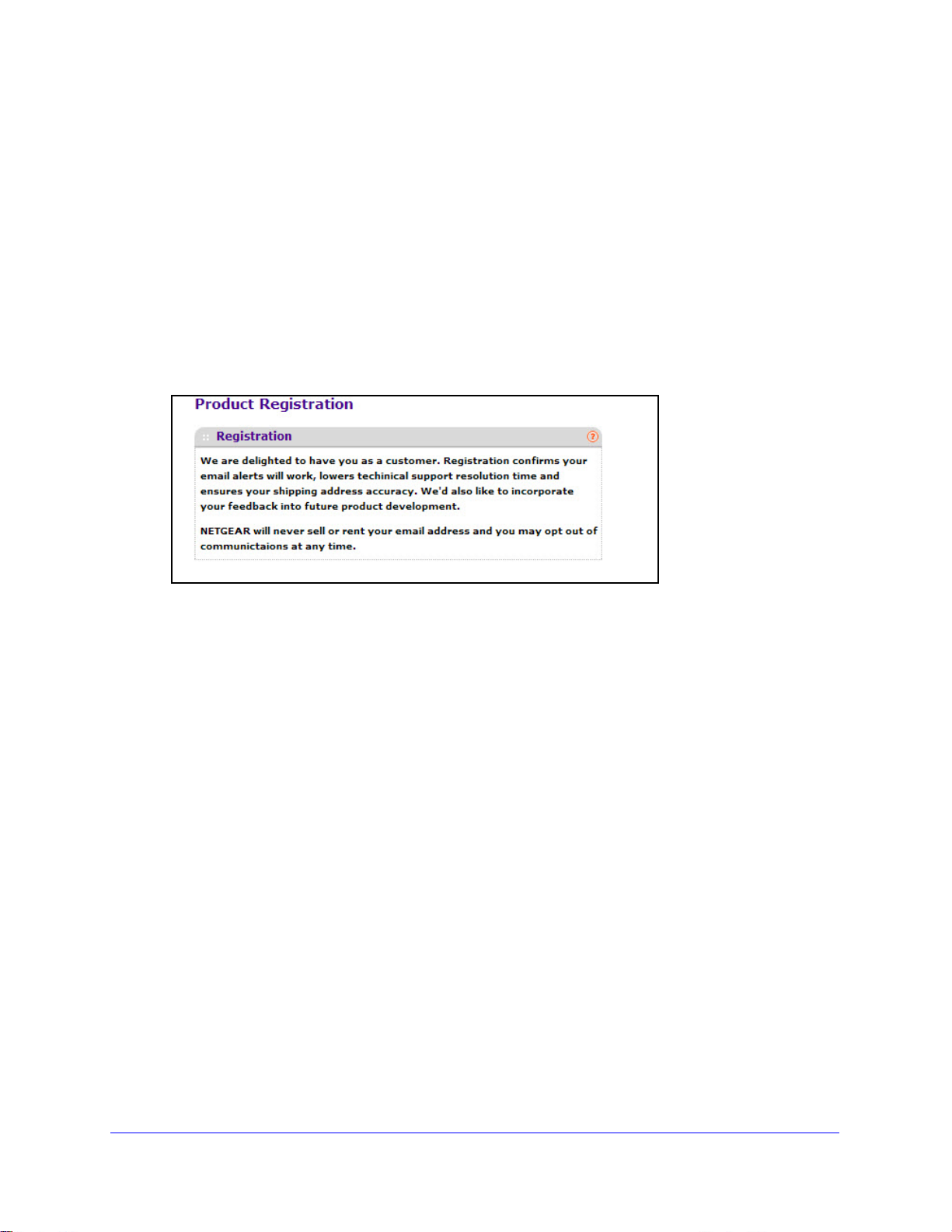
Registration
To qualify for product updates and product warranty, NETGEAR encourages you to register
your product. The first time that you connect to the switch while it is connected to the Internet,
you have the option to register your product. At any time, you can register your product from
the web management interface, or you can visit the NETGEAR website for registration at
https://my.netgear.com/registration/login.aspx.
To register the switch with NETGEAR:
1. Select Hel
The Registration screen displays.
2. Click Register .
A pop-up window opens and displays the NETGEAR pro
3. Complet
4. Click Subm
p > Register.
e the registration form.
it.
duct registration web screen.
25
Page 26

2. Configure System Information
Use the features you access from the System navigation tab to define the switch’s relationship to
its environment. The System navigation tab provides access to the configuration menus
described in the following sections:
• Management
• SNMP
• LLDP
• Services—DHCP Snooping
Management
This section describes how to display the switch status and specify some basic switch
information, such as the management interface IP address, system clock settings, and DNS
information. From the Management configuration menu, you can access the following links:
2
• System Information
• IP Configuration
• IPv6 Network Configuration
• IPv6 Network Neighbor
• Time
• Denial of Service
• DNS
• Green Ethernet
26
Page 27
XS712T Smart Switch
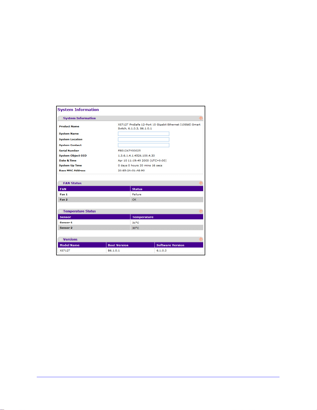
System Information
After a successful login, the System Information screen displays. Use this screen to configure
and view general device information.
To define a system name, location, and contact:
1. Select System
Management System Information.
The System Information screen displays.
2. Define the following fields:
• System Name. Enter th
e name you want to use to identify this switch. You can use
up to 255 alphanumeric characters. The factory default is blank.
• Sys
tem Location. Enter the location of this switch. You can use up to 255
alphanumeric characters. The factory default is blank.
• Sys
tem Contact. Enter the contact person for this switch. You can use up to 255
alphanumeric characters. The factory default is blank.
3. Click App
ly .
The system parameters are applied, and the device is updated.
27
Page 28

XS712T Smart Switch
The following table describes the status information the System Information screen displays.
Table 4. System Information screen status fields
Field Description
Product Name The product name that describes the switch.
Serial Number The serial number of the switch.
System Object ID The base object ID for the switch's enterprise MIB.
Date & Time The current date and time.
System Up Time Displays the number of days, hours, and minutes since the last
system restart.
Base MAC Address The universally assigned network address.
Model Name The model name of the switch.
Temperature Status This table shows temperature of different system sensors. The
temperature is instant and can be refreshed when the REFRESH
button is pressed. The maximum temperature of CPU and MACs
depends on the actual hardware.
Fan Status The screen shows the status of the fans. These fans remove the heat
generated by the power, CPU and other chipsets, make chipsets
work normally. Fan status has three possible values: OK, Failure, Not
Present.
Boot Version The boot code version of the switch.
Software Version The software version of the switch.
28
Page 29
XS712T Smart Switch
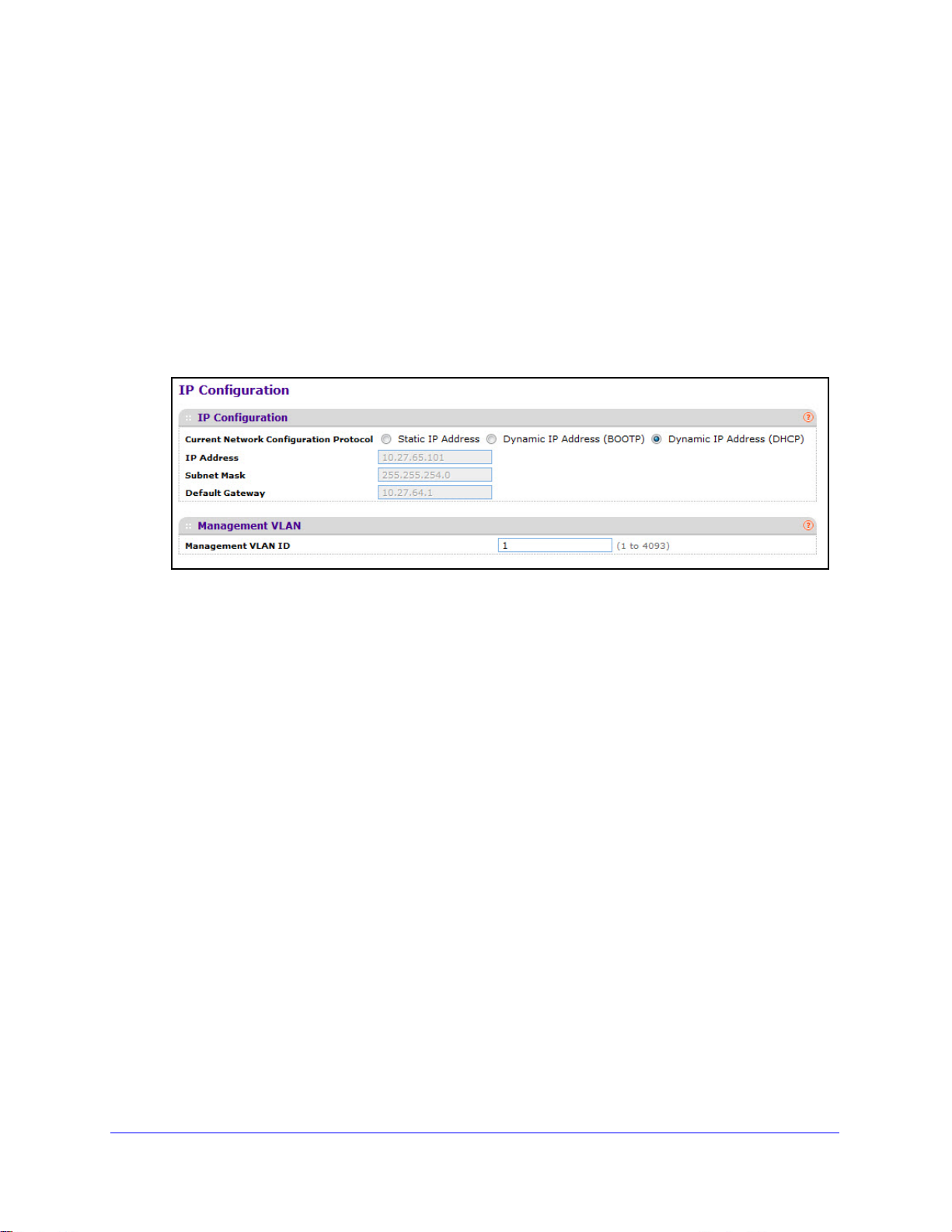
IP Configuration
Use the IP Configuration screen to configure network information for the management
interface, which is the logical interface used for in-band connectivity with the switch through
any of the switch's front-panel ports. The configuration parameters associated with the
switch’s network interface do not affect the configuration of the front panel ports through
which traffic is switched or routed.
To configure the network information for the management interface:
1. Select System
Management IP Configuration.
The IP Configuration screen displays.
2. Select the appropriate radio button to determine how to configure the network information for
the switch management interface:
• Dyn
amic IP Address (DHCP). Specifies that the switch must obtain the IP address
through a DHCP server.
• Dyn
amic IP Address (BOOTP). Specifies that the switch must obtain the IP address
through a BootP server.
• S
tatic IP Address. Specifies that the IP address, subnet mask, and default gateway
must be manually configured. Enter this information in the fields below this radio
button.
3. If you se
• IP
lected the Static IP Address option, configure the following network information:
Address. The IP address of the network interface. The factory default value is
192.168.0.239. Each part of the IP address must start with a number other than zero.
For example, IP addresses 001.100.192.6 and 192.001.10.3 are not valid.
• Sub
net Mask. The IP subnet mask for the interface. The factory default value is
255.255.255.0.
• Default Gateway.
is 192.168.0.254.
The default gateway for the IP interface. The factory default value
29
Page 30

XS712T Smart Switch
4. Specify the VLAN ID for the management VLAN.
Note: Make sure that the VLAN to be configured as the management
VLAN exists. And make sure that the PVID of at least one port that is
a port of the VLAN is the same as the management VLAN ID. For
information about creating VLANs and configuring the PVID for a
port, see VLANs on page 84.
The management VLAN is used to establish an IP connection to the switch from a
workstation that is connected to a port in the same VLAN. If not specified, the active
management VLAN ID is 1 (default), which allows an IP connection to be established
through any port.
When the management VLAN is set to a different value, an IP connection can be made
only through a port that is part of the management VLAN. It is also mandatory that the
port VLAN ID (PVID) of the port to be connected in that management VLAN be the same
as the management VLAN ID.
The management VLAN has the following requirements:
• Only one management VLAN can be active at a time.
• When a new management VLAN is configured, connectivity through the existing
management VLAN is lost.
• The management station should be reconnected to the port in the new management
VLAN.
5. Click Apply.
30
Page 31

XS712T Smart Switch
IPv6 Network Configuration
Use the IPv6 Network Configuration screen to configure the IPv6 network interface, which is
the logical interface used for in-band connectivity with the switch through all of the switch's
front-panel ports. The configuration parameters associated with the switch's network
interface do not affect the configuration of the front-panel ports through which traffic is
switched or routed.
To access the switch over a IPv6 network, you must
initially configure the switch with IPv6
information (IPv6 prefix, prefix length, and default gateway). IPv6 can be configured using
any of the following options:
Pv6 Auto Configuration
• I
• DHCPv6
When in-band connectivity is established, IPv6 information
can be changed using any of the
following:
• SNMP-b
• W
eb-based management
To configure the network information for an IPv6 network:
1. Select System
ased management
Management IPv6 Network Configuration.
A screen similar to the following displays.
2. Next to the Admin Mode field, ensure the Enable radio button is selected.
3. Dete
rmine how the switch acquires an IPv6 address:
• IPv
6 Address Auto Configuration Mode. When enabled, the network interface can
acquire an IPv6 address through IPv6 Neighbor Discovery Protocol (NDP) and
through the use of Router Advertisement messages. When disabled, the network
interface will not use the native IPv6 address auto configuration features to acquire an
IPv6 address. Auto configuration can be enabled only when DHCPv6 is not enabled
on any of the management interfaces.
• DHCPv6. Next to
the Current Network Configuration Protocol field, select DHCPv6 to
enable the DHCPv6 client on the interface. The switch attempts to acquire network
31
Page 32

XS712T Smart Switch
information from a DHCPv6 server. Selecting None disables the DHCPv6 client on
the network interface. When DHCPv6 is enabled, the DHCPv6 Client DUID field
displays the client identifier used by the DHCPv6 client (if enabled) when sending
messages to the DHCPv6 server.
4. In
the IPv6 Gateway field, specify the default gateway for the IPv6 network interface.
The gateway address is in IPv6 global or link-local address format.
5. Option
a. In the
ally, configure one or more static IPv6 addresses for the management interface.
IPv6 Prefix/Prefix Length field, specify the static IPv6 prefix and prefix to the
IPv6 network interface.
The address is in the global address format.
b. In the EUI64 field, select T
rue to enable the Extended Universal Identifier (EUI) flag
for IPv6 address, or select False to omit the EUI flag.
c. Click Add.
6. Click Apply.
IPv6 Network Neighbor
Use the IPv6 Network Neighbor screen to view information about the IPv6 neighbors the
device has discovered through the network interface by using the Neighbor Discovery
Protocol (NDP).
To access the screen, select System
similar to the following displays.
Management IPv6 Network Neighbor. A screen
Table 5. IPv6 neighbor table fields
Field Description
IPv6 Address The IPv6 address of the neighbor.
MAC Address The MAC address associated with an interface.
IsRtr Indicates whether the neighbor is a router. If the neighbor is a router, the value is
rue. If the neighbor is not a router, the value is False.
T
32
Page 33

XS712T Smart Switch
Table 5. IPv6 neighbor table fields (Continued)
Field Description
Neighbor State The state of the neighbor cache entry. The following are the states for dynamic
entries in the IPv6 neighbor discovery cache:
• Reach. The neighbor is reachable through the network interface.
• Stale. The neighbor is not known to be reachable, and the switch will begin
the process to reach the neighbor.
• Delay. The neighbor is not known to be reachable, and upper-layer
protocols are attempting to provide reachability information.
• Probe. The neighbor is not known to be reachable, and the device is
attempting to probe for this neighbor.
• Unknown. The reachability status cannot be determined.
Last Updated The amount of time that has passed since the neighbor entry was last updated.
Time
The switch supports the Simple Network Time Protocol (SNTP). You can also set the system
time manually
SNTP assures accurate network device clock time synchronization up to the millisecond.
Time synchronization is performed by a network SNTP server. The switch software operates
only as an SNTP client and cannot provide time services to other systems.
Time sources are established by stratums. Stratums define the accuracy of the reference
clock. The higher the stratum (where zero is the highest), the more accurate the clock. The
device receives time from stratum 1 and above since it is itself a stratum 2 device.
Information received from SNTP servers is evaluated based on the time level and server
type. SNTP time definitions are assessed and determined by the following time levels:
• T1: Time at which the original request was sent by the client.
• T2: Time at which the original request was received by the server.
• T3: Time at which the server sent a reply.
• T4: Time at which the client received the server's reply.
The device can poll Unicast server types for the server time.
Polling for unicast information is used for polling a server for which the IP address is known.
SNTP servers that have been configured on the device are the only ones that are polled for
synchronization information. T1 through T4 are used to determine server time. This is the
preferred method for synchronizing device time because it is the most secure method. If this
method is selected, SNTP information is accepted only from SNTP servers defined on the
device using the SNTP Server Configuration screen.
The device retrieves synchronization information, either by actively requesting information or
at every poll interval.
33
Page 34

XS712T Smart Switch
Time Configuration
Use the Time Configuration screen to view and adjust date and time settings.
To manually configure the time:
1. Select System
Management Time Time Configuration.
The Time Configuration screen displays.
2. Next to the Clock Source field, select Local.
3. In
the Date field, enter the date in the DD/MM/YYYY format.
the Time field, enter the time in HH:MM:SS format.
4. In
Note: If you do not enter a date and time, the switch will calculate the date
and time using the CPU’s clock cycle.
5. Click Apply.
To configure the time by using SNTP:
1. Select System
2. Next to the Clock Source field,
Management Time Time Configuration.
select SNTP.
The screen refreshes, and additional fields appear.
34
Page 35

XS712T Smart Switch
3. Next to the Client Mode field, select Unicast or Broadcast:
• Unic
ast. SNTP operates in a point-to-point fashion. A unicast client sends a request
to a designated server at its unicast address and expects a reply from which it can
determine the time and, optionally the round-trip delay and local clock offset relative
to the server.
• Broadc
ast. SNTP operates in the same manner as multicast mode but uses a local
broadcast address instead of a multicast address. The broadcast address has a
single subnet scope while a multicast address has Internet wide scope.
4. Opt
ionally, configure the following settings to non-default values:
• Port. T
• Unic
he local UDP port to listen for responses/broadcasts.
ast Poll Interval. The interval, in seconds, between unicast poll requests
expressed as a power of two when configured in unicast mode.
• Broadc
ast Poll Interval. The interval, in seconds, between broadcast poll requests
expressed as a power of two when configured in broadcast mode. Broadcasts
received prior to the expiry of this interval are discarded.
• Unic
ast Poll Timeout. The timeout value, in seconds, to wait for an SNTP response
when configured in unicast mode.
• Unic
ast Poll Retry. The number of times to retry a request to an SNTP server after
the first time-out before attempting to use the next configured server when configured
in unicast mode.
35
Page 36

XS712T Smart Switch
• Time Zone Name. The acronym that represents the time zone. This field is not
validated against an official list of time zone acronyms.
• Hours Offset. The number of hours the system clock is offset from UTC, which is
also known as Greenwich Mean Time (GMT).
• Minutes Offset. The number of minutes the system clock is offset from UTC.
5. Click Apply.
6. Use the SNTP Server Configuration screen to configure the SNTP server settings, as
described in
SNTP Server Configuration on page 37.
The SNTP Global Status table on the Time Configuration screen displays information about
the system’s SNTP client. The following table describes the SNTP Global Status fields.
Table 6. Time Configuration status fields
Field Description
Version Specifies the SNTP Version the client supports.
Supported Mode Specifies the SNTP modes the client supports. Multiple modes can be
supported by a client.
Last Update Time Specifies the local date and time (UTC) the SNTP client last updated
the system clock.
Last Attempt Time Specifies the local date and time (UTC) of the last SNTP request or
receipt of an unsolicited message.
Last Attempt Status Specifies the status of the last SNTP request or unsolicited message for
both unicast and broadcast modes. If no message has been received
from a server, a status of Other is displayed. These values are
appropriate for all operational modes:
• Other. None of the following enumeration values.
• Success. The SNTP operation was successful and the system time
was updated.
• Request Timed Out. A directed SNTP request timed out without
receiving a response from the SNTP server.
• Bad Date Encoded. The time provided by the SNTP server is not
valid.
• Version Not Supported. The SNTP version supported by the
server is not compatible with the version supported by the client.
• Server Unsynchronized. The SNTP server is not synchronized
with its peers. This is indicated via the 'leap indicator' field on the
SNTP message.
• Server Kiss Of Death. The SNTP server indicated that no further
queries were to be sent to this server. This is indicated by a stratum
field equal to 0 in a message received from a server.
Server IP Address Specifies the IP address of the server for the last received valid packet.
If no message has been received from any server, an empty string is
shown.
36
Page 37

XS712T Smart Switch
Table 6. Time Configuration status fields (Continued)
Field Description
Address Type Specifies the address type of the SNTP Server address for the last
received valid packet.
Server Stratum Specifies the claimed stratum of the se
packet.
Reference Clock Id Specifies the reference clock identifier of the server for the last received
valid packet.
Server Mode Specifies the mode of the server for the last
Unicast Sever Max Entries Specifies the maximum number of unicast server entries that can be
configured on this client.
Unicast Server Current
tries
En
Specifies the number of current valid unicast server entries configured
for this client.
rver for the last received valid
received valid packet.
Click Refresh to refresh the screen with the most current data from the switch.
SNTP Server Configuration
Use the SNTP Server Configuration screen to view and modify information for adding and
modifying Simple Network Time Protocol SNTP servers.
To configure a new SNTP server:
1. Select System
The SNTP Server Configuration screen displays.
Management Time SNTP Server Configuration.
2. From the Server Type list, select the type of SNTP address to enter in the Address field,
which is either an IP address (IPv4) or hostname (DNS).
3. Unde
4. If the UDP
r the Address field, specify the IP address or the hostname of the SNTP server.
port on the SNTP server to which SNTP requests are sent is not the standard
port (123), specify the port number.
37
Page 38

XS712T Smart Switch
5. Under the Priority field, specify the order in which to query the servers.
The SNTP client on the device continues sending SNTP requests to different servers until
a successful response is received or all servers are exhausted. The request is sent to an
SNTP server with a priority value of 1 first, then to a server with a priority value of 2, and
so on. If more than one server has the same priority, the SNTP client contacts the servers
in the order that they appear in the table.
6. Under the Version field, specify the NTP version running on the server.
7. Click Add.
8. Repeat the previous steps to add additional SNTP servers. You can configure up to three
SNTP servers.
To remove an SNTP server:
1. Select the check box next to the configured server to remove.
2. Click Delete.
To change the settings for an existing SNTP server:
1. Select the check box next to the configured server.
2. Specify new values in the available fields.
3. Click Apply.
The SNTP Server Status table displays status information about the SNTP servers
configured on your switch. The following table describes the SNTP Global Status fields.
Table 7. SNTP server status fields
Field Description
Address Specifies all the existing Server Addresses. If no Server configuration exists,
a message saying “No SNTP server exists” flashes on the screen.
Last Update Time Specifies the local date and time (UTC) that the response from this server
was used to update the system clock.
Last Attempt Time Specifies the local date and time (UTC) that this SNTP server was last
queried.
38
Page 39

XS712T Smart Switch
Table 7. SNTP server status fields (Continued)
Field Description
Last Attempt Status Specifies the status of the last SNTP request to this server. If no packet has
been received from this server, a status of Other is displayed:
er. None of the following enumeration values.
• Oth
ccess. The SNTP operation was successful and the system time was
• Su
updated.
quest Timed Out. A directed SNTP request timed out without
• Re
receiving a response from the SNTP server.
d Date Encoded. The time provided by the SNTP server is not valid.
• Ba
• Version Not Supported. The SNTP version supported by the server is
not compatible with the version supported by the client.
rver Unsynchronized. The SNTP server is not synchronized with its
• Se
peers. This is indicated via the 'leap indicator' field on the SNTP
message.
rver Kiss Of Death. The SNTP server indicated that no further
• Se
queries were to be sent to this server. This is indicated by a stratum field
equal to 0 in a message received from a server.
Requests Specifies the number of SNTP requests made to this server since last agent
oot.
reb
Failed Requests Specifies the number of failed SNTP requests made to this server since last
oot.
reb
Click Refresh to refresh the screen with the most current data from the switch.
Summer Time Configuration
Use the Summer Time Configuration screen to configure settings for summer time, which is
also known as daylight saving time. Used in some countries around the world, summer time
is the practice of temporarily advancing clocks during the summer months. Typically clocks
are adjusted forward one or more hours near the start of spring and are adjusted backward in
autumn.
To configure the summer time settings:
1. Selec
t click System Management Time Summer Configuration.
The Time Configuration screen displays.
39
Page 40

XS712T Smart Switch
2. Next to the Summer Time field, select one of the following options:
• Recurring. Summer time occurs at the same time every year. The start and end times
and dates for the time shift must be manually configured.
• Recurring EU. The system clock uses the standard recurring summer time settings
used in countries in the European Union. When this field is selected, the rest of the
applicable fields on the screen are automatically populated and cannot be edited.
• Recurring USA. The system clock uses the standard recurring daylight saving time
settings used in the United States. When this field is selected, the rest of the
applicable fields on the screen are automatically populated and cannot be edited.
• Non-Recurring. Summer time settings are in effect only between the start date and
end date of the specified year. When this mode is selected, the summer time settings
do not repeat on an annual basis.
3. If the selected summer time mode is Recurring or Non Recurring, set the start and end times
for the time shift:
• Begins At: From the appropriate lists, select the date and time on which summer time
begins.
• Ends At: From the appropriate lists, select the date and time on which summer time
ends.
4. Next to the Offset field, specify the number of minutes to shift the summer time from the
standard time.
5. Next to the Zone field, specify the acronym associated with the time zone when summer
time is in effect.
This field is not validated against an official list of time zone acronyms.
6. Click Apply.
The Summer Time Status table shows information about the summer time settings and
whether the time shift for summer time is currently in effect.
Denial of Service
Use the Denial of Service (DoS) feature to configure DoS control. The switch software
provides support for classifying and blocking specific types of DoS attacks.
Configure Auto-DoS
The Auto-DoS Configuration screen lets you automatically enable all the DoS features
available on the switch, except for the L4 Port attack. For information about the types of DoS
attacks the switch can monitor and block, see
Configure Denial of Service on page 41.
To enable the Auto-DoS feature:
1. Select System Management Denial of Service Auto-DoS Configuration.
The Auto-DoS Configuration screen displays.
40
Page 41

XS712T Smart Switch
2. Next to the Auto-DoS Mode field, select Enable.
When an attack is detected, a warning message is logged to the buffered log and is sent
t
o the Syslog server. At the same time, the port is shut down and can be enabled only
manually by the admin user.
3. Click App
ly .
Configure Denial of Service
The Denial of Service Configuration screen lets you to select which types of DoS attacks for
the switch to monitor and block.
To configure individual DoS settings:
1. Select System
The Denial of Service Configuration scree
Management Denial of Service Denial of Service Configuration.
n displays.
2. Select the types of DoS attacks for the switch to monitor and block and configure any
associated values:
41
Page 42

XS712T Smart Switch
• Denial of Service Min TCP Header Size: Specify the minimum TCP header size
allowed. If DoS TCP Fragment is enabled, the switch will drop packets that have a
TCP header smaller than the configured value.
• Denial of Service ICMPv4: Enabling ICMPv4 DoS prevention causes the switch to
drop ICMPv4 packets that have a type set to ECHO_REQ (ping) and a size greater
than the configured ICMPv4 Pkt Size. The factory default is disabled.
• Denial of Service Max ICMPv4 Packet Size: Specify the maximum ICMPv4 packet
size allowed. If ICMPv4 DoS prevention is enabled, the switch will drop IPv4 ICMP
ping packets that have a size greater than the configured value.
• Denial of Service ICMPv6: Enabling ICMPv6 DoS prevention causes the switch to
drop ICMPv6 packets that have a type set to ECHO_REQ (ping) and a size greater
than the configured ICMPv6 Pkt Size.
• Denial of Service Max ICMPv6 Packet Size: Specify the Max IPv6 ICMP packet size
allowed. If ICMPv6 DoS prevention is enabled, the switch will drop IPv6 ICMP ping
packets that have a size greater than this configured Max ICMPv6 Pkt Size.
• Denial of Service First Fragment: Enabling First Fragment DoS prevention causes
the switch to check DoS options on first fragment IP packets when switch are
receiving fragmented IP packets. Otherwise, switch ignores the first fragment IP
packages.
• Denial of Service ICMP Fragment: Enabling ICMP Fragment DoS prevention
causes the switch to drop ICMP Fragmented packets.
• Denial of Service SIP=DIP: Enabling SIP=DIP DoS prevention causes the switch to
drop packets that have a source IP address equal to the destination IP address.
• Denial of Service SMAC=DMAC: Enabling SMAC=DMAC DoS prevention causes
the switch to drop packets that have a source MAC address equal to the destination
MAC address.
• Denial of Service TCP FIN&URG&PSH: Enabling TCP FIN & URG & PSH DoS
prevention causes the switch to drop packets that have TCP Flags FIN, URG, and
PSH set and TCP Sequence Number equal to 0.
• Denial of Service TCP Flag&Sequence: Enabling TCP Flag DoS prevention causes
the switch to drop packets that have TCP control flags set to 0 and TCP sequence
number set to 0.
• Denial of Service TCP Fragment: Enabling TCP Fragment DoS prevention causes
the switch to drop packets that have a TCP payload where the IP payload length
minus the IP header size is less than the minimum allowed TCP header size.
• Denial of Service TCP Offset: Enabling TCP Offset DoS prevention causes the
switch to drop packets that have a TCP header Offset set to 1.
• Denial of Service TCP Port: Enabling TCP Port DoS prevention causes the switch to
drop packets that have TCP source port equal to TCP destination port.
• Denial of Service TCP SYN: Enabling TCP SYN DoS prevention causes the switch
to drop packets that have TCP Flags SYN set.
• Denial of Service TCP SYN&FIN: Enabling TCP SYN & FIN DoS prevention causes
the switch to drop packets that have TCP Flags SYN and FIN set.
42
Page 43

3. Click Apply.
XS712T Smart Switch
43
Page 44

XS712T Smart Switch
DNS
You can use these screens to configure information about DNS servers the network uses and
how the switch operates as a DNS client.
Configure DNS
Use this screen to configure global DNS settings and DNS server information.
To configure the global DNS settings:
1. Select System
The DNS Configuration screen displays.
2. Specify whether to enable or disable the administrative status of the DNS Client.
• Enable:
domain name. The DNS is enabled by default.
• Disable:
3. Enter th
When the system is performing a lookup on an unqualified hostname, this field is
provided
the user enters test, then test is changed to test.netgear.com to resolve the name).
e DNS default domain name to include in DNS queries.
as the domain name (for example, if default domain name is netgear.com and
Management DNS DNS Configuration.
Allow the switch to send DNS queries to a DNS server to resolve a DNS
Prevent the switch from sending DNS queries.
4. Under th
queries.
5. Click Add.
You can specify up to eight DNS servers. The Prefe
preference order. The preference is set in the order created.
6. Click Apply
effect immediately.
e DNS Server field, specify the IPv4 address to which the switch sends DNS
rence field displays the server
to send the updated configuration to the switch. Configuration changes take
44
Page 45

XS712T Smart Switch
Configure and View Hostname-to-IP Address Information
Use this screen to manually map host names to IP addresses or to view dynamic DNS
mappings.
To add a static entry to the local DNS table:
1. Select Sy
2. The DNS Host Conf
stem Management DNS Host Configuration.
iguration screen displays.
3. Under the Host Name field, specify the static host name to add.
4. Unde
r the IPv4/IPv6 Address field, specify the IP address to associate with the hostname.
5. Click Add.
To remove an entry from the static DNS table:
1. Select
2. Click Dele
To change the hostname or IP address in an entry:
1. Select
2. Ente
the check box next to the entry to remove.
te.
the check box next to the entry to update.
r the new information in the appropriate field.
3. Click App
The Dynamic Host Configuration table shows host na
ly .
me-to-IP address entries that the switch
has learned. The following table describes the dynamic host fields:
Table 8. Dynamically learned host name mapping information
Field Description
Host Lists the host name you assign to the specified IP address.
To ta l Amount of time since the dynamic entry w
Elapsed Amount of time since the dynamic
Type The type of the dynamic entry.
Addresses Lists the IP address asso
ciated with the host name.
as first added to the table.
entry was last updated.
Click Clear to delete Dynamic Host Entries. The table will be repopulated with entries as they
are learned.
45
Page 46

XS712T Smart Switch
Green Ethernet
The Green Ethernet feature can help reduce the amount of power the switch uses. The
switch supports Energy Efficient Ethernet (EEE).
To configure the administrative mode of Energy Efficient Ethernet:
1. Select System
The Green Ethernet Configuration screen displays.
2. Enable or disable the EEE mode.
• Enable.
transition to low-power mode to save power.
• Disable.
3. Click Apply.
Management Green Ethernet Green Ethernet Configuration.
When the send and receive sides of a link are lightly loaded, the port can
Provide full power to the PHY regardless of the link load.
Green Ethernet Interface Configuration
Use this screen to configure per-port Green Ethernet settings.
To configure the Green Ethernet Interface settings:
1. Select System
Configuration.
Management Green Ethernet Green Ethernet Interface
The Green Ethernet Interface Configuration screen displays.
46
Page 47

2. Select the port(s) to configure.
• T
o configure a single port, select the check box associated with it, or type the port
number in the Go To Interface field and click Go.
• T
o configure multiple ports with the same settings, select the check box associated
with each port to configure.
• T
o configure all ports with the same settings, select the check box in the heading row.
XS712T Smart Switch
3. Use the EEE Mode list to administratively enable or
When this mode is enabled and the send and receive sides of
disable EEE for the selected ports.
a link are lightly loaded, the
port can transition to low-power mode.
4. Click App
ly .
Green Ethernet Detail
Use this screen to view detailed per-port Green Ethernet information and to enable or disable
Green Ethernet settings on a single port. Using the Green Ethernet features allows for power
consumption savings.
To configure Green Ethernet mode settings for a port:
1. Click System
The Port Green Mode Statistics screen displays.
Management Green Ethernet Green Ethernet Detail.
47
Page 48

XS712T Smart Switch
2. From the Interface list, select the interface to configure.
3. Enable
or disable the administrative mode of EEE on the port:
When this mode is enabled and the send and receive sides of a link are lightly loaded, the
port can tra
nsition to low power mode.
4. Click Apply.
The Local Device Information table displays informatio
n about the Green Ethernet status and
statistics on the port.
Table 9. Green Ethernet local device information
Field Description
Cumulative Energy Saved on this port due
to Green Mode(s) (Watts * Hours)
Rx Low Power Idle Event Count The number of times the local interface has entered
Rx Low Power Idle Duration
Tx Low Power Idle Event Count The number of times the link partner has entered a
(uSec) The amount of time (in 10 microsecond increments) the
The energy savings per port, per hour.
low-power idle state.
local interface has spent in a low-power idle state.
ower idle state.
low-p
a
48
Page 49

XS712T Smart Switch
Table 9. Green Ethernet local device information (Continued)
Field Description
Tx Low Power Idle Duration (uSec) The amount of time (in 10 microsecond increments) the
link partner has spent in a low-power idle state.
Tw_sys_tx (uSec) The value of Tw_sys that the local system can support.
This value is updated by the EEE DLL Transmitter state
diagram
Tw_sys_tx Echo (uSec) The remote system's transmit Tw_sys that was used by
the local system to compute the Tw_sys that it wants to
request from the remote system.
Tw_sys_rx (uSec) The value of Tw_sys that the local system requests from
the remote system. This value is updated by the EEE
Receiver L2 state diagram.
Tw_sys_rx Echo (uSec) The value of the remote system’s receive Tw_sys that
was used by the local system to compute the Tw_sys that
it can support
Fallback Tw_sys (uSec) The value of fallback Tw_sys that the local system
requests from the remote system. This value is updated
by the local system software.
Tx_dll_enabled The initialization status of the EEE transmit Data Link
Layer management function on the local system.
Tx_dll_ready The transmit Data Link Layer ready status. This variable
indicates that the tx system initialization is complete and
is ready to update/receive LLDPDU containing EEE TLV.
This variable is updated by the local system software.
Rx_dll_enabled The status of the EEE capability negotiation on the local
system.
Rx_dll_ready The receive Data Link Layer ready status. This variable
indicates that the rx system initialization is complete and
is ready to update/receive LLDPDU containing EEE TLV.
This variable is updated by the local system
software.
Time Since Counters Last Cleared The amount of time that has passed since the Green
Ethernet information for this port was last cleared.
Green Ethernet Summary
This screen summarizes the Green Ethernet Summary settings currently in use. To access
this screen, select System
Management Green Ethernet Green Ethernet Summary.
A screen similar to the following displays.
49
Page 50

XS712T Smart Switch
Figure 4. Green Ethernet summary screen
The following table describes the information the power saving table displays.
Table 10. Green Ethernet power saving information
Field Description
Current Power Consumption The power consumption (in mWatts) of the all the ports on the
switch
Estimated Percentage Power
ng
Savi
Cumulative Energy Saving
(Watts*Hours)
The percentage of power saving due to the Green Ethernet
features on the switch
The cumulative of energy savings on the switch
50
Page 51

XS712T Smart Switch
The following table describes the information in the Green Ethernet feature support table.
Table 11. Green Ethernet support information
Field Description
Unit The ID number for the switch.
Green Features supported on this
unit
The Green Ethernet feature(s) supported on this unit.
The following table describes the information in the Green Ethernet interface table.
Table 12. Green Ethernet interface information
Field Description
Interface The interface associated with the rest of the data in the row.
EEE Admin Mode The administrative status of the EEE feature on the interface.
Click Refresh to refresh the screen with the most current data from the switch.
View and Configure Green Ethernet LPI History
Use this screen to configure and view the Green Ethernet low power idle (LPI) history.
Viewing the Green Ethernet LPI History feature allows you to view the Green Ethernet history
on the switch.
To configure the LPI settings:
1. Select Sy
The Port GreenMode EEE History screen displays
stem Management Green Ethernet Green Ethernet LPI History.
2. Next to the Sampling Interval field, specify the frequency, in seconds, at which EEE LPI
history entries are collected.
This configuration is applied on all interfaces on the switch.
3. Next to th
e Max Samples to keep field, specify the maximum number of LPI samples to
keep in the history buffer.
51
Page 52

XS712T Smart Switch
This configuration is applied on all interfaces on the switch.
4. Click Apply.
To view per-interface LPI history information, select the int
erface with the information to view
from the Interface list. The screen refreshes and displays the LPI history for the selected
interface.
The following table describes the st
Table 13. LPI history information
Field Description
Percentage LPI time The percentage of time spent in LPI mode on the switch
Sample No. The current sample number. When the number increases to the
Time Since The Sample Was
corded
Re
Percentage Time spent in LPI
mode since
Percentage Time spent in LPI
mode since
last sample
last reset
atus fields on the screen.
ximum it rolls over and begins at 1.
ma
The amount of time that has passed since the last LPI history
sample was recorded. Each time the screen is refreshed it shows
a different time as it reflects the difference in current time and time
at which the sample was recorded.
The percentage of time spent in LPI mode since the last sample
was recorded.
The percentage of time spent in LPI mode since the switch was
reset.
5. Click Apply.
52
Page 53

XS712T Smart Switch
SNMP
This section describes how to configure the Simple Network Management Protocol (SNMP)
version 1 and SNMP version 2 information on the switch. For information about configuring
the SNMPv3 administrative profile, see Use SNMPv3 on p
SNMPV1/V2
The screens under the SNMPV1/V2 link allow you to configure SNMPv1/v2 community
information, traps, and trap flags.
Configure the SNMP Community
By default, two SNMP Communities exist:
age 21.
• Private
• Pub
These are well-known communities. Use this screen to change the defaults or to add other
communities. Only the
switch using the SNMPv1 and SNMPv2c protocols. Only those communities with read/write
level access can be used to change the configuration using SNMP.
Use this screen when you are using the SNMPv1 and SNMPv2c protocol.
To add an SNMP community:
1. Select System
The Community Configuration screen displays.
2. Next to Manag
, with Read/Write privileges and status set to Enable.
lic, with Read Only privileges and status set to Enable.
communities that you define using this screen will have access to the
SNMP SNMP V1/V2 Community Configuration.
ement Station IP, specify the IP address of the management station.
3. Next to Manag
management station IP address.
Together, the Management Station IP and the Management Station IP Mask denote a
nge of IP addresses from which SNMP clients can use that community to access this
ra
device. If either (Management Station IP or Management Station IP Mask) value is
0.0.0.0, access is allowed from any IP address. Otherwise, every client’s address is
ANDed with the mask, as is the Management Station IP Address; and, if the values are
equal, access is allowed. For example, if the Management Station IP and Management
Station IP Mask parameters are 192.168.1.0/255.255.255.0, then any client whose
address is 192.168.1.0 through 192.168.1.255 (inclusive) will be allowed access. To allow
ement Station IP Mask, specify the subnet mask to associate with the
53
Page 54

XS712T Smart Switch
access from only one station, use a Management Station IP Mask value of
255.255.255.255, and use that machine’s IP address for Client Address.
4. Next to Community String, specify a community name.
5. From the Access Mode list, select the access level for this community, which is either
Read/Write or Read Only.
6. From the Status list, enable or disable the community.
If you select Enable, the community name must be unique among all valid community
names or the set request will be rejected. If you select Disable, the community name will
become invalid.
7. Click Add.
To modify an existing community:
1. Select the check box next to the community.
2. Update the desired fields.
3. Click Apply.
To delete a community:
1. Select the check box next to the community to remove.
2. Click Delete.
54
Page 55

XS712T Smart Switch
Trap Configuration
Use this screen to configure settings for each SNMPv1 or SNMPv2 management host that
will receive notifications about traps generated by the device. The SNMP management host
is also known as the SNMP trap receiver.
To add an SNMP trap receiver:
1. Select System
SNMP SNMP V1/V2 Trap Configuration
The Trap Configuration screen displays.
2. Next to Recipients IP, specify the IP address in x.x.x.x format to receive SNMP traps from
this device.
3. From the V
• SNMP
• SNMP
4. N
ext to Community String, specify the name of the SNMP community that includes the
ersion list, select the trap version to be used by the receiver from the menu.
v1. The switch uses SNMP v1 to send traps to the receiver.
v2: The switch uses SNMP v2 to send traps to the receiver.
SNMP management host and the SNMP agent on the device.
5. From
the Status list, select Enable to send traps to the receiver.
6. Click Add.
To modify information about an existing SNMP recipient:
1. Select
the check box next to the recipient.
2. Upda
3. Click App
To delete an SNMP trap recipient:
1. Select
2. Click Dele
te the desired fields.
ly .
the check box next to the recipient to remove.
te.
55
Page 56

XS712T Smart Switch
Trap Flags
Use the Trap Flags screen to enable or disable traps the switch can send to an SNMP
manager. When the condition identified by an active trap is encountered by the switch, a trap
message is sent to any enabled SNMP Trap Receivers, and a message is written to the trap
log.
To configure the trap flags:
1. Select System
SNMP SNMP V1/V2 Tra p F lags .
The Trap Flag screen displays.
2. Enable or disable the following system traps:
• Authentica
tion. When enabled, SNMP traps are sent when events involving
authentication occur, such as when a user attempts to access the device
management interface and fails to provide a valid user name and password.
• Link Up/Down. Wh
en enabled, SNMP traps are sent when the administrative or
operational state of a physical or logical link changes.
• S
panning Tree. When enabled, SNMP traps are sent when various spanning tree
events occur.
• AC
L. When enabled, SNMP traps are sent when a packet matches a configured ACL
rule that includes ACL logging.
3. Click Apply.
SNMP Supported MIBS
This screen displays a list of all MIBs supported by the switch.
56
Page 57

XS712T Smart Switch
LLDP
The IEEE 802.1AB-defined standard, Link Layer Discovery Protocol (LLDP), allows stations
on an 802 LAN to advertise major capabilities and physical descriptions. This information is
viewed by a network manager to identify system topology and detect bad configurations on
the LAN.
From the LLDP configuration menu, you can access the following links:
• LLDP Configuration
• LLDP Port Settings
• LLDP-MED Network Policy
• LLDP-MED Port Settings
• Local Information
• Neighbors Information
LLDP is a one-way protocol; there are no request/response sequences. Information is
advertised by stations implementing the transmit function, and is received and processed by
stations implementing the receive function. The transmit and receive functions can be
enabled/disabled separately per port. By default, both transmit and receive are enabled on all
ports. The application is responsible for starting each transmit and receive state machine
appropriately, based on the configured status and operational state of the port.
The Link Layer Discovery Protocol-Media Endpoint Discovery (LLDP-MED) is an
enhancement to LLDP with the following features:
• Auto-discovery of LAN policies (such as VLAN, Layer 2 Priority, and DiffServ settings),
enabling plug and play networking.
• Device location discovery for creation of location databases.
• Extended and automated power management of Power over Ethernet endpoints.
• Inventory management, enabling network administrators to track their network devices
and determine their characteristics (manufacturer, software and hardware versions,
serial/asset number).
57
Page 58

XS712T Smart Switch
LLDP Configuration
Use the LLDP Configuration screen to specify the global LLDP and LLDP-MED parameters
that are applied to the switch.
To configure global LLDP settings:
1. Select System > LL
The LLDP Configuration screen displays.
2. Optionally, configure non-default values for the following LLDP properties.
• TL
• Hold Mu
• Reinitial
V Advertised Interval: The number of seconds between transmissions of LLDP
advertisements.
ltiplier: The Transmit Interval multiplier value, where Transmit Hold Multiplier
× Transmit Interval = the time to live (TTL) value the device advertises to neighbors.
izing Delay: The number of seconds to wait before attempting to reinitialize
LLDP on a port after the LLDP operating mode on the port changes.
DP > Basic > LLDP Configuration.
• T
ransmit Delay: The minimum number of seconds to wait between transmissions of
remote data change notifications to the SNMP trap receiver(s) configured on the
device.
3. Option
This value sets the number of LLDP packets sent when the LLDP-MED Fast Start
mechanism is initialize
LLDP-MED network connectivity device.
4. Click Apply.
ally, configure a non-default value next to Fast Start Duration.
d, which occurs when a new endpoint device links with the
58
Page 59

XS712T Smart Switch
LLDP Port Settings
Use the LLDP Port Settings screen to specify per-interface LLDP settings.
To configure LLDP port settings:
1. Select System
LLDP Advanced LLDP Port Settings.
The LLDP Port Settings screen displays.
2. Select the port(s) to configure.
o configure a single port, select the check box associated with it, or type the port
• T
number in the Go To Interface field and click Go.
• T
o configure multiple ports with the same settings, select the check box associated
with each port to configure.
• T
o configure all ports with the same settings, select the check box in the heading row.
3. Use the list
• Adm
in Status: Select the status for transmitting and receiving LLDP packets:
• Tx Only:
• Rx On
• Tx an
ports.
• Dis
• Ma
nagement IP Address: Choose whether to advertise the management IP address
from the interface. The possible field values are:
• S
top Advertise: Do not advertise the management IP address from the interface.
• Auto Advertise:
management IP address.
s to configure the LLDP settings for the selected ports:
Enable only transmitting LLDP PDUs on the selected ports.
ly: Enable only receiving LLDP PDUs on the selected ports.
d Rx: Enable both transmitting and receiving LLDP PDUs on the selected
abled: Do not transmit or receive LLDP PDUs on the selected ports.
Advertise the current IP address of the device as the
59
Page 60

XS712T Smart Switch
• Notification: When notifications are enabled, LLDP interacts with the Trap Manager
to notify subscribers of remote data change statistics. The default is Disabled.
• Optional
TL V(s): Enable or disable the transmission of optional type-length value
(TLV) information from the interface. The TLV information includes the system name,
system description, system capabilities, and port description. To configure the System
Name, see Management o
n page 26. To configure the Port Description, see Ports on
page 77.
4. Click Apply.
LLDP-MED Network Policy
This screen displays information about the LLPD-MED network policy TLV transmitted in the
LLDP frames on the selected local interface.
To view LLDP-MED network policy information for an interface:
1. Select System
LLDP Advanced LLDP-MED Network Policy.
The LLDP-MED Network Policy screen displays.
2. From the Interface list, select the interface with the information to view.
Note: The list includes only the interfaces on which LLDP is enabled. If no
interfaces are enabled for LLDP, the Interface list does not display.
The screen refreshes and displays the data transmitted in the Network Policy TLVs. for
the interface. The following table describes the LLDP-MED network policy information
that displays on the screen.
60
Page 61

XS712T Smart Switch
Table 14. LLDP-MED network policy info rmat io n
Field Description
Network Policy Number The policy number.
Application The media application type associated with
of the following:
• Unknown
•Voice
• Guest Voice
• Guest Voice Signaling
• Softphone Voice
• Video Conferencing
• Streaming Video
• Video Signaling
A port can receive multiple application types. The application
nformation is displayed only if a network policy TLV has been
i
transmitted from the port.
VLAN ID The VLAN ID associated with the policy.
VLAN Type Indicates whether the VLAN associated with the policy is tagged or
ntagged.
u
User Priority The priority associated with the policy.
DSCP The DSCP associated with a particular policy type.
the policy, which can be one
LLDP-MED Port Settings
Use this screen to enable LLDP-MED mode on an interface and configure its properties.
To configure LLDP-MED settings for a port:
1. Select System
LLDP Advanced LLDP-MED Port Settings.
The LLDP-MED Port Settings screen displays.
2. From the Port list, select the port to configure.
61
Page 62

XS712T Smart Switch
3. Use the lists to enable or disable the following LLDP-MED settings for the selected port:
• LLDP-MED S
tatus. The administrative status of LLDP-MED on the interface. When
LLDP-MED is enabled, the transmit and receive function of LLDP is effectively
enabled on the interface.
• Notification. When
enabled, the port sends a topology change notification if a device
is connected or removed.
• T
ransmit Optional TLVs. When enabled, the port transmits the following optional
type length values (TLVs) in the LLDP PDU frames:
• MED Cap
abilities
• Network Policy
• Location
• Exten
Identification
ded Power via MDI: PSE
• Exten
ded Power via MDI: PD
• Inventory
4. Click Apply.
Local Information
Use the LLDP Local Information screen to view the data that each port advertises through
LLDP.
To view local LLDP information:
1. Select System
The Local Information screen displays.
Advanced LLDP Local Information.
2. View summary LLDP information for the switch and the LLDP-enabled ports.
62
Page 63

XS712T Smart Switch
Note: The list includes only the interfaces on which LLDP is enabled. If no
interfaces are enabled for LLDP, the Interface list does not display.
The following table describes the LLDP device information and port summary information.
Field Description
Chassis ID Subtype The type of information used to identify the switch in the Chassis ID
field.
Chassis ID The hardware platform identifier for the switch.
System Name The user-configured system name for
System Description The switch description, which includes in
model and platform.
System Capabilities The primary function(s) the switch supports.
Interface The interface associated with the rest of the data in the row.
Port ID Subtype The type of information used to identi
field.
Port ID The port number.
Port Description The user-defined description of the port. To configure the Port
scription, see Ports on page 77.
De
Advertisement The TLV advertisement status of the port.
the switch.
formation about the product
fy the interface in the Port ID
63
Page 64

XS712T Smart Switch
3. To view additional details about a port, click the name of the port in the Interface column of
the Port Information table.
A popup window displays information for the selected port.
The following table describes the detailed local information that displays for the selected
port.
Field Description
Managed Address
Address SubType The type of address the management in
IPv4 address.
Address The address used to manage the device.
Interface SubType The port subtype.
Interface Number The number that identifies the port.
MAC/PHY Details
Auto-Negotiation Supported Indicates whether the interface supports port-speed
auto-ne
Auto-Negotiation Enabled The port speed auto-negotiation support st
are True (enabled) or False (disabled).
Auto Negotiation Advertised
Capabilities
The port speed auto-negotiation capabilities such as 1000BASE-T
half-duplex mode or 100BASE-TX full-duplex mode.
gotiation. The possible values are True or False.
terface uses, such as an
atus. The possible values
64
Page 65

XS712T Smart Switch
Field Description
Operational MAU Type The Medium Attachment Unit (MAU) type. The MAU performs
physical layer functions, including digital data conversion from the
Ethernet interface collision detection and bit injection into the
network.
MED Details
Capabilities Supported The MED capabilities enabled on the port.
Current Capabilities The TLVs advertised by the port.
Device Class Network Connectivity indicates the device is a network connectivity
device.
Network Policies
Application Type The media application type associated with the policy.
VLAN ID The VLAN ID associated with the policy.
VLAN Type Specifies whether the VLAN associated
untagged.
User Priority The priority associated with the policy.
DSCP
The DSCP associated with a particular policy type.
with the policy is tagged or
Neighbors Information
Use the LLDP Neighbors Information screen to view the data that a specified interface has
received from other LLDP-enabled systems.
To view LLDP information received from a neighbor device:
1. Select System
The Neighbors Information screen displays.
2. View summary LLDP information for the remote device.
Advanced LLDP Neighbor Information.
Note: If no information has been received from a neighbor device, or if the
link partner is not LLDP-enabled, no information displays.
65
Page 66

XS712T Smart Switch
The following table describes the information that displays for all LLDP neighbors that
have been discovered.
Field Description
MSAP Entry The Media Service Access Point (M
remote device.
Local Port The interface on the local system that received LLDP information
from a remote system.
Chassis ID Subtype Identifies the type of
remote system.
Chassis ID Identifies the remote 802 LAN device's chassis.
Port ID Subtype Identifies the type of data displ
field.
Port ID Identifies the physical address of th
from which the data was sent.
System Name Identifies the system name associated with the remote device. If
the field is blank, the name might not be configured on the remote
system.
data displayed in the Chassis ID field on the
SAP) entry number for the
ayed in the remote system’s Port ID
e port on the remote system
3. To view additional information about the remote device, click the link in the MSAP Entry field.
A popup window displays information for the selected port.
66
Page 67

XS712T Smart Switch
The following table describes the information transmitted by the neighbor.
Field Description
Port Details
Local Port The interface on the local system that received LLDP information
from a remote system.
MSAP Entry The Media Service Access Point (MSAP) entry number for the
remote device.
Basic Details
Chassis ID Subtype Identifies the type of data displayed in the Chassis ID field on the
remote system.
Chassis ID Identifies the remote 802 LAN device's chassis.
Port ID Subtype Identifies the type of data displayed in the remote system’s Port ID
field.
Port ID Identifies the physical address of the port on the remote system from
which the data was sent.
Port Description Identifies the user-defined description of the port.
System Name Identifies the system name associated with the remote device.
System Description The description of the selected port associated with the remote
system.
System Capabilities The system capabilities of the remote system.
Managed Addresses
Address SubType The type of the management address.
Address The advertised management address of the remote system.
Interface SubType The port subtype.
Interface Number Identifies the port on the remote device that sent the information.
MAC/PHY Details
Auto-Negotiation Supported Specifies whether the remote device supports port-speed
auto-negotiation. The possible values are True or False
Auto-Negotiation Enabled The port speed auto-negotiation support status. The possible values
are True or False
Auto Negotiation Advertised
Capabilities
Operational MAU Type The Medium Attachment Unit (MAU) type. The MAU performs
The port speed auto-negotiation capabilities.
physical layer functions, including digital data conversion from the
Ethernet interface collision detection and bit injection into the
network.
67
Page 68

XS712T Smart Switch
Field Description
MED Details
Capabilities Supported The supported capabilities that were received in MED TLV from the
device.
Current Capabilities The advertised capabilities that were received in MED TLV from the
device.
Device Class Displays the LLDP-MED endpoint device class. The possible device
classes are:
• Endpoint Class 1 Indicates a generic endpoint class, offering
basic LLDP services.
• Endpoint Class 2 Indicates a media endpoint class, offering
media streaming capabilities as well as all Class 1 features.
• Endpoint Class 3 Indicates a communications device class,
offering all Class 1 and Class 2 features plus location, 911,
Layer 2 switch support and device information management
capabilities.
Hardware Revision Displays the hardware version advertised by the remote device.
Firmware Revision Displays the firmware version advertised by the remote device.
Software Revision Displays the software version advertised by the remote device.
Serial Number Displays the serial number advertised by the remote device.
Model Name Displays the model name advertised by the remote device.
Asset ID Displays the asset ID advertised by the remote device.
Location Information
Civic Displays the physical location, such as the street address, the
remote device has advertised in the location TLV. For example, 123
45th St. E. The field value length range is 6–160 characters.
Coordinates Displays the location map coordinates the remote device has
advertised in the location TLV, including latitude, longitude, and
altitude.
ECS ELIN Displays the Emergency Call Service (ECS) Emergency Location
Identification Number (ELIN) the remote device has advertised in the
location TLV. The field range is 10–25.
Unknown Displays unknown location information for the remote device.
Network Policies
Application Type The media application type associated with the policy advertised by
the remote device.
VLAN ID The VLAN ID associated with the policy.
VLAN Type Specifies whether the VLAN associated with the policy is tagged or
untagged.
68
Page 69

XS712T Smart Switch
Field Description
User Priority The priority associated with the policy.
DSCP The DSCP associated with a particular policy type.
LLDP Unknown TLVs
Type Displays the unknown TLV type field.
Value Displays the unknown TLV value field.
Services—DHCP Snooping
DHCP Snooping is a useful feature that provides security by filtering untrusted DHCP
messages and by building and maintaining a DHCP snooping binding table. An untrusted
message is a message that is received from outside the network or firewall and that can
cause traffic attacks within your network. The DHCP snooping binding table contains the
MAC address, IP address, lease time, binding type, VLAN number, and interface information
that corresponds to the local untrusted interfaces of a switch. An untrusted interface is an
interface that is configured to receive messages from outside the network or firewall. A
trusted interface is an interface that is configured to receive only messages from within the
network.
DHCP snooping acts like a firewall between untrusted hosts and DHCP servers. It also
provides way to differentiate between untrusted interfaces connected to the end-user and
trusted interfaces connected to the DHCP server or another switch.
From the Services configuration menu, you can access the following links:
• Global Configuration
• Interface Configuration
• Binding Configuration
• Persistent Configuration
• Statistics
69
Page 70

XS712T Smart Switch
Global Configuration
Use this screen to view and configure the global settings for DHCP Snooping.
To configure DHCP snooping global settings:
1. Select System
Services DHCP Snooping Global Configuration.
The DHCP Snooping Global Configuration screen displays.
2. Next to DHCP Snooping Mode field enable the DHCP Snooping feature.
3. Op
tionally, next to MAC Address Validation enable the verification of the sender MAC
address for DHCP snooping.
When enabled, the device checks packets that are received on untrusted interface to
verify t
hat the MAC address and the DHCP client hardware address match. If the
addresses do not match, the device drops the packet.
4. Click Apply.
To enable DHCP snooping for all interfaces that are members of a VLAN:
1. Under VLAN ID, specify the VLAN on which DHCP sn
2. From t
he DHCP Snooping Mode list, select Enable.
ooping is enabled.
3. Click Apply.
70
Page 71

XS712T Smart Switch
Interface Configuration
Use the DHCP Snooping Interface Configuration screen to view and configure each port as a
trusted or untrusted port. Any DHCP responses received on a trusted port are forwarded. If a
port is configured as untrusted, any DHCP (or BootP) responses received on that port are
discarded.
To configure DHCP snooping interface settings:
1. Select System
Services DHCP Snooping Interface Configuration.
The DHCP Snooping Interface Configuration screen displays.
2. Select whether to configure physical interfaces, link aggregation groups (LAGs), or both by
clicking one of the following links above the table heading:
• 1. On
• LA
• All.
3. Select wh
ly physical interfaces are displayed. This is the default setting.
GS. Only link aggregation groups are displayed.
Both physical interfaces and link aggregation groups are displayed.
ether to configure a single interface, a group of interfaces, or all interfaces (for the
sake of simplicity in this procedure, link aggregation groups are also considered interfaces):
o configure a single interface, select the check box next to the interface that you
• T
want to configure. You can also type the interface number (for example, xg12) in the
Go To Interface field at the top or bottom of the table and click Go.
The information for the selected interface displays in the drop-down lists in the table
eading.
h
71
Page 72

XS712T Smart Switch
• To configure a group of interfaces, select the check boxes for the individual interfaces
that you want to configure.
• To configure all interfaces, select the check box at the left in the table heading.
4. From the Trust Mode list, select the desired trust mode.
• Disabled. The interface is considered to be untrusted and could potentially be used to
launch a network attack. DHCP server messages are checked against the bindings
database. On untrusted ports, DHCP snooping enforces the following security rules:
• DHCP packets from a DHCP server (DHCPOFFER, DHCPACK, DHCPNAK,
DHCPRELEASEQUERY) are dropped.
• DHCPRELEASE and DHCPDECLINE messages are dropped if the MAC address
is in the snooping database but the binding's interface is other than the interface
where the message was received.
• DHCP packets are dropped when the source MAC address does not match the
client hardware address if MAC Address Validation is globally enabled.
• Enabled. The interface is considered to be trusted and forwards DHCP server
messages without validation.
5. From the Logging Invalid Packets list, select the packet logging mode.
When enabled, the DHCP snooping feature generates a log message when an invalid
packet is received and dropped by the interface.
6. Next to Rate Limit (pps), specify the rate limit value for DHCP Snooping purpose.
If the incoming rate of DHCP packets exceeds the value of this object for consecutively
burst interval seconds, the port will be shutdown. If this value is N/A, then burst interval
has no meaning, and rate limiting is disabled.
7. Next to Burst Interval (secs), specify the burst interval value for rate limiting purpose on this
interface.
If the rate limit is N/A, then the burst interval has no meaning and it is N/A.
8. Click Apply.
72
Page 73

XS712T Smart Switch
Binding Configuration
Use this screen to view, add, and remove static bindings in the DHCP snooping bindings
database and to view or clear the dynamic bindings in the bindings table.
To configure static DHCP bindings:
1. Select System
2. The DHCP Snoop
Services DHCP Snooping Binding Configuration.
ing Binding Configuration screen displays.
3. From the Interface list, select the interface on which the DHCP client is authorized.
4. U
nder MAC Address, specify the MAC address for the binding to be added.
This is the key to the binding database.
rom the VLAN ID list, field, select the ID of the VLAN the client is authorized to use.
5. F
6. U
nder IP Address, specify the IP address of the client.
7. Click Add
The DHCP Snooping Dynamic Binding Configurat
to add the DHCP snooping binding entry into the database.
ion table shows information about the
DHCP bindings that have been learned on each interface on which DHCP snooping is
enabled. The following table describes the dynamic bindings information.
Table 15. DHCP Snooping dynamic binding information
Field Description
Interface The interface on which the DHCP client message was received.
MAC Address The MAC address associated with the DHCP clien
is the Key to the binding database.
VLAN ID The VLAN ID of the client interface.
IP Address The IP address assigned to the client by the DHCP server.
Lease Time The remaining IP address lease time for the client.
73
t that sent the message. This
Page 74

XS712T Smart Switch
Persistent Configuration
Use this screen to configure the persistent location of the DHCP snooping bindings database.
The bindings database can be stored locally on the device or on a remote system
somewhere else in the network. The device must be able to reach the IP address of the
remote system to send bindings to a remote database.
To configure DHCP snooping persistent settings:
1. Select System
Services DHCP Snooping Persistent Configuration.
The DHCP Snooping Persistent Configuration screen displays.
2. Specify where the DHCP snooping bindings database is located.
• Local. Th
• Remote.
e binding table will be stored locally on the switch.
The binding table will be stored on a remote TFTP server.
If the database is stored on a remote server:
pecify the IP address of the TFTP server.
a. S
b. S
pecify the file name of the DHCP snooping bindings database in which the bindings
are stored.
3. Next to W
rite Delay, specify the amount of time to wait between writing bindings information
to persistent storage.
The delay allows the device to collect as many entries as possible (new and removed)
e writing them to the persistent file.
befor
4. Click Apply.
74
Page 75

XS712T Smart Switch
Statistics
Use this screen to view and clear per-interface statistics about the DHCP messages filtered
by the DHCP snooping feature on untrusted interfaces.
To view and clear the DHCP snooping statistics:
1. Select System
Services DHCP Snooping Statistics.
The DHCP Snooping Statistics screen displays.
2. Select whether to display statistics for physical interfaces, link aggregation groups (LAGs), or
both by clicking one of the following links above the table heading:
• 1. On
ly physical interfaces are displayed. This is the default setting.
• LA
• All.
3. Click Clea
GS. Only link aggregation groups are displayed.
Both physical interfaces and link aggregation groups are displayed.
r to clear all interfaces statistics.
The following table describes the DHCP snooping statistics.
Table 16. DHCP Snooping statistics
Field Description
Interface The interface associated with the rest of the data in the row.
MAC Verify Failures The number of DHCP messages that were dropped because the source MAC
ddress and client hardware address did not match. MAC address verification is
a
performed only if it is globally enabled.
75
Page 76

XS712T Smart Switch
Table 16. DHCP Snooping statistics (Continued)
Field Description
Client Ifc Mismatch The number of packets that were dropped by DHCP snooping because the
interface and VLAN on which the packet was received does not match the
client's interface and VLAN information stored in the binding database.
DHCP Server Msgs
Received
The number of DHCP server messages ((DHCPOFFER, DHCPACK,
DHCPNAK, DHCPRELEASEQUERY) that have been dropped on an untrusted
port.
76
Page 77

3. Layer 2 Switching Configuration
Use the features you access from the Switching tab to define Layer 2 features. The Switching
tab contains links to the features described in the following sections.
• Ports
• Link Aggregation Groups
• VLANs
• Auto-VoIP Configuration
• Spanning Tree Protocol
• Multicast
• Forwarding Database
Ports
3
The screens you access from the Ports menu allow you to view and monitor the physical port
information for the ports available on the switch. The Ports menu contains links described in
the following sections.
• Port Configuration
• Flow Control
Port Configuration
Use the Port Configuration screen to configure the physical interfaces on the switch.
To configure port settings:
1. Select Switching Ports Port Configuration.
The Port Configuration screen displays.
77
Page 78

XS712T Smart Switch
2. Select whether to configure physical interfaces, link aggregation groups (LAGs), or both by
clicking one of the following links above the table heading:
• 1. Only physical interfa
• LAGS. Only link a
• All. Both p
hysical interfaces and link aggregation groups are displayed.
ces are displayed. This is the default setting.
ggregation groups are displayed.
3. Select whether to conf
igure a single interface, a group of interfaces, or all interfaces (for the
sake of simplicity in this procedure, link aggregation groups are also considered interfaces):
o configure a single interface, select the check box next to the interface that you
• T
want to configure. You can also type the interface number (for example, xg12) in the
Go To Interface field at the top or bottom of the table and click Go.
The information for the selected interface displays in the drop-down lists in the table
head
ing.
• T
o configure a group of interfaces, select the check boxes for the individual interfaces
that you want to configure.
• T
o configure all interfaces, select the check box at the left in the table heading.
4. Configu
• Description. E
re or view the settings:
nter the description string to be attached to a port. The string can be
up to 64 characters in length.
• Port T
- T
- Mirr
- Probe.
• Admin Mode. Use
ype. For most ports this field is blank. Otherwise, the possible values are:
runk Member. The port is a member of a Link Aggregation trunk.
ored. The port is a Mirrored port.
The port is a Monitoring port.
the menu to select the port control administration state, which can
be one of the following:
- Enab
- Disable.
• Port S
le. The port can participate in the network (default).
The port is administratively down and does not participate in the network.
peed. Use the menu to select the port’s speed and duplex mode. If you select
Auto, the duplex mode and speed will be set by the auto-negotiation process. The
78
Page 79

XS712T Smart Switch
port’s maximum capability (full duplex and 10 Gbps) will be advertised. Otherwise,
your selection will determine the port’s duplex mode and transmission rate. The
factory default is Auto.
• Phy
• L
• L
sical Status. Indicates the physical port’s speed and duplex mode
ink Status. Indicates whether the Link is up or down.
ink Trap. This object determines whether or not to send a trap when link status
changes. The factory default is Enable.
- Enable. S
- Disable. S
pecifies that the system sends a trap when the link status changes.
pecifies that the system does not send a trap when the link status
changes.
• Maxim
um Frame Size. Specifies the maximum Ethernet frame size the interface
supports. The size includes the Ethernet header, CRC, and payload. Any change to
the maximum frame size is immediately applied to all interfaces.
• M
AC Address. Displays the physical address of the specified interface.
• PortList Bit Offset. Disp
lays the bit offset value which corresponds to the port when
the MIB object type PortList is used to manage in SNMP.
• i
fIndex. The ifIndex of the interface table entry associated with this port. If the
interface field is set to All, this field is blank.
5. Click App
ly .
Flow Control
IEEE 802.3x flow control works by pausing a port when the port becomes oversubscribed
and dropping all traffic for small bursts of time during the congestion condition. This can lead
to high-priority and/or network control traffic loss. When IEEE 802.3x flow control is enabled,
lower speed switches can communicate with higher speed switches by requesting that the
higher speed switch refrains from sending packets. Transmissions are temporarily halted to
prevent buffer overflows.
To configure global flow control settings:
1. Select Switch
ing Ports > Flow Control.
2. Enable or disable IEEE 802.3x flow control on the system from the Global Flow Control
(IEEE 802.3x) Mode field.
The factory default is Disable.
• Enable. Th
• Dis
able. The switch does not send pause packets if the port buffers become full.
3. Click App
e switch sends pause packets if the port buffers become full.
ly .
79
Page 80

XS712T Smart Switch
Link Aggregation Groups
Link aggregation groups (LAGs), which are also known as port channels, allow you to
combine multiple full-duplex Ethernet links into a single logical link. Network devices treat the
aggregation as if it were a single link, which increases fault tolerance and provides load
sharing. You assign the LAG VLAN membership after you create a LAG. The LAG by default
becomes member of default management VLAN (i.e, 1).
A LAG interface can be either static or dynamic, but not both. All members of a LAG must
articipate in the same protocols. A static port-channel interface does not require a partner
p
system to be able to aggregate its member ports.
Static LAGs are supported. When a port is added to a LAG as a static member, it neither
transmit
s nor receives LAGPDUs. The XS712T Smart Switch supports eight LAGs.
The LAGs menu contains links described
• LAG Configuration
• LAG Membership
• LACP Configuration
• LACP Port Configuration
in the following sections.
LAG Configuration
Use the LAG (Port Channel) Configuration screen to group one or more full-duplex Ethernet
links to be aggregated together to form a link aggregation group, which is also known as a
port-channel. The switch treats the LAG as if it were a single link.
To configure LAG settings:
1. Select Sw
itching LAG Basic LAG Configuration.
2. Select the check box next to the LAG to configure.
You can select multiple LAGs to apply the same setting to the selected interfaces. Select
the check bo
3. Configu
x in the heading row to apply the same settings to all interfaces.
re or view the following settings:
80
Page 81

XS712T Smart Switch
Note: Click current members in the list to see existing member ports in that
LAG.
• LA
• Description. S
• LA
• L
• Adm
• STP Mode. Se
• L
• Acti
• LA
G Name. Specify the name you want assigned to the LAG. You can enter any
string of up to 15 alphanumeric characters. A valid name has to be specified in order
to create the LAG
pecify the Description string to be attached to a LAG. It can be up to 64
characters in length.
G ID. Displays the number assigned to the LAG. This field is read-only.
ink Trap. Specify whether you want to have a trap sent when link status changes.
The factory default is Disable, which will cause the trap to be sent.
in Mode. Select Enable or Disable from the menu. When the LAG (port channel)
is disabled, no traffic will flow and LAGPDUs will be dropped, but the links that form
the LAG (port channel) will not be released. The factory default is Enable.
lect the Spanning Tree Protocol Administrative Mode associated with
the LAG.
AG Type. Specifies whether the LAG is configured as a Static or LACP port. When
the LAG is static, it does not transmit or process received LAGPDUs, for example the
member ports do not transmit LAGPDUs and all the LAGPDUs it can receive are
dropped. The default is Static.
ve Ports. A listing of the ports that are actively participating members of this Port
Channel. A maximum of 8 ports can be assigned to a port channel.
G State. Indicates whether the link is Up or Down.
ocal Preference Mode. Enables or disables the LAG interface's Local Preference
• L
Mode.
4. Click App
ly .
LAG Membership
Use the LAG Membership screen to select two or more full-duplex Ethernet links to be
aggregated together to form a link aggregation group (LAG), which is also known as a
port-channel. The switch can treat the port-channel as if it were a single link.
To create a LAG:
1. Select Switch
2. From the LAG ID field, select the LAG to configure.
ing LAG Basic LAG Membership.
81
Page 82

XS712T Smart Switch
3. In the LAG Name field, enter the name you want assigned to the LAG.
You can enter any string of up to 15 alphanumeric cha
specified to create the LAG.
4. Click th
5. Click the box below each port to include in the LAG.
6. Click Apply.
7. T
Current Members.
e unit name in the orange bar to display the ports.
o verify the configuration and view the ports that are members of the selected LAG, click
racters. A valid name has to be
LACP Configuration
The LACP configuration screen is used to set the LACP system priority.
To configure LACP:
1. Select Sw
2. From the LACP System Priority field, specify the device’s link aggregation priority relative to
the devices at the other ends of the links on which link aggregation is enabled.
A higher value indicates a lower priority. You can change the value of the parameter
glo
bally by specifying a priority from 1–65535 The default value is 32768.
3. Click Apply.
itching LAG Advanced LACP Configuration .
82
Page 83

XS712T Smart Switch
LACP Port Configuration
The LACP port configuration screen is used to configure the LACP priority value for the
selected port and the administrative LACP Timeout value.
To configure LACP port priority settings:
1. Select Switch
ing LAG Advan ced LACP Port Configuration.
2. Select the port(s) to configure:
• T
o configure a single port, select the check box associated with it, or type the port
number in the Go To Interface field and click Go.
• T
o configure multiple ports with the same settings, select the check box associated
with each port to configure.
• T
o configure all ports with the same settings, select the check box in the heading row.
3. Conf
igure the LACP Priority value for the selected port(s).
It Specifies the device's link aggregation priority relative to the devices at the other ends
o
f the links on which link aggregation is enabled. A higher value indicates a lower priority.
The field range is 1–65535. Default value is 128.
4. Conf
5. Click App
igure the administrative LACP Timeout value.
ong. Specifies a long timeout value.
• L
• Short.
Specifies a short timeout value.
ly .
83
Page 84

XS712T Smart Switch
VLANs
Adding Virtual LAN (VLAN) support to a Layer 2 switch offers some of the benefits of both
bridging and routing. Like a bridge, a VLAN switch forwards traffic based on the Layer 2
header, which is fast, and like a router, it partitions the network into logical segments, which
provides better administration, security and management of multicast traffic.
By default, all ports on the switch are in the same broadcast domain. VLANs electronically
separate ports on the same switch into separate broadcast domains so that broadcast
packets are not sent to all the ports on a single switch. When you use a VLAN, users can be
grouped by logical function instead of physical location.
Each VLAN in a network has an associated VLAN ID, which displays in the IEEE 802.1Q tag
in the Layer 2 header of packets transmitted on a VLAN. An end station can omit the tag, or
the VLAN portion of the tag, in which case the first switch port to receive the packet can either
reject it or insert a tag using its default VLAN ID. A given port can handle traffic for more than
one VLAN, but it can only support one default VLAN ID.
The VLAN menu contains links described in the following sections.
• Basic VLAN Configuration
• VLAN Membership Configuration
• VLAN Status
• Port VLAN ID Configuration
• MAC Based VLAN
• Protocol Based VLAN Group Configuration
• Protocol Based VLAN Group Membership
• Voice VLAN
84
Page 85

XS712T Smart Switch
Basic VLAN Configuration
Use the VLAN Configuration screen to define VLAN groups stored in the VLAN membership
table. The XS712T supports up to 256 VLANs. VLAN 1, VLAN 2, and VLAN 3 are created by
default, and all ports are untagged members.
To configure VLANs:
1. Select Switch
ing VLAN Basic VLAN Configuration.
2. Under VLAN ID, specify the VLAN Identifier for the new VLAN.
3. Opt
ionally, under VLAN Name, specify a name to help identify the VLAN.
4. Click Add.
To delete a one or more VLANs:
1. Select
the check box next to each VLAN to delete.
Note: You cannot delete VLANs 1, 2, or 3, which are created by default.
2. Click Dele
To modify the VLAN name:
1. Select
2. Unde
3. Click App
To reset the VLAN settings on the switch to the factory defaults:
1. Select
2. Click OK in
3. I
f the Management VLAN is set to a non-default VLAN (VLAN 1), it is automatically set
te.
the check box next to the VLAN to modify.
r VLAN Name, specify the new name.
ly .
the Reset Configuration check box.
the popup message to confirm the action.
to 1 after a the VLAN configuration is reset.
85
Page 86

XS712T Smart Switch
VLAN Membership Configuration
Use this screen to configure VLAN Port Membership for a particular VLAN. You can select
the Group operation through this screen.
To configure VLAN membership for specific ports and LAGs:
1. Select Sw
itching VLAN Advanced VLAN Membership.
2. From the VLAN ID field, select the VLAN to which you want to add ports.
3. Click th
4. Click
5. T
e orange bar below the VLAN Type field to display the physical ports on the switch.
the lower orange bar to display the LAGs on the switch.
o select the port(s) or LAG(s) to add to the VLAN, click the square below each port or LAG.
You can add each interface as a tagged (T) or untagged (U) VLAN member. A blank
are means that the port is not a member of the VLAN.
squ
agged. Frames transmitted from this port are tagged with the port VLAN ID.
• T
• Unt
agged. Frames transmitted from this port are untagged. Each port can be an
untagged member of only one VLAN. By default, all ports are an untagged member of
VLAN 1.
6. Click Apply.
To configure the same VLAN membership settings for all ports and LAGs:
1. Select Sw
the VLAN ID list, select the VLAN to which you want to add ports.
2. In
3. In
the Group Operations list, select one of the following options:
• Unt
itching VLAN Advanced VLAN Membership.
ag All. All frames transmitted from this VLAN will be untagged. All the ports will be
included in the VLAN.
• Ta
g All. All frames transmitted for this VLAN will be tagged. All the ports will be
included in the VLAN.
• Remove
All. Excluding all ports from the selected VLAN.
4. Click Apply.
86
Page 87

XS712T Smart Switch
VLAN Status
This VLAN Status screen displays the status of all currently configured VLANs.
To view the current VLAN status:
1. Select Switch
ing VLAN Advanced VL AN Status.
2. View the following VLAN status information:
• VLAN ID. The
VLAN Identifier (VID) of the VLAN. The range of the VLAN ID is (1 to
4093)
• VLAN Name.
• VLAN T
- Default (VL
atic. a VLAN you have configured.
- St
- Dynami
The name of the VLAN. VLAN ID 1 is always named Default.
ype. The VLAN type:
AN ID = 1). always present.
c. The VLAN that is created by GVRP registration initially has a type of
Dynamic (GVRP).
The type of AUTO VoIP Vlan is Dynamic (AUT
by MVRP registration initially has a type of Dynamic (MVRP). The VLAN that is
created by L2 Tunnel has a type of Dynamic (L2 Tunnel). The VLAN that is
created by IP VLAN has a type of Dynamic (IP VLAN). The VLAN that is created
by DOT1x registration has a type of Dynamic (DOT1X). The VLAN that is created
by open flow registration has a type of Dynamic (OPENFLOW). The type of Auto
Video Vlan is Auto-Video.
O VoIP). The VLAN that is created
• Routi
• Member
ng Interface. Displays the routing interface.
Ports. The ports that are included in the VLAN.
Port VLAN ID Configuration
The Port PVID Configuration screen lets you assign a port VLAN ID (PVID) to an interface.
There are certain requirements for a PVID:
• All por
• I
• I
the port as a member.
• Use the
ts must have a defined PVID.
f no other value is specified, the default VLAN PVID is used.
f you want to change the port’s default PVID, you must first create a VLAN that includes
Port VLAN ID (PVID) Configuration screen to configure a virtual LAN on a port.
87
Page 88

XS712T Smart Switch
To configure PVID information:
1. Select Switching VLAN Advanced Port PVID Configuration.
2. To configure PVID settings for a physical port, enter the interface and click Go to select that
particular interface.
3. Select the interfaces for
• T
o configure PVID settings for a Link Aggregation Group (LAG), click LAGS.
• T
o configure PVID settings for both physical ports and LAGs, click ALL.
4. Select the check box
which you want to configure the PVID settings:
next to the interfaces to configure.
You can select multiple interfaces to apply the same setting to the selected interfaces.
Select the
5. Configu
6. S
pecify how you want the port to handle untagged and priority tagged frames.
Whichever you select, VLAN tagged frames will be fo
check box in the heading row to apply the same settings to all interfaces.
re the PVID to assign to untagged or priority tagged frames received on this port.
rwarded in accordance with the
IEEE 802.1Q VLAN standard. The factory default is Admit All.
• VLAN Only. The
• Admit All.
port will discard any untagged or priority tagged frames it receives.
Untagged and priority tagged frames received on the port will be accepted
and assigned the value of the Port VLAN ID for this port.
7. S
pecify how you want the port to handle tagged frames:
88
Page 89

XS712T Smart Switch
• Enable. A tagged frame is discarded if this interface is not a member of the VLAN
identified by the VLAN ID in the tag. In an untagged frame, the VLAN is the Port
VLAN ID specified for the port that received this frame.
• Dis
able. all frames are forwarded in accordance with the 802.1Q VLAN bridge
specification. The factory default is disabled.
8. S
pecify the default 802.1p priority assigned to untagged packets arriving at the port.
Possible values are 0–7.
9. Click App
ly .
MAC Based VLAN
The MAC Based VLAN feature allows incoming untagged packets to be assigned to a VLAN
based on the source MAC address of the packet.
A MAC to VLAN mapping is defined by configuring an
entry is specified via a source MAC address and the desired VLAN ID. The MAC to VLAN
configurations are shared across all ports of the device (i.e. there is a system wide table that
has MAC address to VLAN ID mappings).
When untagged or priority tagged packets arrive at the switch and entries exist in the MAC to
VL
AN table, the source MAC address of the packet is looked up. If an entry is found the
corresponding VLAN ID is assigned to the packet. If the packet is already priority tagged it
will maintain this value, otherwise the priority will be set to zero. The assigned VLAN ID is
verified against the VLAN table, if the VLAN is valid ingress processing on the packet
continues, otherwise the packet is dropped. This implies that the user is allowed to configure
a MAC address mapping to a VLAN that has not been created on the system.
To configure a MAC based VLAN:
1. Select Switch
ing VLAN Advanced MAC Based VLAN.
entry in the MAC to VLAN table. An
2. Under MAC Address, specify the source MAC address of the host to be bound to a VLAN
ID.
All untagged traffic that includes this address in the source MAC address field of the
Eth
ernet frame is placed in the associated VLAN.
3. Ente
r the VLAN ID of the MAC-based VLAN.
If an untagged frame received on any port or LAG matches the associated MAC address,
it is t
agged with this VLAN ID
4. Click Add.
89
Page 90

XS712T Smart Switch
Protocol Based VLAN Group Configuration
Protocol-based VLAN can be used to define filtering criteria for untagged packets. By default,
if you do not configure any port- (IEEE 802.1Q) or protocol based VLANs, untagged packets
will be assigned to VLAN 1. You can override this behavior by defining either port-based
VLANs or protocol based VLANs, or both. Tagged packets are always handled according to
the IEEE 802.1Q standard, and are not included in protocol based VLANs.
If you assign a port to a protocol based VLAN fo
received on that port for that protocol will be assigned the protocol based VLAN ID. Untagged
frames received on the port for other protocols will be assigned the Port VLAN ID, either the
default PVID (1) or a PVID you have specifically assigned to the port using the Port VLAN
Configuration screen.
You define a protocol based VLAN by creating a group. Each group has a one-to-one
tionship with a VLAN ID, can include one to three protocol definitions, and can include
rela
multiple ports. When you create a group you will choose a name and a Group ID will be
assigned automatically.
To add a protocol based VLAN group:
1. Select Sw
2. Under Group ID, specify a unique number used to identify the group.
3. Under Group Name, spe
itching VLAN Advanced Protocol Based VLAN Group Config uration.
cify a name to identify the group.
r a specific protocol, untagged frames
You can enter up to 16 characters.
4. Under
whether a particular packet belongs to the protocol-based VLAN.
The protocols you specify are checked against the
Ethernet frames on the PVBLAN Group Interfaces. When adding a protocol, you can
specify the EtherType hex value or (for IP, ARP, and IPX) the protocol keyword.
5. Under VLAN
All the ports in the group will assign this VLAN
protocols you included in this group.
The Ports field displays all the member ports which belong to the group.
6. Cl
Protocol, specify the protocol or protocols to use as the match criteria to determine
two-byte EtherType field of ingress
ID, specify the VLAN ID to associate with the protocol-based VLAN.
ID to untagged packets received for the
ick Add.
90
Page 91

XS712T Smart Switch
To modify protocol based VLAN information:
1. Select the check box next to the protocol-based VLAN to update.
2. S
pecify the desired value in the available fields.
3. Click App
To delete a protocol based VLAN group:
ly .
1. Select th
2. Click Dele
e check box next to each protocol-based VLAN to remove.
te.
Protocol Based VLAN Group Membership
The protocol based VLAN group membership screen is used to define a protocol based
VLAN group.
To set up protocol based VLAN group membership:
1. Select Switch
2. Select the protocol-based VLAN Group ID for which you want to display or configure data in
the Group ID drop-down menu.
3. Click
the orange bar to display the port list. Use this port list to add the ports you selected to
this Protocol Based VLAN Group.
ing VLAN Advanced Protocol Based VL AN Group Membership.
Note that a given interface can only belong to one group for a given protocol. If you have
lready added a port to a group for IP, you cannot add it to another group that also
a
includes IP, although you could add it to a new group for IPX.
The Group Name field identifies the name for the protocol-based VLAN you selected. It
e up to 16 alphanumeric characters long, including blanks.
can b
4. Click App
5. Click Current Members but
ly .
ton to view the current members of the selected protocol based
VLAN Group.
91
Page 92

XS712T Smart Switch
Voice VLAN
The Voice VLAN feature enables ports to carry voice traffic that has a defined priority. Voice
over IP (VoIP) traffic is inherently time-sensitive. For a network to provide acceptable service,
the transmission rate is vital. The priority level enables the separation of voice and data traffic
entering the port.
Use the Voice VLAN Configuration screen to co
VLAN and to configure voice VLAN settings for ports that carry traffic from IP phones. The
Voice VLAN feature can help ensure that the sound quality of an IP phone is safeguarded
from deteriorating when the data traffic on the port is high.
To configure voice VLAN settings:
1. Select Sw
itching VLAN > Advanced Voice VLAN Configuration.
nfigure the administrative mode of the Voice
2. Next to Admin Mode, globally enable the administrative mode for Voice VLAN on the switch.
3. Select the port(s) to conf
• T
o configure a single port, select the check box associated with it, or type the port
number in the Go To Interface field and click Go.
• T
o configure multiple ports with the same settings, select the check box associated
with each port to configure.
• T
o configure all ports with the same settings, select the check box in the heading row.
igure:
92
Page 93

XS712T Smart Switch
4. From the Interface Mode list, select one of the following options to determine how an IP
phone connected to the selected port should send voice traffic:
• VLAN ID. Forward voice traffic in the specified voice VLAN.
• Dot1p. Tag voice traffic with the specified 802.1p priority value.
• None. Use the settings configured on the IP phone to send untagged voice traffic.
• Untagged. Send untagged voice traffic.
• Disable.Operationally disables the Voice VLAN feature on the interface.
5. If the interface mode is VLAN ID or Dot1p, specify the VLAN ID or 802.1p priority value
under Value.
This field is valid only when VLAN ID or dot1p is selected as the interface mode.
6. From the CoS Override Mode list, specify the CoS override mode for the selected ports:
• Enabled. The port ignores the 802.1p priority value in the Ethernet frames it receives
from connected devices.
• Disabled. The port trusts the priority value in the received frame.
7. Click Apply.
Auto-VoIP Configuration
Voice over Internet Protocol (VoIP) enables telephone calls over a data network. Because
voice traffic is typically more time-sensitive than data traffic, the Auto VoIP feature helps
provide a classification mechanism for voice packets so that they can be prioritized above
data packets in order to provide better Quality of Service (QoS). With the Auto VoIP feature,
voice prioritization is provided based on call-control protocols (SIP, SCCP, H.323) and/or OUI
bits.
Configure Protocol-Based Auto VoIP Settings
To prioritize time-sensitive voice traffic over data traffic, protocol-based Auto VoIP checks for
packets carrying the following VoIP protocols:
• Session Initiation Protocol (SIP)
• H.323
• Signalling Connection Control Part (SCCP)
VoIP frames that are received on ports that have the Auto-VoIP feature enabled are marked
with the specified CoS traffic class value.
To configure the protocol based port settings:
1. Select Switching Auto-VoIP > Protocol Based Port Settings.
93
Page 94

XS712T Smart Switch
2. In the Prioritization Type list, select method used to prioritize VoIP traffic when a call-control
protocol is detected, which is one of the following:
• Remark. Remark
the voice traffic with the specified 802.1p priority value at the
ingress interface.
• T
raffic Class. Assign VoIP traffic to the specified traffic class when egressing the
interface.
3. In
the Class Value list, select the CoS tag value to be reassigned for packets received on the
voice VLAN when Remark CoS is enabled.
4. Select the interface(s)
the Auto VoIP Mode list, select Enable to enable Auto VoIP on the selected interfaces.
5. In
to configure.
The Operational Status field displays the current operational status of the interface.
6. Click Apply.
94
Page 95

XS712T Smart Switch
OUI Based Properties
The OUI based properties screen allows you to configure the OUI based properties.
To configure OUI based properties:
1. Select Switch
ing Auto-VoIP OUI-based Properties.
2. In the VoIP VLAN ID list, select the VLAN to use to segregate VoIP traffic from other
non-voice traffic.
All VoIP traffic that matches a value in the known
OUI list gets assigned to this VoIP
VLAN.elect the VoIP VLAN Id on the switch.
3. I
n the OUI-based priority list, select the 802.1p priority value to use for traffic that matches
a value in the known OUI list.
If the Auto VoIP mode is enabled and the interface detects an OUI match, the device
ssigns the traffic in that session to the traffic class mapped to this priority value. Traffic
a
classes with a higher value are generally used for time-sensitive traffic.
4. Click App
ly .
Port Settings
The port settings scree allows you to configure the OUI port settings.
To configure OUI port settings:
1. Select Switch
ing Auto-VoIP Advanced Port Setting.
95
Page 96

XS712T Smart Switch
2. Select the interface(s) to configure.
3. In
the Auto VoIP Mode list, select Enable to enable Auto VoIP on the selected interfaces.
The Operational Status field displays the current operational status of the interface.
4. Click Apply.
OUI Table
Device hardware manufacturers can include an OUI in a network adapter to help identify a
hardware device. The OUI is a unique 24-bit number assigned by the IEEE registration
authority. The switch comes preconfigured with the following OUIs that identify the IP phone
manufacturer:
• 00:01
• 00:03
• 00:12
• 00:0F
• 00:60
• 00:D
• 00:E0:7
:E3: SIEMENS
:6B: CISCO1
:43: CISCO2
:E2: H3C
:B9: NITSUKO
0:1E: PINTEL
5: VERILINK
• 00:E0:BB: 3COM
• 00:04
• 00:1B:4
• 00:04
:0D: AVAYA1
F: AVAYA2
:13: SNOM
96
Page 97

XS712T Smart Switch
You can select an existing OUI or add a new OUI and description to identify the IP phones on
the network.
To configure OUI settings:
1. Select Switch
ing Auto-VoIP OUI-based OUI Table.
2. Under Telephony OUI(s), specify the VOIP OUI prefix.
The OUI prefix must be in the format AA:BB:CC.
3. Unde
r Description, type a description that identifies the manufacturer or vendor associated
with the OUI.
The maximum length of description is 32 characters.
4. Click Add.
To delete one or more OUI prefixes from the table:
1. Select
2. Click Dele
the check box next to each OUI prefix to remove.
te.
97
Page 98

XS712T Smart Switch
Spanning Tree Protocol
The Spanning Tree Protocol (STP) provides a tree topology for any arrangement of bridges.
STP also provides one path between end stations on a network, eliminating loops. Spanning
tree versions supported include Common STP, Multiple STP, and Rapid STP.
Classic STP provides a single path between end stations, avoiding and eliminating loops. For
information about configuring Common STP, see
Multiple Spanning Tree Protocol (MSTP) supports multiple instances of Spanning Tree to
efficiently channel VLAN traffic over different interfaces. Each instance of the spanning tree
behaves in the manner specified in IEEE 802.1w, Rapid Spanning Tree (RSTP), with slight
modifications in the working but not the end effect (chief among the effects, is the rapid
transitioning of the port to Forwarding). The difference between the RSTP and the traditional
STP (IEEE 802.1D) is the ability to configure and recognize full-duplex connectivity and ports
which are connected to end stations, resulting in rapid transitioning of the port to Forwarding
state and the suppression of topology change notification. These features are represented by
the parameters pointtopoint and edgeport. MSTP is compatible to both RSTP and STP. A
MSTP bridge can be configured to behave entirely as a RSTP bridge or a STP bridge.
CST Port Configuration on page 102.
Note: For two bridges to be in the same region, the force version should be
802.1s and their configuration name, digest key, and revision level
should match. For additional information about regions and their
effect on network topology, refer to the IEEE 802.1Q standard.
The Spanning Tree menu contains links described in the following sections.
• STP Configuration
• CST Configuration
• CST Port Configuration
• CST Port Status
• Rapid STP
• MST Configuration
• MST Port Configuration
• STP Statistics
98
Page 99

XS712T Smart Switch
STP Configuration
The STP Configuration screen contains fields for enabling STP on the switch.
To configure STP settings on the switch:
1. Select Switch
ing STP Bas ic STP Configuration.
2. From the Spanning Tree State field, specify whether to enable or disable Spanning Tree
operation on the switch.
3. From the ST
P Operation Mode field, specify the Force Protocol Version parameter for the
switch.
Options are:
• STP (S
• RSTP (Rapid S
• MSTP (Multiple S
4. S
pecify the configuration name and revision level.
• Confi
panning Tree Protocol). IEEE 802.1D
panning Tree Protocol). IEEE 802.1w
panning Tree Protocol). IEEE 802.1s
guration Name. Name used to identify the configuration currently being used. It
can be up to 32 alphanumeric characters.
• Confi
guration Revision Level. Number used to identify the configuration currently
being used. The values allowed are between 0 and 65535. The default value is 0.
5. In the Forward
BPDU while STP Disabled field, specify whether spanning tree BPDUs
should be forwarded (Enabled) or not (Disabled) while spanning-tree is disabled on the
switch.
99
Page 100

XS712T Smart Switch
6. Click Apply.
7. V
iew the STP Status information displayed on the screen.
Field Description
Configuration Digest Key This is used to identify the configura
Bridge Identifier The bridge identifier for the CST. It is made up using the bridge
priority and the base MAC address of the bridge.
Time Since Topology Change The time in seconds since the topo
Topology Change Count The number of times the topology has changed for the CST.
Topology Change The value of the topology change parameter for the switch
dicating if a topology change is in progress on any port assigned
in
to the CST. The value is either True or False.
Designated Root The bridge identifier of the root bridg
priority and the base MAC address of the bridge.
Root Path Cost Path cost to the Designated Root for the CST.
Root Port Port to access the Designated Root for the CST.
Max Age (secs) Specifies the bridge maximum age for CST. The value must be less
or equal to (2 X Bridge Forward Delay) – 1 and greater than or
than
equal to 2 X (Bridge Hello Time +1).
Forward Delay (secs) Derived value of the Root Port Bridge Forward Delay parameter.
Hold TIme (secs) Minimum time between transmission of Configuration BPDUs.
CST Regional Root Priority and base MAC address of the CST Regional Root.
tion currently being used.
logy of the CST last changed.
e. It is made up from the bridge
CST Path Cost Path Cost to the CST tree Regional Root.
8. Click Refresh to update the information on the screen with the most current data.
100
 Loading...