

Page 1
User Manual
12- or 24-Port 10-Gigabit/Multi-Gigabit
Ethernet Smart Managed Plus Switch
with 2 SFP+ Combo Ports
Models
XS512EM
•
XS724EM
•
NETGEAR, Inc.
350 E. Plumeria DriveDecember 2018
San Jose, CA 95134, USA202-11841-04
Page 2

Support
Thank you for purchasing this NETGEAR product. You can visit
https://www.netgear.com/support/ to register your product, get help, access the latest
downloads and user manuals, and join our community. We recommend that you use
only official NETGEAR support resources.
Compliance and Conformity
For regulatory compliance information including the EU Declaration of Conformity, visit
https://www.netgear.com/about/regulatory/.
See the regulatory compliance document before connecting the power supply.
Do not use this device outdoors. If you connect cables or devices that are outdoors to
this device, see http://kb.netgear.com/000057103 for safety and warranty information.
Trademarks
© NETGEAR, Inc., NETGEAR, and the NETGEAR Logo are trademarks of NETGEAR, Inc.
Any non-NETGEAR trademarks are used for reference purposes only.
Revision History
CommentsPublish DatePublication Part
Number
December 2018202-11841-04
December 2017202-11841-02
Published the manual in a new format.
Changed Hardware Overview of the Switch on page 6 and added Switch
Descriptions on page 7.
Added Safety Instructions and Warnings on page 12.
Changed Install the Switch in Your Network on page 17 and added Ethernet
Cables and Speeds on page 17.
Updated the number of supported LAGs for switch model XS724EM.February 2018202-11841-03
Added Access the Switch From a Mac or Windows-Based Computer Using
the NETGEAR Switch Discovery Tool on page 22.
Removed information about accessing a switch from a Mac using a Firefox
plug-in.
First publication.December 2017202-11841-01
2
Page 3

Contents
Chapter 1 Hardware Overview of the Switch
Switch Descriptions..............................................................................7
Related Documentation.......................................................................7
Switch Package Contents.....................................................................7
Front Panel.............................................................................................8
Status LEDs............................................................................................9
Back Panel...........................................................................................10
SFP Slots for Fiber or Copper Connectivity.....................................11
Switch Label........................................................................................12
Safety Instructions and Warnings.....................................................12
Chapter 2 Install and Access the Switch in Your Network
Ethernet Cables and Speeds.............................................................17
Install the Switch in Your Network....................................................17
Methods to Discover and Access the Switch..................................20
Access the Switch and Discover the IP Address of the Switch......20
Access the Switch From a Windows-Based Computer.............20
Access the Switch From a Mac Using Bonjour...........................21
Access the Switch From a Mac or Windows-Based Computer
Using the NETGEAR Switch Discovery Tool...............................22
Set Up a Fixed IP Address for the Switch.........................................23
Set Up a Fixed IP Address for the Switch Through a Network
Connection.....................................................................................24
Set Up a Fixed IP Address for the Switch by Connecting Directly
to the Switch Off-Network.............................................................25
Use the NETGEAR Insight Mobile App to Access the Switch.......27
Use the NETGEAR ProSAFE Plus Utility to Access the Switch.......28
Change the Switch Password............................................................29
Register Your Product........................................................................30
Chapter 3 Use VLANS for Traffic Segmentation
VLAN Overview...................................................................................33
Create Basic Port-Based VLANs........................................................33
Assign Ports to Multiple Port-Based VLANs....................................34
Create 802.1Q-Based VLANs in a Basic Configuration.................36
Create 802.1Q-Based VLANs in an Advanced Configuration......37
3
Page 4

12- or 24-Port 10-Gigabit/Multi-Gigabit Smart Managed Plus Switch Models XS512EM and XS724EM
Add Tagged or Untagged Ports to an 802.1Q-Based VLAN........38
Specify a Port PVID for an 802.1Q-Based VLAN.............................40
Manage the Voice VLAN....................................................................41
Specify the Voice VLAN Properties..............................................41
Enable the Voice VLAN Mode for Ports......................................42
Manage the OUI Table..................................................................43
Chapter 4 Optimize Performance With Quality of Service
Enable 802.1p/DSCP-Based Quality of Service..............................46
Configure Port-Based Quality of Service.........................................47
Set Up Rate Limiting...........................................................................48
Set Up Broadcast Filtering.................................................................49
Chapter 5 Manage Network Settings
Specify IP Address Settings for the Switch......................................52
Use the Local Browser Interface to Specify the Switch IP
Address...........................................................................................52
Use the ProSAFE Plus Utility to Specify the Switch IP Address.53
Manage Switch Discovery Protocols................................................53
Manage Universal Plug and Play..................................................54
Manage Bonjour.............................................................................55
Manage NETGEAR Switch Discovery Protocol...........................55
Manage Multicast Traffic With IGMP Snooping..............................56
Customize IGMP Snooping...........................................................57
Specify a VLAN for IGMP Snooping.............................................58
Set Up Link Aggregation...................................................................59
Set Up a Static Link Aggregation Group.....................................59
Set Up a Link Aggregation Control Protocol Group.................61
Set Up the LACP System Priority for the Switch.........................62
Set Up LACP Port Priority and Time-Out Values........................63
Chapter 6 Manage and Monitor the Switch
Manage Flow Control........................................................................65
Manage the Port Speed and the Port Status...................................65
Enable Loop Prevention....................................................................66
Manage the Power Saving Mode.....................................................67
Manually Download and Update the Firmware..............................68
Restart the Switch...............................................................................69
Save the Switch Configuration..........................................................70
Restore a Saved Switch Configuration.............................................70
Return the Switch to Its Factory Default Settings............................71
Use the Factory Defaults Button to Reset the Switch................71
Use the Local Browser Interface to Reset the Switch.................72
Enable Port Mirroring.........................................................................73
4
Page 5

12- or 24-Port 10-Gigabit/Multi-Gigabit Smart Managed Plus Switch Models XS512EM and XS724EM
View Switch Information or Change the Switch Device Name.....74
View or Clear the Port Statistics........................................................74
Chapter 7 Diagnostics and Troubleshooting
Test Cable Connections.....................................................................77
Resolve a Subnet Conflict to Access the Switch.............................77
Hardware Troubleshooting Chart....................................................78
Appendix A Factory Default Settings and Technical Specifications
Factory Default Settings.....................................................................81
Basic Technical Specifications..........................................................82
Appendix B Install the Switch in a Rack
5
Page 6

1
Hardware Overview of the Switch
This user manual is for the following NETGEAR switch models:
XS512EM. 12-Port 10-Gigabit/Multi-Gigabit Ethernet Switch with 2 SFP+ Combo
•
Ports
XS724EM. 24-Port 10-Gigabit/Multi-Gigabit Ethernet Switch with 2 SFP+ Combo
•
Ports
In this manual, these switch models are referred to as the switch.
The chapter contains the following sections:
• Switch Descriptions
• Related Documentation
• Switch Package Contents
• Front Panel
• Status LEDs
• Back Panel
• SFP Slots for Fiber or Copper Connectivity
• Switch Label
• Safety Instructions and Warnings
Note: For more information about the topics that are covered in this manual, visit the
support website at netgear.com/support/.
Note: Firmware updates with new features and bug fixes are made available from time
to time at netgear.com/support/download/. You can check for and download new
firmware manually. If the features or behavior of your product does not match what is
described in this guide, you might need to update your firmware.
6
Page 7

12- or 24-Port 10-Gigabit/Multi-Gigabit Smart Managed Plus Switch Models XS512EM and XS724EM
Switch Descriptions
Switch models XS512EM and XS724EM are intended for small and medium-sized
business networks and home offices that require 10-Gigabit/Multi-Gigabit Ethernet
links. In addition to 10 (model XS512EM) or 22 (model XS724EM)
10-Gigabit/Multi-Gigabit ports that support 10 Gbps, 5 Gbps, 2.5 Gbps, 1 Gbps, and
100 Mbps connections, each of these switch models provides two combo ports that
support either 10 Gbps or 1 Gbps Ethernet links or optional fiber or copper transceiver
modules.
You can manage the switch over the local browser-based management interface (in this
manual referred to as the local browser interface) that you can access from a computer
or from a smartphone on which the NETGEAR Insight app is installed.
You can optimize Quality of Service (QoS) and set up prioritization and rate limiting for
individual ports. The switch supports port-based or 802.1Q-based VLANs, IGMP snooping
for multicast operation, and link aggregation for very high speed connections to link
aggregation–enabled devices such as ReadyNAS.
Related Documentation
The following related documentation is available at netgear.com/support/download/:
Installation guide
•
Data sheet
•
ProSAFE Plus Configuration Utility User Manual
•
Switch Package Contents
The switch package contains the following items:
Switch model XS512EM or model XS724EM
•
Power cord (localized to the country of sale)
•
Rack-mount brackets for rack installation
•
Rack-mount screws for rack installation
•
Four rubber footpads for tabletop installation
•
Installation guide
•
Switch
User Manual7Hardware Overview of the
Page 8
12- or 24-Port 10-Gigabit/Multi-Gigabit Smart Managed Plus Switch Models XS512EM and XS724EM
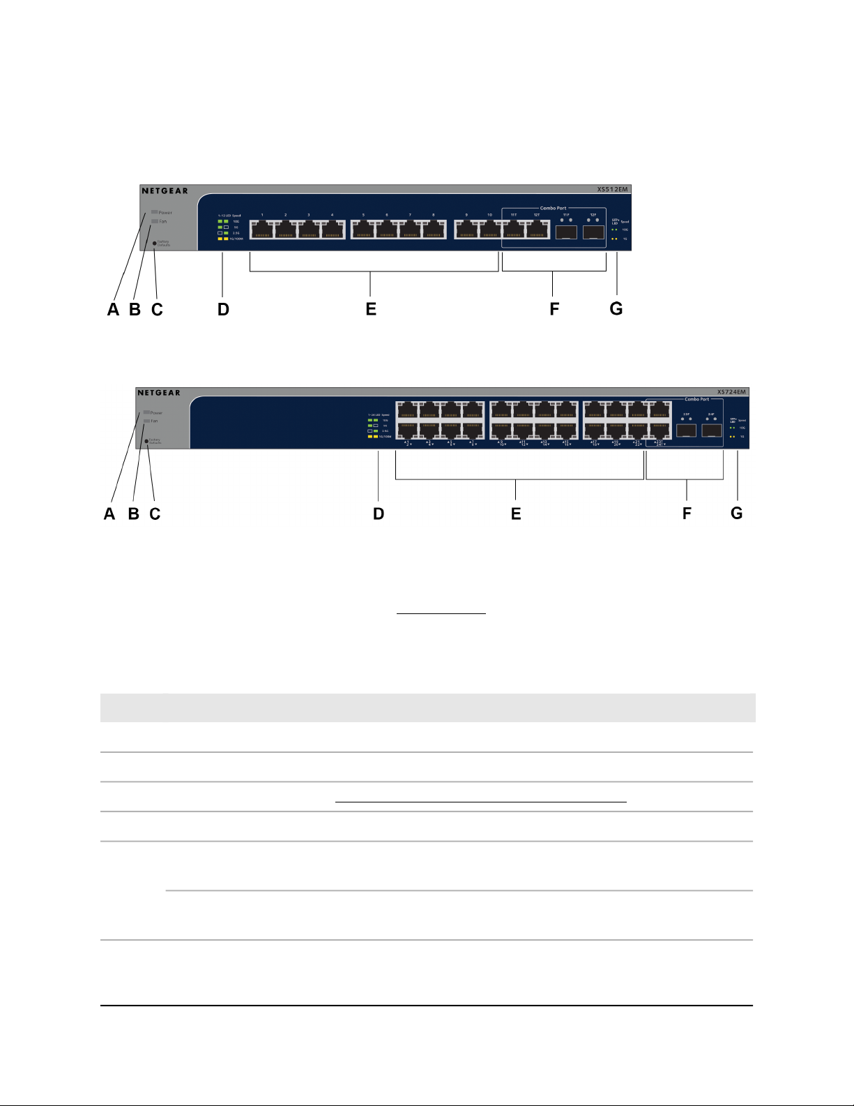
Front Panel
Figure 1. Front panel model XS512EM
Figure 2. Front panel model XS724EM
The following table lists the front panel components from left to right. For detailed
information about the status LEDs, see Status LEDs on page 9.
Table 1. Front panel components
DescriptionLetter
Power LED.A
Fan LED.B
Factory Defaults button (see Use the Factory Defaults Button to Reset the Switch on page 71).C
Ethernet port LED descriptions (printed on the front panel).D
E
Model XS512EM. Ten RJ-45 10-Gig/Multi-Gig Ethernet ports numbered 1 through 10 that support
10G, 5G, 2.5G, 1G, and 100M and that provide two Ethernet port LEDs each.
Model XS724EM. Twenty-two RJ-45 10-Gig/Multi-Gig Ethernet ports numbered 1 through 22 that
support 10G, 5G, 2.5G, 1G, and 100M and that provide two Ethernet port LEDs each.
Switch
User Manual8Hardware Overview of the
Page 9
12- or 24-Port 10-Gigabit/Multi-Gigabit Smart Managed Plus Switch Models XS512EM and XS724EM
Table 1. Front panel components (Continued)
DescriptionLetter
F
Model XS512EM. Two combo ports. You can use either ports 11T and 12T as 10-Gig/Multi-Gig Ethernet
ports for 10G, 5G, 2.5G, 1G, and 100M connectivity or ports 11F and 12F as SFP+ slots for optional
fiber or copper transceiver modules.
Ports 11T and 12T provide two Ethernet port LEDs each. Ports 11F and 12F provide two SFP+ slot
LEDS each. For information about the supported transceiver modules, see SFP Slots for Fiber or Copper
Connectivity on page 11.
Model XS724EM. Two combo ports. You can use either ports 23T and 24T as 10-Gig/Multi-Gig Ethernet
ports for 10G, 5G, 2.5G, 1G, and 100M connectivity or ports 23F and 24F as SFP+ slots for optional
fiber or copper transceiver modules.
Ports 23T and 24T provide two Ethernet port LEDs each. Slots 23F and 24F provide two SFP+ slot LEDS
each. For information about the supported transceiver modules, see SFP Slots for Fiber or Copper
Connectivity on page 11.
SFP+ slot LED descriptions (printed on the front panel).G
Status LEDs
Status LEDs are located on the front panel of the switch. Each port and slot provides a
left LED and a right LED that, in combination, indicate speed and activity.
Table 2. LED descriptions
LED
Power LED
Fan LED
Left
LED
N/A (single
LED only)
N/A (single
LED only)
DescriptionRight
LED
Off. No power is supplied to the switch.
Solid green. Power is supplied to the switch and the switch is ready for
operation.
Off. The fan is operating normally.
Solid yellow. A fan failure occurred.
Switch
User Manual9Hardware Overview of the
Page 10
12- or 24-Port 10-Gigabit/Multi-Gigabit Smart Managed Plus Switch Models XS512EM and XS724EM
Table 2. LED descriptions (Continued)
LED
Model XS512EM:
LEDs for ports 1
through 10 and
combo ports 11T
and 12T
Model XS724EM:
LEDs for ports 1
through 22 and
combo ports 23T
and 24T
Model XS512EM:
LEDs for ports 11F
and 12F
Model XS724EM:
LEDs for ports 23F
and 24F
Left
LED
LED
GreenGreenEthernet port LEDs
OffGreen
GreenOff
YellowYellow
GreenGreenSFP+ slot LEDs
YellowYellow
DescriptionRight
Both LEDs solid green. A 10G link with a powered-on device is detected.
Both LEDs blinking green. Traffic is detected on the 10G link.
Left LED solid green, right LED off. A 5G link with a powered-on device
is detected.
Left LED blinking green, right LED off. Traffic is detected on the 5G link.
Left LED off, right LED solid green. A 2.5G link with a powered-on device
is detected.
Left LED off, right LED blinking green. Traffic is detected on the 2.5G
link.
Both LEDs solid yellow. A 1G or 100M link with a powered-on device is
detected.
Both LEDs blinking yellow. Traffic is detected on the 1G or 100M link.
No link with a powered-on device is detected.OffOff
Both LEDs solid green. A 10G link with a powered-on device is detected.
Both LEDs blinking green. Traffic is detected on the 10G link.
Both LEDs solid yellow. A 1G link with a powered-on device is detected.
Both LEDs blinking yellow. Traffic is detected on the 1G link.
No link with a powered-on device is detected.OffOff
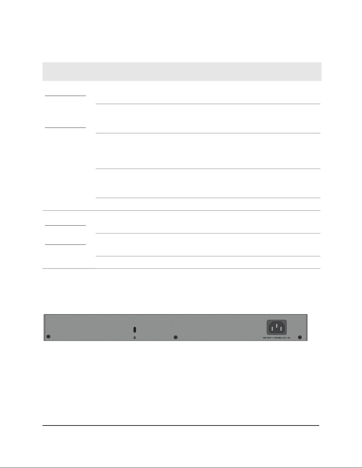
Back Panel
Figure 3. Back panel
The back panel of the switch provides a Kensington lock slot for an optional lock and
the AC power connector for the power cable.
The previous figure shows the back panel of model XS724EM. The back panel of model
XS512EM contains the same components.
User Manual10Hardware Overview of the
Switch
Page 11
12- or 24-Port 10-Gigabit/Multi-Gigabit Smart Managed Plus Switch Models XS512EM and XS724EM
SFP Slots for Fiber or Copper Connectivity
To enable fiber connections and additional copper (Ethernet) connections on the switch,
SFP+ slots accommodate standard small form-factor pluggable (SFP) gigabit interface
converters (GBICs, also referred to as transceiver modules). GBICs are sold separately
from the switch.
On model XS512EM, you can insert transceiver modules in slots 11F and 12F, in which
case you cannot use ports 11T and 12T.
On model XS512EM, you can insert transceiver modules in slots 23F and 24F, in which
case you cannot use ports 23T and 24T.
These models support the NETGEAR SFP transceiver modules and direct-attach cables
(DACs) that are listed in the following table.
Table 3. Supported SFP and SFP+ transceiver modules and DACs
DescriptionModelSpeed and Medium
SFP transceiver 1000BASE-SXAGM731F1G Ethernet short-reach fiber
SFP transceiver 1000BASE-LXAGM732F1G Ethernet long-range fiber
SFP transceiver 1000BASE-TAGM7341G Ethernet copper
SFP+ transceiver 10GBASE-SR multimodeAXM76110GBASE short-reach fiber
AXM76210GBASE long-range fiber
AXM76310GBASE long-range fiber
AXM76410GBASE long-range fiber lite
SFP+ transceiver 10GBASE-LR single
mode
SFP+ transceiver 10GBASE-LRM
multimode
SFP+ transceiver 10GBASE-LR Lite single
mode
SFP+ XFP DAC, 3-meter DACAXC75310G Ethernet copper
SFP+ DAC cable, 1-meter DACAXC76110G Ethernet copper
SFP+ DAC cable, 3-meter DACAXC76310G Ethernet copper
For more information about NETGEAR ProSAFE SFP and SFP+ transceiver modules and
cables, visit netgear.com/business/products/switches/modules-accessories.
Switch
User Manual11Hardware Overview of the
Page 12
12- or 24-Port 10-Gigabit/Multi-Gigabit Smart Managed Plus Switch Models XS512EM and XS724EM
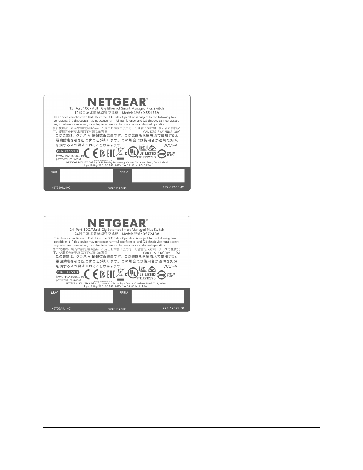
Switch Label
The label on the bottom panel of the switch shows the serial number, MAC address,
default login information, and other information for the switch.
Figure 4. Switch label model XS512EM
Figure 5. Switch label model XS724EM
Safety Instructions and Warnings
Use the following safety guidelines to ensure your own personal safety and to help
protect your system from potential damage.
User Manual12Hardware Overview of the
Switch
Page 13

12- or 24-Port 10-Gigabit/Multi-Gigabit Smart Managed Plus Switch Models XS512EM and XS724EM
To reduce the risk of bodily injury, electrical shock, fire, and damage to the equipment,
observe the following precautions:
This product is designed for indoor use only in a temperature-controlled and
•
humidity-controlled environment. For more information, see the environmental
specifications in the appendix or the data sheet.
Any device that is located outdoors and connected to this product must be properly
grounded and surge protected.
Failure to follow these guidelines can result in damage to your NETGEAR product,
which might not be covered by NETGEAR’s warranty, to the extent permissible by
applicable law.
Observe and follow service markings:
•
- Do not service any product except as explained in your system documentation.
Some devices should never be opened.
-
If applicable to your device, opening or removing covers that are marked with
the triangular symbol with a lightning bolt can expose you to electrical shock.
We recommend that only a trained technician services components inside these
compartments.
If any of the following conditions occur, unplug the product from the electrical outlet
•
and replace the part or contact your trained service provider:
- Depending on your device, the power adapter, power adapter cable, power
cable, extension cable, or plug is damaged.
-
An object fell into the product.
- The product was exposed to water.
- The product was dropped or damaged.
-
The product does not operate correctly when you follow the operating
instructions.
Keep your system away from radiators and heat sources. Also, do not block cooling
•
vents.
Do not spill food or liquids on your system components, and never operate the
•
product in a wet environment. If the system gets wet, see the appropriate section in
your troubleshooting guide, or contact your trained service provider.
Do not push any objects into the openings of your system. Doing so can cause fire
•
or electric shock by shorting out interior components.
Use the product only with approved equipment.
•
If applicable to your device, allow the product to cool before removing covers or
•
touching internal components.
User Manual13Hardware Overview of the
Switch
Page 14

12- or 24-Port 10-Gigabit/Multi-Gigabit Smart Managed Plus Switch Models XS512EM and XS724EM
Operate the product only from the type of external power source indicated on the
•
electrical ratings label. If you are not sure of the type of power source required,
consult your service provider or local power company.
To avoid damaging your system, if your device uses a power supply with a voltage
•
selector, be sure that the selector is set to match the power at your location:
-
115V, 60 Hz in most of North and South America and some Far Eastern countries
such as South Korea and Taiwan
- 100V, 50 Hz in eastern Japan and 100V, 60 Hz in western Japan
-
230V, 50 Hz in most of Europe, the Middle East, and the Far East
Be sure that attached devices are electrically rated to operate with the power available
•
in your location.
Depending on your device, use only a supplied power adapter or approved power
•
cable:
If your device uses a power adapter:
-
If you were not provided with a power adapter, contact your local NETGEAR
reseller.
-
The power adapter must be rated for the product and for the voltage and current
marked on the product electrical ratings label.
If your device uses a power cable:
-
If you were not provided with a power cable for your system or for any
AC-powered option intended for your system, purchase a power cable approved
for your country.
-
The power cable must be rated for the product and for the voltage and current
marked on the product electrical ratings label. The voltage and current rating of
the cable must be greater than the ratings marked on the product.
To help prevent electric shock, plug the system and peripheral power cables into
•
properly grounded electrical outlets.
If applicable to your device, the peripheral power cables are equipped with
•
three-prong plugs to help ensure proper grounding. Do not use adapter plugs or
remove the grounding prong from a cable. If you must use an extension cable, use
a three-wire cable with properly grounded plugs.
Observe extension cable and power strip ratings. Make sure that the total ampere
•
rating of all products plugged into the extension cable or power strip does not
exceed 80 percent of the ampere ratings limit for the extension cable or power strip.
User Manual14Hardware Overview of the
Switch
Page 15

12- or 24-Port 10-Gigabit/Multi-Gigabit Smart Managed Plus Switch Models XS512EM and XS724EM
To help protect your system from sudden, transient increases and decreases in
•
electrical power, use a surge suppressor, line conditioner, or uninterruptible power
supply (UPS).
Position system cables, power adapter cables, or power cables carefully. Route
•
cables so that they cannot be stepped on or tripped over. Be sure that nothing rests
on any cables.
Do not modify power adapters, power adapter cables, power cables or plugs. Consult
•
a licensed electrician or your power company for site modifications.
Always follow your local and national wiring rules.
•
Switch
User Manual15Hardware Overview of the
Page 16

2
Install and Access the Switch in Your Network
This chapter describes how you can install and access the switch in your network.
The chapter contains the following sections:
• Ethernet Cables and Speeds
• Install the Switch in Your Network
• Methods to Discover and Access the Switch
• Access the Switch and Discover the IP Address of the Switch
• Set Up a Fixed IP Address for the Switch
• Use the NETGEAR Insight Mobile App to Access the Switch
• Use the NETGEAR ProSAFE Plus Utility to Access the Switch
• Change the Switch Password
• Register Your Product
16
Page 17
12- or 24-Port 10-Gigabit/Multi-Gigabit Smart Managed Plus Switch Models XS512EM and XS724EM
Ethernet Cables and Speeds
Before you set up the switch in your network, review the information in the following
table, which describes the cables that you can use for the switch connections and the
speeds that these cables can support, up to 100 meters (328 feet).
Table 4. Ethernet cables and speeds
Ethernet Cable TypeSpeed
Category 5 (Cat 5) or higher rated100 Mbps
Category 5e (Cat 5e) or higher rated1 Gbps, 2.5 Gbps, or 5 Gbps
Category 6 (Cat 6) or higher rated10 Gbps, up to 55 meters (180 feet)
Category 6A (Cat 6A) or higher rated10 Gbps, more than 55 meters (180 feet)
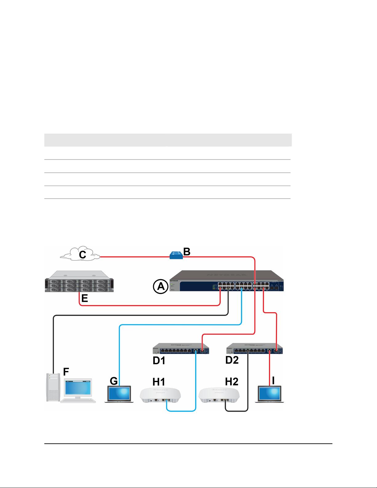
Install the Switch in Your Network
Figure 6. Sample connections
Your Network
User Manual17Install and Access the Switch in
Page 18
12- or 24-Port 10-Gigabit/Multi-Gigabit Smart Managed Plus Switch Models XS512EM and XS724EM
Table 5. Figure components
DescriptionLetterDescriptionLetter
A
model is shown in the previous figure)
D1 and
D2
Cable colors: Red is a 10G connection, blue is a 2.5G connection, and black is a 1G connection.
figure shows two NETGEAR GS110EMX
switches)
1G computerFXS512EM or XS724EM switch (the latter
2.5G gaming computerGNetwork router that support 10GB
2.5G WiFi access pointH1Internet connection that support 10GC
1G WiFi access pointH2Edge switches that support 10G (the
Computer with a 10G Thunderbolt portI10G NAS deviceE
Ports 1 through 10 on model XS512EM and ports 1 through 22 on model XS724EM
(which is shown in the previous figure) support 10G, 5G, 2.5G, 1G, and 100M.
On model XS512EM, ports 11T and 11F form one combo port and ports 12T and 12F
form another combo port. On model XS724EM, ports 23T and 23F form one combo
port and ports 24T and 24F form another combo port. For these combo ports, you can
use either the copper port (that is, the T port) or the fiber port (that is, the F port), but
not both at the same time. The combo ports support 10G and 1G. For Ethernet
connections, use the cables that we recommend in the previous table. For SFP slot
connections, see SFP Slots for Fiber or Copper Connectivity on page 11.
This section describes how you can set up in the switch in either a business network or
a small office or home office network.
User Manual18Install and Access the Switch in
Your Network
Page 19

12- or 24-Port 10-Gigabit/Multi-Gigabit Smart Managed Plus Switch Models XS512EM and XS724EM
To set up the switch in your network and power on the switch:
1.
Depending on nature and size of your network, do the following:
Business network. Connect one RJ-45 port (or a transceiver module in an SFP
•
slot) on the switch (A in the previous figure) to a network router (B) that is directly
connected to the Internet (C). This network setup is shown in the previous figure.
Small office or home office network. Connect one RJ-45 port on the switch to
•
either the LAN port on your router that is connected to your Internet modem or
directly to your Internet modem.
Note: The switch can provide 10G speeds only if your Internet connection supports
10G. Depending on your setup, if your router, Internet modem, or both do support
10G speeds, connect one RJ-45 port on the switch to your router or your Internet
modem.
2. Connect devices to the RJ-45 network ports (or transceiver modules in SFP slots) on
the switch (A).
The following sample connections are shown in the previous figure:
(As described in the previous step) 10G link to a network router (B) that is directly
•
connected to the Internet (C)
10G links to edge switches (D1 and D2)
•
10G link to a 10G network-attached storage (NAS) device (E)
•
1G link to a computer (F)
•
2.5G link to a high-speed gaming computer (G)
•
3. Connect devices to the edge switches (D1 and D2).
The following sample connections are shown in the previous figure:
2.5G link to a WiFi access point (H1)
•
1G link to a WiFi access point (H2)
•
10G link to a computer with a Thunderbolt port
•
4. Turn on the switch by connecting the power cable to the switch and plugging the
power cable into an electrical outlet.
The green Power LED at the front of the switch lights and the port LEDs for connected
devices light.
User Manual19Install and Access the Switch in
Your Network
Page 20

12- or 24-Port 10-Gigabit/Multi-Gigabit Smart Managed Plus Switch Models XS512EM and XS724EM
Methods to Discover and Access the Switch
You can use any of the following methods to discover the switch in your network and
access the switch to configure and manage it:
Computer and web browser. Use a computer and a web browser to discover the
•
switch in your network and access the local browser interface of the switch (see
Access the Switch and Discover the IP Address of the Switch on page 20 or Set Up
a Fixed IP Address for the Switch on page 23).
Insight mobile app. Install the NETGEAR Insight mobile app on a smartphone or
•
tablet to discover the switch in your network and access the local browser interface
of the switch (see Use the NETGEAR Insight Mobile App to Access the Switch on
page 27).
ProSAFE Plus Utility. Install the NETGEAR ProSAFE®Plus Utility on a Windows-based
•
computer and use the utility to discover the switch in your network and perform
basic configurations (see Use the NETGEAR ProSAFE Plus Utility to Access the Switch
on page 28).
Access the Switch and Discover the IP Address of the Switch
By default, the switch receives an IP address from a DHCP server (or a router that
functions as a DHCP server) in your network.
For information about setting up a fixed (static) IP address on the switch, see Set Up a
Fixed IP Address for the Switch on page 23.
Access the Switch From a Windows-Based Computer
To access the switch from a Windows-based computer and discover the switch IP
address:
1. Open Windows Explorer or File Explorer.
2.
Click the Network link.
3.
If prompted, enable the Network Discovery feature.
4.
Under Network Infrastructure, locate the XS512EM switch or the XS724EM switch.
5.
Double-click XS512EM (xx:xx:xx:xx:xx:xx) or XS724EM (xx:xx:xx:xx:xx:xx), in
which xx:xx:xx:xx:xx:xx is the MAC address of the switch.
The login page of the local browser interface opens.
User Manual20Install and Access the Switch in
Your Network
Page 21

12- or 24-Port 10-Gigabit/Multi-Gigabit Smart Managed Plus Switch Models XS512EM and XS724EM
6. Enter the switch password.
The default password is password. The password is case-sensitive.
The Switch Information page displays. The page shows the IP address that is assigned
to the switch.
Tip: You can copy and paste the IP address into a new shortcut or bookmark it for
quick access on your computer or mobile device. However, if you restart the switch,
a dynamic IP address (assigned by a DHCP server) might change and the bookmark
might no longer link to the login page for the switch. In that situation, you must
repeat this procedure so that you can discover the new IP address of the switch in
the network and update your bookmark accordingly. You can also set up a fixed
(static) IP address for the switch (see Set Up a Fixed IP Address for the Switch on
page 23) to make sure that the new bookmark always links to the login page for the
switch, even after you restart the switch.
Access the Switch From a Mac Using Bonjour
If your Mac supports Bonjour, you can use the following procedure. If your Mac does
not support Bonjour, see Access the Switch From a Mac or Windows-Based Computer
Using the NETGEAR Switch Discovery Tool on page 22.
To access the switch from a Mac using Bonjour and discover the switch IP address:
1.
Open the Safari browser.
2.
Select Safari > Preferences.
The General page displays.
3.
Click the Advanced tab.
The Advanced page displays.
4.
Select the Include Bonjour in the Bookmarks Menu check box.
5. Close the Advanced page.
6.
Depending on your Mac OS version, select one of the following, in which
xx:xx:xx:xx:xx:xx is the MAC address of the switch:
Bookmarks > Bonjour > XS512EM (xx:xx:xx:xx:xx:xx) or XS724EM
•
(xx:xx:xx:xx:xx:xx)
Bookmarks > Bonjour > Webpages XS512EM (xx:xx:xx:xx:xx:xx) or
•
Webpages XS724EM (xx:xx:xx:xx:xx:xx)
The login page of the local browser interface opens.
Your Network
User Manual21Install and Access the Switch in
Page 22

12- or 24-Port 10-Gigabit/Multi-Gigabit Smart Managed Plus Switch Models XS512EM and XS724EM
7. Enter the switch password.
The default password is password. The password is case-sensitive.
The Switch Information page displays. The page shows the IP address that is assigned
to the switch.
Tip: You can copy and paste the IP address into a new shortcut or bookmark it for
quick access on your computer or mobile device. However, if you restart the switch,
a dynamic IP address (assigned by a DHCP server) might change and the bookmark
might no longer link to the login page for the switch. In that situation, you must
repeat this procedure so that you can discover the new IP address of the switch in
the network and update your bookmark accordingly. You can also set up a fixed
(static) IP address for the switch (see Set Up a Fixed IP Address for the Switch on
page 23) to make sure that the new bookmark always links to the login page for the
switch, even after you restart the switch.
Access the Switch From a Mac or Windows-Based Computer Using the NETGEAR Switch Discovery Tool
The NETGEAR Switch Discovery Tool lets you discover the switch in your network and
access the local browser interface of the switch from a Mac or a 64-bit Windows-based
computer. If your Mac does not support Bonjour, use the following procedure.
To install the NETGEAR Switch Discovery Tool, discover the switch in your network,
access the switch, and discover the switch IP address:
1. Download the Switch Discovery Tool by visiting
netgear.com/support/product/xs724em.aspx#download.
Depending on the computer that you are using, download either the Mac version
or the version for a 64-bit Windows-based computer.
2.
Temporarily disable the firewall, Internet security, antivirus programs, or all of these
on the computer that you use to configure the switch.
3.
Unzip the Switch Discovery Tool files, double-click the .exe or .dmg file (for example,
NETGEAR+Switch+Discovery+Tool+Setup+1.2.101.exe or
NetgearSDT-V1.2.101.dmg), and install the program on your computer.
Depending on your computer setup, the installation process might add the NETGEAR
Switch Discovery Tool icon to the Dock of your Mac or the desktop of your
Windows-based computer.
4. Reenable the security services on your computer.
5. Power on the switch.
The DHCP server assigns the switch an IP address.
Your Network
User Manual22Install and Access the Switch in
Page 23

12- or 24-Port 10-Gigabit/Multi-Gigabit Smart Managed Plus Switch Models XS512EM and XS724EM
6. Connect your computer to the same network as the switch.
You can use a WiFi or wired connection. The computer and the switch must be on
the same Layer 2 network.
7. Open the Switch Discovery Tool.
If the NETGEAR Switch Discovery Tool icon is in the Dock of your Mac or on the
desktop of your Windows-based computer, click or double-click the NETGEAR
Switch Discovery Tool icon to open the program.
The initial page displays a menu and a button.
8.
From the Choose a connection menu, select the network connection that allows
the Switch Discovery Tool to access the switch.
9.
Click the Start Searching button.
The Switch Discovery Tool displays a list of Smart Managed Plus Switches that it
discovers on the selected network.
For each switch, the tool displays the IP address.
10.
To access the local browser interface of the switch, click the ADMIN PAGE button.
The login page of the local browser interface opens.
11. Enter the switch password.
The default password is password. The password is case-sensitive.
The Switch Information page displays. The page shows the IP address that is assigned
to the switch.
Tip: You can copy and paste the IP address into a new shortcut or bookmark it for
quick access on your computer or mobile device. However, if you restart the switch,
a dynamic IP address (assigned by a DHCP server) might change and the bookmark
might no longer link to the login page for the switch. In that situation, you must
repeat this procedure so that you can discover the new IP address of the switch in
the network and update your bookmark accordingly. You can also set up a fixed
(static) IP address for the switch (see Set Up a Fixed IP Address for the Switch on
page 23) to make sure that the new bookmark always links to the login page for the
switch, even after you restart the switch.
Set Up a Fixed IP Address for the Switch
By default, the switch receives an IP address from a DHCP server (or a router that
functions as a DHCP server) in your network. However, the DHCP server might not always
User Manual23Install and Access the Switch in
Your Network
Page 24

12- or 24-Port 10-Gigabit/Multi-Gigabit Smart Managed Plus Switch Models XS512EM and XS724EM
issue the same IP address to the switch. For easy access to the switch local browser
interface, you can set up a fixed (static) IP address on the switch. This allows you to
manage the switch anytime from a mobile device because the switch IP address remains
the same.
To change the IP address of the switch, you can connect to the switch by one of the
following methods:
Through a network connection. If the switch and your computer are connected to
•
the same network (which is the most likely situation), you can change the IP address
of the switch through a network connection (see Set Up a Fixed IP Address for the
Switch Through a Network Connection on page 24).
Through a direct connection. In the unlikely situation that the switch is not connected
•
to a network, or for some reason you cannot connect to the switch over a network
connection, you can change the IP address of the switch by using an Ethernet cable
and making a direct connection to the switch (see Set Up a Fixed IP Address for the
Switch by Connecting Directly to the Switch Off-Network on page 25).
Set Up a Fixed IP Address for the Switch Through a Network Connection
If the switch and your computer are connected to the same network (which is the most
the likely situation), you can change the IP address of the switch through a network
connection.
To disable the DHCP client of the switch and change the IP address of the switch
to a fixed IP address by using a network connection:
1. Connect your computer to the same network as the switch.
You can use a WiFi or wired network connection.
2. Launch a web browser.
3.
In the address field of your web browser, enter the IP address of the switch.
The login page displays.
4. Enter the switch password.
The default password is password. The password is case-sensitive.
The Switch Information page displays.
5.
From the DHCP Mode menu, select Disable.
The IP address fields become available.
6.
Enter the fixed (static) IP address that you want to assign to the switch and the
associated subnet mask and gateway IP address.
Your Network
User Manual24Install and Access the Switch in
Page 25

12- or 24-Port 10-Gigabit/Multi-Gigabit Smart Managed Plus Switch Models XS512EM and XS724EM
You can also either leave the address in the IP Address field as it is (with the IP
address that was issued by the DHCP server) or change the last three digits of the
IP address to an unused IP address.
7.
Write down the complete fixed IP address.
You can bookmark it later.
8.
Click the Apply button.
Your settings are saved. Your switch web session is disconnected when you change
the IP address.
9.
If the login page does not display, in the address field of your web browser, enter
the new IP address of the switch.
The login page displays.
10.
For easy access to the local browser interface, bookmark the page on your computer.
Set Up a Fixed IP Address for the Switch by Connecting Directly to the Switch Off-Network
In the unlikely situation that the switch is not connected to a network, or for some reason
you cannot connect to the switch over a network connection, you can change the IP
address of the switch by using an Ethernet cable and making a direct connection to the
switch.
To disable the DHCP client of the switch and change the IP address of the switch
to a fixed IP address by using a direct connection:
1.
Connect an Ethernet cable from your computer to an Ethernet port on the switch.
2.
Change the IP address of your computer to be in the same subnet as the default IP
address of the switch.
The default IP address of the switch is 192.168.0.239. This means that you must
change the IP address of the computer to be on the same subnet as the default IP
address of the switch (192.168.0.x).
The method to change the IP address on your computer depends on the operating
system of your computer.
3.
Open a web browser from a computer that is connected to the switch directly through
an Ethernet cable.
4.
Enter 192.168.0.239 as the IP address of the switch.
The login page displays.
5. Enter the switch password.
Your Network
User Manual25Install and Access the Switch in
Page 26

12- or 24-Port 10-Gigabit/Multi-Gigabit Smart Managed Plus Switch Models XS512EM and XS724EM
The default password is password. The password is case-sensitive.
The Switch Information page displays.
6.
From the DHCP Mode menu, select Disable.
The IP address fields become available.
7.
Enter the fixed (static) IP address that you want to assign to the switch and the
associated subnet mask and gateway IP address.
8.
Write down the complete fixed IP address.
You can bookmark it later.
9.
Click the Apply button.
Your settings are saved. Your switch web session is disconnected when you change
the IP address.
10.
Disconnect the switch from your computer and install the switch in your network.
For more information, see Install the Switch in Your Network on page 17.
11. Restore your computer to its original IP address.
12.
Verify that you can connect to the switch with its new IP address:
a. Connect your computer to the same network as the switch.
You can use a WiFi or wired network connection.
b. Launch a web browser.
c.
In the address field of your web browser, enter the new IP address of the switch.
The login page displays.
d. Enter the switch password.
The default password is password. The password is case-sensitive.
The Switch Information page displays.
Your Network
User Manual26Install and Access the Switch in
Page 27

12- or 24-Port 10-Gigabit/Multi-Gigabit Smart Managed Plus Switch Models XS512EM and XS724EM
Use the NETGEAR Insight Mobile App to Access the Switch
The NETGEAR Insight mobile app lets you discover the switch in your network and
access the local browser interface of the switch from your smartphone.
To access the switch from the Insight app:
1.
On your iOS or Android mobile device, go to the app store, search for NETGEAR
Insight, and download and install the app.
2.
If the switch is directly connected to a WiFi router or access point, connect your
mobile device to the WiFi network of the router or access point.
3.
Select LOG IN to log in to your existing NETGEAR account or tap the CREATE
NETGEAR ACCOUNT button to create a new account.
4.
After you log in to your account, name your network and specify a device admin
password that applies to all devices that you add to this network, and tap the NEXT
button.
5.
You can now add a device. Choose one of the following options:
Add a device by scanning your network.
•
Add a device by entering its serial number.
•
Add a device by scanning its barcode.
•
Note: Pages might display and suggest that you connect the switch to power and
to an uplink. If you already did this, on these pages, tap the NEXT button.
6.
If the switch is not yet connected to the same WiFi network as your mobile device,
connect it now to the same WiFi network, wait two minutes, and then tap the NEXT
button.
The switch is discovered and registered on the network.
7.
In the Insight app, select the switch and tap the Visit Web Interface link.
The login page of the local browser interface opens.
8. Enter the switch password.
The default password is password. The password is case-sensitive.
The Switch Information page displays.
Your Network
User Manual27Install and Access the Switch in
Page 28

12- or 24-Port 10-Gigabit/Multi-Gigabit Smart Managed Plus Switch Models XS512EM and XS724EM
Use the NETGEAR ProSAFE Plus Utility to Access the Switch
The NETGEAR ProSAFE Plus Utility runs on Windows-based computers and lets you
customize and manage the switch for your network. For easiest access, we recommend
that you cable the switch to a network with a router or DHCP server that assigns IP
addresses, power on the switch, and then use a computer that is connected to the same
network as the switch.
Note: The ProSAFE Plus Utility requires WinPcap and Adobe Air. If WinPcap and Adobe
Air are not detected during the ProSAFE Plus Utility installation, you are prompted to
allow them to be installed.
To install the ProSAFE Plus Utility and access and configure the switch:
1. Download the ProSAFE Plus Utility by visiting netgear.com/support/product/PCU.
You must use ProSAFE Plus Utility version 2.5.3 or a later version.
2.
Temporarily disable the firewall, Internet security, antivirus programs, or all of these
on the computer that you use to configure the switch.
Note: Instead of disabling security services, you can also configure your computer’s
security software to allow broadcast UDP packets to go through UDP remote and
source (local and destination) ports 63321 through 63324. To allow this traffic, you
can create a rule in your computer’s security software.
3.
Unzip the ProSAFE Plus Utility files, double-click the .exe file (for example, ProSAFE
Plus Utility 2.5.3.exe), and install the program on your computer.
The installation process places a ProSAFE Plus Utility icon on your desktop.
4.
If you temporarily disabled any security services, reenable those services.
Note: We recommend that you restart your computer after installing the ProSAFE
Plus Utility.
5. Power on the switch.
The DHCP server assigns the switch an IP address.
6. Connect your computer to the same network as the switch.
You can use a WiFi or wired connection. The computer and the switch must be on
the same Layer 2 network.
User Manual28Install and Access the Switch in
Your Network
Page 29

12- or 24-Port 10-Gigabit/Multi-Gigabit Smart Managed Plus Switch Models XS512EM and XS724EM
7. Open the ProSAFE Plus Utility.
To open the program, double-click the ProSAFE Plus Utility icon on your desktop.
The discovery process initiates and completes automatically and the configuration
home page displays a list of Smart Managed Plus switches that the utility discovers
on the local network.
8. Select the switch.
If you do not see the switch, click the REFRESH button.
9.
Click the APPLY button.
The login window displays.
10. Enter the switch password.
The default password is password. The password is case-sensitive.
The Switch Status page display.
11.
Use the utility to configure the switch settings.
For a description of ProSAFE Plus Utility features, see the ProSAFE Plus Utility User
Manual. You can access the user manual through links on the Help tab of the utility,
or you can download it by visiting netgear.com/support/download/.
Change the Switch Password
The default password to access the switch is password. We recommend that you change
this password to a more secure password. The ideal password contains no dictionary
words from any language and contains uppercase and lowercase letters, numbers, and
symbols. It can be up to 20 characters.
To change the password:
1. Connect your computer to the same network as the switch.
You can use a WiFi or wired network connection, or connect directly to a switch that
is off-network using an Ethernet cable.
2. Launch a web browser.
3.
In the address field of your web browser, enter the IP address of the switch.
The login page displays.
4. Enter the switch password.
The default password is password. The password is case-sensitive.
Your Network
User Manual29Install and Access the Switch in
Page 30

12- or 24-Port 10-Gigabit/Multi-Gigabit Smart Managed Plus Switch Models XS512EM and XS724EM
The Switch Information page displays.
5.
Select Maintenance > Change Password.
The Change Password page displays.
6.
In the Old Password field, type the current password for the switch.
7.
Type the new password in the New Password field and in the Re-type New
Password field.
8.
Click the Apply button.
Your settings are saved. Keep the new password in a secure location so that you can
access the switch in the future.
Register Your Product
We recommend that you use the NETGEAR Insight mobile app to register your product
(see Use the NETGEAR Insight Mobile App to Access the Switch on page 27).
Registering your product allows you to receive email alerts and streamlines the technical
support process. However, you can also register your product through the local browser
interface.
To register your product through the local browser interface:
1. Connect your computer to the same network as the switch.
You can use a WiFi or wired network connection.
Note: You must access the switch while connected to the network (on-network) to
register the switch.
2. Launch a web browser.
3.
In the address field of your web browser, enter the IP address of the switch.
The login page displays.
4. Enter the switch password.
The default password is password. The password is case-sensitive.
The Switch Information page displays.
5.
Select Help > Registration.
The Product Registration page displays.
6.
Click the Register button.
Your Network
User Manual30Install and Access the Switch in
Page 31

12- or 24-Port 10-Gigabit/Multi-Gigabit Smart Managed Plus Switch Models XS512EM and XS724EM
7. Follow the onscreen process to register your product.
Your Network
User Manual31Install and Access the Switch in
Page 32

3
Use VLANS for Traffic Segmentation
This chapter describes how you can use VLANs to segment traffic on the switch.
The chapter contains the following sections:
• VLAN Overview
• Create Basic Port-Based VLANs
• Assign Ports to Multiple Port-Based VLANs
• Create 802.1Q-Based VLANs in a Basic Configuration
• Create 802.1Q-Based VLANs in an Advanced Configuration
• Add Tagged or Untagged Ports to an 802.1Q-Based VLAN
• Specify a Port PVID for an 802.1Q-Based VLAN
• Manage the Voice VLAN
32
Page 33

12- or 24-Port 10-Gigabit/Multi-Gigabit Smart Managed Plus Switch Models XS512EM and XS724EM
VLAN Overview
Virtual LANs (VLANs) are made up of networked devices that are grouped logically into
separate networks. You can group ports on a switch to create a virtual network made
up of the devices connected to the ports.
Ports can be grouped in VLANs using port-based or 802.1Q criteria:
Port-based VLANs. Assign ports to virtual networks. Ports with the same VLAN ID
•
are placed in the same VLAN. This feature provides an easy way to partition a network
into private subnetworks.
802.1Q VLANs. Create virtual networks using the IEEE 802.1Q standard. 802.1Q
•
uses a VLAN tagging system to determine which VLAN an Ethernet frame belongs
to. You can configure ports to be a part of a VLAN. When a port receives data tagged
for a VLAN, the data is discarded unless the port is a member of that VLAN. This
technique is useful for communicating with devices outside your local network as
well as receiving data from other ports that are not in the VLAN. However, for you
to be able to use an 802.1Q VLAN, you must know the VLAN ID.
Create Basic Port-Based VLANs
A port-based VLAN configuration lets you assign ports on the switch to a VLAN. The
number of VLANs is limited to the number of ports on the switch. In a basic port-based
VLAN configuration, ports with the same VLAN ID are placed into the same VLAN.
You can also assign ports to multiple VLANs (see Assign Ports to Multiple Port-Based
VLANs on page 34).
By default, all ports are members of VLAN 1.
To create basic port-based VLANs:
1. Connect your computer to the same network as the switch.
You can use a WiFi or wired network connection, or connect directly to a switch that
is off-network using an Ethernet cable.
2. Launch a web browser.
3.
In the address field of your web browser, enter the IP address of the switch.
The login page displays.
4. Enter the switch password.
The default password is password. The password is case-sensitive.
The Switch Information page displays.
Segmentation
User Manual33Use VLANS for Traffic
Page 34

12- or 24-Port 10-Gigabit/Multi-Gigabit Smart Managed Plus Switch Models XS512EM and XS724EM
5.
Select VLAN.
The Basic Port-Based VLAN Status page displays.
6.
If this is the first time that you are accessing this page or if you are changing the
VLAN assignment method, select the Enable radio button and continue with Step
7.
Otherwise, see Step 9.
A pop-up window opens, informing you that the current VLAN settings will be lost.
7.
Click the OK button.
The pop-up window closes.
8.
Click the Apply button.
Your settings are saved.
The Basic Port-Based VLAN Group table displays.
9.
Under each port to be added to a VLAN, enter the ID of the VLAN.
You can enter a VLAN ID from 1 to the maximum number of ports that your switch
supports. If all the VLANs share an uplink to the Internet or servers, enter all in the
VLAN ID field for the port that you want to use for the uplink.
Note: If ports are members of the same LAG, you must assign them to the same
VLAN.
10.
Click the Apply button.
Your settings are saved.
Assign Ports to Multiple Port-Based VLANs
A port-based VLAN configuration lets you assign ports on the switch to a VLAN. The
number of VLANs is limited to the number of ports on the switch. In an advanced
port-based VLAN configuration, you can assign a single port to multiple VLANs.
By default, all ports are members of VLAN 1.
To assign ports to multiple port-based VLANs:
1. Connect your computer to the same network as the switch.
You can use a WiFi or wired network connection, or connect directly to a switch that
is off-network using an Ethernet cable.
2. Launch a web browser.
User Manual34Use VLANS for Traffic
Segmentation
Page 35

12- or 24-Port 10-Gigabit/Multi-Gigabit Smart Managed Plus Switch Models XS512EM and XS724EM
3.
In the address field of your web browser, enter the IP address of the switch.
The login page displays.
4. Enter the switch password.
The default password is password. The password is case-sensitive.
The Switch Information page displays.
5.
Select VLAN.
The Basic Port-Based VLAN Status page displays.
6.
If this is the first time that you are accessing this page or if you are changing the
VLAN assignment method, select the Enable radio button and continue with Step
7.
Otherwise, see Step 9.
A pop-up window opens, informing you that the current VLAN settings will be lost.
7.
Click the OK button.
The pop-up window closes.
8.
Click the Apply button.
Your settings are saved.
The VLAN Configuration and VLAN Membership sections display.
9.
In the VLAN Identifier menu, select the VLAN.
10.
Select the ports that you want to add to the VLAN by doing the following:
a.
(Optional) In the Group Operation menu, select either Select All or Remove
All.
All ports are either added to the VLAN or removed from the VLAN.
b. Select or remove individual ports by selecting the check boxes that are associated
with the port numbers.
Note: If ports are members of the same LAG, you must assign them to the same
VLAN.
c.
Click the Apply button.
Your settings are saved. In the VLAN Membership table, the ports display as
members of the VLAN.
11.
To select ports for another VLAN, repeat Step 9 and Step 10.
Segmentation
User Manual35Use VLANS for Traffic
Page 36

12- or 24-Port 10-Gigabit/Multi-Gigabit Smart Managed Plus Switch Models XS512EM and XS724EM
Create 802.1Q-Based VLANs in a Basic Configuration
A 802.1Q-based VLAN configuration lets you assign ports on the switch to a VLAN with
an ID number in the range of 1–4093. By default, all ports are members of VLAN 1.
In an advanced 802.1Q-based VLAN configuration, you can set up VLANs to which you
can add tagged or untagged ports and you can use port VLAN ID (PVID). For more
information, Create 802.1Q-Based VLANs in an Advanced Configuration on page 37.
To create 802.1Q-based VLANs in a basic configuration:
1. Connect your computer to the same network as the switch.
You can use a WiFi or wired network connection, or connect directly to a switch that
is off-network using an Ethernet cable.
2. Launch a web browser.
3.
In the address field of your web browser, enter the IP address of the switch.
The login page displays.
4. Enter the switch password.
The default password is password. The password is case-sensitive.
The Switch Information page displays.
5.
Select VLAN > 802.1Q.
The Basic 802.1Q VLAN Status page displays.
6.
If this is the first time that you are accessing the Basic 802.1Q VLAN Status page or
if you are changing the VLAN assignment method, select the Enable radio button
and continue with Step 7.
Otherwise, see Step 9.
A pop-up window opens, informing you that the current VLAN settings will be lost.
7.
Click the OK button.
The pop-up window closes.
8.
Click the Apply button.
Your settings are saved.
The Basic 802.1Q VLAN Identifier table displays.
9.
Under each port to be added to a VLAN, enter the ID of the VLAN.
Segmentation
User Manual36Use VLANS for Traffic
Page 37

12- or 24-Port 10-Gigabit/Multi-Gigabit Smart Managed Plus Switch Models XS512EM and XS724EM
You can enter a VLAN ID from 1 to 4093. If all the VLANs share an uplink to the
Internet or servers, enter all in the VLAN ID field for the port that you want to use
for the uplink.
Note: If ports are members of the same LAG, you must assign them to the same
VLAN.
10.
Click the Apply button.
Your settings are saved.
Create 802.1Q-Based VLANs in an Advanced Configuration
In an advanced 802.1Q-based VLAN configuration, you can assign ports on the switch
to a VLAN with an ID number in the range of 1–4093 and you can add tagged or
untagged ports to a VLAN. In addition, you can use port VLAN IDs (PVIDs). By default,
all ports are untagged members of VLAN 1.
To create 802.1Q-based VLANs in an advanced configuration:
1. Connect your computer to the same network as the switch.
You can use a WiFi or wired network connection, or connect directly to a switch that
is off-network using an Ethernet cable.
2. Launch a web browser.
3.
In the address field of your web browser, enter the IP address of the switch.
The login page displays.
4. Enter the switch password.
The default password is password. The password is case-sensitive.
The Switch Information page displays.
5.
Select VLAN > 802.1Q > Advanced > VLAN Configuration.
The Advanced 802.1Q VLAN Status page displays.
6.
If this is the first time that you are accessing the Advanced 802.1Q VLAN Status page
or if you are changing the VLAN assignment method, select the Enable radio button
and continue with Step 7.
Otherwise, see Step 9.
A pop-up window opens, informing you that the current VLAN settings will be lost.
User Manual37Use VLANS for Traffic
Segmentation
Page 38

12- or 24-Port 10-Gigabit/Multi-Gigabit Smart Managed Plus Switch Models XS512EM and XS724EM
7.
Click the OK button.
The pop-up window closes.
8.
Click the Apply button.
Your settings are saved.
The VLAN Identifier Setting table displays.
9.
In the VLAN ID field, enter a VLAN ID.
You can enter a VLAN ID from 1 to 4093.
10.
Click the Add button.
The new VLAN is added to the VLAN Identifier Setting table.
After you create a new VLAN ID, use the VLAN membership option to add ports to
the VLAN. (Select VLAN > 802.1Q > Advanced > VLAN Membership. See also
Add Tagged or Untagged Ports to an 802.1Q-Based VLAN on page 38.)
Note: To delete a VLAN, select the check box for the VLAN and click the Delete
button.
Add Tagged or Untagged Ports to an
802.1Q-Based VLAN
After you define a VLAN ID using the advanced 802.1Q VLAN option (see Create
802.1Q-Based VLANs in an Advanced Configuration on page 37), you must add ports
to the VLAN.
While you add ports to a VLAN, you can specify whether the ports must be tagged or
untagged. Port tagging allows a port to be associated with a particular VLAN and allows
the VLAN ID tag to be added to data packets that are sent through the port. The tag
identifies the VLAN that must receive the data.
By default, all ports are untagged.
To add tagged or untagged ports to an 802.1Q-based VLAN:
1. Connect your computer to the same network as the switch.
You can use a WiFi or wired network connection, or connect directly to a switch that
is off-network using an Ethernet cable.
2. Launch a web browser.
3.
In the address field of your web browser, enter the IP address of the switch.
User Manual38Use VLANS for Traffic
Segmentation
Page 39

12- or 24-Port 10-Gigabit/Multi-Gigabit Smart Managed Plus Switch Models XS512EM and XS724EM
The login page displays.
4. Enter the switch password.
The default password is password. The password is case-sensitive.
The Switch Information page displays.
5.
Select VLAN > 802.1Q > Advanced > VLAN Configuration.
The Advanced 802.1Q VLAN Status page displays. The menu on the left displays
more options.
6.
Select VLAN Membership.
You can select VLAN Membership only if you already enabled the advanced 802.1Q
VLAN option (see Create 802.1Q-Based VLANs in an Advanced Configuration on
page 37).
The VLAN Membership page displays.
7.
In the VLAN ID menu, select the VLAN.
8.
Select the ports that you want to add to the VLAN by doing the following:
a.
(Optional) In the Group Operation menu, select Untag All, Tag all, or Remove
all.
All ports are either added to the VLAN (tagged or untagged) or removed from
the VLAN.
b. Select individual ports and assign them as tagged (T) or untagged (U) ports or
remove individual ports by selecting the check boxes that are associated with
the port numbers.
By default, all ports are untagged.
c.
Click the Apply button.
Your settings are saved. In the VLAN Membership table, the ports display as
members of the VLAN.
9.
To select ports for another VLAN, repeat Step 7 and Step 8.
10.
To verify your selections, select VLAN > 802.1Q > Advanced > VLAN Configuration.
The Advanced 802.1Q VLAN Status page displays. In the VLAN Identifier Setting
table, the ports display next to the VLAN or VLANs to which they were added.
Segmentation
User Manual39Use VLANS for Traffic
Page 40

12- or 24-Port 10-Gigabit/Multi-Gigabit Smart Managed Plus Switch Models XS512EM and XS724EM
Specify a Port PVID for an 802.1Q-Based VLAN
A default port VLAN ID (PVID) is a VLAN ID tag that the switch assigns to data packets
it receives that are not already addressed (tagged) for a particular VLAN. For example,
if you connected a computer on port 6 and you want it to be a part of VLAN 2, configure
port 6 to automatically add a PVID of 2 to all data received from the computer. This step
ensures that the data from the computer on port 6 can be seen only by other members
of VLAN 2. You can assign only one PVID to a port.
To assign a PVID to one or more ports:
1. Connect your computer to the same network as the switch.
You can use a WiFi or wired network connection, or connect directly to a switch that
is off-network using an Ethernet cable.
2. Launch a web browser.
3.
In the address field of your web browser, enter the IP address of the switch.
The login page displays.
4. Enter the switch password.
The default password is password. The password is case-sensitive.
The Switch Information page displays.
5.
Select VLAN > 802.1Q > Advanced > VLAN Configuration.
The Advanced 802.1Q VLAN Status page displays. The menu on the left displays
more options.
6.
Select Port PVID.
You can select Port PVID only if you already enabled the advanced 802.1Q VLAN
option (see Create 802.1Q-Based VLANs in an Advanced Configuration on page
37).
The PVID Configuration page displays.
7. Select one or more ports.
8. Enter the PVID.
You can enter a PVID only for a VLAN that already exists.
9.
Click the Apply button.
Your settings are saved.
Segmentation
User Manual40Use VLANS for Traffic
Page 41

12- or 24-Port 10-Gigabit/Multi-Gigabit Smart Managed Plus Switch Models XS512EM and XS724EM
Manage the Voice VLAN
The switch supports a voice VLAN to facilitate voice over IP (VoIP) traffic.
You can configure the voice VLAN only if you enable the 802.1Q VLAN mode (see Create
802.1Q-Based VLANs in a Basic Configuration on page 36 or Create 802.1Q-Based
VLANs in an Advanced Configuration on page 37).
For more information, see the following sections:
Specify the Voice VLAN Properties on page 41
•
Enable the Voice VLAN Mode for Ports on page 42
•
Manage the OUI Table on page 43
•
Specify the Voice VLAN Properties
By default, the voice VLAN is disabled. You can configure the voice VLAN properties
and enable the voice VLAN only if you enable the 802.1Q VLAN mode (see Create
802.1Q-Based VLANs in a Basic Configuration on page 36 or Create 802.1Q-Based
VLANs in an Advanced Configuration on page 37).
The voice VLAN can be effective only if you enable the voice VLAN mode for individual
interfaces (see Enable the Voice VLAN Mode for Ports on page 42). The voice VLAN
properties apply to all traffic on the voice VLAN.
To specify the voice VLAN properties:
1. Connect your computer to the same network as the switch.
You can use a WiFi or wired network connection, or connect directly to a switch that
is off-network using an Ethernet cable.
2. Launch a web browser.
3.
In the address field of your web browser, enter the IP address of the switch.
The login page displays.
4. Enter the switch password.
The default password is password. The password is case-sensitive.
The Switch Information page displays.
5.
Select VLAN > Voice VLAN > Properties.
The Voice VLAN Properties page displays.
6.
In the Voice VLAN ID menu, select the voice VLAN ID.
Segmentation
User Manual41Use VLANS for Traffic
Page 42

12- or 24-Port 10-Gigabit/Multi-Gigabit Smart Managed Plus Switch Models XS512EM and XS724EM
You can select either the default VLAN ID (1) or a VLAN ID that you manually added
(see Create 802.1Q-Based VLANs in a Basic Configuration on page 36 or Create
802.1Q-Based VLANs in an Advanced Configuration on page 37).
7.
In the Class of Service menu, select the class value for the voice VLAN.
You can select a value from 0 (the lowest priority) to 7 (the highest priority). The
default CoS value is 6.
8.
Click the Apply button.
Your settings are saved.
Enable the Voice VLAN Mode for Ports
You can enable the voice VLAN mode for individual ports so that these ports become
members of the voice VLAN. By default, the voice VLAN mode is disabled for all ports.
To enable the voice VLAN mode for one or more ports:
1. Connect your computer to the same network as the switch.
You can use a WiFi or wired network connection, or connect directly to a switch that
is off-network using an Ethernet cable.
2. Launch a web browser.
3.
In the address field of your web browser, enter the IP address of the switch.
The login page displays.
4. Enter the switch password.
The default password is password. The password is case-sensitive.
The Switch Information page displays.
5.
Select VLAN > Voice VLAN > Port Settings.
The OUI Port Settings page displays.
6. Select one or more ports.
7.
In the Voice VLAN Mode menu, select Enable.
By default, the voice VLAN mode is disabled for all ports.
8.
Click the Apply button.
Your settings are saved.
Segmentation
User Manual42Use VLANS for Traffic
Page 43

12- or 24-Port 10-Gigabit/Multi-Gigabit Smart Managed Plus Switch Models XS512EM and XS724EM
Manage the OUI Table
The switch includes default Organizationally Unique Identifiers (OUIs), which are
associated with VoIP phones of specific manufacturers. All traffic received on voice
VLAN ports from VoIP phones with a listed OUI is forwarded on the voice VLAN.
You can add and remove OUIs. The maximum number of OUI entries in the table is 15.
The first 3 bytes of the MAC address contain a manufacturer identifier, while the last 3
bytes contain a unique station ID. You must add an OUI prefix in the format AA:BB:CC.
To manage the OUI table:
1. Connect your computer to the same network as the switch.
You can use a WiFi or wired network connection, or connect directly to a switch that
is off-network using an Ethernet cable.
2. Launch a web browser.
3.
In the address field of your web browser, enter the IP address of the switch.
The login page displays.
4. Enter the switch password.
The default password is password. The password is case-sensitive.
The Switch Information page displays.
5.
Select VLAN > Voice VLAN > OUI Table.
The OUI Table page displays.
6.
Take one of the following actions:
To add an OUI prefix to the table, do the following:
•
a.
In the Telephony (OUIs) field, enter an OUI in the format AA:BB:CC.
b.
In the Description field, enter a description with a maximum of 32 characters.
c.
Click the Add button.
The OUI is added to the table.
To delete one or more OUI prefixes from the table, do the following:
•
a. Select one or more OUIs.
b.
Click the Delete button.
The OUIs are removed from the table.
Segmentation
User Manual43Use VLANS for Traffic
Page 44

12- or 24-Port 10-Gigabit/Multi-Gigabit Smart Managed Plus Switch Models XS512EM and XS724EM
To change an existing OUI prefix in the table, do the following:
•
a. Select the OUI.
b.
Change the OUI in the Telephony (OUIs) field, change the description in the
Description field, or change both.
c.
Click the Apply button.
Your settings are saved.
Segmentation
User Manual44Use VLANS for Traffic
Page 45

4
Optimize Performance With Quality of Service
This chapter covers the following topics:
• Enable 802.1p/DSCP-Based Quality of Service
• Configure Port-Based Quality of Service
• Set Up Rate Limiting
• Set Up Broadcast Filtering
45
Page 46

12- or 24-Port 10-Gigabit/Multi-Gigabit Smart Managed Plus Switch Models XS512EM and XS724EM
Enable 802.1p/DSCP-Based Quality of Service
802.1p/DSCP-based priority uses a field in the data packet header that identifies the
class of data in the packet (for example, voice or video). When 802.1p/DSCP-based
priority is used, the switch reads information in the packet header to determine the
priority to assign to the packet. The switch reads both 802.1p tag information and
DSCP/ToS tag information. If an ingress packet contains both an 802.1p tag and a
DSCP/ToS tag, the switch gives precedence to the 802.1p tag.
All ports on the switch check the packet header and transmit the packet with a priority
determined by the packet content.
To enable 802.1p/DSCP-based QoS:
1. Connect your computer to the same network as the switch.
You can use a WiFi or wired network connection, or connect directly to a switch that
is off-network using an Ethernet cable.
2. Launch a web browser.
3.
In the address field of your web browser, enter the IP address of the switch.
The login page displays.
4. Enter the switch password.
The default password is password. The password is case-sensitive.
The Switch Information page displays.
5.
Select QoS.
The Quality of Service page displays.
6.
Select the 802.1p/DSCP-based radio button.
A pop-up window opens, informing you that the current QoS settings will be lost.
7.
Click the OK button.
The pop-up window closes.
8.
Click the Apply button.
Your settings are saved.
Quality of Service
User Manual46Optimize Performance With
Page 47

12- or 24-Port 10-Gigabit/Multi-Gigabit Smart Managed Plus Switch Models XS512EM and XS724EM
Configure Port-Based Quality of Service
You can assign a priority to all data passing through a particular port. Data with a higher
priority is transmitted faster. If packets arrive at several ports at the same time, the ports
configured as higher priority transmit their packets first. You must determine which
ports will carry delay-sensitive data.
To configure port-based QoS:
1. Connect your computer to the same network as the switch.
You can use a WiFi or wired network connection, or connect directly to a switch that
is off-network using an Ethernet cable.
2. Launch a web browser.
3.
In the address field of your web browser, enter the IP address of the switch.
The login page displays.
4. Enter the switch password.
The default password is password. The password is case-sensitive.
The Switch Information page displays.
5.
Select QoS.
The Quality of Service page displays.
6.
If this is the first time that you are setting up port-based QoS, select the Port-based
radio button and continue with the next step.
Otherwise, see Step 9.
A pop-up window opens, informing you that the current QoS settings will be lost.
7.
Click the OK button.
The pop-up window closes.
8.
Click the Apply button.
Your settings are saved and the Port Priority table displays.
9.
To set the port priority for one or more ports, do the following:
a. Select one or more ports.
b.
In the Priority menu, select the priority.
c.
Click the Apply button.
Your settings are saved. The same priority is applied to all ports that you selected.
Quality of Service
User Manual47Optimize Performance With
Page 48

12- or 24-Port 10-Gigabit/Multi-Gigabit Smart Managed Plus Switch Models XS512EM and XS724EM
10.
To set a different port priority for one or more other ports, repeat Step 9.
Set Up Rate Limiting
You can limit the rate at which the switch accepts incoming data and the rate that it
retransmits outgoing data.
Rate limiting can be set for a port in addition to other QoS settings. If the port rate limit
is set, the switch restricts the acceptance or retransmission of data to the values
configured.
To set up rate limiting:
1. Connect your computer to the same network as the switch.
You can use a WiFi or wired network connection, or connect directly to a switch that
is off-network using an Ethernet cable.
2. Launch a web browser.
3.
In the address field of your web browser, enter the IP address of the switch.
The login page displays.
4. Enter the switch password.
The default password is password. The password is case-sensitive.
The Switch Information page displays.
5.
Select QoS > Rate Limit.
The Rate Control Setting page displays.
6.
Set the ingress (incoming) and egress (outgoing) traffic rates by doing the following:
a. Select one or more ports.
b.
In the Ingress Rate menu, select the maximum rate.
You can set a rate from 1 Mbit/s to 5000 Mbit/s. By default, no limit is set.
c.
In the Egress Rate menu, select the maximum rate.
You can set a rate from 1 Mbit/s to 5000 Mbit/s. By default, no limit is set.
d.
Click the Apply button.
Your settings are saved.
7.
To set different rates for one or more other ports, repeat Step 6.
Quality of Service
User Manual48Optimize Performance With
Page 49

12- or 24-Port 10-Gigabit/Multi-Gigabit Smart Managed Plus Switch Models XS512EM and XS724EM
Set Up Broadcast Filtering
You can configure the switch to block broadcast storms (massive transmission of
broadcast packets forwarded to every port on the same VLAN). If they are not blocked,
broadcast storm packets can delay or halt the transmission of other data. Some switches
allow you to select a storm control rate for each port. Others assign a predetermined
storm control rate for all ports on the switch.
If broadcast traffic on any port exceeds the threshold that you set, the switch temporarily
blocks (discards) the broadcast traffic.
To set up broadcast filtering:
1. Connect your computer to the same network as the switch.
You can use a WiFi or wired network connection, or connect directly to a switch that
is off-network using an Ethernet cable.
2. Launch a web browser.
3.
In the address field of your web browser, enter the IP address of the switch.
The login page displays.
4. Enter the switch password.
The default password is password. The password is case-sensitive.
The Switch Information page displays.
5.
Select QoS > Broadcast Filtering.
The Broadcast Filtering page displays.
6.
If this is the first time that you are setting up broadcast filtering, select the Enable
radio button and continue with the next step.
Otherwise, see Step 8.
7.
Click the Apply button.
Your settings are saved and the Storm Control Rate table displays.
8.
Set the storm control rate by doing the following:
a. Select one or more ports.
b.
In the Storm Control Rate menu, select the maximum rate.
You can set a rate from 1 Mbit/s to 2000 Mbit/s. By default, no limit is set.
c.
Click the Apply button.
Your settings are saved.
Quality of Service
User Manual49Optimize Performance With
Page 50

12- or 24-Port 10-Gigabit/Multi-Gigabit Smart Managed Plus Switch Models XS512EM and XS724EM
9.
To set a different rate for one or more other ports, repeat Step 8.
Quality of Service
User Manual50Optimize Performance With
Page 51

5
Manage Network Settings
This chapter contains the following sections:
• Specify IP Address Settings for the Switch
• Manage Switch Discovery Protocols
• Manage Multicast Traffic With IGMP Snooping
• Set Up Link Aggregation
51
Page 52

12- or 24-Port 10-Gigabit/Multi-Gigabit Smart Managed Plus Switch Models XS512EM and XS724EM
Specify IP Address Settings for the Switch
By default, the switch IP address works as follows:
If you cable the switch to a network with a DHCP server before you power on the
•
switch, the DHCP server assigns an IP address to the switch when the switch is
powered on.
If you power on the switch when it is not connected to a network with a DHCP server,
•
the switch uses its default IP address, which is 192.168.0.239.
You can disable the DHCP mode in the switch and enter static IP address and subnet
mask values for the switch as well as the address of the gateway device used by the
switch.
Use the Local Browser Interface to Specify the Switch IP Address
To specify IP address settings for the switch using the local browser interface:
1. Connect your computer to the same network as the switch.
You can use a WiFi or wired network connection, or connect directly to a switch that
is off-network using an Ethernet cable.
2. Launch a web browser.
3.
In the address field of your web browser, enter the IP address of the switch.
The login page displays.
4. Enter the switch password.
The default password is password. The password is case-sensitive.
The Switch Information page displays.
5.
In the DHCP Mode menu, select Disable.
The IP Address, Subnet Mask, and Gateway Address fields are enabled.
6. Enter the IP address, subnet mask, and gateway address.
7.
Click the Apply button.
Your settings are saved.
User Manual52Manage Network Settings
Page 53

12- or 24-Port 10-Gigabit/Multi-Gigabit Smart Managed Plus Switch Models XS512EM and XS724EM
Use the ProSAFE Plus Utility to Specify the Switch IP Address
The ProSAFE Plus Utility runs on Windows-based computers. You can install the utility
to select additional options to manage and customize the switch for your network. To
download the utility, visit netgear.com/support/product/PCU. You must use ProSAFE
Plus Utility version 2.5.3 or a later version.
To specify IP address settings for the switch:
1. Connect your computer to the same network as the switch.
You can use a WiFi or wired network connection, or connect directly to a switch that
is off-network using an Ethernet cable.
2.
Double-click the ProSAFE Plus Utility icon.
The Switch Selection page displays a list of Smart Managed Plus Switches that the
utility discovers on the local network.
3. Select the switch.
If you do not see the switch, click the REFRESH button.
4.
Click the IP SETTING button.
The IP Setting page displays.
Note: To navigate to this page, select Network, select the switch, and click the IP
SETTING button.
5.
In the DHCP Mode menu, select Disable.
The IP Address, Subnet Mask, and Gateway Address fields are enabled.
6.
Enter the IP address, subnet mask, and if available, the gateway address.
7. Enter the switch password.
The default password is password. The password is case-sensitive.
The Switch Information page displays.
8.
Click the APPLY button.
Your settings are saved.
Manage Switch Discovery Protocols
It is important to know the IP address of the switch so that you can access the local
browser interface of the switch. The switch supports Universal Plug and Play (UPnP),
User Manual53Manage Network Settings
Page 54

12- or 24-Port 10-Gigabit/Multi-Gigabit Smart Managed Plus Switch Models XS512EM and XS724EM
Bonjour, and NETGEAR Switch Discovery Protocol (NSDP), which are protocols that can
discover the switch. A device that functions in the same network as the switch and that
supports one of these protocols can discover the switch and obtain the IP address.
As a security measure, you can disable one or more discovery protocols. However, we
recommend that you leave at least one discovery protocol enabled so that a device can
discover the switch if the switch IP address changes.
Manage Universal Plug and Play
A Windows-based device that supports Universal Plug and Play (UPnP) can discover the
switch in the network so that you can find the switch IP address and log in to the local
browser interface of the switch. UPnP is enabled by default. You can disable UPnP for
security reasons.
To manage UPnP:
1. Connect your computer to the same network as the switch.
You can use a WiFi or wired network connection, or connect directly to a switch that
is off-network using an Ethernet cable.
2. Launch a web browser.
3.
In the address field of your web browser, enter the IP address of the switch.
The login page displays.
4. Enter the switch password.
The default password is password. The password is case-sensitive.
The Switch Information page displays.
5.
Select System > Management > Discovery and Management.
The Discovery and Management page displays.
6.
In the UPnP section, select one of the following radio buttons:
Disable. UPnP is disabled.
•
Enable. UPnP is enabled. This is the default setting.
•
7.
Click the Apply button.
Your settings are saved.
User Manual54Manage Network Settings
Page 55

12- or 24-Port 10-Gigabit/Multi-Gigabit Smart Managed Plus Switch Models XS512EM and XS724EM
Manage Bonjour
A Mac OS device that supports Bonjour can discover the switch in the network so that
you can find the switch IP address and log in to the local browser interface of the switch.
Bonjour is enabled by default. You can disable Bonjour for security reasons.
Note: On a Mac OS device that does not support Bonjour, use the Mozilla Firefox
browser with the Ciaociao plug-in to discover the switch in the network.
To manage Bonjour:
1. Connect your computer to the same network as the switch.
You can use a WiFi or wired network connection, or connect directly to a switch that
is off-network using an Ethernet cable.
2. Launch a web browser.
3.
In the address field of your web browser, enter the IP address of the switch.
The login page displays.
4. Enter the switch password.
The default password is password. The password is case-sensitive.
The Switch Information page displays.
5.
Select System > Management > Discovery and Management.
The Discovery and Management page displays.
6.
In the Bonjour section, select one of the following radio buttons:
Disable. Bonjour is disabled.
•
Enable. Bonjour is enabled. This is the default setting.
•
7.
Click the Apply button.
Your settings are saved.
Manage NETGEAR Switch Discovery Protocol
A NETGEAR device or application that supports NETGEAR Switch Discovery Protocol
(NSDP) can discover the switch in the network so that you can find the switch IP address
and log in to the local browser interface of the switch. NSDP is enabled by default. You
can disable NSDP for security reasons.
User Manual55Manage Network Settings
Page 56

12- or 24-Port 10-Gigabit/Multi-Gigabit Smart Managed Plus Switch Models XS512EM and XS724EM
To manage NSDP:
1. Connect your computer to the same network as the switch.
You can use a WiFi or wired network connection, or connect directly to a switch that
is off-network using an Ethernet cable.
2. Launch a web browser.
3.
In the address field of your web browser, enter the IP address of the switch.
The login page displays.
4. Enter the switch password.
The default password is password. The password is case-sensitive.
The Switch Information page displays.
5.
Select System > Management > Discovery and Management.
The Discovery and Management page displays.
6.
In the NSDP section, select one of the following radio buttons:
Disable. NSDP is disabled.
•
Enable. NSDP is enabled. This is the default setting.
•
7.
Click the Apply button.
Your settings are saved.
Manage Multicast Traffic With IGMP Snooping
Internet Group Management Protocol (IGMP) snooping allows a switch to forward
multicast traffic intelligently on the switch. Multicast IP traffic is traffic that is destined to
a host group. Host groups are identified by class D IP addresses, which range from
224.0.0.0 to 239.255.255.255. Based on the IGMP query and report messages, the
switch forwards traffic only to the ports that request the multicast traffic. This feature
prevents the switch from broadcasting the traffic to all ports and possibly affecting
network performance.
The switch maintains a map that shows which links need which IP multicast streams. The
switch forwards multicast traffic only to the links that requested them and cuts multicast
traffic from links that do not contain a multicast listener. Essentially, IGMP snooping
helps optimize multicast performance at Layer 2 and is especially useful for
bandwidth-intensive IP multicast applications such as IPTV.
User Manual56Manage Network Settings
Page 57

12- or 24-Port 10-Gigabit/Multi-Gigabit Smart Managed Plus Switch Models XS512EM and XS724EM
Customize IGMP Snooping
By default, IGMP snooping is enabled. You can customize the settings for your network.
To customize IGMP snooping:
1. Connect your computer to the same network as the switch.
You can use a WiFi or wired network connection, or connect directly to a switch that
is off-network using an Ethernet cable.
2. Launch a web browser.
3.
In the address field of your web browser, enter the IP address of the switch.
The login page displays.
4. Enter the switch password.
The default password is password. The password is case-sensitive.
The Switch Information page displays.
5.
Select System > Multicast.
The IGMP Snooping Configuration page displays.
6.
Select the IGMP Snooping Status Enable radio button.
By default, the Enable radio button is selected.
7.
Make sure that a VLAN ID between 1 and 4094 is stated in the VLAN ID Enabled
for IGMP Snooping field.
You can specify a VLAN for IGMP snooping only if you enabled port-based or
802.1Q-based VLANs (see Use VLANS for Traffic Segmentation on page 32).
IGMP snooping functions only on the VLAN that is specified in the VLAN ID Enabled
for IGMP Snooping field.
8.
(Optional) Select the Validate IGMPv3 IP header Enable radio button.
Some network devices might not conform to the IGMPv3 standard. When the Validate
IGMPv3 IP header option is enabled, IGMP messages are required to include TTL =
1, ToS Byte = 0xC0 (Internetwork Control), and the router alert IP option (9404) must
be set. Otherwise, the packets are ignored.
9.
(Optional) Select the Block Unknown MultiCast Address Enable radio button.
When this feature is enabled, multicast packets are forwarded only to the ports that
are in the multicast group learned from IGMP snooping. All unknown multicast
packets are dropped.
User Manual57Manage Network Settings
Page 58

12- or 24-Port 10-Gigabit/Multi-Gigabit Smart Managed Plus Switch Models XS512EM and XS724EM
10.
(Optional) Select a port to be the dedicated IGMP snooping static router port if no
IGMP query exists in the network for the switch to discover the router port
dynamically.
Select one of the following IGMP Snooping Static Router Port radio buttons:
Auto. If the switch receives a query message, the switch configures the router
•
port or ports dynamically. This is the default setting.
Any. IGMP Join and Leave packets are sent to every port of the switch.
•
Static. Select one port as the dedicated IGMP snooping static router port by
•
selecting the check box that is associated with the port number. All IGMP Join
and Leave reports are forwarded to the selected port.
11.
Click the Apply button.
Your settings are saved.
Specify a VLAN for IGMP Snooping
You can specify a VLAN for IGMP snooping only if you enabled port-based or
802.1Q-based VLANs (see Use VLANS for Traffic Segmentation on page 32).
To specify a VLAN for IGMP snooping:
1. Connect your computer to the same network as the switch.
You can use a WiFi or wired network connection, or connect directly to a switch that
is off-network using an Ethernet cable.
2. Launch a web browser.
3.
In the address field of your web browser, enter the IP address of the switch.
The login page displays.
4. Enter the switch password.
The default password is password. The password is case-sensitive.
The Switch Information page displays.
5.
Select System > Multicast.
The IGMP Snooping Configuration page displays.
6.
Make sure that the IGMP Snooping Status Enable radio button is selected.
By default, the Enable radio button is selected.
7.
In the VLAN ID Enabled for IGMP Snooping field, enter the ID of the VLAN.
User Manual58Manage Network Settings
Page 59

12- or 24-Port 10-Gigabit/Multi-Gigabit Smart Managed Plus Switch Models XS512EM and XS724EM
By default, if you enable IGMP snooping, snooping occurs on VLAN 1. However, you
can enable snooping on any VLAN:
For port-based VLANs, you can enter a VLAN ID from 1 to the maximum number
•
of ports that the switch supports.
For 802.1Q-based VLANs, you can enter a VLAN ID from 1 to 4094.
•
8.
Click the Apply button.
Your settings are saved.
Set Up Link Aggregation
Link aggregation groups (LAGs) allow you to combine multiple Ethernet links into a
single logical link. Network devices treat the aggregation as if it were a single link, which
increases fault tolerance and load sharing. Configure LAG membership before you
enable the LAG.
The switch supports both static link aggregation (port trunking) and Link Aggregation
Control Protocol (LACP) groups through IEEE 802.3ad Link Aggregation.
Switch model XS512EM can support eight LAGs, and switch model XS724EM can support
twelve LAGs, with up to eight members in each LAG. LAGs can be a combination of
static link aggregation and LACP groups.
Set up link aggregation in the following order:
1. Set up the LAG on the switch.
2. Connect the ports that you made members of the LAG on the switch to the ports
that are members of a LAG on another device in your network.
For more information, see the following sections:
Set Up a Static Link Aggregation Group on page 59
•
Set Up a Link Aggregation Control Protocol Group on page 61
•
Set Up the LACP System Priority for the Switch on page 62
•
Set Up LACP Port Priority and Time-Out Values on page 63
•
Set Up a Static Link Aggregation Group
Switch model XS512EM can support eight LAGs, and switch model XS724EM can support
twelve LAGs, with up to eight members in each LAG. LAGs can be a combination of
static link aggregation and LACP groups.
You must set up LAG membership before you can enable LAGs.
User Manual59Manage Network Settings
Page 60

12- or 24-Port 10-Gigabit/Multi-Gigabit Smart Managed Plus Switch Models XS512EM and XS724EM
To specify LAG membership for a static LAG and enable a static LAG:
1. Connect your computer to the same network as the switch.
You can use a WiFi or wired network connection, or connect directly to a switch that
is off-network using an Ethernet cable.
2. Launch a web browser.
3.
In the address field of your web browser, enter the IP address of the switch.
The login page displays.
4. Enter the switch password.
The default password is password. The password is case-sensitive.
The Switch Information page displays.
5.
Select System > LAG > LAG Membership.
The LAG Membership page displays.
6.
In the LAG ID menu, select the LAG ID.
You can select a LAG ID from 1 to 8 for model XS512EM, or from 1 to 12 for model
XS724EM.
7.
Enter a name in the LAG Name field.
You can enter a name of up to 15 alphanumeric characters.
8.
Select the ports for the LAG by selecting the check boxes that are associated with
the port numbers.
A LAG consists of at least two ports.
9.
Click the Apply button.
Your settings are saved.
10.
To enable the LAG for which you just set up the port membership, do the following:
a.
Select System > LAG > LAG Configuration.
The LAG Configuration page displays.
b.
Select the LAG ID of the LAG for which you just set up the port membership.
c.
In the Admin Mode menu, select Enable.
d.
In the LAG Type menu, select Static.
The Port Member field for the selected LAG ID shows the ports that you selected
in Step 8.
The LAG Status field for the selected LAG ID shows whether the LAG is established
(Up) or not established (Down).
User Manual60Manage Network Settings
Page 61

12- or 24-Port 10-Gigabit/Multi-Gigabit Smart Managed Plus Switch Models XS512EM and XS724EM
e.
Click the Apply button.
Your settings are saved.
Set Up a Link Aggregation Control Protocol Group
Switch model XS512EM can support eight LAGs, and switch model XS724EM can support
twelve LAGs, with up to eight members in each LAG. LAGs can be a combination of
static link aggregation and LACP groups.
To specify an LACP group:
1. Connect your computer to the same network as the switch.
You can use a WiFi or wired network connection, or connect directly to a switch that
is off-network using an Ethernet cable.
2. Launch a web browser.
3.
In the address field of your web browser, enter the IP address of the switch.
The login page displays.
4. Enter the switch password.
The default password is password. The password is case-sensitive.
The Switch Information page displays.
5.
Select System > LAG > LAG Membership.
The LAG Membership page displays.
6.
In the LAG ID menu, select the LAG ID.
You can select a LAG ID from 1 to 8 for model XS512EM, or from 1 to 12 for model
XS724EM.
7.
Enter a name in the LAG Name field.
You can enter a name of up to 15 alphanumeric characters.
8.
Select the ports for the LAG by selecting the check boxes that are associated with
the port numbers.
A LAG consists of at least two ports.
9.
Click the Apply button.
Your settings are saved.
User Manual61Manage Network Settings
Page 62

12- or 24-Port 10-Gigabit/Multi-Gigabit Smart Managed Plus Switch Models XS512EM and XS724EM
10.
To enable the LAG as an LACP LAG, do the following:
a.
Select System > LAG > LAG Configuration.
The LAG Configuration page displays.
b.
Select the LAG ID of the LAG for which you just set up the port membership.
c.
In the Admin Mode menu, select Enable.
d.
In the LAG Type menu, select LACP.
The Port Member field for the selected LAG ID shows the ports that you selected
in Step 8.
The LAG Status field for the selected LAG ID shows whether the LAG is established
(Up) or not established (Down).
e.
Click the Apply button.
Your settings are saved.
Set Up the LACP System Priority for the Switch
The LACP system priority specifies the link aggregation priority of the switch relative to
the devices at the other ends of the links on which link aggregation is enabled. The
default is 32768. A higher value indicates a lower priority. The value of the priority
applies to all LACP LAGs that you set up on the switch.
To change the LACP system priority:
1. Connect your computer to the same network as the switch.
You can use a WiFi or wired network connection, or connect directly to a switch that
is off-network using an Ethernet cable.
2. Launch a web browser.
3.
In the address field of your web browser, enter the IP address of the switch.
The login page displays.
4. Enter the switch password.
The default password is password. The password is case-sensitive.
The Switch Information page displays.
5.
Select System > LAG > LACP Configuration.
The LACP Configuration page displays.
6.
In the LACP System Priority field, enter a number from 1 to 65535.
The default is 32768.
7.
Click the Apply button.
User Manual62Manage Network Settings
Page 63

12- or 24-Port 10-Gigabit/Multi-Gigabit Smart Managed Plus Switch Models XS512EM and XS724EM
Your settings are saved.
Set Up LACP Port Priority and Time-Out Values
You can set the LACP port priority value and LACP time-out value for a port. By default,
the LACP port priority value for a port is 128 and the time-out value is Long.
To specify LACP port priority value and LACP time-out value for a port:
1. Connect your computer to the same network as the switch.
You can use a WiFi or wired network connection, or connect directly to a switch that
is off-network using an Ethernet cable.
2. Launch a web browser.
3.
In the address field of your web browser, enter the IP address of the switch.
The login page displays.
4. Enter the switch password.
The default password is password. The password is case-sensitive.
The Switch Information page displays.
5.
Select System > LAG > LACP Port Configuration.
The LACP Port Configuration page displays.
6. Select one or more ports.
7.
In the LACP Priority field, enter a new value.
You can enter a value from 1 to 65535. A higher value indicates a lower priority. The
default value is 128.
8.
In the Timeout menu, select the time-out value.
The default value is Long. The other option is Short.
9.
Click the Apply button.
Your settings are saved.
User Manual63Manage Network Settings
Page 64

6
Manage and Monitor the Switch
This chapter covers the following topics:
• Manage Flow Control
• Manage the Port Speed and the Port Status
• Enable Loop Prevention
• Manage the Power Saving Mode
• Manually Download and Update the Firmware
• Restart the Switch
• Save the Switch Configuration
• Restore a Saved Switch Configuration
• Return the Switch to Its Factory Default Settings
• Enable Port Mirroring
• View Switch Information or Change the Switch Device Name
• View or Clear the Port Statistics
64
Page 65

12- or 24-Port 10-Gigabit/Multi-Gigabit Smart Managed Plus Switch Models XS512EM and XS724EM
Manage Flow Control
Flow control works by pausing a port if the port becomes oversubscribed and dropping
all traffic for small bursts of time during the congestion condition. You can enable or
disable IEEE 802.3x flow control. By default, flow control is disabled.
To manage flow control:
1. Connect your computer to the same network as the switch.
You can use a WiFi or wired network connection, or connect directly to a switch that
is off-network using an Ethernet cable.
2. Launch a web browser.
3.
In the address field of your web browser, enter the IP address of the switch.
The login page displays.
4. Enter the switch password.
The default password is password. The password is case-sensitive.
The Switch Information page displays.
5.
Select System > Management > Port Status.
The Port Status page displays.
6. Select one or more ports.
7.
In the Flow Control menu, select Enable or Disable.
8.
Click the Apply button.
Your settings are saved.
Manage the Port Speed and the Port Status
By default, the port speed on all ports is set automatically after the switch determines
the speed using autonegotiation with the link partner. You can select a specific port
speed setting for each port, or disable a port by shutting it down manually.
You can also add a description to a port.
User Manual65Manage and Monitor the Switch
Page 66

12- or 24-Port 10-Gigabit/Multi-Gigabit Smart Managed Plus Switch Models XS512EM and XS724EM
To manage the port speed and the port status and add a port description:
1. Connect your computer to the same network as the switch.
You can use a WiFi or wired network connection, or connect directly to a switch that
is off-network using an Ethernet cable.
2. Launch a web browser.
3.
In the address field of your web browser, enter the IP address of the switch.
The login page displays.
4. Enter the switch password.
The default password is password. The password is case-sensitive.
The Switch Information page displays.
5.
Select System > Management > Port Status.
The Port Status page displays.
6. Select one or more ports.
7.
In the Speed menu, select one of the following options:
Auto. The port speed is set automatically after the switch determines the speed
•
using autonegotiation with the link partner. This is the default setting.
Disable. The port is shut down.
•
100M Full. The port is forced to function at 100 Mbps with full duplex.
•
8.
If you selected a single port in Step 6, to add a port description, enter a text in the
Port Description field in the table heading.
If you selected more than one port in Step 6, you cannot add a port description.
9.
To configure more ports, repeat this procedure from Step 6 on.
10.
Click the Apply button.
Your settings are saved.
Enable Loop Prevention
If loop prevention is enabled and the switch detects a loop, the switch blocks one of
the ports that are part of the loop and both LEDs of that port blink at a constant speed.
If two ports are part of a loop, the port with the highest port number is blocked. For
example, if port 1 and port 2 are part of a loop, port 2 is blocked while port 1 continues
User Manual66Manage and Monitor the Switch
Page 67

12- or 24-Port 10-Gigabit/Multi-Gigabit Smart Managed Plus Switch Models XS512EM and XS724EM
to process traffic. The loop status (that is, port blocking and LED blinking) is cleared if
the switch does not detect the loop for a period of about four seconds.
To enable loop prevention:
1. Connect your computer to the same network as the switch.
You can use a WiFi or wired network connection, or connect directly to a switch that
is off-network using an Ethernet cable.
2. Launch a web browser.
3.
In the address field of your web browser, enter the IP address of the switch.
The login page displays.
4. Enter the switch password.
The default password is password. The password is case-sensitive.
The Switch Information page displays.
5.
Select System > Management > Loop Prevention.
The Loop Prevention page displays.
6.
Select the Enable radio button.
By default, the Enable radio button is selected.
7.
Click the Apply button.
Your settings are saved.
Manage the Power Saving Mode
You can manage the IEEE 802.3az Energy Efficient Ethernet (EEE) function, which
combines the EEE 802.3 MAC sublayer with the Ethernet physical layers to support
operation in Low Power Idle (LPI) mode. When LPI mode is enabled, systems on both
sides of the link can disable portions of their functionality and save power during periods
of low link utilization.
To manage the power saving mode:
1. Connect your computer to the same network as the switch.
You can use a WiFi or wired network connection, or connect directly to a switch that
is off-network using an Ethernet cable.
2. Launch a web browser.
3.
In the address field of your web browser, enter the IP address of the switch.
The login page displays.
User Manual67Manage and Monitor the Switch
Page 68

12- or 24-Port 10-Gigabit/Multi-Gigabit Smart Managed Plus Switch Models XS512EM and XS724EM
4. Enter the switch password.
The default password is password. The password is case-sensitive.
The Switch Information page displays.
5.
Select System > Management > Power Saving Mode.
The Power Saving Mode page displays.
6.
Select the one of the following radio buttons:
Enable. The power saving mode is enabled.
•
Disable. The power saving mode is disabled. This is the default setting.
•
7.
Click the Apply button.
Your settings are saved.
Manually Download and Update the Firmware
You can manually check for the latest firmware version for your switch by visiting
netgear.com/support/download/.
To manually download and update the firmware:
1. Visit netgear.com/support/download/.
2.
Enter your product model number in the Enter a Product Name/Model Number
field, search by clicking the magnifying glass, and locate the firmware for your switch.
3.
Download the firmware to your computer.
4.
Read the new firmware release notes to find out if you must reconfigure the switch
after upgrading.
5. Connect your computer to the same network as the switch.
You can use a WiFi or wired network connection, or connect directly to a switch that
is off-network using an Ethernet cable.
6. Launch a web browser.
7.
In the address field of your web browser, enter the IP address of the switch.
The login page displays.
8. Enter the switch password.
The default password is password. The password is case-sensitive.
User Manual68Manage and Monitor the Switch
Page 69

12- or 24-Port 10-Gigabit/Multi-Gigabit Smart Managed Plus Switch Models XS512EM and XS724EM
The Switch Information page displays.
9.
Select System > Maintenance > Firmware Update.
The Firmware Update page displays.
10.
Click the Browse button and locate and select the new firmware image file.
11.
Click the Apply button.
Warning: To avoid the risk of corrupting the firmware, do not interrupt the update.
For example, do not turn off the switch or disconnect it.
When the update is complete, your switch restarts. The update process typically
takes about three minutes.
Restart the Switch
You can restart the switch remotely.
To restart the switch:
1. Connect your computer to the same network as the switch.
You can use a WiFi or wired network connection, or connect directly to a switch that
is off-network using an Ethernet cable.
2. Launch a web browser.
3.
In the address field of your web browser, enter the IP address of the switch.
The login page displays.
4. Enter the switch password.
The default password is password. The password is case-sensitive.
The Switch Information page displays.
5.
Select System > Maintenance > Device Restart.
The Device Restart page displays.
6. Select the check box.
7.
Click the Apply button.
The switch restarts.
User Manual69Manage and Monitor the Switch
Page 70

12- or 24-Port 10-Gigabit/Multi-Gigabit Smart Managed Plus Switch Models XS512EM and XS724EM
Save the Switch Configuration
You can save the switch configuration as a file. We recommend that you save the
configuration. Then you can quickly restore the switch configuration if you change the
settings and then decide to return the switch to its previous settings.
To save the switch configuration:
1. Connect your computer to the same network as the switch.
You can use a WiFi or wired network connection, or connect directly to a switch that
is off-network using an Ethernet cable.
2. Launch a web browser.
3.
In the address field of your web browser, enter the IP address of the switch.
The login page displays.
4. Enter the switch password.
The default password is password. The password is case-sensitive.
The Switch Information page displays.
5.
Select System > Maintenance > Save Configuration.
The Save Configuration page displays.
6.
Click the Save button.
A pop-up window opens. Depending on the settings of your browser, you can select
a location to save the switch configuration file (a .cfg file).
7.
Follow the directions of your browser to save the switch configuration.
Restore a Saved Switch Configuration
You can restore switch configuration that you saved.
To restore the switch configuration that you saved:
1. Connect your computer to the same network as the switch.
You can use a WiFi or wired network connection, or connect directly to a switch that
is off-network using an Ethernet cable.
2. Launch a web browser.
3.
In the address field of your web browser, enter the IP address of the switch.
The login page displays.
User Manual70Manage and Monitor the Switch
Page 71

12- or 24-Port 10-Gigabit/Multi-Gigabit Smart Managed Plus Switch Models XS512EM and XS724EM
4. Enter the switch password.
The default password is password. The password is case-sensitive.
The Switch Information page displays.
5.
Select System > Maintenance > Restore Configuration.
The Restore Configuration page displays.
6.
Click the Browse button and locate and select the saved configuration file (a .cfg
file).
7.
Click the Apply button.
The saved configuration is restored to the switch.
Return the Switch to Its Factory Default Settings
Under some circumstances (for example, if you lost track of the changes that you made
to the switch settings or you move the switch to a different network), you might want to
erase the configuration and reset the switch to factory default settings.
To reset the switch to factory default settings, you can either use the Factory Defaults
button on the front panel of the switch or use the reset function in the local browser
interface. However, if you changed and lost the password and cannot access the switch,
you must use the Factory Defaults button.
After you reset the switch to factory default settings, the password is password and the
switch’s DHCP client is enabled. For more information, see Factory Default Settings on
page 81.
Use the Factory Defaults Button to Reset the Switch
You can use the Factory Defaults button to reset the switch to its factory default settings.
Caution: This process erases all settings that you configured on the switch.
To reset the switch to factory default settings using the Factory Defaults button:
1.
On the front panel of the switch, locate the recessed Factory Defaults button.
2.
Using a straightened paper clip, press and hold the Factory Defaults button for four
seconds.
User Manual71Manage and Monitor the Switch
Page 72

12- or 24-Port 10-Gigabit/Multi-Gigabit Smart Managed Plus Switch Models XS512EM and XS724EM
3.
Release the Factory Defaults button.
The configuration is reset to factory default settings. When the reset is complete,
the switch restarts. This process takes about one minute.
Warning: Do not interrupt the network connection or power to the switch during
the reset process. Do not disconnect any Ethernet cables or power off the switch
until the reset and restart process is complete.
Use the Local Browser Interface to Reset the Switch
You can return the switch to its factory default settings using the local browser interface.
Caution: This process erases all settings that you configured on the switch.
To reset the switch to factory default settings using the local browser interface:
1. Connect your computer to the same network as the switch.
You can use a WiFi or wired network connection, or connect directly to a switch that
is off-network using an Ethernet cable.
2. Launch a web browser.
3.
In the address field of your web browser, enter the IP address of the switch.
The login page displays.
4. Enter the switch password.
The default password is password. The password is case-sensitive.
The Switch Information page displays.
5.
Select System > Maintenance > Factory Default.
The Factory Default page displays.
6. Select the check box.
7.
Click the Apply button.
The switch returns to its factory default settings. The switch restarts to load the
restored configuration.
Warning: Do not interrupt the network connection or power to the switch during
the reset process. Do not disconnect any Ethernet cables or power off the switch
until the reset and restart process is complete.
User Manual72Manage and Monitor the Switch
Page 73

12- or 24-Port 10-Gigabit/Multi-Gigabit Smart Managed Plus Switch Models XS512EM and XS724EM
Enable Port Mirroring
Port mirroring lets you mirror the incoming (ingress) and outgoing (egress) traffic of
one or more ports (the source ports) to a single predefined destination port.
To enable port mirroring:
1. Connect your computer to the same network as the switch.
You can use a WiFi or wired network connection, or connect directly to a switch that
is off-network using an Ethernet cable.
2. Launch a web browser.
3.
In the address field of your web browser, enter the IP address of the switch.
The login page displays.
4. Enter the switch password.
The default password is password. The password is case-sensitive.
The Switch Information page displays.
5.
Select System > Monitoring > Mirroring.
The Port Mirroring Configuration page displays.
6.
In the Destination Port menu, select the destination port.
You can select a single destination port only. You cannot select a destination port
that is a member of a LAG.
7. In the Source Port section, select one or more source ports by selecting the check
boxes that are associated with the port numbers.
You can select more than one source port. You cannot select a source port that is a
member of a LAG.
8.
In the Mirroring menu, select Enable.
By default, mirroring is disabled.
9.
Click the Apply button.
Your settings are saved.
User Manual73Manage and Monitor the Switch
Page 74

12- or 24-Port 10-Gigabit/Multi-Gigabit Smart Managed Plus Switch Models XS512EM and XS724EM
View Switch Information or Change the Switch Device Name
You can view the switch product name (model), serial number, MAC address, firmware
version, DHCP mode, and other network information.
You can also change the switch device name. This device name shows in, for example,
Windows Explorer and Bonjour.
To view information about the switch or change the switch device name:
1. Connect your computer to the same network as the switch.
You can use a WiFi or wired network connection, or connect directly to a switch that
is off-network using an Ethernet cable.
2. Launch a web browser.
3.
In the address field of your web browser, enter the IP address of the switch.
The login page displays.
4. Enter the switch password.
The default password is password. The password is case-sensitive.
The Switch Information page displays.
To navigate to this page, select System > Management > Switch Information.
5.
To change the switch device name, do the following:
a.
In the Switch Name field, enter a name of up to 20 characters.
b.
Click the Apply button.
Your settings are saved.
View or Clear the Port Statistics
For each switch port, you can view the bytes received, bytes sent, and cyclic redundancy
check (CRC) error packets.
User Manual74Manage and Monitor the Switch
Page 75

12- or 24-Port 10-Gigabit/Multi-Gigabit Smart Managed Plus Switch Models XS512EM and XS724EM
To view or clear the port statistics:
1. Connect your computer to the same network as the switch.
You can use a WiFi or wired network connection, or connect directly to a switch that
is off-network using an Ethernet cable.
2. Launch a web browser.
3.
In the address field of your web browser, enter the IP address of the switch.
The login page displays.
4. Enter the switch password.
The default password is password. The password is case-sensitive.
The Switch Information page displays.
5.
Select System > Monitoring > Port Statistics.
The Port Statistics page displays.
For each port, the page lists the bytes received, bytes sent, and cyclic redundancy
check (CRC) error packets, which are packets with errors or corrupt packets.
6.
To clear the port statistics, click the Clear Counters button.
All statistics counters change to 0.
User Manual75Manage and Monitor the Switch
Page 76

7
Diagnostics and Troubleshooting
This chapter contains the following sections:
• Test Cable Connections
• Resolve a Subnet Conflict to Access the Switch
• Hardware Troubleshooting Chart
76
Page 77

12- or 24-Port 10-Gigabit/Multi-Gigabit Smart Managed Plus Switch Models XS512EM and XS724EM
Test Cable Connections
You can use the cable diagnostic feature to easily find out the health status of network
cables. If any problems exist, this feature helps quickly locate the point where the cabling
fails, allowing connectivity issues to be fixed much faster, potentially saving technicians
hours of troubleshooting.
If an error is detected, the distance at which the fault is detected is stated in meters.
(This is the distance from the port.)
To test cable connections:
1. Connect your computer to the same network as the switch.
You can use a WiFi or wired network connection, or connect directly to a switch that
is off-network using an Ethernet cable.
2. Launch a web browser.
3.
In the address field of your web browser, enter the IP address of the switch.
The login page displays.
4. Enter the switch password.
The default password is password. The password is case-sensitive.
The Switch Information page displays.
5.
Select System > Monitoring > Cable Tester.
The Cable Tester page displays.
6. Select one or more check boxes.
7.
Click the Test Selected Port button.
The switch tests the cable connection for the selected ports and displays the results.
This process might take up to a few minutes.
Resolve a Subnet Conflict to Access the Switch
If you power on the switch before you connect it to a network that includes a DHCP
server, the switch uses its own default IP address of 192.168.0.239. This subnet might
User Manual77Diagnostics and
Troubleshooting
Page 78

12- or 24-Port 10-Gigabit/Multi-Gigabit Smart Managed Plus Switch Models XS512EM and XS724EM
be different from the subnet used in your network. You might see the following message
if you try to use the ProSAFE Plus Utility to access the switch:
The switch and manager IP address are not in the same subnet.
To resolve this subnet conflict:
1. Disconnect the Ethernet cable between the switch and your network.
2. Shut down power to the switch.
3. Reconnect the Ethernet cable between the switch and your network.
4. Reapply power to the switch.
The switch powers on. The network DHCP server discovers the switch and assigns
it an IP address that is in the correct subnet for the network.
Hardware Troubleshooting Chart
The following table lists symptoms, possible causes, and possible solutions for hardware
problems that might occur.
Table 6. Troubleshooting chart
Possible SolutionPossible CauseSymptom
Check the power cable connections at the
switch and the power source.
Make sure that all cables are used correctly
and comply with the Ethernet specifications.
Check the crimp on the connectors and make
sure that the plug is properly inserted and
locked into the port at both the switch and
the connecting device.
Make sure that all cables are used correctly
and comply with the Ethernet specifications.
Check for a defective port, cable, or module
by testing them in an alternate environment
where all products are functioning.
Break the loop by making sure that only one
path exists from any networked device to any
other networked device.
the port is connected to a
powered-on device.
A file transfer is slow or
performance is degraded.
Power is not supplied to the switch.The Power LED is off.
The port connection is not working.Both ports LEDs are off when
One possible cause is that a
broadcast storm occurred and that
a network loop (redundant path)
was created.
Troubleshooting
User Manual78Diagnostics and
Page 79

12- or 24-Port 10-Gigabit/Multi-Gigabit Smart Managed Plus Switch Models XS512EM and XS724EM
Table 6. Troubleshooting chart (Continued)
Possible SolutionPossible CauseSymptom
A segment or device is not
recognized as part of the
network.
One or more port LEDs are
blinking continuously and the
network is disabled.
One or more devices are not
properly connected, or cabling
does not meet Ethernet guidelines.
A network loop (redundant path)
was created.
Verify that the cabling is correct.
Make sure that all connectors are securely
positioned in the required ports. It is possible
that equipment was accidentally
disconnected.
Break the loop by making sure that only one
path exists from any networked device to any
other networked device.
Troubleshooting
User Manual79Diagnostics and
Page 80

A
Factory Default Settings and
Technical Specifications
This appendix includes the following sections:
• Factory Default Settings
• Basic Technical Specifications
80
Page 81

12- or 24-Port 10-Gigabit/Multi-Gigabit Smart Managed Plus Switch Models XS512EM and XS724EM
Factory Default Settings
You can return the switch to its factory settings. Use the end of a paper clip or some
other similar object to press and hold the Factory Defaults button on the front panel
of the switch for four seconds. The switch resets and returns to the factory settings that
are shown in the following table.
Table 7. Factory default settings
SettingFeature
passwordSwitch password
192.168.0.239 (if the switch is not connected to a network with a DHCP server)IP address
255.255.255.0Subnet mask
EnabledDHCP mode
EnabledUPnP
EnabledBonjour
EnabledNSDP
EnabledIGMP snooping
None configuredLAGs
Disabled. If enabled, by default, all ports are members of VLAN 1.VLANs
Disabled. If enabled, by default, the Class of Service (CoS) value is 6.Voice VLAN
Enabled802.1p/DSCP-based QoS
DisabledPort-based QoS
DisabledRate limiting
DisabledBroadcast filtering
EnabledLoop prevention
DisabledPower saving mode
Technical Specifications
AutonegotiationPort speed
DisabledFlow control
DisabledPort mirroring
User Manual81Factory Default Settings and
Page 82

12- or 24-Port 10-Gigabit/Multi-Gigabit Smart Managed Plus Switch Models XS512EM and XS724EM
Basic Technical Specifications
The following table shows the basic technical specifications of the switch.
For more specifications, see the data sheet that you can download by visiting
netgear.com/support/download/.
Table 8. Basic technical specifications
DescriptionFeature
IEEE standards
Network interfaces
IEEE 802.3 Ethernet
IEEE 802.3i 10BASE-T
IEEE 802.3x Full-Duplex Flow Control
IEEE 802.3u 100BASE-TX
IEEE 802.3ab 1000BASE-T
IEEE 802.3z Gigabit Ethernet 1000BASE-SX/LX
IEEE 802.3bz 2.5GBASE-T and 5GBASE-T
IEEE 802.3an 10GBASE-T
IEEE 802.3ae 10-Gigabit Ethernet Over Fiber (10GBASE-SR, 10GBASE-LR,
10GBASE-LRM, 10GBASE-ER, 10GBASE-LX4)
IEEE 802.3az Energy Efficient Ethernet (EEE)
IEEE 802.1p Class of Service
IEEE 802.1Q VLAN tagging
Model XS512EM:
Ten RJ-45 10-Gig/Multi-Gig Ethernet ports numbered 1 through 10 that support 10G,
5G, 2.5G, 1G, and 100M.
Two combo ports. You can use either ports 11T and 12T as 10-Gig/Multi-Gig Ethernet
ports for 10G, 5G, 2.5G, 1G, and 100M connectivity or ports 11F and 12F as SFP+
slots for optional fiber or copper transceiver modules.
Model XS724EM:
Twenty-two RJ-45 10-Gig/Multi-Gig Ethernet ports numbered 1 through 22 that
support 10G, 5G, 2.5G, 1G, and 100M.
Two combo ports. You can use either ports 23T and 24T as 10-Gig/Multi-Gig Ethernet
ports for 10G, 5G, 2.5G, 1G, and 100M connectivity or ports 23F and 24F as SFP+
slots for optional fiber or copper transceiver modules.
supply
Technical Specifications
For 100 Mbps, use a Category 5 (Cat 5) or higher-rated cable.Network cable
For 1 Gbps, 2.5 Gbps, or 5 Gbps, use a Category 5e (Cat 5e) or higher-rated cable.
For 10 Gbps for up to 55 meters (180 feet), use a Category 6 (Cat 6) or higher-rated
cable.
For 10 Gbps for more than 55 meters (180 feet), use a Category 6A (Cat 6A) or
higher-rated cable.
The power cable is localized to the country of sale.Power cable
Model XS512EM: 100-240 VAC, 50-60 Hz, 2.5A maximumPower input internal power
Model XS724EM: 100-240 VAC, 50-60 Hz, 2.0A maximum
User Manual82Factory Default Settings and
Page 83

12- or 24-Port 10-Gigabit/Multi-Gigabit Smart Managed Plus Switch Models XS512EM and XS724EM
Table 8. Basic technical specifications (Continued)
DescriptionFeature
Model XS512EM: 76.56WMaximum power
consumption
Model XS724EM: 150.52W
Model XS512EM: 12.9 x 8.0 x 1.7 in. (328 x 204 x 43 mm)Dimensions (W x D x H)
Model XS724EM: 17.3 x 8.0 x 1.7 in. (440 x 204 x 43 mm)
Model XS512EM: 5.54 lb (2.51 kg)Weight
Model XS724EM: 8.21 lb (3.72 kg)
32º to 122ºF (0° to 50°C)Operating temperature
90% maximum relative humidity, noncondensingOperating humidity
–4° to 158°F (–20º to 70ºC)Storage temperature
Electromagnetic
certifications
Safety certifications
95% maximum relative humidity, noncondensingStorage humidity
47 CFR FCC Part 15, Subpart B, Class A
ICES-003:2016 Issue 6, Class A
ANSI C63.4:2014
EN 55032:2012 + AC:2013 / CISPR 32:2012 / AS/NZS CISPR 32:2013, Class A
EN 61000-3-2:2014
EN 61000-3-3:2013
EN 55024:2010 + A1:2015
VCCI-CISPR 32:2016, Class A
Korea KC mark
CNS 13438
Russia EAC mark
Class AElectromagnetic compliance
CB mark, commercial
IEC 60950-1:2005 (ed.2) + A1:2009 + A2:2013
UL/cUL Listed (UL 60950-1)/CAN/CSA C22.2 No. 60960-1-07
EN 60950-1: 2006 + A11:2009 + A1:2010 + A12:2011 + A2:2013
Technical Specifications
IEC 60950-1:2005 (ed.2) + A1:2009 + A2:2013
AS/NZS 60950.1:2015
CNS14336-1
Russia EAC mark
User Manual83Factory Default Settings and
Page 84

12- or 24-Port 10-Gigabit/Multi-Gigabit Smart Managed Plus Switch Models XS512EM and XS724EM
B
Install the Switch in a Rack
To install the switch in a rack, you need the rack-mount brackets and screws that are
supplied with the switch.
To install the switch in a rack:
1.
Attach the supplied mounting brackets to the side of the switch.
Insert the screws provided in the product package through each bracket and into
the bracket mounting holes in the switch.
2. Tighten the screws with a No. 2 Phillips screwdriver to secure each bracket.
3. Align the mounting holes in the brackets with the holes in the rack, and insert two
pan-head screws with nylon washers through each bracket and into the rack.
4. Tighten the screws with a No. 2 Phillips screwdriver to secure mounting brackets to
the rack.
Technical Specifications
User Manual84Factory Default Settings and
 Loading...