

Page 1

Getting Started Using FirstGear for the Model XM128U ISDN Digital Modem
NETGEAR, Inc.
A Bay Networks Company
4401 Great America Parkway
Santa Clara, CA 95054 USA
Phone 888-NETGEAR
M1-XM128U-0
February 1998
Page 2

© 1998 by NETGEAR, Inc. All rights reserved.
T rademarks
Bay Networks is a registered trademark of Bay Networ ks, Inc.
NETGEAR and Fir stGear are tr ademarks of Bay Networks, In c.
Microsoft, Windows, and Windows NT are registered trademarks of Microsoft Corporation.
Other bra nd and product names are tradem arks of their respective holders.
Statement of Conditions
In the interest of improving internal design, operational function, and/o r reliability, NETGEAR reserves the right to
make changes to the products described in this document without notice.
NETGEAR does not assume an y liability that may occur due to the use or application of the product(s) or circuit
layout(s) described herein.
Customer Support
For ass istance with installing and configuri ng your NETGEAR system or w ith post-installation questions or problems,
contact your point-of-sale representative.
To contact customer suppo rt or to purchase additional copies of this document and publ ications for other NETGEAR
products, you can contact NETGEAR at the following numbers:
• Phone:
U.S./Cana da:1-800-211-2069
United Kingdom: (44) 171-571-5120
France: 0800-90-2078
Germany: 0130-817305
Australia: 800-14-20-46
New Zealand: 800-444-626
Korea : 00308-11-0319
•Fax:
U.S./Canada: 510-498-2609
World Wide Web
NETGEAR maintains a World Wide Web Home Page that you can access at the universal resource locator (URL)
http://NETGEAR.baynetworks.com. A direct connection to the Internet and a W eb browser such as Internet Explorer
or Netscape ar e required.
Bulletin Board Service
NETG EAR maintains a bulletin boa rd that you ca n acc ess to obtain the latest vers ion of the soft w are. In the Uni te d
States, telephone 407-531-4574.
Defective or dam aged merchandise can be returned to your point-of-sale represen tativ e.
ii
Page 3

Contents
Preface
Purpose ............................................................................................................................vii
Conventions ......................................................................................................................vii
Special Message Formats .........................................................................................viii
Use of Enter, Type, and Press ...................................................................................viii
Other Conventions ............. ......... .......... ......... .......... ......... .......... ......... .......... ......... ..viii
Related Publication...........................................................................................................viii
Chapter 1
Introduction
Features ..........................................................................................................................1-1
Chapter 2
Physical Description
Front Panel .....................................................................................................................2-1
LEDs ........................................................................................................................2-2
Rear Panel ......................................................................................................................2-3
Chapter 3
Installation
Package Contents ..........................................................................................................3-1
Installing the Modem ......................................................................................................3-2
Verifying Hardware Installation .......................................................................................3-3
Installing Software for Windows ......................................................................................3-3
Installing the Windows 95 Driver ..............................................................................3-4
Installing and Launching FirstGear .................................................................................3-6
FirstGear Installation Wizard ..........................................................................................3-8
About FirstGear ..................... .......... ....... .. ....... .......... ....... .. .......... ....... .. ....... .......... ......3-14
Configuring Windows 95 Dial-Up Networking ........................................................3-18
Configuring Dial-Up Networking for One B Channel ...................... .. .......... ......3-18
Configuring Dial-Up Networking for Two B Channels ......................................3-24
Index
Contents iii
Page 4

iv Contents
Page 5

Figures
Figure 2-1. Front panel of the Model XM128U modem (with S/T interface) ...............2-1
Figure 2-2. Rear panel of the Model XM128U modem ...............................................2-3
Figure 3-1. Model XM128U modem connections .......................................................3-2
Figure 3-2. New Hardware Found screen .............................................. .. ..... ..... .. ..... .3-4
Figure 3-3. Install From Disk screen ..........................................................................3-5
Figure 3-4. Select Device screen ............................................................................... 3-5
Figure 3-5. Welcome screen ........................................................... .. ....... .......... .. ......3-7
Figure 3-6. Setup Complete screen ........................................................................... 3-8
Figure 3-7. Introduction screen ................... .......... ....... ....... ....... ..... ....... .. .......... ....... .3-9
Figure 3-8. Telephone numbers assigned screen ....................................................3 -10
Figure 3-9. Telephone number entry screen ............................................................3-11
Figure 3-10. Final status screen .................................................................................3-12
Figure 3-11. ISDN Settings menu tab screen ........................ ....... ..... ....... .. .......... ......3-13
Figure 3-12. Configuration menu screen .................................... .. ....... ....... ..... ....... ....3-14
Figure 3-13. Retrieve menu tab screen ......................................................................3-15
Figure 3-14. ISDN Settings menu tab screen ........................ ....... ..... ....... .. .......... ......3-16
Figure 3-15. Tools menu screen .................................................................................3-17
Figure 3-16. Help menu screen ............................... ....... ....... ....... ..... ....... .. .......... ......3-18
Figure 3-17. Make New Connection screen ...............................................................3-19
Figure 3-18. Make New Connection screen for entering ISP information ..................3-20
Figure 3-19. My Connection screen ...................................... ....... ....... ..... ....... ....... ....3-21
Figure 3-20. Server Types tab screen . .......................................................................3-22
Figure 3-21. TCP/IP Settings screen ..........................................................................3-23
Figures v
Page 6

Tables
Table 2-1. LED descriptions ......................................................................................2-2
Table 2-2. Rear panel components ...................... ....... ....... ....... ..... ....... .. .......... ....... .2-3
vi Figures
Page 7

Preface
Congratulation s on your purch ase of the NETGEAR™ Model XM128U ISDN Digital Modem.
The Model XM128U modem sets a new price and performance standard for rapidly growing
Internet and teleco mmuting applications.
The NETGEAR Model XM128U modem provide s connection for one or more PCs to the Internet
or to the off ice over ISDN (Integrated Services Digital Network) line s. The modem operates at a
speed of up to 460 kilobits per second (Kbps) data rate, or 128 Kbps data rate without
compression, and can download video clips, music, or high-resolution color graphics from the
World Wide Web or other online services many times faster than an analog modem. The Model
XM128U modem supports concurrent data and voice communications, reducing cost and
administrati on of multiple phone lines.
Purpose
This guide provides instructions for the installat ion and use of the Model XM128U modem.
This guide also provides instructions for the installation and use of the FirstGear™ configuration
software applic at ion for installing, configuring, and monitoring the Model XM128U modem.
Conventions
This section describes the conventions used in this guide.
Preface vii
Page 8
Getting Started Using FirstGear for the Model XM128U ISDN Digital Modem
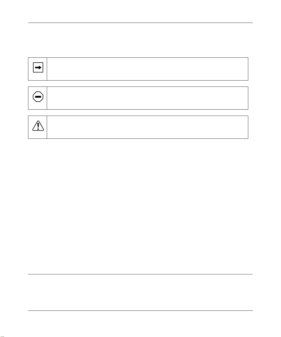
Special Message Formats
This guide uses the follo wing formats to highlight special messages.
This format is used to highlight inf ormation of importance or special interest.
Note:
Caution:
equipment failur e or loss of data.
Warning:
or equipment damage.
This format is used to highlight information that will help you preve nt
This format is used to highlight inf ormation about the possibility of inju ry
Use of Enter, Type, and Press
This guide uses “enter,” “type,” and “press” to describe the following actions:
• When you read “enter,” type the text and press the Enter key.
• When you read “type,” type the text, but do not press the Enter key.
• When you read “press,” press only the alphanumeric or named key.
• When you read “click,” click the left mouse button.
Other Conventions
This guide uses the following additional conventions:
italics
Book titles, command, and directory names.
Initial Caps Menu titles and window and button names.
Related Publication
For more information about the Model XM128U modem, refer to the
Model XM128 ISDN Digital Modem
version).
viii Preface
(Bay Networks part number M-XM128NA-1 or a later
Referenc e Guide for the
Page 9

Page 10

Page 11

Chapter 1
Introduction
This guide descr ibes how to instal l and use the Model XM128U ISDN Digital Modem. It includes
a physical description and installation instructions for the hardware, as well as instructions for
installing and using FirstGear
getting starte d. For more deta iled infor mation about installing your Model XM128U modem, refer
Reference Guide for the Model XM128 ISDN Digital Modem.
to
When used wi th o ff-the-sh elf In t ernet o r remot e acc es s client softw are, the Mo del XM128U
modem enables mobile or home use rs to connect o v er Inte gr ated Service s Digit al Networ k (ISDN)
lines to the Internet o r t o branch of fi ces. The Model XM128U m odem also a llo ws a use r to c onnect
to the analog world through an analog modem, a fax machine, or a telephone.
To take advantage of constant new developments while sustaining your hardware investment, the
Model XM128U modem uses flash EPROMs that enable convenient uploading of newly av ailable
firmware.
™
for confi guring the modem. Use this guide as a reference for
Features
The Model XM128U modem supports a variety of compress ion schemes including V.42bis and
Hi/fn LZS Compression (Stac). The Model XM128U modem can effectively communicate at
speeds up to 460 kilobits per second (Kbps) over ISDN lines.
The Model XM128U modem has two analog ports to connect analog devices such as fax
machines, modems, and telephone s. The Model XM128U modem can communicate over the two
B channels to diff erent locations simultaneousl y, enabling you to send a fax and “surf” the web at
the same time. The analog ports recogni ze standard dual-tone multifrequency (DTMF) tones as
well as pulse dialing.
Introduction 1-1
Page 12

Getting Started Using FirstGear for the Model XM128U ISDN Digital Modem
The Model XM128U modem has the following speed and compatibility features:
®
• Plug-and-Play support for a Windows
95 environmen t
• Full compatibility with both ISDN and remote public - switched telephone network (PSTN)
by way of ISDN
• Multiple signaling protocol compatibility with DSS1, 1TR6, NI-1, AT&T 5ESS, and Northern
Telecom DMS 100 network switches
• X.75, V.110, V.120, and Point-to-Point Protocol (PPP)
• B channel speeds of 56 Kbps (in-band signaling) and 64 Kbps (out-of-band signaling)
• 112 Kbps/128 Kbps channel bundling: MLP and Multipoint PPP (RFC1717)
• Hi/fn LZS compression (Stac)
• V.42bis data compression using the X.75, V.120, and bundle protocols
• Configurabilit y using either FirstGear (a Wi ndows 95 utility) or AT commands
• Automatic ISDN and analog call detection
• Two analog telephone jacks (ana log adapters)
• Push-button switch for quick dial and teardown
• Easy-to-use FirstGear configuration software
• Flash EPROM for easy firmware upgrades
1-2 Introduction
Page 13
Chapter 2
Physi cal Descr ip tion
This chapter provides information about the hardware features of the Model XM128U ISDN
Digital Modem. Use the key at the bottom of each illustration to identify the panel components.
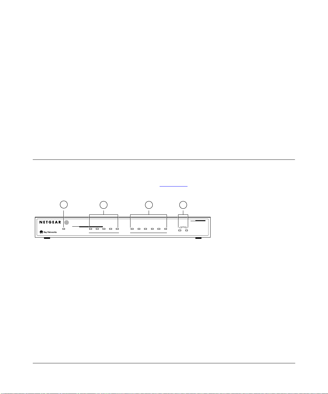
Front Panel
For easier management and control of the Model XM128U modem, familiarize yourself with the
components on the front panel, as ill ustrated in Figure 2-1.
1
INTERFACE
U
128Kpbs
ISDN Digital Modem
Key:
1 = PWR (power) LED
2 = ISDN LEDs
3 = RS-232 COM LEDs
4 = PHONE 1 and PHONE 2 LEDs
2 3 4
ISDN
DTR DSR RTS CTS TDDPWR B1 B2 AA CP
RD
COM
12
MODEL
XM128
8262EA
Figure 2-1. Front panel of the Model XM128U modem (with S/T interface)
Physical Des cription 2-1
Page 14

Getting Started Using FirstGear for the Model XM128U ISDN Digital Modem
LEDs
LEDs on the front panel of the Model XM128U modem allow you to monitor and diagnose the
device. Table 2-1 describes each LED.
Table 2-1. LED descrip t io ns
Label Color Activity Description
PWR
(Power)
ISDN LEDs:
D Green On The ISDN link on the D channel is active.
B1 Green On A connection is established to the B1 channel.
B2 Green On A connection is established to the B2 channel.
AA Green On The Model XM128U modem is in the automa tic answering mode .
CP Green On Compression is activ e on either of the B channels.
RS-232
COM LEDs:
DTR Green On The data terminal or computer connected to th e DTE port on
DSR Green On The Model XM128U modem is ready to communicate with the
RTS Green On The data terminal or computer connected to the DTE port on
CTS Green On The Model XM128U modem is ready to accept data from the
TD Green On The data terminal or computer connected to th e Mode l XM128U
RD Green On The data terminal or computer connecte d to the Model XM128U
PHONE 1 Green On The telephone connected to the port is in use.
PHONE 2 Green On The telephone connected to the port is in use.
Green On Power is supplied to the modem.
Blinking The Model XM128U modem is attempting to make a connection
to the switch.
Blinking An incoming call is ringing.
the Model XM128U modem is ready to communicate.
connected data terminal or computer.
the Model XM128U modem is ready to transmit data.
connected data terminal or computer.
modem is transmitting data to the modem.
modem is receiving dat a from the DTE port of the modem.
2-2 Physical Description
Page 15

Getting Started Using FirstGear for the Model XM128U ISDN Digital Modem
Rear Panel
As illustrated in Figure 2-2, the rear panel contains a power switch; a power receptacle; and ports
to connect a computer, ISDN line, and two analog device s (t elephone, fax, or modem).
4
1 2 3
5
ON/OFF
POWER
Key:
1 = ON/OFF switch
2 = Receptacle for power adapter
3 = RS-232 co m mun ic ation (COM) po r t for con necting to a com p ute r
4 = ISDN port for connecting to an ISDN line
5 = PHONE 1 and PHONE 2 ports for connecting analog de vices (telephone , fax, or modem)
RS-232
ISDN
PHONE 1PHONE 2
7861MEA
Figure 2-2. Rear panel of the Model XM128U modem
Table 2-2 describes the components on the rear panel of the Model XM128U modem.
Table 2-2. Rear panel components
Label Description
ON/OFF This switch turns power on or off.
POWER This receptacle is for the power adapter.
RS-232 This RS-232 COM port is for connecti ng the Model XM128U m odem to the serial port o f
a computer or data terminal.
ISDN This port is for connecting t he Model XM128U modem to the ISDN line.
PHONE 1 This port is for connecting the Model XM128U modem to an analog device (telephone,
fax, or modem) .
PHONE 2 This port is for connecting the Model XM128U modem to an analog device (telephone,
fax, or modem) .
Physical Description 2-3
Page 16

Page 17

Chapter 3
Installation
This chapter provide s information about installing and using the Model XM128U ISDN Digital
Modem.
Package Co n t e n t s
Your package should contain the following items:
• Model XM128U ISDN Digital Modem
• Power adapter
• RJ-45 ISDN telephone cable
• Shielded RS-232 25-pin straight cable
• 25-pin to 9-pin adapter
• This manual
• Reference Guide for the Model XM128 ISDN Digital Modem
• CD ROM with bundled software
• 3.5-inch driver and uti lity diskettes
• Warr a nty & Owner Registration Card
Call your reseller or customer support in your area if there are any wrong, missing, or damaged
parts. Refer to pag e ii of this manual for the location of customer support in your area.
Keep the carton , inc luding the original packing materials. Use them to repack the modem if you
need to return it for repair.
To qualify for product updates and product warranty registr ations, fill in the Warranty & Owner
Registration Card within 30 days of purchase and return it to NETGEAR, Inc.
Installation 3-1
Page 18

Getting Started Using FirstGear for the Model XM128U ISDN Digital Modem
Installing the Modem
Before connecting any of the devices to your modem, make sure the powe r is turne d off on your
computer and your Mode l XM128U modem. Then connect th e ISDN line to your mode m. Refer to
Figure 3-1 and then to the steps follo wing the illu strat ion for detaile d instr uctions f or maki ng those
connections.
1
2
4 5
3
Key:
1 = Model XM128U modem
2 = AC power adapter
3 = Computer (PC, Macintos h, or UNIX workstati on)
4 = Shielded RS-232 25-pin straight cable
5 = ISDN connection to wall outlet
6 = Analog device (telephone, fax, or modem)
Figure 3-1. Model XM128U modem connections
To install your Model XM128U modem:
6
6
7860PEA
Connect the male end of the 25-pin stra ig ht cabl e to the RS- 23 2 CO M po rt of the
1.
Model XM128U modem.
3-2 Installation
Page 19

Getting Started Using FirstGear for the Model XM128U ISDN Digital Modem
Connect the other end (female end) of the 25-pin straight cable to the serial (COM) port
2.
on your computer.
If your computer has a 9-pin serial connector, use a 25-pin to 9-pin converte r
Note:
(25-pin male to 9-pin female). If you have a Mac intosh, a special cable is needed for the
connection.
Using the special ISDN cable that is included, connect the larger end of the cable to the
3.
ISDN port on the back of the Model XM128U modem.
Connect the smaller end of the ISDN cable to the wall outlet installed by your telephone
4.
company.
Insert the round end of the power adapter in the POWER connector on the rear panel.
5.
Plug the power adapter into an AC wall outlet.
6.
Turn the power on to your Model XM128U modem.
7.
Turn the power on to your computer.
8.
Verifying Hardware Installation
When the installation is complete and power applied to the modem, a self-test sequence begins.
The B1, B2, and AA LED lights blink on and then of f aga in. Aft er this cycle is complete, the PWR
(power) LED remains on.
If the test routine fails, the D LED blinks. Refer to
Digital Modem
for more information about the self-test and the error codes.
Reference Guide for the Model XM128 ISDN
Installing Software for Windows
This section contains information about installing the Windows 95 and Windows NT® drivers and
about configuring Dial-Up Networking.
Installation 3-3
Page 20

Getting Started Using FirstGear for the Model XM128U ISDN Digital Modem
Installing the Windows 95 Driver
The Model XM128U modem is Plug-and-Play compatible with Windows 95. If you are running
Windows 95 or Windows NT , r efer to this section to install the Win dows 95 driver. If you are
running Windows 3.X, refer to Chapter 4, “Configuration,” in the
XM128 ISDN Digital Modem
for information about using a terminal program and AT commands
to configure your modem.
To install the Windows 95 driver:
Turn on power to your Model XM128U modem.
1.
Turn on power to your PC, and start Windows 95.
2.
Reference Guide for the Model
The New Hardware Fo und screen opens, as illustrated in Figure 3-2
. Windows 95 detec ts your
Model XM128U modem automatically and prompts you to indicate which driver you want to
install for your new hardware.
Figure 3-2. New Hardware Found screen
Click on the Driver from disk provided by hardware manufacturer field.
3.
3-4 Installation
Page 21

Click on OK.
4.
Getting Started Using FirstGear for the Model XM128U ISDN Digital Modem
The Install From Disk screen opens, as illustrated in Fi gure 3-3
Figure 3-3. Install From Disk screen
Insert the NETGEAR XM128 Driver Disk in the floppy drive.
5.
As instructed on the Install From Disk screen, type A:\ to find the drive r disk.
6.
Click on OK.
7.
The Select Device screen opens, as illustrated in Figure 3-4
.
.
Figure 3-4. Select Device screen
Installation 3-5
Page 22

Getting Started Using FirstGear for the Model XM128U ISDN Digital Modem
Select the desired modem driver.
8.
In most cases, depending on whether your ISP supports 64K or 128K conne ction, you will
want to select one of the following:
Netgear XM128, PPP 64K
or
Netgear XM128, MP-PPP 128K
Click on OK.
9.
Click on OK again.
10.
The installation of your XM128 modem driver is complete. You can now use programs such
as Dial-Up Networking.
Installing and Launching FirstGear
If you are not se tting up your Model XM128U modem with a comput er running Windows 95, you
must have a termina l program that allows you to send and receive AT commands and responses
from the modem. For further information about manual configuration, refer to Chapter 4,
“Configur ation,” in
Referenc e Guide for the Model XM128 ISDN Digital Modem
.
T o c onf igure your M odel XM128U mo dem with a comput er runni ng W indo ws 95, you must inst all
the NETGEAR FirstGear softwar e that is inc luded on a disk in your package contents.
3-6 Installation
Page 23

Getting Started Using FirstGear for the Model XM128U ISDN Digital Modem
To install the FirstGear software:
Insert your NETGEAR FirstGear disk into Drive A on your computer.
1.
Select Run.... from the Start menu of Windows 95.
2.
T ype A:\Setup.exe and press [Enter].
3.
The Welcome screen, as illustra ted in Figure 3-5
Figure 3-5. Welcome screen
, opens.
Follow the instructions on your screen until the installation is complete.
4.
The FirstGear softwa re installation is complete. You can now run the FirstGear softwa re.
Installation 3-7
Page 24

Getting Started Using FirstGear for the Model XM128U ISDN Digital Modem
In the final screen , check the box to launc h the applicat ion that will au tomatical ly launch
5.
the FirstGear Wizard. Figure 3-6 illustrates the Setup Complete screen.
Figure 3-6. S et up Complete screen
Firs tGear Installation Wizard
The FirstGear Installation Wizard provides step-by-step instructions to set up your ISDN Digital
Modem because installin g an ISDN modem can be somewhat c onfusing. You must enter the
telephone numbers ass igned to the ISDN line and a Service Profile ID (SPID) as well as select the
appropriate switc h type. To further complicate matters, the number of phone number s, the SPIDs,
and the actual switch type may vary based on your location within North America. In order to
simplify the installation process, your NETGEAR Model XM128U ISDN Digital Modem comes
with an Installati on Wizard. By simply entering the assigne d telephone number(s), you enable the
Wizard to a utomatically determine the corresponding SPIDs and chosen switch type.
3-8 Installation
Page 25

Getting Started Using FirstGear for the Model XM128U ISDN Digital Modem
You have a choice between launching this appl ication automatically during the insta llation of
FirstGear or running it later from the NETGEAR program group folder. Before you can run the
Wizard, you must perform the following steps:
You must first have an active ISDN line (provided by your local telephone company).
1.
You must connect the Model XM128U modem to you r PC and the ISDN l ine as de scribed
2.
on page 3-2 in “Installing the Modem.”
Make sure that power has been applied to the modem and the PWR LED is on.
3.
Install the Windows 95/NT drivers as described on page 3-4.
4.
If you opted not to launch the Wizard automatically during FirstGear installation, do so now by
double-clicki ng on the appro priate icon from the NETGEAR program group folder.
The introduction scre en opens as shown in Figure 3-7
Figure 3-7. Introduction screen
.
Installation 3-9
Page 26

Getting Started Using FirstGear for the Model XM128U ISDN Digital Modem
To launch FirstGear from the NETGEAR program folder:
Click on Next to continue, and the Telephone numbers assigned screen appears as shown
1.
in Figure 3-8.
Figure 3-8. Telephone numbers assigned screen
Refer to the information supplied by your local telephone company. If you have been
2.
assigned only one telephone number, select 1. Otherwise, select 2.
3-10 Installation
Page 27

Getting Started Using FirstGear for the Model XM128U ISDN Digital Modem
Click on Next.
3.
Based on the selection on the previous screen, you will be able to enter either one or two
telephone numbers. Enter eac h telephone number, includ ing the area code, in the Te lephone
number entry screen illustrated in Figure 3-9
.
Figure 3-9. Telephone number entry screen
Installation 3-11
Page 28

Getting Started Using FirstGear for the Model XM128U ISDN Digital Modem
After you enter the telephone number(s), click on Next to continue.
4.
At this point, the FirstGear Wizard will automatically detect the Service Profile IDs (SPIDs)
and the appropriate switch type. When the procedure is successful, the Wizard displays the
final status screen shown in Figure 3-10
.
Figure 3-10. Final status screen
Click on Finish to exit FirstGear Installation Wizard.
5.
3-12 Installation
Page 29

Getting Started Using FirstGear for the Model XM128U ISDN Digital Modem
If the Wiz ard is unable to determine the SPID and/or switch values, you will be prompted to enter
these value s directly. Refer to the information supplied by your loca l telephone company. The
ISDN Settings menu tab, as illustrated in Figure 3-11, is used to enter the SPID and switch values
directly.
Figure 3-11. ISDN Settings menu tab screen
To enter the SPID and switch va lues directly:
Enter each of the values in to the co rres ponding fields. The telep ho ne num b ers have
1.
already been entered based on values entered earlier.
Enter the corresponding SPID numbers and select the switch type from the pull-down
2.
menu.
Click on OK to continue.
3.
Based on these new values, the Wizard attempts a test call. If the call fails, you will be prompted
once again to recheck the v a lues. If the problem persists, contact NETGEAR customer support.
Installation 3-13
Page 30

Getting Started Using FirstGear for the Model XM128U ISDN Digital Modem
About FirstGear
FirstGear allo ws you to set the telephone numbers, run diagnostic s, a nd enable/disable the Call
W ai ting fe ature. When you run Fi rstGear, it automatically displays the current se tti ng of the Model
XM128U modem. Figure 3-12 shows the Configuration menu screen.
Figure 3-12. Configuration menu screen
The Telephone Numbers field displa ys the current phone number settings. Based on the
information given to you by your local telephone company, you will have either one or two
telephone numbers assigne d to your ISDN line. The appro priate radio button at the top of the
field will indicate whether you have one or two te lephone numbers assigned.
If you need to change the telephone numbers, type them into the appropriate fields (Phone #1
or Phone #2, including area codes). When saving the configuration (by clicking on OK or Apply),
FirstGear automatically detects the Service Profile IDs (SPIDs) and switch type assigned to
your ISDN line.
To enable Call Waiting on each analog phone port, check the appropriate box (Analog Port 1 and/
or Analog Port 2). To disable Call Waiting on a port, clear the box for that port.
3-14 Installation
Page 31

Getting Started Using FirstGear for the Model XM128U ISDN Digital Modem
Clicking on the buttons at the bottom of the screen will have the following results:
• OK
The OK button sav es the current configura tion and exits the program.
• Cancel
The Cancel button e xits the program without saving the current configuration.
• Apply
The Apply button sa ves the current configuration but does not exit FirstGear.
• Help
The Help button displ ays the online help.
There are also three pull-down menus: Configuration, Tools, and Help.
The Configuration menu supports four selections: Retrieve, Sav e, Auto Configure, and ISDN
Settings. Figure 3-13
shows the Configur ation menu choices.
Figure 3-13. Retrieve menu tab screen
Installation 3-15
Page 32

Getting Started Using FirstGear for the Model XM128U ISDN Digital Modem
The Configuration menu selections have the following results:
• Retrieve
Selecting Retrieve allows you to re view the current setting of the Model XM128U modem.
• Save
Selecting Sa ve allows you to update the modem with the new settings.
• Auto Configure
Selecting Aut o Confi gur e causes the m odem t o automat ical ly detec t the SPIDs a nd switc h type
based on the current telephone number s.
• ISDN Settings
Selecting ISDN Settings displays the current ISDN settings including the telephone numbers,
SPIDs, and switch type.
Figure 3-14
Figure 3-14. ISDN Settings menu tab screen
shows the ISDN Settings menu bar.
3-16 Installation
Page 33

Getting Started Using FirstGear for the Model XM128U ISDN Digital Modem
The Tools menu provides you with the ability to program some of the advanced features usi ng
AT commands as well as a diagnostic tool.
Figure 3-15
Figure 3-15. T ools menu screen
shows the Tools menu choices displayed.
By selecting the AT Commands menu bar, you can enter AT commands directly to set some of
the advanced features of the Model XM128U modem (refer to the
Reference Guide for the Model
XM128 ISDN Digital Modem).
The Diagnostics Menu prov ides the following two select ions:
• Self Test
Self Test checks the Model XM128U modem hardware inte grity.
• Test Call
T est Call checks the inte grity of the ISDN connection by plac ing a call f rom the fir st telephone
number to the second telephone number. Be aware that you may be charged for this call by
your local telephone company.
Installation 3-17
Page 34

Getting Started Using FirstGear for the Model XM128U ISDN Digital Modem
The Help menu allows you to retrieve an online version of this manual. Figure 3-16 shows the
Help menu bar selected.
Figure 3-16. Help menu screen
Configuring Windows 95 Dial-Up Ne tworking
You must install Windows 95 and Dial-Up Networking before proceeding with this section.
Configuring Dial-Up Networking for One B Channel
To configure your Model XM128U modem with Dial-Up Networking for one B channel:
Double-click on the My Computer icon.
1.
Double-click on the Dial-Up Networking folder.
2.
3-18 Installation
Page 35

Getting Started Using FirstGear for the Model XM128U ISDN Digital Modem
Double-click on the Make New Connection icon from within the Dial-Up Networking
3.
folder.
The Make New Connection screen, as illustrated in Figure 3-17
Figure 3-17. Make New Connection screen
Type a name for your connection in the Type a name for the computer you are dialing
4.
, open s.
field.
Select the appropriate Model XM128U modem driver for the dial-up connection.
5.
Each dial-up connection c an use a different Model XM128U modem driver. Each driver
automatically sel ects the appropriate protocol and data rate. For example, you may want
to use the Netgear XM128, Internet PPP 64K driver for your 64K connec tion to your remote
LAN while you are telecommuting. On the other hand, you can set up a second dial-up
connection with the Netgear XM128, Internet PPP 128K driver for your 128K Internet
connection through your local ISP. Each dial-up connection uses a different driver.
Installation 3-19
Page 36

Getting Started Using FirstGear for the Model XM128U ISDN Digital Modem
Click on Next.
6.
The second Make New Connect ion screen opens, as illust rat ed in Figure 3-18
Figure 3-18. Make New Connection screen for entering ISP information
T ype the phone number of the Internet service provider (ISP) or host you will be calling.
7.
Click on Next.
8.
.
Click on Finish.
9.
A new icon is created in the Dial-Up Networking folder.
If your ISP requires you to enter DNS and WINS addresses, perform steps 10 through 18.
Otherwise, proceed to step 19.
3-20 Installation
Page 37

Getting Started Using FirstGear for the Model XM128U ISDN Digital Modem
Select the new icon in the Dial-Up Networking folder, and click on the right mouse
10.
button.
Select Properti es from th e me nu .
11.
The My Connection screen, as illustrated in Figure 3-19
Figure 3-19. My Connection screen
, opens.
Make sure that y our Model XM128U modem appears in the Connect usin g box.
12.
If you have settings given to you by your ISP, follow those guidelines and go to step 20 on
page 3-23
If you do
Installation 3-21
.
not
have guidelines given to you by your ISP, go to step 13.
Page 38

Getting Started Using FirstGear for the Model XM128U ISDN Digital Modem
Click on the Server Types tab.
13.
The Server Types tab opens, as illustrated in Figure 3-20
If you are using PPP, use the de fault settings shown in Figure 3-20
.
.
If you are connecting to a LAN, select Log on to network.
®
If you are logging on to a Microsoft
Windo ws network, select NetBEUI.
If you are logging on to a Novell network, select IPX/SPX Compatible.
If you are logging on to an Internet connection, select TCP/IP.
Figure 3-20. Server Types tab screen
3-22 Installation
Page 39

Click on TCP/IP Settings.
14.
Getting Started Using FirstGear for the Model XM128U ISDN Digital Modem
The TCP/IP Settings screen, as illustrated in Figure 3-21
Figure 3-21. TCP/IP Settings screen
Click on the Specify name server addresses radio button.
15.
, opens.
Enter your primary and secondary Domain Name Server (DNS ) numbers.
16.
Obtain DNS numbers from your ISP. If your host requires you to specify an IP address,
go to the next step. If your host does not require you to specify an IP address, go to step 18.
Click on Specify an IP address and enter your IP address only.
17.
Click on OK
18.
.
This step completes the remote connection definition.
Locate the icon of the connection profile you created in your Dial-Up Networking folder
19.
and double-click on it.
Type the user name and password for your ISP if they are incorrect or missing .
20.
Click on the Connect button.
21.
Your Model XM128U modem dials the number and establishes a connection.
This step completes the configuration of Dial-Up Networking f or Windows 95.
Installation 3-23
Page 40

Getting Started Using FirstGear for the Model XM128U ISDN Digital Modem
Configuring Dial-Up Networking for Two B Channels
To configure your Model XM128U modem for use with two B channels using Multilink PPP:
Double-click on the My Computer icon.
1.
Double-click on the Dial-Up Networking folder.
2.
Double-click on the Make New Connection icon from within the Dial-Up Networking
3.
folder.
Choose a name for your connection and select XM128 from the drop-down menu.
4.
Select Netgear XM128, Internet PPP 128K.
5.
Click on Next.
6.
The Make New Connection screen, as illustrated in Figure 3-18
Type the phone number(s) of the ISP or host you will be calling .
7.
on page 3-20, opens.
Some ISPs require only one phone number to make multiple-link connection. If your ISP
requires you to dial a different number (one for each B channel), separate the two numbers
with a plus sign ( +). Ot herwise, enter t he number as n ormal ( for e xample: 5551 111+55522 22).
Click on Next.
8.
Click on Finish.
9.
A new icon is created in the Dial-Up Networking folder.
Click your right mouse button on the new icon.
10.
Select Properti es from th e pop-up menu.
11.
The My Connection screen, as illustrated in Figure 3-19
on page 3-21, opens.
Make sure the Use country code and area code field is not chec ked off. If this field is c hecked,
Windows 95 removes the plus sign (+) from the phone number when you close the window,
which causes failed co nnections in the future.
Make sure your Netgear XM128, Interne t PPP 128K appears in the Connect using box. If
settings ha ve been given to you by your ISP, follow those guidelines and go to step 20 on
page 3-23
If settings have
.
not
been given to you by your ISP, go to step 13 on page 3-22
.
Either choice completes the configuration of Dial-Up Networking for Windows 95 using two
B channels.
3-24 Installation
Page 41

B
bulleti n b oa rd service ii
C
Configuration menu screen 3-14
conventions
customer support
vii
ii
F
features 1-1
FirstGe a r so ftware, ins ta lling
front pa nel
2-1
3-6
M
Make New Connection screen 3-19, 3-20
My Connecti on screen
3-21
N
New Hardware Found screen 3-4
NT driver, installing
3-3
O
ON/OFF switch 2-3
Index
H
Help menu screen 3-18
I
Install From Disk screen 3-4, 3-5
3-2
2-3
3-9
installation
Introduction screen
ISDN port
ISDN Settings menu tab screen
3-13
package contents 3-1
2-3
2-3
2-3
PHONE 1 port
PHONE 2 port
2-3
ports
power receptacle
R
rear pan el 2-3
relate d publicato n
Retrieve menu tab screen
x
3-15
L
Launch screen 3-8
P
LED descriptions
Index 1
2-2, 3-3
Page 42

S
screens
3-18
3-9
3-17
3-5
3-16
3-21
3-14
3-4, 3-5
3-15
3-22
3-23
3-5
3-22
Configuration menu
Finish In s ta lla tion Wizard
2-3
2-3
3-8
3-7
Help Menu
Install From Disk
Introduction
ISDN menu tab
ISDN Settings menu tab
ISDN Settings menu tab screen
Launch
Make New Connection
My Connecti on
New Hardware Found
Retrieve menu tab
Select Devi ce
Server Types tab
TCP/ IP Settings
Telephone number entry
Telephone numbers assigned
Tools menu
Welcome
Select Device screen
serial port
Serve r Types tab scree n
switch
3-12
3-13
3-19, 3-20
3-4
3-11
3-10
3-16
T
TCP/ IP Settings scree n 3-23
Telephone number entry screen
Telephone numbers assigned screen
Tools menu sc reen
3-17
3-11
3-10
U
Use viii
W
Welcome screen 3-7
Windows 95
configu ring Di al-Up Net working f or one B cha nnel
3-18
configuring Dial-U p N etworking fo r two B
channels
dri ver, installing
Wo rld Wide Web
3-24
3-4
ii
2 Index
 Loading...