

Page 1

Reference Guide for the Model XM128 ISDN Digital Modem
NETGEAR, Inc.
A Bay Networks Company
48105 Warm Springs Blvd.
Fremont, CA 94539
USA
M-XM128NA-1
November 1997
Page 2

© 1997 by NETGEAR, Inc. All rights reserved.
T rademarks
Bay Networks is a registered trademark of Bay Networ ks, Inc.
NETGEAR and Fir stGear are tr ademarks Bay Networks, Inc .
Microsoft, Windows, and Windows NT are registered trademarks of Microsoft Corporation.
Other bra nd and product names are tradem arks of their respective holders.
Statement of Conditions
In the interest of improving internal design, operational function, and/o r reliability, NETGEAR reserves the right to
make changes to the products described in this document without notice.
NETGEAR does not assume an y liability that may occur due to the use or application of the product(s) or circuit
layout(s) described herein.
Federal Communications Commission (FCC) Compliance Notice: Radio Frequency Notice
This de vice complies wi th part 15 of the FCC Rules. Operation is subject to the follo w ing two condit ions:
• This de vice may not cause harmful interference.
• This device must ac cept any inte rference re ceived, including interference that may cause undesired operation.
Note: Thi s equipment has be en tested and fo und to comply with the limits for a Class B digital device, pur suant to part
15 of the FCC R u les. These lim its are designed to provide reasonable protecti on against harmful interference in a
residential installation. This equipment generates, uses, and can radiate radio frequency energy and, if not installed and
used in accordance with the instructions, may cause harmful interference to radio communications. However, there is n o
guarant ee tha t in te rf erenc e wil l no t oc cur in a pa rt ic ular ins ta llat io n. I f this equi pme nt do es ca use har mful in te rf erenc e to
radio or tele vision rec eption, which can be de termined by turning the equipm ent off and on, th e user is encouraged to try
to correct the interference by one or mo re of the following measures:
• Reorient or relocate the receiving antenna.
• Increase the separation between the equipment and receiver.
• Connect t he equipment int o an outlet on a circuit different from that to which the receiver is connected.
• Consult the dealer or an experienced radio/TV technician for help.
EN 55 022 Declaration of Conformance
This is to certify that the NETGEAR Model XM128 Digital Modem is sh ielded agai nst the genera tion of radio
inter ference in accordance with the application of Council Di rective 89/336/EEC, Article 4a. C onformity is declared by
the application of EN 55 022 Class B (CISPR 22).
ii
Page 3

Bestätigung des Herstellers/Importeurs
Es wird hiermit bestätigt, daß das Model NETGEAR Model XM 128 ISDN Digital Modem gemäß der im
BMPT-Amtsbl Vfg 24 3/1991 und Vfg 46/ 199 2 aufg ef ühr ten Be st immung en ent stör t i st. Das v or schri f tsmä ßige Bet reibe n
einiger G eräte (z.B. Test sender) kann jedoch gewissen Beschränkungen unterliegen. Lese n Sie dazu bitte die
Anmerk ungen in der Betriebsanleitung.
Das Bundesamt für Zulassungen in der Telekommunikation wu rde davon unt errichtet, daß dieses Gerät auf den Markt
gebrach t w urde und es ist berechtigt, die Serie auf die Erfüllung der Vorschriften hin zu überprüfen.
Certificate of the Manufacturer/Importer
It is hereby certified that the N ETG EA R M odel XM128 Digital Modem has been suppressed in accordance with the
conditions set out in the BMPT-AmtsblVfg 243/1991 and Vfg 46/199 2. The operation of some equi pment (for example,
test transmitters) in accordance with the regulations may, however, be subject to certain restrictions. Please refer to the
notes in the operating instructions.
Federal Office for Telecommunications Approvals has been notified of the placing of this equipment on the market and
has been granted th e right to te st the series for com p li ance wit h th e regulations.
VCCI-2 Statement
This equi pment is in the second Class category (informatio n equipment to be used in a reside ntial area o r an adjacent
area the reto) and conforms to the standards set by th e Voluntary Control Council for Interference by Data Processing
Equipment and Electronic Office Machines aimed at preventing radio interference in such residential areas.
When used near a radio or TV rec eiver, it may become the cause of radio interference.
Read instructions for correct handling.
Customer Support
For ass istance with installing and configuri ng your NETGEAR system or w ith post-installation questions or problems,
contact your point of purchase representative.
To contact customer suppo rt or to purchase additional copies of this document and publ ications for other NETGEAR
products, you can contact NETGEAR at the following numbers:
• Phone:
U.S./Cana da:1-800-211-2069
Japan: 0120-66-5402
Europe: (4 4) 171-571-512 0
Australi a:1-800-142-046
•Fax:
U.S./Canada: 510-498-2609
iii
Page 4

World Wide Web
NETGEAR maintains a World Wide Web Home Page that you can access at the universal resource locator (URL)
http://NETGEAR.baynetworks.com. A direct connection to the Internet and a Web browser such as Internet Explorer
or Netscape ar e required.
Bulletin Board Service
NETGEAR maintains a b ulletin board that you can access to obtain inform ation about the latest version of the software.
In the United States, ph one 407-531-457 4.
iv
Page 5

Reference Guide for the Model XM128 ISDN Digital Modem
Contents
Preface
Purpose ..........................................................................................................................xvii
Conventions ...................................................................................................................xviii
Special Message Formats .......................................................................................xviii
Use of Enter, Type, and Press .................................................................................xviii
Other Conventions ............. ......... .......... ......... .......... ......... .......... ......... .......... ......... ..xix
Related Publication ..........................................................................................................xix
Chapter 1
Introduction
Features ..........................................................................................................................1-1
Interface Options ........... .......... ......... ......... .......... ......... .......... ......... .......... ......... ......1-3
Front Panel .....................................................................................................................1-3
Rear Panel ......................................................................................................................1-6
Chapter 2
Installation
Package Contents ..........................................................................................................2-1
Installing the Modem ......................................................................................................2-2
Verifying Hardware Installation .......................................................................................2-3
Chapter 3
Setup for Windows 95 and Windows NT 4.0
Selecting the Appropriate Windows 95 Driver (INF file) ................................................. 3-1
Contents v
Page 6

Reference Guide for the Model XM128 ISDN Digital Modem
Chapter 4
Configuration
Configuring Your ISDN Line and Network ......................................................................4-1
Configuring Your Modem Using a Terminal Program .....................................................4-1
Understanding AT Commands ................................... .. .......... ....... ....... .. .......... ....... .4-2
Quick Tips for Issuing AT Commands ................................................................4-3
Using AT Commands to Verify Modem Response .............................................4-4
Communication Speed Setup ................. ....... ....... ....... ..... ....... ....... ..... ....... ....... ......4-4
Switch Type Setup for North America ................................................................4-5
SPID Setup for North America ...........................................................................4-6
Entering DNs ............................................................................................................ 4-7
Setup for Europe and the United Kingdom .................................... ....... ....... ......4-7
Chapter 5
Async to Sync PPP
Internet and Remote Access PPP and SLIP .................................................................. 5-1
Making Async to Sync PPP and SLIP calls .............................................................. 5-1
Keeping a Line Connection During Idle Time ................................ ....... ....... ..... .5-2
Answering Async to Sync PPP calls ...............................................................................5-3
Multilink PPP ............................................................................................................5-3
Making a call using Mu ltilink PPP .......................... .......... ......... .......... ......... ......5-3
Dialing Pre-stored Phone Numbers .........................................................................5-4
Endpoint Discriminator . .....................................................................................5-4
Call Bumping Dynamic Channel Allocation . .............................................................5-5
Chapter 6
ISDN Overview
Commands for Outgoing Calls ........................................................................................6-1
Dialing Out Using ISDN Mode ..................................................................................6-1
Dialing Out Using ISDN Mode Optional Speech Bearer Service .............................6-2
Dialing Out for Analog Adapter Port 1 ......................................................................6-2
Dialing Out for Analog Adapter Port 2 ......................................................................6-2
Manually Switching Communication Modes ............................................................. 6-2
Placing the Call ........................................................................................................6-3
vi Contents
Page 7

Reference Guide for the Model XM128 ISDN Digital Modem
Commands for Incoming Calls ........................................................................................6-4
Digital Data ............................................................................................................... 6-4
Determining the Packet Length ................................................................................6-5
Answering a Call Using MSN ...................................................................................6-6
Data over Speech Channel ................................................ ....... ....... ..... ....... ......6-7
Best-effort Call Answering ................................................................................. 6-7
Ambiguity Resolution Switch for Voice Calls .....................................................6-8
Multi Auto-Answering of Data Calls ...................................................................6-8
Understanding ISDN Communication Protocols ....................................................... ..... .6-9
V.110 ISDN Commun ications .................................................................................6-10
Answering a V.110 Call .................................................................................... 6-10
Making a V.110 Call .........................................................................................6 -10
V.120 ISDN Commun ications .................................................................................6-11
Selecting V.120 for European ISDN (DSS1) Switch ........................................ 6 -11
Selecting V.120 for German Nat ional ISDN (1TR6) .........................................6-11
Answering a V.120 Call .................................................................................... 6-12
Making a V.120 Call .........................................................................................6 -12
Configuring the V.120 Mode . .....................................................................6-12
Dialing in V.120 Mode ...............................................................................6-13
Making a Bundled Call with V.120 .............................................................6-13
Identifying Your Line Provisioning .............................................................6-14
128 Kbps Speeds ......................................................................................6 -15
Dialing Prestored Phone Numbers ............................................................6-15
Error Correction and Data Compression with V.120 .................................6-15
X.75 ISDN Communications (Europe) ...................................................................6-16
Answering an X.75 Call ...................................................................................6-16
Making an X.75 Call ........................................................................................6 -17
Making a Bundled Call with X.75 ..............................................................6-17
Dialing Prestored Phone Numbers ............................................................6-18
Invoking V.42bis Data Compression ..........................................................6-18
Bundle Connection with V.42bi s Data Compression .................................6-19
Contents vii
Page 8

Reference Guide for the Model XM128 ISDN Digital Modem
Chapter 7
Advanced ISDN
Call Control for DSS1 .....................................................................................................7-1
Control of Outgoing Service Indicator ......................................................................7-2
Control of ISDN Phone Numbers and Subaddresses ..............................................7-3
Call Control for 1TR6 (Old German ISDN) .....................................................................7-5
Control of Outgoing Service Indicator ......................................................................7-5
Control of EAZ (ENDGERÄTEAUSWAHLZIFFER) ..................................................7-6
Command Functio n .............. .......... ......... .......... ......... .......... ......... .......... ......... .7-6
Answering a Call .............................................................................................................7-7
Answering a Call for DSS1 ....................................................................................... 7-7
Answering a Call for 1TR6 .......................................................................................7-8
Best-effort Call Answering ........................................................................................7-8
Ambiguity Resolution Switch for Voice Calls ............................................................ 7-9
Multi-Auto-Answering of Data Calls ..........................................................................7-9
Data Call Indication .........................................................................................7-10
Disable Inbound Call Connection ........................................... .. ....... .......... .. ....7-10
Point-to-Point Configuration .............................................................................7-11
Placing a Call ................................................................................................................7-11
Placing a Call for DSS1 ..........................................................................................7-11
Placing a Call for 1TR6 ..........................................................................................7-12
User-To-User Information .......................................................................................7-13
Chapter 8
Analog Call Handling
AT Commands for Analog Calls ......................................................................................8-2
Making and Receiving Analog Calls ...............................................................................8-3
Placing a Call from the Analog Adapter ...................................................................8-3
Accepting an Incoming Call ......................................................................................8-4
Chapter 9
Modem Upgrade
Upgrading with Flash EPROM ........................................................................................ 9-1
Upgrad e Instructions ............ .......... ......... .......... ......... .......... ......... ......... .......... ........9-2
Kernel Mode . ............................................................................................................9-2
viii Contents
Page 9

Reference Guide for the Model XM128 ISDN Digital Modem
Chapter 10
Troublesho oting
P o we r -o n Se lf-test ............... .......... ......... ......... .......... ......... .......... ......... .......... ......... ....10-1
Loopback Tests ............................................................................................. ................10-2
ISDN Loopback test (AT&T9) .................................................................................10-2
Loopback with Self-test (AT&T10) . .........................................................................10-2
B1/B2 Loopback with Self-test ...............................................................................10-3
The Diagnostic Command ................. ....... ..... ....... ....... ..... ....... ....... ....... ..... ....... ....... ....10-3
Modem Reset .................. .......... ......... .......... ......... .......... ......... .......... ......... .......... .10-4
Using The Embedded Protocol Analyzer ........................................ ....... ..... ....... ....10-4
Setting up the Embedded EPA ........................................................................1 0-5
Capturing the Protocol Data ............................................................................1 0-5
Analyzing the Captured Data ...........................................................................10-6
...............................................................................................................................10-8
Appendix A
Technical Specifications
General Specifications ...................................................................................................A-1
Appendix B
Security Functions
Security Types and Levels . ......... .......... ......... .......... ......... .......... .................. .......... .......B-1
Level 1 Security .......................................................................................................B-2
Level 2 Security .......................................................................................................B-2
Level 3 Security .......................................................................................................B-3
Setting and Modifying Passwords ..................................................................................B-3
Nonpassword Auto Callback Function ........... ....... ....... ....... ..... ....... ....... ....... .......... .......B-4
Appendix C
AT Command Set Reference
Operation Mode of the DTE Interface ............................................................................C-1
Simplex Mode .................................. ....... ....... ....... ..... ....... ....... ..... ....... ....... ....... .....C-1
AT Command Descriptions ............................................................................................C-2
Description of ATI3 Output ......................................................................................C-7
Contents ix
Page 10

Reference Guide for the Model XM128 ISDN Digital Modem
Appendix D
Status Registers and Result Codes
Viewing and Setting S-Registers ...................................................................................D-1
Setting S-Registers .................................................................................................D-2
Examples for Setting S-Reg isters ................. ......... .......... ......... .......... ......... .....D-2
S-Register Descriptions ..........................................................................................D-4
ATXn Result Code Option Table ............................................................................D-19
Result Code Chart Symbol Reference ..................................................................D-21
Result Code Field Descrip ti o n s ............... ................... .......... .................. ...............D-22
Connect Strings for Error Corrected Connections ............................................ .....D-23
Appendix E
Connector Pin Assignments
RJ-45 Plug and Connector ...................................................... ....... ..... ....... ....... ....... .....E-1
RJ-11 Plug and Connector ...................................................... ....... ..... ....... ....... ....... .....E-3
Appendix F
Serial Port Interface
RS-232 Serial Interface ..................................................................................................F-1
Asynchronous Cable Connections ................................... .. .......... ....... .. ....... .......... ....... .F-2
Appendix G
ISDN Reference
ISDN Overview ..............................................................................................................G-1
Basic Rate Interface ................................................................................................G-2
Out-of- Ba n d Sig nal ing ............... ......... .......... ......... .......... ......... .......... ......... .......... ..G-2
Terminal Adapter or Digital Modem .........................................................................G-3
ISDN Basic Rate Interface Points ........................................................................... G -3
SPID Setup .............................................................................................................G-4
Ordering ISDN Service ..................................................................................................G -4
Order Fo rm fo r AT&T 5ESS Switch (NI-1 ISD N) ............. ......... .......... ......... .......... .........G-6
Order Form for DMS-100 Switch (NI-1 or Custom ISDN) ..............................................G -7
Order Form for EWSD (NI-1 ISDN) ............................................................................... G -8
Index
x Contents
Page 11

Figures
Figure 1-1. Front panel of the Model XM128 modem (with S/T interface) ..................1-3
Figure 1-2. Front panel of the Model XM128 modem (with U interface) .....................1-4
Figure 1-3. Rear panel of the Model XM128 modem (with S interface) .....................1-6
Figure 1-4. Rear panel of the Model XM128 modem (with U interface) .....................1-6
Figure 2-1. Model XM128 modem connections .................................................. ....... .2-2
Figure E-1. RJ-45 plug and RJ-45 connector ............................................................E-1
Figure E-2. RJ-11 plug and RJ-11 connector ............................................................E-3
Figures xi
Page 12

xii Figures
Page 13

Tables
Table 1. Manual contents ........................................................................................xix
Table 2. Manuals ...................................................................................................xx
Table 1-1. Interface options ......................................................................................1-3
Table 1-2. LED descriptions ......................................................................................1-4
Table 1-3. Rear panel components .................................................. ....... .......... .. ......1-7
Table 4-1. Terminal programs ...................................................................................4-2
Table 4-2. Suppor ted AT command types .................................................................4-3
Table 4-3. Result codes commands ..........................................................................4-4
Table 4-4. Switches supported by the Model XM128 modem ..................................4-5
Table 4-5. AT commands for setting protocols ..........................................................4-8
Table 4-6. AT commands for setting MSN ................................................................4-8
Table 5-1. S85 register values ..................................................................................5-4
Table 6-1. Dialing commands ...................................................................................6-3
Table 6-2. Call placing commands ............................................................................6-3
Table 6-3. Commands for assigning ISDN numbers .................................................6-6
Table 6-4. Best-effort call answering bit commands .................................................6-8
Table 6-5. ISDN protocol specifications ....................................................................6-9
Table 6-6. V.110 configuration commands .............................................................. 6 -10
Tables xiii
Page 14

Table 7-1. S-register values and functi o n s ............. .......... ......... .......... ......... .......... ...7-2
Table 7-2. Outgoing low-layer compatibility commands ............................................7-3
Table 8-1. Frequently used AT commands ................................................................8-2
Table 8-2. Frequently used AT commands (Europ ean switches) .............................. 8-2
Table 9-1. Definitions for the d modifier .................................................................... 9-1
Table 10-1. Power-on self-test ..................................................................................10-1
Table 10-2. EPA Commands ................................................ ....... ..... ....... .. .......... ......10-6
Table 10-3. Comm ands for analyzing captured data ................................................10-6
Table 10-4. Control key functions .............................................................................10-7
Table B-1. Types of security .....................................................................................B-2
Table B-2. Levels of security ....................................................................................B-3
Table B-3. Auto callback commands ........................................................................ B-4
Table C-1. Basic AT command set ...........................................................................C-2
Table C-2. ATI3 command output .............................................................................C-8
Table C-3. Extended AT& command set ...................................................................C-8
Table C-4. Extended AT* command set .................................................................. C-12
Table D-1. Bi n ary con version tab le ...... .......... ......... .......... ......... .......... ......... .......... ..D-3
Table D-2. Setting bit 3 .............................................................................................D-3
Table D-3. Basic S-registers ATSn=x .......................................................................D-4
Table D-4. Extended S-registers ATSn=x .................................................................D-5
Table D-5. ATXn command setting options ............................................................D-19
Table D-6. Result code char t ..................................................................................D-21
Table D-7. Result code field descrip tio ns ...............................................................D-22
Table D-8. Connect strings .....................................................................................D-23
xiv Tables
Page 15

Table E-1. RJ-45 plug and RJ-45 connector pin assignments for the S/T interface . E-2
Table E-2. RJ-45 plug and RJ-45 connector pin assignments for the U interface .... E-2
Table E-3. RJ-11 connector pin assignments ........................................................... E-3
Table F-1. Serial port interface ..................................................................................F-1
Table F-2. Asynchronous flow control cable connection ...........................................F-2
Table G-1. ISDN line configuration ...........................................................................G-6
Table G-2. ISDN line configuration ...........................................................................G-7
Table G-3. ISDN line configuration ...........................................................................G-8
Tables xv
Page 16

xvi Tables
Page 17

Preface
Congratulation s on your purch ase of the NETGEAR™ Model XM128 ISDN Digital Modem.
The NETGEAR Model XM128 modem provides connection for one or more PCs to the Internet
or to the office over ISDN (Integrated Services Digital Network) lines. The modem operates
at a speed of up to 460 kilobits per second (Kbps) data rate, or 115 Kbps data rate without
compression, and can download video clips, music, or high-resolution color graphics from the
World Wide Web or other online services many times faster than an analog modem. The Model
XM128 modem supports concurrent data and voice communications, reducing cost and
administrati on of multiple phone lines.
Purpose
This guide provides instructions for the installat ion and use of the Model XM128 modem. This
guide also prov ides inst ru ctions for the inst alla tion and us e of Fir stGear™, a configuration software
application for insta lling, configuring, and monitoring the Model XM128 modem.
Preface xvii
Page 18
Reference Guide for the Model XM128 ISDN Digital Modem
Conventions
This section describes the conventions used in this guide.
Special Message Formats
This guide uses the follo wing formats to highlight special messages.
This format is used to highlight inf ormation of importance or special interest.
Note:
Caution:
equipment failur e or loss of data.
Warning:
equipment damage.
This format is used to highlight information that will help you preve nt
This format is used to highlight mate rial inv olving possibility of injury or
Use of Enter, Type, and Press
This guide uses “enter,” “type,” and “press” to describe the following actions:
• When you read “enter,” type the text and press the Enter key.
• When you read “type,” type the text, but do not press the Enter key.
• When you read “press,” press only the alphanumeric or named key.
• When you read “click,” click the left mouse button.
xviii Preface
Page 19

Reference Guide for the Model XM128 ISDN Digital Modem
Other Conventions
This guide uses the following additional conventions:
italics
courie r fon t
Book titles and UNIX file, command, and directory names.
Screen text, user-typed command-line entries.
Initial Caps Menu titles and window and button names.
[Enter] Named keys in text are sh own enclosed in square brackets. The notation
[Enter] is used for the Enter key and the Return key.
[Ctrl]+C Two or more keys that must be pressed simultaneously are shown in text
linked with a plus (+) sign.
ALL CAPS DOS file and directo ry names.
Related Publication
Refer to
installati on guide. Refer to Table 1 to identify the contents of bot h manuals. The subje ct column in
this table identifies the order of basic proc ed ures you must complete to install your Model XM128
modem.
T able 1. Manual contents
Getting Started Using FirstGear for the Model XM128 ISDN Digital Modem
for a quick
Getting Started Using FirstGear
Subject
Installing modem hardware Chapter 3 Chapter 2
Configuring the modem Chapter 3
Installing th e W indows 95 and
Windows NT Driver
Installing Fir stGear Chapter 3 No information given.
Assigning ISDN numbers Chapter 3 Chapter 4 and Chapter 5
for the Model XM128 ISDN Digital
Modem
(If you are using Windows
or Windows NT
Chapter 3 No information given.
®
)
®
95
Reference Guide for the Model
XM128 ISDN Digital Modem
Chapter 4
(If you are using a terminal
program.)
(For using AT commands when
assigning ISDN numbers.)
Preface xix
Page 20

Reference Guide for the Model XM128 ISDN Digital Modem
Table 1. Manual conten t s (c ont i nued)
Getting Started Using FirstGear
Subject
Assigning multiple subscriber
numbers
Assigning proto cols Chapter 3 Chapter 4 and Chapter 5
Configuring Windows 95 Dial -Up
Networking
for the Model XM128 ISDN Digital
Modem
Chapter 3 Chapter 5
Chapter 3 See:
Reference Guide for the Model
XM128 ISDN Digital Modem
(For using AT commands when
assigning multiple subscriber
numbers.)
(For using AT commands when
assigning proto cols.)
Getting Started Using
FirstGear
Table 2 lists the manuals that are available for various localized products.
T able 2. Manuals
Language
English Model XM128S
English Model XM128AU
Japanese Model XM128D
German Model XM128GE
Korean M odel XM128KO
Product Model/
Version
International
North America
Japanese
German
Korean
Interface
S/T M-XM128NA-0 M1-XM128S-0
U M-XM128NA-0 M1-XM128U-0
DSU M-XM128JP-0 M1-XM128JP-0
S/T M-XM128NA-0 M1-XM128S-0
U M-XM128KO-0 M1-XM128KO-0
Reference
Manual
FirstGear
Manual
xx Preface
Page 21

Chapter 1
Introduction
Congratulation s on your purch ase of the NETGEAR Model XM128 ISDN Digital Modem. The
Model XM128 modem sets a new price and performance standard for the rapid ly growing Inter net
and telecommuting applic ations.
When used with off-the -shelf Inte rnet or remote access client software, the Model XM128 modem
enables mobile or home users to easil y connec t to the Internet or branch offices over Integr ated
Services Digital Network ( ISDN) lines. The same device also allo ws a user to connect to the
analog world via a modem, fax machine, or telephone connected directly to the Model XM128
modem.
To take advantage of constant new dev elopments, the Model XM128 modem employs flash
EPROMs, which allow for conv enient uploading of newly available fi rmware that preserves your
hardware investment.
The Model XM128 modem supports both D and B channel protocols. For the D channel,
it supports DSS1, 1TR 6, DMS-100, AT&T Custom, and NI-1. For the B channel, it supports
X.75 SLIP, V.120, V.110, PPP Async-to-sync Conversion and Bundle (128 Kbps).
With its Hi/fn LZS or V.42bis compression on the B channel using eit her X. 75 or V.120, the Model
XM128 modem can effectively communicate at speeds up to 460 kilobits per second (Kbps) over
ISDN lines.
Features
The Model XM128 modem supports a variet y of compres sion schemes including V.42bis and
Hi/fn LZS Compression (STAC) and communicates effectively at speeds up to 460 kilobits per
second (Kbps) ov er ISDN line s.
Introduction 1-1
Page 22

Reference Guide for the Model XM128 ISDN Digital Modem
The Model XM128 modem has two analog ports to connect analog devices such as fax machines,
modems, and telephones. Two different devic es can communicate over the two B channels to
different locations simultaneously, enabling you to send a fax and make a voice call at the same
time. The analog ports recognize standard dual-tone multifrequency (DTMF) tones as well as
pulse dialing.
The Model XM128 modem has the following featur es:
• Plug-and-Play support for a windows 95
®
environment
• Full compatibility with both ISDN and remote public-switched telephone network (PSTN) by
way of ISDN
• Multiple signaling protocol compatibility with DSS1, 1TR6, NI -1, AT&T 5ESS, and Northern
Telecom DMS 100 network switches
• X.75, V.110, V.120, and Point-to-Point Protocol (PPP) Async-to-Sync Conversion B Channel
Protocol support
• B channel speeds of 56 Kbps (in-band signaling) and 64 Kbps (out-of-band signaling)
• MLP and Multipoint PPP (RFC1717)
• Hi/fn LZS compression (STAC)
• V.42bis data compression using the X.75, V.120, and bundle protocols
• NETGEAR ISDN A T modem commands
• Automatic ISDN and analog call detection
• Two a nal og telephone jacks (analog adapters)
• Push-button switch for quick dial and teardown
• Easy-to-use configuration software
• Flas h EPROM me mo ry fo r easy firmware upg rad e s
1-2 Introduction
Page 23
Reference Guide for the Model XM128 ISDN Digital Modem
Interface Options
Several interfaces are available. Table 1-1 lists the interface options for the Model XM128 modem
as applicable for each region.
Table 1-1. Interface options
XM128NA XM128GE XM128UK XM128AU XM128JP
Unit XM128U XM128S XM128S XM128S XM128D
Region North America Germany UK Australia Japan
Interface U (internal NT -1) S/T S/T S/T Internal DSU
Auto SPID Switch
For the North American I SDN, NETGEAR provides an optional 2B1Q U interface to allow direct
connection to the networ k without the use of an external NT-1 devi ce.
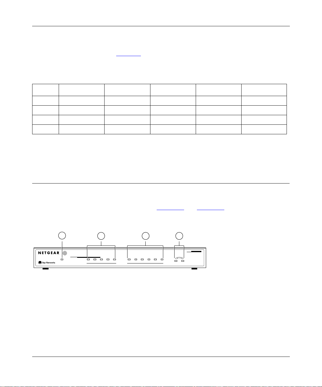
Front Panel
For easier management and control of the Model XM128 modem, familiarize yourself with the
components on the front panel, as ill ustrated in Figure 1-1 and Figure 1-2. Use the key at the
bottom of each i llustration to identify the panel components.
1
INTERFACE
S
128Kpbs
ISDN Digital Modem
Key:
1 = PWR (power) LED
2 = ISDN LEDs
3 = RS-232 COM LEDs
4 = PHONE 1 and PHONE 2 LEDs
Figure 1-1. Fr on t panel of the Model XM128 modem (with S/T interface)
Introduction 1-3
2 3 4
ISDN
DTR DSR RTS CTS TDDPWR B1 B2 AA CP
COM
RD
12
MODEL
XM128
7848MEA
Page 24
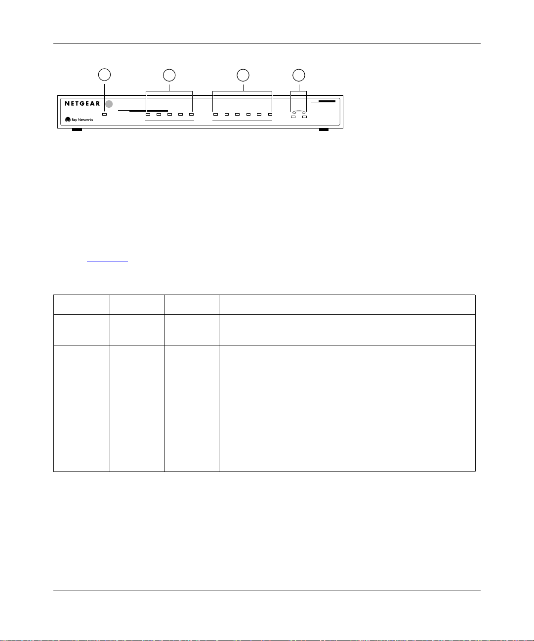
Reference Guide for the Model XM128 ISDN Digital Modem
1
2 3 4
INTERFACE
U
128Kpbs
ISDN Digital Modem
ISDN
DTR DSR RTS CTS TDDPWR B1 B2 AA CP
RD
COM
12
MODEL
XM128
7847MEA
Key:
1 = PWR (power) LED
2 = ISDN LEDs
3 = RS-232 COM LEDs
4 = PHONE 1 and PHONE 2 LEDs
Figure 1-2. Fr on t panel of the Model XM128 modem (with U interface)
LEDs on the front panel of the Model XM128 modem allow you to monitor and diagnose the
device. Table 1-2 des cribe s each LED.
Table 1-2. LE D de scriptions
Label Color Activity Description
PWR
(Power)
ISDN LEDs:
D Green On The ISDN link on the D channel is active.
B1 On A connection is establ ished to the B1 channel.
B2 On A connection is establ ished to the B2 channel.
AA On The Model XM128 modem is in the automatic answering mode.
CP Blinking An incoming call is ringing.
Yellow On Power is supplied to the modem.
Blinking The modem is attempting to make a connection to the switch.
On Compression is active on either of the B channels.
1-4 Introduction
Page 25

Reference Guide for the Model XM128 ISDN Digital Modem
Table 1-2. LE D des criptions ( continued)
Label Color Activity Description
COM LEDs:
DTR Green On The data terminal or computer connected to the COM port on
the Model XM128 modem is ready to communicate.
DSR On The Model XM128 modem is ready to communicate wit h the
connected data termin al or computer.
RTS On The data terminal or computer connect ed to the COM port on
the Model XM128 modem is ready to transmit data.
CTS On The Model XM128 modem is ready to accept data from the
connected data termin al or computer.
TD Blinking The data terminal or computer connected to the Model XM128
modem is transmitting data to the modem.
RD On The data terminal or computer connected to the Model XM128
modem is receiving data from the DTE port of the modem.
PHONE 1 On The handset of the telephone connected to the port is not
properly placed in the receiver cradle.
PHONE 2 On The handset of the telephone connected to the port is not
properly placed in the receiver cradle.
Introduction 1-5
Page 26
Reference Guide for the Model XM128 ISDN Digital Modem
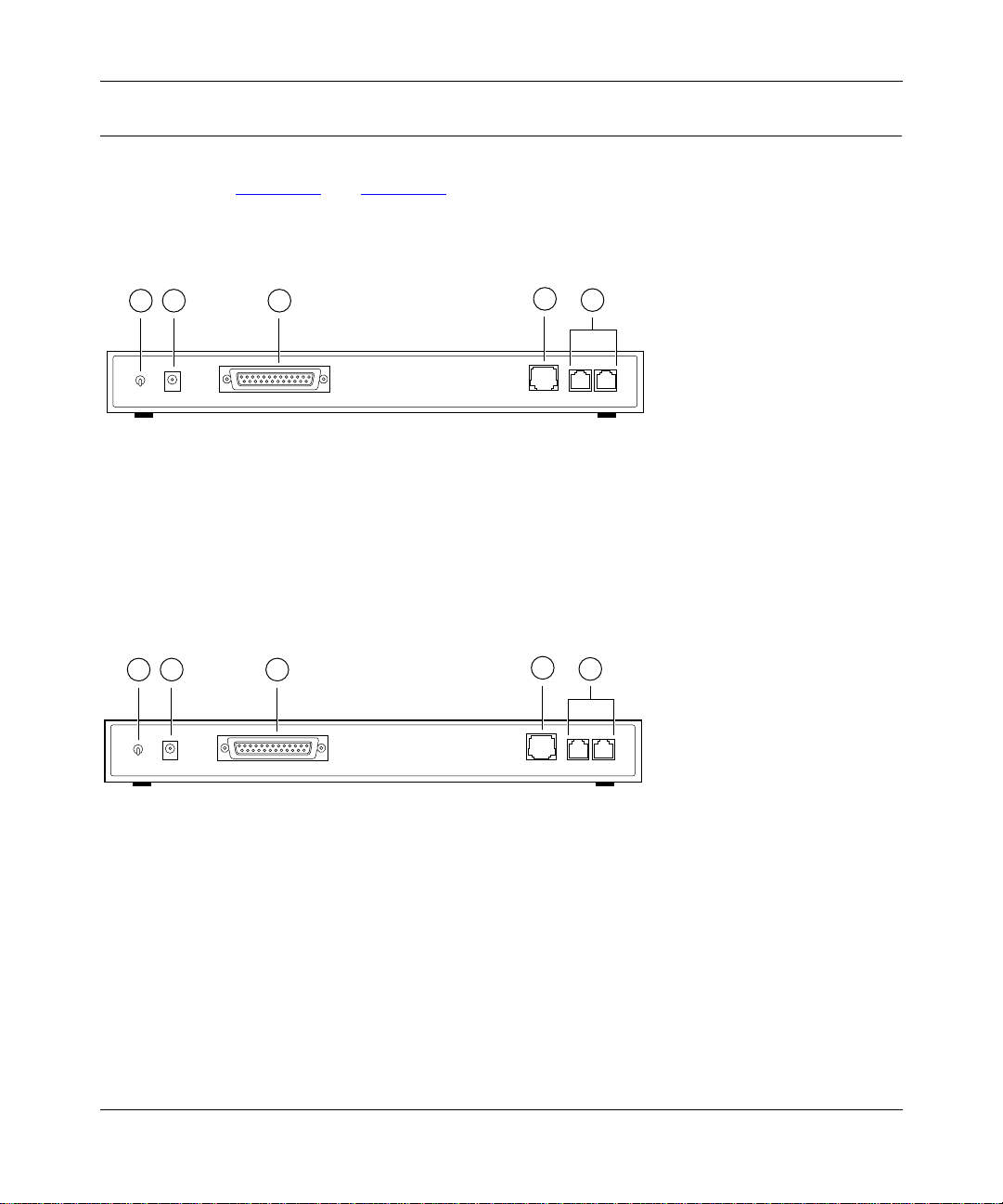
Rear Panel
As illustrated in Figure 1-3 and Figure 1-4, the rear panel contains a power switch, a power
receptacle, and ports to connect a computer, ISDN line, and two analog devices (phone, fax, or
modem).
4
1 2 3
5
ON/OFF
POWER
RS-232
ISDN-S
PHONE 1PHONE 2
7861MEA
key:
1 = ON/OFF switch
2 = Receptacle for power adapter
3 = RS-232 COM port for connecting to a computer
4 = ISDN port for connecting to an ISDN line NT-1
5 = PHONE 1 and PHONE 2 ports for connecting analog de vices (telephone , fax, or modem)
Figure 1-3. Rear panel of the Model XM128 modem (with S interface)
4
ISDN-U
5
PHONE 1PHONE 2
7862MEA
1 2 3
ON/OFF
POWER
RS-232
Key:
1 = ON/OFF switch
2 = Receptacle for power adapter
3 = RS-232 COM port for connecting to a computer
4 = ISDN port for connecting to an ISDN line
5 = PHONE 1 and PHONE 2 ports for connecting analog de vices (telephone , fax, or modem)
Figure 1-4. Rear panel of the Model XM128 modem (with U interface)
1-6 Introduction
Page 27

Reference Guide for the Model XM128 ISDN Digital Modem
Table 1-3 describes the components on the rear panel of the Model XM128 modem.
Table 1-3. Rear panel components
Label Description
ON/OFF This switch turns power on or off.
POWER This is the power receptacl e for the power adapter.
RS-232 This RS-232 COM port is for connec ting the Model XM128 modem to the serial port
of a computer or data terminal.
ISDN This port is for connecting the RJ-45 connector of an ISDN line.
PHONE 1 This port is for connecting the RJ-1 1 connector of an analog device (telephone, fax,
or analog modem).
PHONE 2 This port is for connecting the RJ-1 1 connector of an analog device (telephone, fax,
or analog modem).
Introduction 1-7
Page 28

Page 29

Chapter 2
Installation
This chapter informat ion abo ut installing and using the Model XM128 ISDN Digital Modem.
Package Co n t e n t s
Your package should contain the following items:
• Model XM128 ISDN Digital Modem
• Power adapter
• RJ-45 ISDN telephone cable
• Shielded RS-232 25-pin to 25-pin cable
• 25-pin to 9-pin adapter
• This manual
• Getting Started Using FirstGear
• CD ROM with bundled software
• 3.5-inch driver and uti lity diskettes
• Warranty Registration Card
Call your reseller or customer support in your area if there are any wrong, missing, or damaged
parts. Refer to pag e iii for the location of customer support in your area.
Keep the carton , inc luding the original packing materials. Use them to repack the modem if you
need to return it for repair.
Installation 2-1
Page 30
Reference Guide for the Model XM128 ISDN Digital Modem
To qualify for product updates and prod uct warranty registrations, fill in the Warranty and Owner
Registration Card within 30 days of purchase and return it to NETGEAR, Inc.
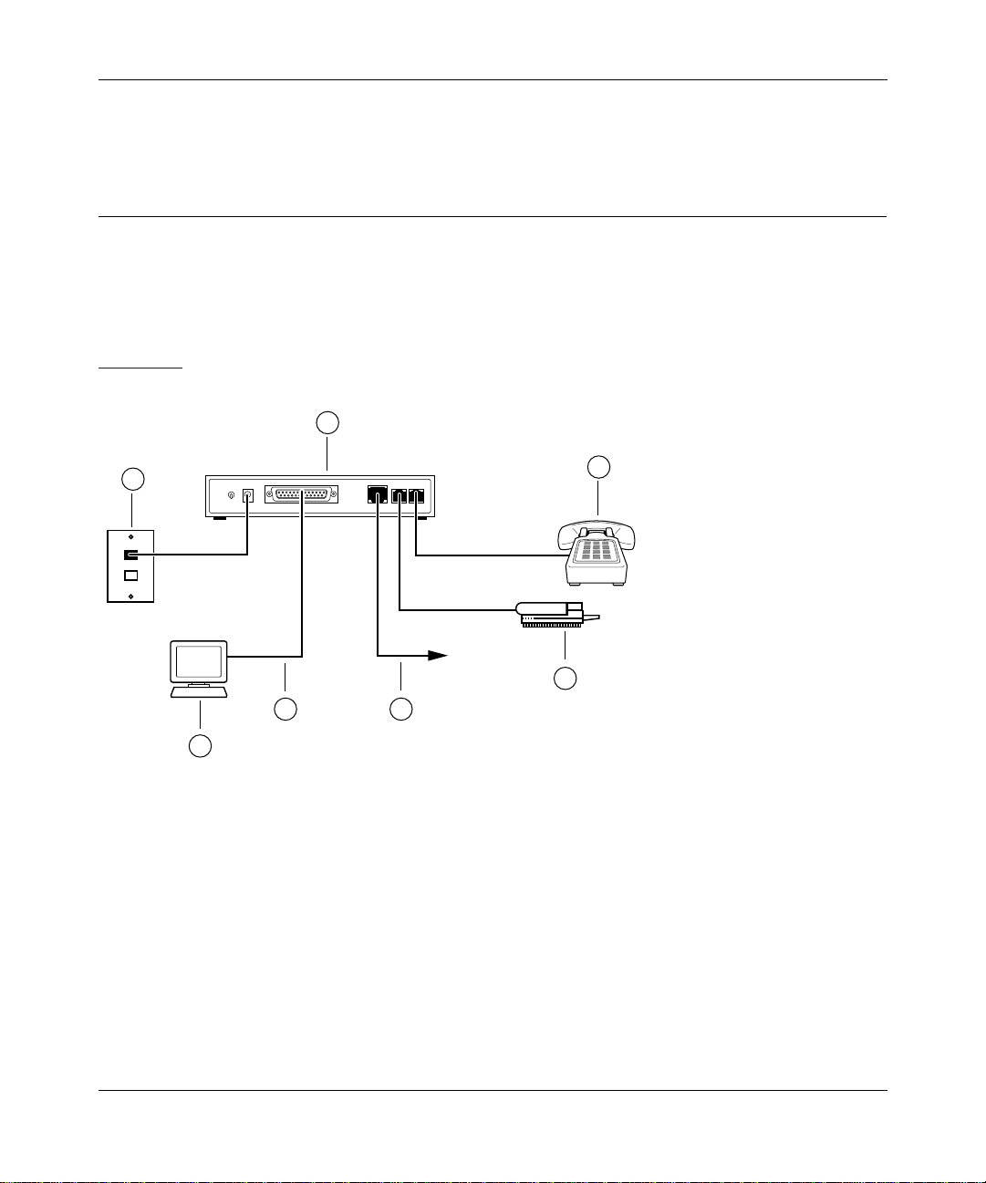
Installing the Modem
Before connecting any of the devices to your modem, make sure the powe r is turne d off on your
computer and your Model XM128 modem. If connecting to the model with the S/T interface, you
must use an NT-1 device, whic h converts the S/T interface to a U interface. If connecting to the
Model XM128 modem with the U interface, you can connect directly to your ISDN line. Refer to
Figure 2-1
and then the detailed steps that follow for making those connections.
1
2
4 5
3
Key:
1 = Model XM128 modem
2 = AC power adapter
3 = Station (PC, Macintosh, or UNIX workstation)
4 = Shielded RS-232 25-pin straight cable
5 = ISDN wall connection (connected with ISDN cable provided in package)
6 = Analog device (telephone or fax)
Figure 2-1. Model XM128 modem connections
6
6
7860MEA
2-2 Installation
Page 31

Reference Guide for the Model XM128 ISDN Digital Modem
To install your Model XM128 modem, follow the se steps:
Connect the male end of the 25-pin cable to the RS-232 COM port of the Model XM128
1.
modem.
Connect the other end of the 25-pin cable (female end) to the seria l (COM) port on y our
2.
computer.
If your computer has a 9-pin serial connector, use a 25-pin to 9-pin converter
Note:
(25-pin male to 9-pin female) . If you ha ve a Macintosh, a special cable is needed for the
connection.
Using the ISDN cable that is included, connect the RJ-45 connector on one end of the
3.
cable to the ISDN port on the back of the Model XM128 modem.
For European models, connect the other end of the RJ-45 ISDN cable to your NT-1
4.
terminal or S/T interface. Using the proper cable supplied wi th your N T-1, connect your
NT-1 or U interface to the wall jack installe d by your phone company.
For North American models, connec t the other end of the RJ-45 ISDN cable to the wall
5.
jack install ed by your pho n e co m pany.
Using the proper cable, insert the round end of the power adapter in the POWER
6.
connector on the rear panel.
Plug the power supply unit into an AC wall outlet.
7.
Turn the power on to your Model XM128 modem.
8.
Turn the power on to your computer.
9.
Verifying Hardware Installation
When the installation is complete and power applied to the modem, a self-test sequence begins.
The B1, B2, and AA LED lights blink on and then of f aga in. Aft er this cycle is complete, the PWR
(power) LED remains on.
If the test routine fails, the D LED blinks. Refer to Chapter 10, “Troubleshooting,” for more
information about the self-test and the error codes.
Installation 2-3
Page 32

Page 33

Chapter 3
Setup for Windows 95 and Windows NT 4.0
This chapter contains step-by-step procedures both for installing the Windows NT and
Windows 95 drivers and for configuring Dial- Up Networking for the Model XM128 modem.
Selectin g the Ap propriate Windows 95 Driver (INF file)
If your computer supports the Plu g-and- Play feature, be sure your Model XM128 modem is
powered on before starting your computer. If you are using a non-Plug-and-Play protocol, follow
the steps to complete installation:
Open the Contr ol Panel by double-clicking the Control Panel icon in your My Computer
1.
folder.
Double-click on Modems.
2.
Click on Add.
3.
The Install New Modem screen appears.
Select Don't detect my modem; I will select from a list.
4.
Click on Next.
5.
Click on Have Disk.
6.
Insert the NETGEAR Windows 95 driver disk into your floppy drive and click on OK.
7.
If you have downloaded an updated INF file fro m NETGEAR’s Web site or BBS, use
8.
Browse to find the location of the updated INF file, click on Open, then click on OK.
Setup for Windows 95 and Windows NT 4.0 3-1
Page 34

Reference Guide for the Model XM128 ISDN Digital Modem
Select the Model XM128 modem driver with the protoc ol that your host is using.
9.
Generally, the followin g examples work. However, we recommend that you verify
the protocol your Internet service provider (ISP) uses.
If you are connecting to an Internet service provider (ISP), select:
NETGEA R XM1 28 , PP P 64K
If the ISP has not upgraded to an ASCEND compatible server, select:
NETGEAR XM128 V.120 64K
If you are calling another location such as a BBS system, select:
NETGEAR XM128 V.120 64K
If you dial up to CompuServe, select:
NETGEAR XM128 V.120 64K
If you are calling the Microsoft Network (MSN) ISDN line, select:
NETGEA R XM1 28 , PP P 64K
After you have completed the selections above, click on Next.
10.
Select the COM port your modem is connected to and click on Next.
11.
A final dialog box will appear.
Click on Finish.
12.
The Modems Properties screen is displa yed.
Click on Close.
13.
This step completes the installation of your Model XM128 modem driver. You may now
use programs such as Dial-Up Networking with your modem.
3-2 Setup for Windows 95 and Windows NT 4.0
Page 35

Chapter 4
Configuration
This chapter describes the procedure s f or configuring your Model XM128 modem and your ISDN
line.
Configuring Your ISDN Line and Network
The setup procedure for the Model XM128 modem needs to be done only once. The settings are
stored in the nonvolatile random access memory (NVRAM) of the modem. Turning power on and
off wil l not e rase the info rmation. The only time that you need t o reconf igure your l ine is when you
perform a hard wa re reset on yo ur mod em w hen you chan g e op tions on your ISDN line.
NETGEAR provides a simple W indows 95 or NT 4.0 utility to help you set up the Model XM128
modem. Refer to
complete instruct ions. This chapter explains how to se t up your switch using the Windows/
Windows 95 utility that comes with the modem.
Getting Started Using FirstGear for the XM128 ISDN Digital Modem
for
If your Model XM128 modem is not going to be set up by a computer running W indows, use
a terminal prog ram that allows you to send AT commands to the modem and receive responses
from it.
Configuring Your Modem Using a Terminal Program
If you are not running W indows 95 or Windows NT, configure your Model XM128 modem with
a terminal prog ram that allows you to send and receive AT commands and responses from the
modem.
NETGEAR recommends that you have your Model XM128 modem ready to use before the
telephone compan y insta lls your ISDN line. If the modem is ready, you can enter the SPID and
confirm that the ISDN network is responding properly before the telephone installer leaves.
Configuration 4-1
Page 36

Reference Guide for the Model XM128 ISDN Digital Modem
The setup procedure for the Model XM128 modem needs to be done only once because the
settings are store d in the nonvolati le RAM of the modem and turning the power off does not erase
the information. The only time you have to reconfigure your line is when you perform a hardware
reset or when you change options on your ISDN line.
If you perform a har dware re set a nd ha ve to re ente r the SPID nu mber(s) and swi tc h
Note:
type again, it is easier if you write down or store all the relevant information so it can be
easily retrieved.
Table 4-1 shows a list of example terminal programs for different operating platforms. For
instructions on how to use a terminal pr ogram, refer to the instru ctions tha t came with the progr am.
T able 4-1. Terminal programs
Operating system Program
Windows 95 Hyper Terminal
Windows 3.x Terminal
Procomm Plus for Windows
Qmodem for Windo ws
UNIX Minicomm
DOS PC Plus
Qmodem
Macintosh Z-T erm
Communicate Lite
Understanding AT Commands
AT commands configur e and control the Model XM128 modem through a terminal program.
Command statements are usually sent to the modem from the computer keyboard.
Command statements must be written in a specific form in order f or the Model XM128 modem to
recognize them. A command statement begins with the letters AT or at. It is then followed by one
or more commands and the Enter key.
AT commands can be issued only when the Model XM128 modem is in command or of f li ne mode.
After the Model XM128 modem has established a connection with the remote device, it goes into
online mode, and the characters sent from your computer (through the modem) are transmitted
to the remote device.
4-2 Configuration
Page 37

Reference Guide for the Model XM128 ISDN Digital Modem
In order to issue an AT command statement, you first need to run your communications software
and configur e it to t he port c onnect ed to th e Model XM128 modem . Refer to your communications
software manual for more information.
Table 4-2
Table 4-2. S upported AT comma nd t ypes
Type of AT command Example
Basic AT (Hayes compatible) ATA
Basic AT$ (online Help) AT$
Extended AT& AT&F
Extended AT* command AT*I1
S-Register command ATS0=1
S-Register bitmapped command
(set S-Register bit 1 equal to 1)
Register inquiry command SA TS0? or ATS13.1?
lists the supported AT command types.
ATS13.1=1
You can also browse the list by using the command AT$.
Quick Tips for Issuing AT Comm ands
The followi ng is a list of quick tips when issuing AT commands:
• The [Enter] key must be pressed to exec ute a command.
• Multiple AT commands can be combined into one line (for example, AT&O2 and ATB02 are
combined as follows: AT&O2B02).
• The Model XM128 modem processes commands from left to right. The AT command that
appears to the right might overwrite the command to the left (for example, ATB13B14 results
in ATB14 because both B13 and B14 cannot coexist).
• If you see duplicated characters for each one you type, your Model XM128 modem and
software both have their echo feature turned on (the modem def aults to enable command
echo). To eliminate the doubl e chara cters, turn off softwar e command echo.
• Use A/ to repeat the last command. No AT prefix is needed for this command.The Model
XM128 modem supports either verbose result code (OK, for example) or numerical result
code (0, for example). You can use the ATVn command to set it one way or the other.
Configuration 4-3
Page 38

Reference Guide for the Model XM128 ISDN Digital Modem
Table 4-3 lists the commands for viewing both the numerical and ver bose result codes.
Table 4-3. Result codes commands
Command Description
ATV0 Select numerical result code
ATV1 Select verbose result code
Using AT Commands to Verify Modem Response
Use AT commands to make sure the Model XM128 modem responds, and follow these steps:
Type the command AT and press [Enter].
1.
You should receive the following response:
OK
Type the command ATI and press [Enter].
2.
You should receive the following response:
1291
Type the command ATI1 and press [Enter].
3.
You should receive the following response:
NETGEAR XM128 ISDN Digital Modem xxxx: V x.xx
7607
OK
In the first line, x designates the country or region of operation and the firmware version
number. The second line is the firmwa re chec ksum (which changes based on your firmware
version).
Communication Speed Setup
Make sure the program is se t up to c ommunicat e with th e COM port tha t is conne cted to t he Model
XM12 8 m o dem. I n m o s t c ases, when th e termin a l progr a m is active a n d r ea d y to c o m m u ni cate
with the connected port, the DTR signal is activated and the DTR LED lights. If the DTR LED is
off, check the terminal program settings.
The communication speed can be set between 110 bits per second (bps) and 460.8 bps, but 115.2
bps is a good default value. The Model XM128 modem automatically adjusts its speed to match
the communication speed you set.
4-4 Configuration
Page 39

Reference Guide for the Model XM128 ISDN Digital Modem
Switch Type Setup for North America
In North America, the popular types of switches are AT&T 5E SS , Nor the rn Telecom DMS1 00,
and Siemens EWSD. All of these switches run software that either conforms to the National
ISDN-1 standard or a custom version. The Model XM128 modem supports the six different
combinations listed in Table 4-4
. The value for n in the ATPn command is shown in the AT
command column. The ATPn command programs the D channel protocol so that the Model
XM128 modem works with the type of switch that is connecte d to your ISDN line.
T able 4-4. Switches supported by the Model XM128 modem
ISDN network switch Switch version AT command Number of SPIDs
AT&T 5ESS network switch Point-to-point Protocol ATP4 0
Point- to-multipoint Protocol ATP5 1
Point- to-multipoint Protocol ATP6 2
National ISDN-1 ATP1 1
National ISDN-1 ATP2 2
NT DMS 100 network switch Custom ATP0 2
National ISDN-1 ATP1 1
National ISDN-1 ATP2 2
Siemens EWSD network switch National ISDN-1 A TP1 1
National ISDN-1 ATP2 2
Other National ISDN-1 ATP1 1
National ISDN-1 ATP2 2
To set your switch type, use AT commands (examples given are if your switch type is DMS 100
with Custom Protocol) and follow these steps:
T ype ATP0 and press [Enter].
1.
You should receive the following response:
OK
Switch Type: Northern Telecom DMS 100
T ype AT&WZ and [Enter] to save the settings.
2.
You should receive the following response:
OK
Configuration 4-5
Page 40

Reference Guide for the Model XM128 ISDN Digital Modem
SPID Setup for North America
SPID numb ers are n eed e d un les s yo ur switch type is AT&T 5ESS with Point-to-Point Protocol.
The ISDN switches use SPID numbers to represent the subscribed network services. Each SPID
corresponds to one terminal e nd point identifier. Different switches might provide different rules
for the SPID n umber for mat. You should get the SPID number f rom your loca l t elephone company.
To program your SPID number(s), use AT commands (n is the SPID provided by your telephone
company) and follow these steps:
T ype ATSPIDO=n and [Enter].
1.
You should receive the following response:
OK
SPID Correct!
It might take up to 30 seconds for the response. This response indicates that the SPID number
was accepted. If a second SPID is required, go to step 2.
T ype ATSPID1=n and [Enter].
2.
You should receive the following response:
OK
SPID Correct!
An error condition is present and it indicates that an incorrect SPID number was entered if you
receive the following response:
OK
SPID Error!
A general failure is indic ated if the ISDN line is not connected to your Model XM128 modem or
if you select the wrong switch. The SPID number was not verified if you receive the follo wing
response:
OK
The D LED lights when the SPID(s) are entered and verified. If you are not able to get the SPID(s)
to accept correctly, recheck all cable connections before verifying the number(s) with your
telephone compan y and reente ring them again. If the D LED still does not light, the telephone
company should make sure the lin e you ordered has been correctly set up.
4-6 Configuration
Page 41

Reference Guide for the Model XM128 ISDN Digital Modem
Entering DNs
You will need to enter the phone numbers given to your ISDN line. The phone numbers will be
cleared whenever the switch type is changed.
Type ATDN0=n and [Enter].
1.
Where n is the 7-digit phone number.
You should receive the following response:
OK
Type ATDN1=n [Enter].
2.
Where n is the second 7-digit phone number.
You should receive the following response:
OK
T ype AT&W0Z0 and [Enter] to save the settings.
3.
You should receive the following response:
OK
Setup for Europe and the United Kingdom
To configure your Model XM128 modem for Europe and the United Kingdom, follow these steps:
Type the command AT&ZOI= and the ISDN telephone number to assign the outgoing
1.
telephone numbers.
For example, AT&ZO=5551111
Press [Enter].
2.
Type the command AT&ZOA= and the outgoing telephone number for PHONE 1.
3.
For example, AT&ZOA=5552222
Type the command AT&ZOB= and the outgoing telephone number for PHONE 2.
4.
For example, AT&ZOB=5553333
Assign a protocol using the commands in Table 4-5 to configure the B channel protocol .
5.
Configuration 4-7
Page 42

Reference Guide for the Model XM128 ISDN Digital Modem
Table 4-5. AT commands for sett in g protocols
Protocol AT command
X.75 ATB00&O2
V.110 user rate - 38400 bps ATB18&O2
V.120 ATB20&O2
PPP ATB40&O2
For example, if the protocol you want is PPP, type the command A TB40&O2. For other X.75
or V.110 protocol options, refer to Appendix C, “AT Command Set Reference.”
Assign the appropriate MSN telephone numbers, using the AT commands in Table 4-6.
6.
Table 4-6. AT commands for setting MSN
Multiple subscriber number AT command
X.75 telephone number AT&ZI0=telephone number
V.110 telephone number AT&ZI1=telephone number
V.120 telephone number AT&ZI2=telephone number
PPP telephone number AT&ZI3=telephone number
ISDN Data (Protocol autodetection) AT&ZI4=telephone number
PHONE 1 AT&ZI6=telephone number
PHONE 2 AT&ZI7=telephone number
For example, to assign an MSN number for a V.120 call, type the command AT&ZI2=5553434.
Type the AT command AT&W0Z0 to store the information into NVRAM.
7.
4-8 Configuration
Page 43

Chapter 5
Async to Sync PPP
This chapter describes the application of asynchronous to synchronous HDLC conversion.
Internet and Remote Ac cess PPP and SLIP
More and more Internet Service Providers are offering their services through dial-up ISDN lines
for higher data bandwidth. The equipment used by your service provider fre quently consists of
ISDN LAN routers which, unlike a digita l modem, do not have asynchronous capability. For this
reason, terminal adapters that support only V.120 or asynchronous protocol do not work with this
type of equipment.
The Model XM128 modem conv erts the asynchronous data it receives from your computer to
synchronous format in order to co mmunicate with ISDN LAN routers. We call this process
asynchronous to synchronous HDLC conversion or Async to Sync PPP (Point-to-Point Protocol)
or Async to Sync Serial Line Internet Protocol (SLIP) protocol.
Making Async to Sync PPP and SLIP calls
In order to communicate with an ISDN LAN router (fr om vendors such as Ascend and Cisco), set
the Model XM128 modem B channel protocol to one of the following:
ATB40<Enter> (
or
ATB41<Enter>(
You should also set the DTE speed based on the bandwidth that the switches support.
Async to Sync PPP 5-1
HDLC PPP
HDLC SLIP
)
)
Page 44

Reference Guide for the Model XM128 ISDN Digital Modem
Most of the time, you only use this protocol for making calls to remote sites with ISDN LAN
Routers. If the remote access site you are calling uses a Te rminal Adapter such as the
Model XM128 modem, you can use V.120, as it provides data compression.
Before making the call, check which prot ocol is set for the I SDN mode using the &V command to
view the settings.
When you are ready to view the settings type:
AT&V<Enter>
The Model XM128 modem modem responds:
Current Settings...
Switch Type: Northern Telecom DMS
ISDN Outgoing Service: PPP Async-to-Sync Conv 64K
If the settings displ ayed match your current setup, you are ready to place the call.
When you are ready to place the call type:
ATDI<remote_access_number><Enter>
The Model XM128 modem responds:
Connect 115000/64000 PPP/None
Keeping a Line Connection During Idle Time
If you are using PPP to access a server the server probably has a watchdog timer to monitor the
line activity. If the idle time exceeds some time interval (usually 1 minute), the server releases the
connection for other cl ien ts to dial in. Users may suffer some inconvenience because you ha ve to
dial to the server again an d repeat the login procedure when disconnected. The value in register
S124 (in seconds) is used as the idle time gauge. If the idle time exceeds this guarding period, the
Model XM128 modem sends out a dummy PPP packet to the server to keep it from disconnecting
the line.
Example: If the server you are cal ling disconnects after 1 minute of inactivity , issue the following
command before connecting:
ATS124=59<Enter>
(send dummy PP P packet after 59 seconds of ina ctivity)
Setting S124=0 disables this function.
5-2 Async to Sync PPP
Page 45

Reference Guide for the Model XM128 ISDN Digital Modem
Answering Async to Sync PPP calls
There is no need to configure the ISDN mode to the protocol of an incoming call. If it is set to
auto-answer or an answerin g command is issue d, the Model XM128 modem determine s the
correct protocol to use by examining the data coming in from the remote site. One exception is
when the ISDN data call is carried through a Speech bearer. In this case you would need to set up
an MSN for the phone number of the calling party. To do this, use the command AT&ZI3=xxx;
xxx
where
For the Model XM128 modem to automaticall y answer incoming calls, you need to set S0 to a
value greate r than 0 (i.e. ATS0=1). The Model XM128 modem answers the call and uses
asynchronous to synchronous conversions to and from the DTE. If S0 is not set (S0=0), the DCE
reports RING and also makes an audibl e ring notification.
Multilink PPP
Multilink PPP (MPPP) is a protocol that allows virtual bundling of the two B channels allowing
connection speeds of 128Kbps . MPPP suppor t is a standa rd feature of the Model XM128 modem.
is the number from which the call originates.
Making a call using Multilink PPP
A Multilink PPP conne ction is init iated at the c alling s ite when ATB40 (B channel protocol HDLC
PPP) has been selected and the Multilink PPP mode has been enabled by an AT&J
AT&J0 (disables Multilink PPP)
AT&J1 (enables Multilink PPP in answer mode only)
AT&J2 (enables Multilink PPP in call mode only)
AT&J3 (enables Multilink PPP in both call and answer modes)
n
command:
By default, the Model XM128 modem dia ls the same number for both Multilink PPP connections.
If the destination you are dialing requires two different telephone numbers to establish a two
channel Multilink PPP connection, then the following command can be used:
ATDIphone_number_1+phone_number_2
The phone numbers of the destination a re det ermined by the commands: phone_number_1 and
phone_number_2 are the phone numbers of the destination.
If the destination r efuses the Multilink PPP during the Link Control Protocol (LCP) negotiation, a
single B channel PPP connection is est abl ished. The connection message is the same whether the
Multilink PPP connections have been established or not.
Async to Sync PPP 5-3
Page 46

Reference Guide for the Model XM128 ISDN Digital Modem
Dialing Pre-stored Phone Numbers
The ATDSn command, n=0,1,..,3 9, dials the (n+1)th phone number twice for both of the Multilin k
PPP connections. The command ATDSn+Sm, (n and n=0,1,...,39) dials the (n+1)th phone number
for the first co nnection and the (m+1)th phone number for the second connection.
Example : ATDIS0+S1 [Enter] dial s the number stored in lo cation 0, and the number stored in
location 1 for the MPPP connection.
Endpoint Discriminator
The Endpoint Discrim inator option represents identification of the system transmitting the packet.
This option advises a system that the peer on this link could be the same as the peer on another
existing link. Some Multilink PPP implementations require the use of the Endpoi nt Discriminator
option.
The Endpoint Discriminator consists of two components: Class and Address.
The Class field is one octe t as stored in S-register S85 and indicates the identifier address space.
Table 5-1
lists the vali d values of the S85 register.
Table 5-1. S85 register values
Value Description
0
1
2
3
4
5
Null Class (by defa ult).
Internet Protocol (IP) Address
IEEE 802.3 Globally Assigned MAC Address.
Locally Assigned Address.
PPP Magic-Number Block.
Public Switched Network Dir ector y Number.
The Endpoint Discriminator Address field is of variable length from 0 to 20 octets and can be
assigned by the ATEPD command:
ATEPD = <Octet_1,Octet_2,Octet_3,..,Octet_n>
5-4 Async to Sync PPP
Page 47

Reference Guide for the Model XM128 ISDN Digital Modem
Each Octet_i is in the range from 0 to 255. The angle brack et s (<) and (>) are par t of the this
command. The command ATEPD? can be used to view current setting of the Endpoint
Discriminator Address.
The Endpoint Discriminator option is not required in most cases, thus users don't
Note:
have to chang e the defa ult settings. The system administrator of your corporate or the
Internet service provider provides these values if the Endpoint Discriminator option is
required.
Call Bumping Dynamic Channel Allocation
When call bumping, Dynamic Channel Alloc ation ( DCA) is enabled (by de fau lt), you can place or
answer a voice call (and only one ) from a de vic e that i s attached to one of the phone ports . The call
can be placed while a Multilink PPP call is active. The Model XM128 modem automatically
removes one of the Multilink PPP connections and uses it for the voice call. When the voice call
ends, the Model XM128 modem automatically reestablishes that channel for Multilink PPP
operation. The call bumping DCA function is only ef fective when the Model XM128 modem is at
the calling site (the client site). The following command can be used to select the DCA function:
ATCE0 (disables call bumping)
ATCE1 (enables call bumping by default)
Async to Sync PPP 5-5
Page 48

Page 49

Chapter 6
ISDN Overview
This chapter covers the procedures for initiating and receiving calls over digital lines using your
Model XM128 ISDN Digital Modem.
Commands for Outgoing Calls
The Model XM128 modem uses the following thre e modes to send communication over your
ISDN network:
• ISDN data
• Analog port, PHONE 1 communication
• Analog port, PHONE 2 communication
These modes are automatically switched based on the commands you issue. To understand this
process, use your terminal program and proceed with the instructions explained in the following
sections.
Dialing Out Using ISDN Mode
The command ATDI tells your Model XM128 modem that you want to make an ISDN data call
and to therefore use the ISDN mode to call out. Enter :
ATDI17142630398
This command initiates an ISDN call.
ISDN Overview 6-1
Page 50

Reference Guide for the Model XM128 ISDN Digital Modem
Dialing Out Using ISDN Mode Optional Speech Bearer Service
The Model XM128 modem supports ISDN data utilizing Speech Bearer Service. To enable this
function, you need to set S-register S83 bit 7 to 1 (ATS83.7=1). This function is useful in the areas
where ISDN service provi ders c harge lower usage rate s for voice (speech) calls. To enable this
function, enter:
ATS83.7=1
To disable it, enter:
ATS83.7=0
Dialing Out for Analog Adapter Port 1
Using the A command followin g the ATD tells your Model XM128 modem to switch the call to
analog adapter port PHONE 1, when dialing is comple te. Enter:
ATDA17146930762
You must have an analog modem connected to your plain old telephone service
Note:
(POTS) port before you issue this command.
Dialing Out for Analog Adapter Port 2
Using the B command following the ATD tells your Model XM128 modem to automatically
switch the call to analog adapter port PHONE 2, when dialing is complete. Enter:
ATDB17146930762
Manually Switching Communication Modes
The manual switching function is ne cessary only if your communication software does not allow
you to change your dial-up string.
6-2 ISDN Overview
Page 51

Reference Guide for the Model XM128 ISDN Digital Modem
Conventional dialing commands ATD, ATDT, and ATDP, used by much of the existing
communication softw are, can be mapped onto one of the new dialing commands according
to the AT&O setting as shown in Table 6-1
T able 6-1. Dialing commands
AT Command Dial string it maps to
AT&O0 A TD, ATDT, and ATDP are the same as ATDB.
AT&O2 A TD, A TDT, and ATDP are the same as ATDI.
AT&O3 A TD, A TDT, and ATDP are the same as ATDA.
.
The factory defa ult is AT&O2, which means that the Model XM128 modem selects ISDN data
mode when you do not specify the communication mode to use (that is, ATD or ATDT).
Placing the Call
To initiate a call, choose the proper communication mode and configure the mode according to
the bearer servi ce (or pro toc o l) you want to use. Table 6-2 contains some simple commands that
are useful when placing a call.
T able 6-2. Call placing commands
Command Description
ATBnn Changes ISDN B channel protocol setting
ATDL Redials the last dialed telephone number
ISDN Overview 6-3
Page 52

Reference Guide for the Model XM128 ISDN Digital Modem
Comma nds for Inco ming Calls
When a call comes in, the call is carried by one of the following protocols:
• V.120
• HDLC PPP, MPPP, or SLIP
• V.110
•X.75
Or the call may be initiated by an analog device.
This section provide s some general guidelines for setting up the Model XM128 modem for call
answer handling. Be aware that the modem does not automatically answer a call unless S-register
S0 is set to a value greater than 0 (zero). If S-register S0=0, the modem only reports RING to your
terminal progr am. It can also respond with a n audi ble tone that a llo ws you to dec ide whethe r or not
you should take any action.
When an ISDN data call comes in, the Model XM128 modem tries to negoti ate a connection using
the proper ISDN protocol. When an analog call co mes in, the modem sends the call to the analog
port as the factory default, PHONE 1, and then PHONE 2.
Digital Data
The Model XM128 modem currently supports Circuit Switched Data (CSD) for ISDN data
applications. The CSD protocols supported by the Model XM128 modem include: PPP, MPPP,
V.120, X.75, and V.110. PPP is the most popular protocol used in North America; it is used by
most of the Internet servic e provide rs. Afte r the Model XM128 modem answers a call, it e xamines
the incoming data to determine which protocol to use and automatically switches to that mode.
This process occurs tra nsparent ly to the user. The Model XM128 modem is able to auto-switch for
PPP, MPPP, V.120, X.75, and V.110 protocols ov er spe ech channel. In most cases, you can rely on
the auto-switchi ng feature for your applications. If you need more specific settings for answering
calls, refer to “Answering a Call Using MSN
6-4 ISDN Overview
” on page 5-5.
Page 53

Reference Guide for the Model XM128 ISDN Digital Modem
Determining the Packet Length
The user’s information is sent on a frame-by -frame basis for V.120 and X.75, sometimes called
packetized. The maximum frame length on the sending side should not exceed the maximum
frame length that the receiving side allows. Sometimes this information is exchanged during
handshaking. However, few manufacturers, if any, have implemented this mechanism.
If the sending side sends packets greater than what the receiving side allows, the receiving side
discards the fram e an d repl ie s with a Frame Reject Frame (FRMR). The FRMR indi cates tha t the
information received is too long. Both sides then reset their link layer negotiation and send the
frame again. Usually this process repeats until the call gets disconnected.
The Model XM128 modem has a fixed maximum receiving frame size of 2048 octets, whic h is
larger than most devices can support. The default maximu m sending fra me size is 252 octets for
V.120 and 2048 for X.75. If you need to change the maximum sending frame size, the ATCL
command is used.
To change the maximum sending frame size, use the following commands and follow the se steps:
Enter ATCL252 (set the frame size to 252 octets, user value between 1 and 2048).
1.
You should receive this message:
OK
Enter ATCL? (to inquire about the current setting of the packet length).
2.
You should receive this message:
Maximum user data length in a packet (byte) : 252
ISDN Overview 6-5
Page 54

Reference Guide for the Model XM128 ISDN Digital Modem
Answering a Call Using MSN
When answering an incoming call, the call is first identified if the caller number matches the
Multiple Subscriber Number (MSN) settings.
The MSN supplementary service enables multiple ISDN numbers to be assigned to a single
ISDN BRI line. It allows the caller to select, through the public net work, one or more distinct
terminals from a variety of terminal choices. The Model XM128 modem supports many different
communication protocols and two analog adapters. Table 6-3
each of the ports to an ISDN number.
Table6-3. C ommands for assigning ISD N numbers
Command Description
&ZI0=s Assigns the MSN phone number for X.75
&ZI1=s Assigns the MSN phone number for V.110
&ZI2=s Assigns the MSN phone number for V.120
&ZI3=s Assigns the MSN phone number for PPP, MPPP
&ZI4=s Assigns the MSN phone number for ISDN data,
protocol auto-detection
shows the commands used to assign
&ZI5=s Assigns the MSN phone number for PPP, MPPP
&ZI6=s Assigns the MSN phone number for Phone 2
&ZI7=s Assigns the MSN phone number for Phone 1
The command AT&ZI? can be used to display the MSN numbers. The factory default for these
numbers is UNASSIGNED.
6-6 ISDN Overview
Page 55

Reference Guide for the Model XM128 ISDN Digital Modem
If an incoming s etup message is offered wi th ad dre ssing information (that is, the appropriate part
of the Called Party Num b er), this address is compared with the MSN numbers assigned by the
AT&ZIn=s commands. The call is accepted using the specific protocol if the assigned number of
this protocol matches the rece ived Called Party Number.
You are not required to enter the complete numbering string for the AT&Z
Note:
command. The last few distinguishable digits are enough for the XM128 to make the
decision. Two phone number strings are said to be matched if their least significant n
digits are identica l, where n is the number of digits in the shorter string.
The called party subaddress information within the incoming setup message can also be
used to select the protocols and/or analog ports. In normal conditions, called party subaddre ss
information is not used by the Model XM128 modem to select the protocols or services, but only
indicates the subaddr ess (if any) to the DTE. Refer to Chapte r 11 fo r more d et ail ed inform a tion.
Data over Speech Channel
If you are expecting ISDN data calls through Speech (Voice) channel, you would need to set up
MSN for it. If no MSN entries are found in MSN ISDN data lists, all speech (v oice) calls are sent
to either PHONE 1 jack or PHONE 2 jack. The entry to use would de pend on the type of data call
that you are expecting. If you expect only PPP type of calls, you should enter the number that the
remote user used to dial in to entry #3 (AT&ZI3=xxx) or entry #5 (A&ZI5=xxx). After this
number is set, when the caller dials in to this number, the Model XM128 modem attempts to use
PPP protocol to handshake with this remote user. This handshake takes place whether the setup
message from the switch indicates an ISDN data call or a speech (voice) call.
Best-effort Call Answering
If some numbers hav e been set using &ZIn c ommand (as can be seen by the AT&ZI? command)
and they are not matched with the address of the incoming call, the Model XM128 modem, by
default, ignores the call because it may be intended for other devices that share the same S/T
interface (S0 bus) with the Model XM128 modem.
ISDN Overview 6-7
Page 56

Reference Guide for the Model XM128 ISDN Digital Modem
If you want the Model XM128 modem to answer inbound calls using all possible protocols, refer
to Table 6-4 for the commands used to set the best-effort call answering bit.
Table 6-4. Best-effort call answering bit commands
Command Function
ATS 119.3=0 Answer call only when number matched (by default)
ATS119.3=1 Best-effort call answering
Ambiguity Resolution Switch for Voice Calls
For a speech or voice-band-data call, if the &ZI number assignment can tell which of the analog
adap t er s is bein g addressed , th e n the ca ll is deliver ed to the p roper d e s tination. Sometimes,
howev er, ambiguity of addre ss matchin g may exist . This ambiguity may e xist if the &ZIn numbers
of the various protocols are either unassigned or not matched or the address information is absent
in the incoming setup message . I n this case, users may want to set answering pri or ity to an analog
port. The AT&Ln command sets the address ambiguity resolution flag as follows:
• AT&L0
The analog adapter 1 has the higher priority to answer a voice or voice-band-analog-data call.
If the analog adapter 1 is busy, the call is routed to the analog adapter, PHONE 2.
• AT&L1
The analog adapter 2 has the higher priority to answer a voice or voice-band-analog-data call.
If the analog adapter 2 is busy, the call is routed to the analog adapter, PHONE 1.
Multi Auto-Ans wering of Data Calls
When an ISDN data call comes in, the Model XM128 modem can determine the protocol to be
used in one of two ways.
One is way i s through the informati on conve yed by the setup message. For DSS1, this information
includes the bearer capability, low-layer compatibi lity , or high-layer compatibility information
elements; for 1TR6, it includes the Service Indicator as well as an Additional Octet of the Service
Indicator.
The other way is by the Multi Auto-a nswering process. The Model XM128 modem determines
the protocol by monitoring the B channel signal sent by the calling site.
With either method, the data call can be identified by the modem to be X.75, V.110, V.120,
or PPP, MPPP Async-to-Sync conversion.
6-8 ISDN Overview
Page 57

Reference Guide for the Model XM128 ISDN Digital Modem
If the address-matching process is again unable to tell which protocol to use, the Model XM128
modem goes into t he Multi Auto-answering Routine by examining the B channel data pattern and,
hence, determining the protocol to use.
When alerted, the Model XM128 modem sends a RING message to the DTE in the follo wing
format:
RING
FM:17145522863TO:17142630398
Understanding ISDN Communication Protocols
Table 6-5 shows the specifications of different ISDN protocols.
Table 6-5. IS DN prot ocol specif icat i on s
Parameter V.110 V.120 X.75
Layer 1 80 Bits Framing HDLC HDLC
Layer 2 None LAPD LAPB Transparent
Layer 3 None V.120 ISO8208T.70 NL
Error C o n tro l No Ye s Yes
V.42bis No Yes Yes
Async or Sync if used
with V-Series DTE
Bundle No Yes Yes
Max. Line Speed Async: 38.4 Kbps
AT-Command
Configuration
Async Only Async Only Async Only
64 Kbps
Sync: 64 Kbps
ATB10 ATB20 ATB00 Transparent
128 Kbps
64 Kbps
128 Kbps
ATB01: T.70 NL
ISDN Overview 6-9
Page 58

Reference Guide for the Model XM128 ISDN Digital Modem
V.110 ISDN Communications
This section describes how to set up and configure your Model XM128 modem with the V.110
Protocol.
Answering a V.110 Call
After you set the proper V.110 communication mode, there is no ne ed to conf igure the ISDN mode
to the protocol of an incoming call. If the device is set to auto-answer, the Model XM128 modem
determines the correct protocol to use by examining the data coming in from the remote site.
Otherwise, this determination takes place after an answering command is issued.
One exception to this process is when the ISDN data call is carried through speech bearer. In this
case, you need to make an MSN entry for the phone number from which you are expecting the
data-over-speech-bearer call to be coming for X.75 protocol. Use AT&ZI1=n. Refer to “Data over
Speech Channel” on page 6-7
To allow the Model XM128 modem to answer the incoming call , you need to set S0 to a value
greater than 0 (in other words. ATS0=1). The Model XM128 modem answers the call and uses
asynchronous to synchronous conversions to and from the DTE. If S0 is not set (S0=0), the DCE
reports RING and also makes an audibl e ring notification.
for details.
Making a V.110 Call
Before an ATDIxxx command is issued to dial out, make sure that your Model XM128 modem is
in the asynchronous mode (AT&M0). Use the commands in Table 6-6
to configure V.110 ISDN
communication.
Table 6-6. V.110 configuration commands
AT Command Description
ATB10 User rate follows DTE speed
ATB13 User rate = 2400bps
ATB14 User rate = 4800bps
ATB15 User rate = 9600bps
ATB16 User rate = 14400bps
ATB17 User rate = 19200bps
ATB18 User rate = 38.4 Kbps
ATB19 User rate = 57.6 Kbps (Japanese version only)
6-10 ISDN Overview
Page 59

Reference Guide for the Model XM128 ISDN Digital Modem
The highest asynchronous V.110 user rate depends on bit 4 of S119 as follo ws:
• S119.4=0 (19.2 Kbps)
• S119.4=1 (38.4 Kbps for areas other than Japan)
• S119.4=1 (57.6 Kbps for Japanese version)
If the DTE speed is higher than what has been set, the user rate in Table 6-6
The X bits in the 80-bit frame are used for remote flo w control.
is used.
V.120 ISDN Communications
This section describes how to set up and configure your Model XM128 modem with the V.120
ISDN protocol. Refer to Table 6-5 on page 6-9 for the ISDN protocol specifications.
Selecting V.120 for European ISDN (D SS1) Swit ch
With European ISDN, V.120 is an option in the bearer capabil ity (BC) informatio n element, which
is a mandatory information element in the setup message. Although we can specify V.120 in the
low-lay er compat ibility (LLC) information element, some swit ches just do not deliver the LLC.
Other switches do deliver the LLC, but the V.120 selection is discarded midway.
If the called modem does not get any B channel protocol inf ormation from the incoming setup
message and the remote device is a NETGEAR ISDN device, the Model XM128 modem can
identify the V.120 protocol automatically with the Multi Auto-answer Routine. Otherwise, the
handshake fails.
Selecting V.120 for German National ISDN (1TR6)
With a 1TR6 switch, data connections are achieved by setting the Service Indicator to 7
(Daten_bertragung 64Kbps) and using the Additional Information octe t to select B channel
protocols. Because th ere is no predef ine d code f or as ynchronous V.120, the Model XM128 mode m
uses the synchronous V.120 code to fill in the additional information octet. This approach might
not work all the time.
ISDN Overview 6-11
Page 60

Reference Guide for the Model XM128 ISDN Digital Modem
Answering a V.120 Call
In most cases, there is no need to configure the Model XM128 modem to properly answer calls.
The Model XM128 modem decides which protocol to use by dete ct ing the type of data that is
receiv ed. You only need to set S0 to greater than or equal to 1 in order for the modem to
automatically answer an incoming call. If S0=0, the DCE simply reports RING to your terminal
and sounds a ring notification.
One exception to this is when the ISDN data call is carried through speech bearer. In this case,
you would need to make an MSN entry for the phone number fro m which you are expe cting the
data-over-speech-b e arer call to be coming. For V.120 protocol, use AT&ZI2=n. Refer to “Data
over Speech Channel” on pa ge 6-7
.
Making a V.120 Call
Some switches transmit all net work signals through the D channel (out-of-band signaling),
allowing both B chann els to be used exclusively for your communication purposes. This
arrangement allows for throughput of 64 Kbps per channel. However, not all switches support
out-of-band signaling at this time. For switches that do not suppor t out-of-band si gnaling, network
signals are transmitte d through the B channels, which reduces the bandwidth to 56 Kbps.
When making a V.120 call, be sure that the communication supports out-of -band signaling. If it
does not support out-of-ba nd signa ling, you need to set your Model XM128 modem to 56K mode
using the AT&E1 command (A T& E0 to set it back to 64K mode). If your modem is on the
receiv ing end, you can keep the setting at AT&E0 (64K data mode). The modem automatically
switches between the two speeds in answer mode.
Configuring the V.120 Mode
To configure for a 56K V.120 call, use the follo wing c ommands:
Enter ATB20 (Select V.120 for communication).
1.
Model XM128 modem should respond with:
OK
Enter AT&E1 (Select 56K data mode).
2.
Model XM128 modem should respond with:
OK
6-12 ISDN Overview
Page 61

Reference Guide for the Model XM128 ISDN Digital Modem
Now you are ready to dial the phone number. If you need to sa ve the setting into NVRAM, use the
following c ommands and follow these steps:
Enter AT&W0 (save the settings to profile 0) [Profiles available: 0-3].
1.
Model XM128 modem should respond with:
OK
Enter ATZ0 (save stored settings as the power on settings to profile 0)
2.
[Profiles available: 0-3].
Model XM128 modem should respond with:
OK
All of the above commands can be simplified by combining all the commands onto one line
(for example, AT&B20&E1&WZ0).
Dialing in V.120 Mode
Finally, use the ATDn command to make the call (n is the phone number you want to dial). Once
the connection is made, you should see the fol lowing connect messages:
CONNECT 115200/V120 56000/LAPD
This message indicates tha t the connection is made with the following speci f ications:
• DTE speed of 115.2 Kbps
• Protocol V.120
• Data speed of 56 Kbps
• Error Control LAPD
Making a Bundled Call with V.120
A bundled V.120 connection is ini tiated a t the c alling s ite when ATB20 (B channel protocol V.120)
has been selected and the channel bundling mode has been enabled by an AT&J3 command. The
channel bundling command (AT&J3) must be set on both the calling and receiving sides;
otherwise, a single channel c onnection is made.
To set up your Model XM128 modem to make a bundled V.120 connection, follow these steps:
Enter ATB20 (set B channel protocol to V.120).
1.
Enter AT&J3 (set the Model XM128 modem to make a bundled call).
2.
ISDN Overview 6-13
Page 62

Reference Guide for the Model XM128 ISDN Digital Modem
Enter AT&WZ (if you want to save the setting).
3.
After these commands are entered, the ATD command generates two consecuti ve setup
messages to in voke bundle ini tia tion.
For the Northern Telecom switch, each BRI phone number can be called only once at any
giv en time. So if you dial this number, it reports busy to any other incoming calls. In orde r to
use two B channels for aggregation, you must place two calls with different phone numbers .
To place these calls, separ ate the two numbers with a plus (+) sign after the ATD command.
For bundl ing calls with the Northern Telecom switch, enter the following commands:
ATDI[phone_number_1]+[phone_number_2]
Press [Enter].
4.
The answering Model XM128 modem determines that the call is a bundle request: when AT&J3 is
set and two consecutive setup messages are received. The two data calls are established as one
message. The phone company’s ISDN line splits it off into two messages. That is, the ISDN
network treats the messages a s two independent calls. Finally, the receiving side receives one
bundled message into the compute r’s seri al port.
The success of a bundle connection initiation is indicated by the connect message reported to the
DTE. The following two examples are of connect messages:
CONNEC T 11 52 00 /V120M 12 8K /L AP D
or
CONNECT 115200/V120M 128K/LAPD/V42b (with data compression)
If you are not using American ISDN, you have a choice between Multiple Link Protocol ( MLP) or
cFos channel bundling (CCB), two bundle protocols. You can set it by the follo wing commands:
(for MLP channel bundli ng)
(for CCB channel bundling)
ATS100=0
ATS100=1
Identifying Your Line Provisioning
For bundled co nnections, the two B channels of your ISDN line must be able to handle data ci rcuit
switch connections with unrestr icted 64 Kbps or 56 Kbps line speeds. Two separate data calls can
be established consecutively.
6-14 ISDN Overview
Page 63

Reference Guide for the Model XM128 ISDN Digital Modem
128 Kbps Speeds
BRI ISDN consists of three (2B+D) logical chan nels. Each B channel can be used independently
for a dial-up connectio n runni ng at 56 Kbps or 64 Kbps (bits per seco nd).
The two B channels can be used together for a single data connection to provide 112K (with
In-Band Signaling) or 128K (when Out-of -Band Signaling is used). It is called a Bundle
Connection (different from BONDING).
The type of channel bundl ing des cribed in the V.120 section is supported only between the
following NETGEAR produc ts: Model XM128 modem. Dialing Prestored Phone Numbers
Use ATDSn, n=0,1,...,39, to dial th e (n+1)th phone number twice for both the bundle connection s.
Use ATDSn+Sm, (n and n=0,1,...,39) to dial the (n+1)th phone number for the fir st conne ction and
the (m+1)th phone number for the second conn ection.
For example, ATDIS0+S1[Enter] dials the number stored in location 0, and the number stored in
location 1 for the bundle con nection.
Error Correction and Data Compression with V.120
With V.120, the default setting is for Link Access Protocol Digital (LAPD) error correction only.
No data compression is negotiated. The following AT commands are used to switch the V.42bis
data compression on or off for ISDN data calls when using V.120 protocol:
• AT&K44 (enable V.42bis on ISDN call)
• AT&K00 (disable V.42bis on ISDN call)
With the &K44 setting, the Model XM128 modem tries to connect using V.42bis data
compression. If the remote device does not support V.42, then LAPD error correction can be used.
When a connection is made using V.42bis compression, the following connect message is
displayed:
CONNECT 115200/V120 56000/LAPD/V42b.
It takes e xtr a time f or the c allin g ISDN de vi ce to negot iate V.42bis. If you kno w i n adv anc e that the
called site has no V.42bis capability, it would be better to issue the AT&K00 command beforehand
in order to get a quick connection.
V.42bis is an international data compression standar d commonly used in modem communications.
This standard pr ovides real-time da ta compression. The NETGEAR expertise in data compression
has been brought into its ISDN applic ati ons, which are much higher in speed than modem
communications.
ISDN Overview 6-15
Page 64

Reference Guide for the Model XM128 ISDN Digital Modem
Because the V.42bis algorithm needs an error-free transmission channel between the compression
and decompression processe s, it can only work with a protocol that has error control competence.
The X.75 and V.120 protocols can be used together with V.42bis data compression. The V.110
protocol, on the other hand, is just an R-interface layer 1 adaptation protocol without error-control
and is thus inadequate for V.42bis.
X.75 ISDN Communications (Europe)
This section describes how to set up and configure your Model XM128 modem with X.75
protocols. Refer to Table 6-5 for the X.75 protocol specifications for Europe.
The X.75 protocol was originally designed for packet-swit ched signa ling systems in public
networks to provide data transmission services. Now, however, it is also used as the link layer for
telematic services (as defined in T.90) in ISDN. These services include both the ISDN
circuit-swit ched mode (DTE-DTE communication) and the ISDN packet-switched mode
(DTE-DCE communication).
Answering an X.75 Call
There is no need to configure the ISDN mode to the protocol of an incoming call. The Model
XM128 mod em is ab le to determine the cor rect pro toc ol to u se by examining the data co m ing in
from the remote sit e. Protocol determination takes place if the de vice is set to auto-answer or after
an answering command is issued.
One exception to this process is when the ISDN data call is carried through speech bearer. In this
case, you need to make an MSN entry for the phone number from which you are expecting the
data-over-speech-b e arer call to be coming for the X.75 protocol. Use AT&ZI0=n. Refer to “
Data
over Speech Channel” on page 6-7 for further information.
To allow the Model XM128 modem to answer the incoming call , you need to set S0 to a value
greater than 0 (for example, ATS0=1). The Model XM128 modem answers the call and uses
asynchronous-t o-synchronous conversions to and from the DTE. If S0 is not set (S0=0), the DCE
reports RING and also makes an audibl e ring notification.
Making an X.75 Cal l
The default data protocol of the Model XM128 modem is A TB20 (V.120). the X.75 protocols can
be chosen using the following AT commands:
ATB00
ATB01
6-16 ISDN Overview
(for X.75 with transparent layer 3)
(for X.75 with T.70 NL)
Page 65

Reference Guide for the Model XM128 ISDN Digital Modem
The ATB0x commands not only specify the outgoing protocol, but also set the defaul t layer 3
for an incoming X.75 call without layer 3 information. It is important for both e nds of an X.75
connection to ex ecute the same preassigned layer 3 protocol becaus e it reduces the chance of
the Model XM128 modem making the wrong protocol selection.
For European ISDN (DSS1), the low-layer compatibility (LLC) information element in the setup
message can be used to specify the layer 3 protocol. Because this is an option for ISDN switches,
some of the swit ches might not deliver the LLC inf ormation element to the re mote end. Ther e is no
provision for 1TR6 swit ches to specify the layer 3 protocol for X.75 type of calls.
Making a Bundled Call with X.75
A bundle connecti on is initiated at the calling site by sending two co nsecutive setup messages
to the network. The two setup messages are all the same except for the Call Reference values.
AT&Jn can be used for bundle configuration as follows:
• AT&J0 (disables B channel bundling)
• AT&J1 (enables B channel bundli ng in answer mode only)
• AT&J2 (enables B channel bundli ng in call mode only)
• AT&J3 (enables B channel bundli ng in both call and answer modes)
The bundle protocol can be selected as follows:
• ATS100=0 (MLP channel bundling)
• ATS100=1 (CCB channel bundling)
If channel bundling is enabled, the ATDIs command generates two consecutive setup messages to
invoke bundle initiation.
For Northern Telecom ISDN, each BRI desti nat ion phone number can be called only once at any
time. In order to use tw o B channels f or aggreg at ion, you mus t place t wo cal ls with dif f erent phon e
numbers. For this purpose, enter the following command:
ATDIphone_number_1+phone_number_2
If the called site receives two consecutive setup mes sages with the same calling party number and
bearer capabi lity (or originati on address for and s ervic e indicator for 1TR6), then it is deemed as a
bundle request. The two data calls are established following normal call control procedures. That
is, the network treats the m as two independent calls.
ISDN Overview 6-17
Page 66

Reference Guide for the Model XM128 ISDN Digital Modem
The devices in the two sites then use X.75 Multiple Link Protocol or cFos channel bundling
protocol to coor dinate the two B channe ls. The former wo uld need an o v erhead of 2 octets for e ach
packet. The following is an example of the connect message reporte d to the DTE. The success of
bundle connect ion initiation is indicated b y this messa ge:
CONNECT 460800 / X.75M 128K / V42b
If any B channel is unavailable in any site, the bundle initiation falls back to single channel
connection. The following message may appear in this case:
CONNECT 460800 / X.75 64000 / V42b
Dialing Prestored Phone Numbers
The 40 phone numbers stored in NVRAM can also be used to place a bundle call:
• ATDSn (dials the (n+1)th phone number twice for both the bundle connections; n=0 to 39)
• ATDSn+ (dials the (n+1)th phone number for the f irst connection and dials the (n+2)th phone
number for the second connection; n=0-38)
• ATDSn+Sm (dials the (n+1)th phone number for the first connection and the (m+1)th phone
number for the second connection; n=0-39; m=0-39)
Invoking V.42bis Data Compression
The followi ng AT commands are used to switch the V.42bis data compression on or off for ISDN
data calls when using X.75 or V.120 protocols:
• AT&K44 (enables V.42bis on ISDN call)
• AT&K00 (disables V.42bis on ISDN call)
For X.75 to negotiate compression pa rameters with the remote ISDN terminal, you exchange XID
frames before the Link Layer is established. The calling site sends an XID frame with V.42bis
request to the called site . I f the calle d site understands the meaning of this XID, it replie s to an
XID frame wi th a V.42bis request. If it is able to execute V.42bis, it ignores the XID or replies
using an XID frame with a V.42bis reject or empty information field.
The calling site assumes tha t the remote site is unable to execute V.42bis if it gets no reply for a
period of time after sending the request XID. In this situation, normal connection without data
compression is established.
It takes about 2 seconds for the call ing Model XM128 modem to send XID and wait until timing
out. If you know i n ad van ce that th e calle d site has no V.42bis capabili ty, it wou ld be bette r to issu e
the AT&K00 command beforehand in order to get a quick connection.
6-18 ISDN Overview
Page 67

Reference Guide for the Model XM128 ISDN Digital Modem
Although not defi ned in X.75, the XID frame is based on the encoding in ISO Standard 8885 and
on being used in V.42/V.42bis. In addition to the compression parameters, XID can be used to
negotiate suc h packet parameters as window or packet size.
Bundle Connection with V.4 2bis Data Compression
If both sites have set AT&K44 to enable V.42bis negotiation, XID frames can be exchanged
through the main B channel, which corres ponds to the call established by the first setup message.
Only one data compression channel can be used in bundle connection, which means that the
compression is done before packet disassembly and the decompression is done after packet
assembly. The compression ratio of V.42bis is commonly recognized as up to 4:1 for te xt files. If
the line speed is 128 Kbps, the DTE speed may reach 460 Kbps. This circumsta nce makes the
normal RS-232 serial por t of the DTE unsuitab le for b undle appl ications. A special I /O card on the
computer side is required in this situation for external models .
ISDN Overview 6-19
Page 68

Page 69

Chapter 7
Advanced ISDN
This chapter provides information about using advanced ISDN for the Model XM128 ISDN
Digital Modem.
Call Control for DSS1
In order to initiate a Digital Subscriber Signaling #1 (DSS1) ISDN call, two information elements
are necessary:
• The bearer capability element indicate s what kind of bearer service is desired. It is also used
for compatibility ch ecking in the addressed entity.
• The called party number element provides neces sary information for the telephone company
central office (CO) to direct the call to the destina tion.
The following optional information elements are also pertinent to call control:
• High-layer compatibility
• Low-layer compatibility
• Calling party number
• Called party number
• Calling party subaddress
• Called party subaddress
Advanced ISDN 7-1
Page 70

Reference Guide for the Model XM128 ISDN Digital Modem
Control of Outgoing Servi ce Indicator
The high-layer compati bility and low-layer compati bility information provides a means for
compatibility chec king by the called party. This information is transferred transparently by the
ISDN network betwe en the call- origi nating e ntity ( for e xample, the call ing user) and the addressed
entity.
The outgoing high-layer co mpatibility can be controlled by setting the value of S-register
S(108+n) as follows:
• n=0 (S108) setting for analog adapter 2
• n=2 (S110) setting for ISDN data calls
• n=3 (S111) setting for analog adapter 1
Table 7-1
Table 7-1. S-register values and functions
S(108+n=) Function
0 No high-layer compati bility inf o element sent (def ault)
1 Telephony
4 Fac simile Group 2/3
40 Telex service (Rec. F.220)
49 Telex service (Rec. F.200)
50 I nt ernational i nternet working f or video s ervices ( Rec.
53 Telex service (Rec. F.60)
56 M essage Handling Systems (MHS)
65 OSI application (Rec. X.200 series)
lists the S-register values and their functions.
F.300 and T.110)
(Rec. X. 400 series)
Example: ATS111=4 sets fax compatibility message for analog port 1.
7-2 Advanc ed ISDN
Page 71

Reference Guide for the Model XM128 ISDN Digital Modem
Bearer capability an d low-layer compatibility infor mation elements are determined when you
configure the B channel protocols using the ATBnn command. The outgoing low-layer
compatibility inf ormation element can be turned on or off by setting the S80 bit n as follows:
• n = 4 for analog adapter 2
• n = 6 for ISDN data calls
• n = 7 for the analog adapter 1
Table 7-2
Table 7-2. Outgoing low-layer compatibility commands
S108.n= Function
S80.n=0 Disable outgoing low-layer compatibility(default)
S80.n=1 Enable outgoing low-layer compatibility
lists the commands for enabling and disabling outgoing low-layer compa tibility.
Example: ATS80.4=0 disables low-layer-compatibility message for analog port 2.
Control of IS DN Phone Numbers and Subaddresses
The calling-part y number infor mation element identifi es the origin of a call, and the called-party
number information element ide ntifies the destination of a call.
The calling-part y subadd ress information element identif ies the subaddress associated with the
origin of a call.
The called-party suba ddress information element identifies the subaddress of the destinatio n of
a call.
Each type of outgoing call can be assigned with one number/subaddress pair by using the
AT&ZOx=s command. The possible values for x are as follows :
• x = I for ISDN data calls
• x = A for the analog adapter 1
• x = B for the analog adapter 2
Advanced ISDN 7-3
Page 72

Reference Guide for the Model XM128 ISDN Digital Modem
The number-subaddress string s is defined as:
s = [[Yn][Nn]own-number][/[[Zn]own-subaddress]/]
Yn specifies the type of number:
• Y0 for unknown (default if Yn is omitted)
• Y1 for international number
• Y2 for national number
• Y3 for network specific number
• Y4 for subscriber number
Nn is the identifier of the numbering plan:
• N0 for unknown (default if Nn is omitted)
• N1 for ISDN numbering plan (Rec. E.164) (default for Australia if Nn is omitted)
• N3 for data numbering plan (Rec. X.121)
• N4 for telex numbering plan (Rec. F.69)
• N8 for national standard numbering plan
• N9 for private numbering plan
Zn specifies the subaddress type:
• Z0 for NSAP (Rec. X.213) with AFI=0x50, IA5 characters (default if Zn is omitted)
• Z2 for us er spe ci fied, IA5 characters
The command AT&ZOx=// removes the number/subaddress assignment.
The number and subaddress assigned by AT&ZOx=s, if any, can be used for calling-party number
and calling-party subaddress information elements, respectively, while dialing.
The default settings of the phone number and subaddress of all the types of calls are
UNASSIGNED, meaning the setup message sent by the Model XM128 modem contains neither
calling-party numb er nor calling-party subaddress information elements.
The command AT&ZO?
can be used
to browse the current se ttings of the known numbers and
subaddresses.
7-4 Advanc ed ISDN
Page 73

Reference Guide for the Model XM128 ISDN Digital Modem
Call Control for 1TR6 (Old German ISDN)
In order to initiate a 1TR6 ISDN call, two inf ormation elements are necessary:
• Service indicator, which determines what kind of bearer services are desired.
• Destination address, which provides necessary information for the telephone company central
office to direct the call to the remo te pa rt y.
Control of Outgoing Servi ce Indicator
The outgoing service indicator is assigned when you configure the B channel protocols using the
command ATBnn.
Because there are a number of combinations of voice or voice-band-data services on the analog
adapters, users may want to control the outgoing service indicator themselves for some specific
applications.
The followi ng information is recommended to configure S104/S107 (service indicator) and S108/
S111 (additional infor mation octet) according to the terminal types:
• Service indicator
• S107: analog, PHONE 1
• S104: analog, PHONE 2 Addi. S. I.
• S111: analog, PHONE 1
• S108: analog, PHONE 2
• Telephone1 (Fernsprechen)1 (3.1 KHz)
• Modem2 (analog - dienste)3 (Daten Über Modem)
• 4 (Bt x Üb er M ode m)
• G3 Fax3 (analog - dienste)2 (Fax Gruppe 3)
Advanced ISDN 7-5
Page 74

Reference Guide for the Model XM128 ISDN Digital Modem
Control of EAZ (E NDGERÄTEAUSWAHLZIFFER)
EAZ (or terminal selection co de) is the last digit of an ISDN phone number in 1TR6. Usually
EAZ=0 indicates that a global call (any terminal on the S0 interface), which is service-compatible
with the incoming call, can answer the call.
Other value s of EAZ (1,2,. .. .,9) provide the possibility for assigning multiple ISDN numbers to
a single ISDN BRI line. A calling user can select, via the public network, one or more distinc t
terminals on a single BRI line.
With its highly integrated, multifunc tion features, the Model XM128 modem can be imagined as
a “black box” containing multiple distinct terminals. Each of these “internal terminals” can be
assigned one EAZ using the command AT&ZIn=m, where n=0-7 and m= 0-9.
Command Function
The followi ng commands are used for assigning EAZs:
• &ZI0=massigns EAZ for X.75
• &ZI1=massigns EAZ for V.110
• &ZI2=massigns EAZ for V.120
• &ZI3=massigns EAZ for PPP, MPPP
• &ZI4=massigns EAZ for ISDN data, protocol auto-detection
• &ZI5=massigns EAZ for PPP, MPPP
• &ZI6=massigns EAZ for PHONE 2
• &ZI7=massigns EAZ for PHONE 1
The default EA Z of each pro toc o l is as follows :
• &ZI0=1 for data
• &ZI4=2 for data
• &ZI6=3 for the analog adapter, PHONE 2
• &ZI7=4 for the analog adapter, PHONE 1
• T&ZI? for displaying the EAZ numbers assigned by the AT&ZIn=m commands
7-6 Advanc ed ISDN
Page 75

Reference Guide for the Model XM128 ISDN Digital Modem
The EAZ (last digit) of the destination address in an incoming setup message is checked with the
protocol of e ach EAZ. I f there is a match and the service indicated is compati ble with this protocol,
the call be accepted using the protocol.
The EAZs must be assigned precisely in order to accept calls accordingly.
Note:
The suffix digit to an ISDN phone number in a dial-out command is used as the destination EAZ
(in the Destination Addre ss W-element) in the setup messa ge sent to the destination. If this suffix
digit is omitted, the switch assumes the EAZ as 0.
Each type of outgoing call of the XM128 can be assigned with one origination EAZ by using the
command AT&ZOx=Origination_EAZ (where x = I for ISDN data calls, A for the analog adapter
1, and B for the analog adapter 2).
The command AT&ZOx=// removes the assignment of the origination EAZ.
The number assigned by AT&ZOx=Origination_EAZ, if any, can be used for the Origination
Address W-element while dialing. The defa ult settings of origination EAZ of all the types of calls
are UNASSIGNED, meaning the setup message sent by the Model XM128 modem contains no
Origination Addres s W-element.
The command AT&ZO? can be used to list the current settings of the origination EAZs.
Answering a Call
The incoming call first must be identified as either a n ISDN data call or a v oic e call (including the
voice-ba nd-data call). ISDN data calls are routed to the digital communications portion of the
Model XM128 modem. Voice calls or voice-band data calls are assigned to the analog adapters.
Answering a Call for DSS1
The Multiple Subscriber Number (MSN) supplementary service provides the possi bility for
assigning multipl e ISDN numbers to a single ISDN BRI line. Calling users can select, via the
public network, one or more distinct terminals on a BRI line.
Advanced ISDN 7-7
Page 76

Reference Guide for the Model XM128 ISDN Digital Modem
In some areas, however, it is very expensive to get additional subscriber numbers. The subad dress,
which is transferred transparently by the ISDN netw or k between the c alling us er and the addressed
user , c an be used for the same purpose as the MSN. Because the Model XM128 modem is highly
integrate d and multifunctional, it can be thought of as a black box that contains mu ltiple distinct
terminals. Each of these int ernal terminals can be assigned one ISDN number using the
AT&ZIn=xxxx... command.
The number assigned b y AT&ZIn=xxxx... can be interpreted as either the MSN or the subaddr es s,
determined by the bit 5 of S119 as follows:
• S119.5=0 for number treated as the MSN (default)
• S119.5=1 for number treated as the subaddress
The factory defa ults for these numbers are unassigned. If an incoming setup message is offered
with addressing information (in other words, the appropriate part of the called party number or the
called party suba ddress), this address is co mpared with the MSN/subaddress numbers a ssigned by
the AT&ZIn=xxxx... commands. The call is accepted using the specific protocol if the assigned
number of this protocol matche s the rece ived called party number or calle d party subaddress.
Two phone number strings are said to be matched if their least significant n digits
Note:
are identical , wh ere n is the n um ber o f digits of the shorter string. Usually one digit is
enough to distinguish the various protocols.
Answering a Call for 1TR6
If an incoming setu p message is offered with addressing informat ion (for example, the desti nation
address W-element). This address is compared with the EAZ numbers assigned by the AT&ZIn=m
commands. The call is accepted using the spe ci fic protocol if the assigned number of this pr otocol
matches with the received address.
Best-effort Call Answering
If some numbers hav e been set using the &ZI command (as can be seen by the AT&ZI? command)
and they are not matched with the address of the incoming call, the Model XM128 modem, by
default, ignores the call because it may be intended for other devices that share the same S/T
interface (S0 bus) with the modem.
7-8 Advanc ed ISDN
Page 77

Reference Guide for the Model XM128 ISDN Digital Modem
If you want the Model XM128 modem to a nswer inbound calls as of ten as poss ible , you c an set the
best-effort call answering bit as follows:
• S119.3=0 for Answering call only when number matched (by defa ult)
• S119.3=1 for best effort call answering
Ambiguity Resolution Switch for Voice Calls
For a voice or voice-band data call, if the &ZI number assignment can tell which of the analog
adap t er s is bein g addressed , th e n the ca ll is deliver ed to the p roper d e s tination. Sometimes,
however, ambiguity of address matching may exist. This ambiguity may happen if the &ZI
numbers of the various protocols are either unassigned or not matched or the address information
is absent in the incoming setup message . I n this case , users may wish to set the priority of
answering a call by the analog a dapt er PHONE 1 or the analog adap ter PHONE 2.
The AT&Ln command sets the address ambiguity resolution flag:
• AT&L0
The analog adapter 1 has the higher priority to answer a voice or voice-band-data call. If the
analog adapter 1 is busy, the call is routed to the analog adapter PHONE 2.
• AT&L1
The analog adapter 2 has the higher priority to answer a voice or voice-band-data call. If the
analog adapter 2 is busy, the call is routed to the analog adapter PHONE 1.
Multi-Auto-Answering of Data Calls
For an ISDN data call, if the Model XM128 modem can exclusively determine the protocol to be
used by means of the information conveyed by the setup message (for DSS1, this information
includes the bearer capability, low-layer compatibi lity , or high-layer compatibility information
elements; for 1TR6, it includes the service indicator as well as the Additional Oct et of Serv ice
Indicator), then the indicated protocol is used. Otherwise, the Multi-Auto Answering process is
invoked. T h e M o d e l X M 128 modem can monitor the B channel signal sent by the calling site.
The data call can be identified by the Model XM128 modem as X.75, V.110, V.120, or PPP
Async-to-Sync conversion and MPPP.
Advanced ISDN 7-9
Page 78

Reference Guide for the Model XM128 ISDN Digital Modem
Data Call Indication
Data calls are accepted by the Model XM128 modem in the same way as with any terminal
adapter. When alerti ng, the Model XM128 modem sends the first Ring mes sag e to the DTE with a
format as follows:
RING <CR> <L F>
[FM:[[P re fi x] Calling -P ar ty -N umber] [/S ub ad dr ess/]]
[TO:[Ca ll ed -P arty-Nu mb er ][ /S ubaddr ess /] ] <C R> <LF>
RING <CR> <L F>
RING <CR><LF>
The display of address infor mation between the first Ring and the second Ring is disabled by
setting ATS84.4=1. The term Prefix is a predefined n umb er stri n g is added in front of the
calling-party numb er before indicating it to the DTE. Adding Prefix is useful for some automatic
dial-back-up syste ms. The number str ing is assigned as follows:
• ATCI<Prefix>
When and only when the type of number denotes an international number, this "Prefix" is
added to the calling-party number before indicating it to the DTE.
• ATCI<>
This command disables the international number prefix-adding function. (Default)
• ATCN<Prefix>
When and only when the type of number denotes a national number, this "Prefix" is added
to the calling-party number before indicating it to the DTE.
• ATCN<>
This command disables the national number prefix-adding function. (Default)
The angle brackets (<) and (>) are part of this command.
Note:
Disable Inbound Call Connection
In some cases, the us er may re quire that the Model XM128 modem no t answer a ny inc oming calls .
This response is accomplishe d by setting the bit 0 of S-register S118 as follows:
• S118.0=0 to enable answering a call (by default)
• S118.0=1 to disable answering any call
7-10 Advanced ISDN
Page 79

Reference Guide for the Model XM128 ISDN Digital Modem
Point -to- Point Configuration
In some areas, the Direct-Dial-In (DDI) number is less expensive than the MSN; therefore, you
might want t o subscribe to point-t o-point ISDN to employ the DDI function. In this c a se, only one
modem can be connected to the ISDN line and the TEI (Terminal Equipment Identifier) is always
zero. The TEI is established by se tting the bit 1 of S-register S119 as follows:
• S119.1 = 0 to disable point-to-point DDI function (default)
• S119.1 = 1 to enable point-to-point DDI function
Placing a Call
T o ini tia te a call, conf i gure the Model XM128 modem according t o the bearer ser vice (or pr otocol)
that you want to use.
ATBnn is used for ISDN data calls.
Placing a Call f or DSS1
The ATDx command ATDx[Yn][Nn]called_party_number[/[Zn]called-party-subaddress/] is used
for dialing.
Where x = I (for ISDN data calls), A (for the analog adapter 1), or B (for the analog adapter 2).
Yn specifies the type of number:
• Y0 for unknown (default if Yn is omitted)
• Y1 for international number
• Y2 for national number
• Y3 for network specific number
• Y4 for subscriber number
Advanced ISDN 7-11
Page 80

Reference Guide for the Model XM128 ISDN Digital Modem
Nn is the identifier of the numbering plan for the ATDx command:
• N0 for unknown (default if Nn is omitted)
• N1 for ISDN numbering plan (Rec. E.164)
• N3 for data numbering plan (Rec. X.121)
• N4 for telex numbering plan (Rec. F.69)
• N8 for national standard numbering plan
• N9 for private numbering plan
Zn specifies the type of the suba ddress:
• Z0 for NSAP (Rec. X.213) with AFI=0x50, IA5 characters (default if Zn is omitted)
• Z2 for us er spe ci fied, IA5 characters
The called-party number or an a ppropria te pa rt of it is sent to t he addre ssed e ntity. The called-party
subaddress is transferred transparently by the ISDN network to the desti nation.
Use ATDL to redial the last dialed telephone number (and/or subaddress).
Placing a Call for 1TR6
The ATDx[Yn][Nn]destination_address command is used for dialing as follows:
x = I (ISDN data), A (the analog adapter 1), or B (the analog adapter 2)
Yn specifies the type of addr ess:
• Y0 for unknown (default if Yn is omitted)
• Y1 for international number
• Y2 for national number
Nn is the identifie r of numbering/addressing plan:
• N0 for unknown (default if Nn is omitted)
• N1 for ISDN numbering plan (Rec. E.164)
The destination a ddress i s the ISDN phone number of the called par ty. The last digit of this numb er
is the EAZ. Use ATDL to redial the last dialed ISDN phone number.
7-12 Advanced ISDN
Page 81

Reference Guide for the Model XM128 ISDN Digital Modem
User-To-User Information
The Model XM128 modem supports user-to- user information exchange via the D channel. To
transmit a message, use the ATT4<message.....> command. The angle brackets (< >) are part of
this command. The message is included in a user-to-user information element, which is sent with
the first valid message that follows.
If the ATT4<message.....> c ommand is issued bef ore dialing, the user-to-user information element
is sent in the setup messa ge. Whether the inf ormatio n element can be sent to the called party or not
is switch dependent. If the switch supports this information element, the called party can see the
message be fo re the call is an sw ere d.
During a call connection session, the D channel is still used to exchange user-to-user information.
For the singl e str eam conf igura tion, bot h sides m ust b e in Escap ed state because only then can the y
send the AT commands and view the responses.
The user-to-use r information element is a supplementary service that has to be invoked on a
per-call ba sis.
Advanced ISDN 7-13
Page 82

Page 83

Chapter 8
Analog Call Handling
This chapter outlines the s teps required to place and answer analog calls through the ISDN line for
your Model XM128 ISDN Digital Modem.
The analog adapte rs ena ble you to conne ct a nalog d ev ices (for e xample , te lephone, fax , or mode m)
to an ISDN basic rate line. Any conventional analog telephony equipment that supports de sktop
management task force (DTMF) tone/pulse dialing can be plugged into either of the two RJ-11
connectors (labele d PHONE 1 and PHONE 2) on the back of the Model XM128 modem.
The analog adapters use RJ-11 phone jacks. The pin assignment of the connectors and plugs are
shown in Appendix E, “Connector Pin Assignments.”
German NETGEAR customers: The inner two pins of the RJ-11 are used for the
Note:
Tip and Ring (or a and b signals in Germany, the two signals that connect to a telephone
set). This is the standard pin ass ignment, but some BZT-approv ed telephones use the
outer two pins for a and b. If this is the case, use the attached TAE adapter, which has a
unique inter face definition, or use an RJ-11 cable that connects the inner pins on one end
and the outer pins on the other end.
Analog Call Handling 8-1
Page 84

Reference Guide for the Model XM128 ISDN Digital Modem
AT Commands for Analog Calls
Table 8-1 lists some of the most frequently used AT commands.
T able 8-1. Frequently used AT commands
AT Command Description of command
ATDAs
Automatically dials out for device connected to PHONE 1.
The number string to dial is represente d by the letter s.
ATDBs Automatically dials out for device connected to PHONE 2.
AT&V6 View current setting of analog adapter, PHONE 1.
AT&V7 View current setting of analog adapter, PHONE 2.
AT&L0
Assign analog calls to PHONE 1 if the line is not in use.
orATS84.5=0
AT&L1
Assign analog calls to PHONE 2 if the line is not in use.
orATS84.5=1
AT&ZIn=s MSN setting, assign called phone number, s, to be answered by n port
(where n=6 for PHONE 1 and n=7 for PHONE 2).
AT&ZI6=s Assign the called phone number for analog adapter, PHONE 1.
AT&ZI7=s Assign the called phone number for analog adapter, PHONE 2.
ATS 56=n Flash timer, in 100 ms unit, to set maximum duration of on/off hook
transition to be recognized as flash.
Table 8-2
T able 8-2. Frequently used AT commands (European switches)
lists the AT commands that are specific to European switches.
AT Command Description of command
ATS 89.6=0 To disable the metering pulse for analog adapter, PHONE 1
ATS 89.6=1 To enable the metering pulse for analog adapter, PHONE 1
ATS 89.5=0 To disable the metering pulse for analog adapter, PHONE 2
ATS 89.5=1 To enable the metering pulse for analog adapter, PHONE 2
8-2 Analog Call Handling
Page 85

Reference Guide for the Model XM128 ISDN Digital Modem
Making and Receiving Analog Calls
This section expla ins the role of analog adapters in placing outgoing analog calls and receiving
incoming analog calls.
Placing a Call from the Analog Adapter
Making a call from the analog adapter is as easy as picking up the telephone connected to the
analog port and dialing. With a terminal program, you can also use the Model XM128 modem
to dial the number for you.
To place a call from the analog adapter, follow thes e steps:
Type ATDB714-693-0808 (dial the number).
1.
You should see this message:
CONNECT (Dialing is complete)
Pick up the phon e ha nd s et an d wa it for the remote device to ans w er.
2.
Use ATDAs (ATDBs) to place a call for the analog adapter 1 (analog adapter 2).
3.
When the hook sensor of the analo g adapter detects that the handset on the telephone device is
picked up (off hook), it sends a setup message to the ISDN central exchange to request a
connection. One B channel, if av aila ble, is assign ed to this connec tion, and the e xchang e waits
for the dia led number to route the call. At the same time, a dial tone is presente d to the adapter
port to prompt the user to dial. Both tone and pulse dialing are accepted.
A busy tone is heard on the handset if:
• The B channel is unavailable.
• The dialed number is undeliv erable.
• The called party is busy.
This busy tone indicates the failure of the attempt to connect. To place another call, hang up
the phone; then pick it up again. If the called party is alerted, a ring-back tone is heard.
Analog Call Handling 8-3
Page 86

Reference Guide for the Model XM128 ISDN Digital Modem
Accepting an Incoming Call
Incoming ISDN calls are directed to one of the analog ports (PHONE 1 or PHONE 2) if:
• A voice call is sent to one of the two analog adapte rs automatically when it is received. As the
manufacturer default, the call is sent to the analog adapter, PHONE 1, f irst then PHONE 2 if
PHONE 1 is busy.
• The MSN is set (A T& ZIn=s, as sho wn in Table 6-1 to specify the phone number (s) the remote
user dialed to be sent to specific analog adapter, n.
• The MSN setting for the phone number in the incoming setup message is acceptable to both
the analog adapters, and the ambig uity resolution bit is set to 0 or 1.
8-4 Analog Call Handling
Page 87

Chapter 9
Modem Upgrade
This chapter descri bes ho w to upgrade fla sh el ectric ally erasable progr ammable read-only memory
(EEPROM) firmware on your Model XM128 ISDN Digital Modem.
Upgrading with Flash EPROM
Your Model XM128 modem employs a flash EEPROM that lets you conven ie ntly download
updated fir mware and program the modem with new features and enhanced functions. If you are
using Win dows 95 or Windows NT, use the NETGEAR Internet Configuration Manager to
upgrade the firmware. For other operating systems, use a terminal program that supports the
X-modem Protocol.
Obtain the new f ir mware from the NETGEAR bulletin board system (BBS), WWW, or FTP site.
Refer to Customer Support on page -iii. The firmware is distributed in the ONETd.vvv file, where
the extension vvv deno tes the version of this firmware. Table 9-1
modifier in the f ile name.
lists the definitions for the d
Table 9-1. Definitions for the d modifier
Modifier Definition
G German nati onal ISDN (1TR6)
E European ISDN (DSS1)
European ISDN is also used in most ot her countries including Asian
countries.
A American ISDN (AT&T 5ESS, Northern Telecom DMS-100, or National
ISDN-1)
The active D channel protocol can be chosen by an AT command.
The American firmwa re version supports both the S/T interface and U interface
Note:
models. During power-on test, it checks the hardware configuration and follows the
initialization procedures of the specific interface.
Modem Upgrade 9-1
Page 88

Reference Guide for the Model XM128 ISDN Digital Modem
Upgrade Instru ctions
To upgrade your Model XM128 modem, turn the modem on and follow these steps:
Start any communications program that supports the X-modem Protocol.
1.
Enter the command ATUPX.
2.
Your Model XM128 modem responds:
You have chosen Xmodem (128 octets of data with checksum) protocol to
update your ISDN modem. Data in Flash ROM will be erased !!!
Are you sure (Y/N) ?
Press Y.
3.
The followin g message appears:
Start programming, please upload.
Use the X-modem Pr otocol to upload the f ile ONETd.vvv to your Model XM128 modem.
4.
This step updates the flash EEPROM of the modem with the new firmware. When
installation is compl ete, the Model XM128 modem restarts automatically.
Kern e l M o d e
In the unlikely event that your Model XM128 modem fails to respond to AT commands after
upgrading the EEPROM, turn on power to the mode m. The reset prompts the modem to check the
integrity of the codes in the flash EEPROM. If proper valid firmware cannot be verified, the
modem initiates kernel mode. When the Model XM128 modem is in kernel mode, you can issue
limited AT commands. Start from step 2 of the upgrade instructions on this page.
9-2 Modem Upgrade
Page 89

Chapter 1 0
Troubleshooting
This chapter provides quick easy-reference troubleshooting tables for the Model XM128 ISDN
Digital Modem. For troubleshooting purposes, the Model XM128 modem performs its own
diagnostic tests, which can provide information about each of its functions.
The Model XM128 modem provides se veral diagnostic capabili tie s:
• Power-on self-test
• Local digital loopback tests
• Diagnostic command
• Mod e m res et
P ower-on Self-test
At each power-up sequence or upon a reset command from the panel, the Model XM128 modem
tests the ROM code checksum, system RAM memory, EEPROM, digital and analog circuit
calibrations , an d analog ci rcuit calibrations.
Table 10-1
Table 10-1. Power-on self-test
Test Sequence LED LNK LED B1 LED B2 LED AA Test Description
1 On Off Off Off Memory test
2 Off On Off Off ISD N ch i p in te rface test
3 Off Off On Off ISDN chip functional test
4 Off Off Off On HDLC functional test
Troubleshooting 10-1
summarizes the power-on self-test of the Model XM128 modem.
Page 90

Reference Guide for the Model XM128 ISDN Digital Modem
The LED lights up during the test and blinks if the test f ails.
Note:
The LNK LED light s up for a half second to indicate the success of the po wer-on self-test. Then
the LNK LED becomes the normal physical layer (layer 1) active indicator.
Loopback T ests
The Model XM128 modem performs seve ral loopback tests as part of its diagnostic capabilities.
ISDN Loopback test (AT&T9)
The AT&T9 command invokes an ISDN loopback test connection. The loopback point is in the
S/T interface chip (Siemens 2086 chip) or the U int erface chip (Siemens 2091 chip) jus t behind th e
line transformers. It checks almost every part of the Model XM128 modem and RS-232 cable
except the passive front end of the ISDN S/T or U interface.
During this test, data from the term inal or computer is sent through the DTE interface to the
transmitter of the Model XM128 modem. Data is then packetized to the proper frame format
according to the B channel protocol selected. Finally, the data is looped back to the receiver,
depacketize d, and sent th rough the DTE interface back to the terminal or computer screen. You can
tell if anything is wr ong by looking at the screen. The screen shows the data you sent to the
Model XM128 modem.
Loopback with Self-test (AT&T10)
The AT&T10 command invokes an ISDN loopback connection with self -test. The data is
generated by the Model XM 128 modem a nd goes t hrough the s ame p ath as the abo ve l oopback test
does. The data pattern is printable ASCII characters, so you can see the result on the screen. The
looped back data is compared with the transmitted data. Should an error occur, the LNK LED
starts to flash. Any ch arac t er se nt thr ough the DTE interface to the Model XM 128 mo d e m
discontinues the tes t.
10-2 Troubleshooting
Page 91

Reference Guide for the Model XM128 ISDN Digital Modem
B1/B2 Loopback with Self-test
An AT and T11 command is designed for testing the readiness of your ISDN line that uses one
B channel (B1) to place a call to itse lf and uses the other B channel (B2) to receiv e the call. This
test is a modem loopback test.
To make your test call, follow these steps:
Enter the command AT&ZOI=your_isdn_number.
1.
Your Model XM128 modem responds with:
OK
Enter the command AT&T11.
2.
Your Model XM128 modem responds with:
OK
Dial your_isdn_number
Loop from B1 to B2 through the switch established!
Sending and receiving data.....
B1/B2 loopback test successed.
Disconnecting.....
NO CARRIER
The modem loopback test is complete.
The Diagnostic Command
The ATCG command is used to test and isolate fault if there are any hardw are problems in the
Model XM128 modem. Some of the tests are interactive operations. Follow the instructions
prompted on the screen to carry out the tests. If the modem is in the normal condition, the test
results printed on the screen are as follows:
System address & data bus test .......................OK
Layer 1 hardware test ............................... OK
Layer 2 hardware test ............................... OK
Layer 1 act iv at io n test... .. .. .. .. ...... ... .. .. .. .... OK
First B channel hardware test ....................... OK
Second B channel hardware test....................... OK
Listen to the Ring and then pick up phone set #1..... !!
Off-hook action is detected, (Hook Interrupt) ....... OK
Listen to the dial tone and then dial 1234567890*# in sequence.!!
1234567890*#
Troubleshooting 10-3
Page 92

Reference Guide for the Model XM128 ISDN Digital Modem
Dialed digits detected, please hang-up the handset….!!
On-hook action is detected, (Hook Interrupt)........ OK
Listen to the RING and then pick up phone set #2 ....!!
Off-hook action is detected, (Hook Interrupt) ....... OK
Listen to the dial tone and then dial 1234567890*# in quence.!!
1234567890*#
Dialed digits detected, please hang-up the handset ..!!
On-hook action is detected, (Hook Interrupt) ........ OK
Listen to the prompt signal of the Internal Speaker and then press the button
switch.......!!
Button switch is pushed (Button Interrupt) .......... OK
Modem Reset
If you have modified the setting of the Model XM128 modem and cannot get it back because the
unit is locking up, or you just want to reset it back to the factory default state, the following reset
procedure helps you to reset the modem back to the factory default state.
To reset the Model XM128 modem back to the factory defau lt state, follow these steps:
Hold the DATA/VOICE button down while turning the unit on.
1.
Continue holding the switch down for 3 seconds after the power switch is turned on.
Release the switch.
2.
The Model XM128 modem resets itself back to the factory setting and runs a continuous
loopback self-te st. If the modem is connected to a terminal, printable characte rs show on the
terminal screen.
Turn power to the modem off and then back on again.
3.
Using The Embedded Protocol Analyzer
This section describes how to set up the embedded protocol analyzer (EPA) and capture and
analyze the protocol dat a.
10-4 Troubleshooting
Page 93

Reference Guide for the Model XM128 ISDN Digital Modem
Setting up the Embedded EPA
The EPA records and analyzes various protocols on the B channel, D channel and DTE-DCE
interface . The results are displayed with ANSI color. This professional tool is designed for
hobbyists as well as users with te chnical backgrounds. The EPA enables you to examine messages
exchanged between your Model XM128 modem and the Central Exchange off ice when making an
ISDN call. You can review the packets sent or received through the B channel (for X.75 or V.120
protocols) to or from the remote site. You can also check the AT commands issued from an
application soft ware program. This helps you understand their causal relationship with other
eve nts.
In addition t o its tutorial purpose , the EPA is ver y useful for diagnostic s. If you have compatibility
problems with your Central Exchange or with the TA at the remote site, the EPA is your first aid
resource. According to the analysis of the EPA, you might decide to fix the problem yourself
( modify the configu ration and try again) or log the analyzed results as a file (a very
comprehensive bug report), and then send it to NETGEAR Technical Suppor t.
Capturing the Protocol Data
The data captured by the EPA is classified into three categor ies:
• B channel user data protocols
• D channel signaling protocols
• DTE-DCE protocols
The D channel signaling protocols include layer 2 and layer 3 call control protocols. Fra mes and
messages exchange d through the D channel are all recorded for further analysis. These data
messages are essential to understanding interactive operations between an ISDN TA an d the ISDN
network. They contain the compatibility information for the Model XM128 modem and your
Central Exchange.
The B channel user data protocols include X.75 and V.120 protocols. Only the layer 2 header
(addresses an d control bytes) and layer 3 header are c apt ured. Since the X.75 pr otocol can be used
with variou s layer 3 protocols (T.70, T.90, and ISO8208 protocols), only the first 8 octets of the
information field are recorded as the layer 3 header, and are displ ayed in raw data form. Th e
analysis of the protocol data is car ried out by NEGEAR Technical Support.
Troubleshooting 10-5
Page 94

Reference Guide for the Model XM128 ISDN Digital Modem
The DTE-DCE protocols (at the R reference point according to the ISDN nomenclature) include
the AT commands/responses as well as the CAPI internal interface. The CAP I internal interface is
used with NETGEAR CAPI driver. The NETGEAR CAPI driver communicat es with the
Model XM128 modem through this internal interface. It is not recommended that users get
involved in this internal interface. The AT comma nds/responses, on the other hand, are in a
standard user interface. An analysis of these commands and responses might prove ve ry
informative. All messages captured by the EPA are tagged with a time stamp according to a free
running timer that starts at the beginning of data capture. The resolution of this timing information
is in 0.01 second.
The commands liste d in Table 10-2
Table 10-2 . EPA C om m ands
AT Command Description
n
ATCD
ATCB
ATCC
n = 0 Disables the capture of D channel protocols
n = 1 Enables the captur e of D channel protocols (default)
n
n = 0 Disables the capture of B channel protocols (default)
n = 1 Enables the captur e of B channel protocols
n
n = 0 Disables the capture of DTE-DCE interface pr otocols (default)
n = 1 Enables the capture of DTE-DCE interface protocol s
determine the kind of protocol da ta to be captured by the EPA.
The EPA starts to capture data when the command ATCT is issued. This capturing process
continues until the command ATC$ is issued. The EPA maintains 8 Kbytes RAM as a ring buffer.
In case the buf fer is full, the earliest data capture d is overwritten by the latest data.
Analyzing the Captured Data
To view t he ana lyzed result, use the command ATC$. The relevant AT commands are summarized
in Table 10-3
.
Table 10-3. Commands for analyzing captured data
AT Command Description
ATCT Clears buffer and starts the embedded protocol analyzer. Captures data
immediately and st arts the timer.
ATC$ Invo kes the interpretat ion function of the embedded protocol analyzer and
displays the results on the DTE screen.
10-6 Troubleshooting
Page 95

Reference Guide for the Model XM128 ISDN Digital Modem
The analyzed results can be viewed as if contained in a full screen editor . S everal number keys are
used to control the display. For PC users, it is convenient to use the keys on the numeric keypad
(make sure that Num-Lock is on.).
The functions of the control keys are listed in Table 10-4
Table 10-4. Con trol key functions
Key Function Description
1 End Display to the end of buffer
2 Cursor down Scroll one line up
3 Page down Display the next page
7 Home Display the first page
8 Cursor up Scroll one line down
9 Page up Displa y the previous page
Q, q Quit Quit embedded protocol anal yzer
. Any other key pops up the contr ol menu.
Troubleshooting 10-7
Page 96

Page 97

Appendix A
Technical Specifications
This appendix provides the technical specifications for the Model XM128 ISDN Digital Modem.
Genera l Specifications
Network Protoc o ls and Standa rds Co m pat i bi lit y
WAN Protocols: Multilink PPP, BACP, PPP V.120, V.110, X.75
ISDN Standards: National ISDN-1 (North America)
AT&T 5ESS Custom (North America)
1TR6 (Europe)
Nortel DMS-100 (North America)
EURO ISDN ETSI/NET- 3/CTR3 (Europe)
NTT INS-Net64 (Japan)
Compatibility: AT Command Set with ISDN extensions
DTR Dialing Supplementary Services
Calling Line Identification
Security
PAP, CHAP, Caller ID, Callback, Call blocking
Technical Specifications A-1
Page 98

Reference Guide for the Model XM128 ISDN Digital Modem
Data Compression
Hi/fn LZS (Stac) Compression with CCP
V.42bis
Power Adapter
16 V, 1A (22W max.)
UL/CSA (North America)
CE/TUV (Europe)
TMark (Japan)
Physical Specifications
Dimensions: 190 x 122 x 31 mm
7.5 x 4.8 x 1.2 in.
W eight: 0.7 kg
1.6 lb
Environmental Specifications
Operating temperature: 0° C to 40° C
Operating humidity: 90% max. relative humidity, noncondensing
Electromagnetic Emissions
CE Mark
FCC Part 15 Class B
EN 55 022 (CISPR 22), Class A
VCCI Class 2
A-2 Technical Specifications
Page 99

Appendix B
Security Functions
This appendix describe s the sec urity functions of the Model XM128 ISDN Digital Modem. The
modem provides two types of security functions that may be enabled to prevent unauthorized
connections.
Security Types and Levels
The Model XM128 modem provides the following types of security:
• Type 1 securi ty is used when the remote modem is a NETGEAR modem.
• Type 2 securi ty is used when the remote modem is a non-NETGEAR device.
With a Type 1 connection, the dial-in (remote) modem sends in its supervisor password for
matching with the prestored password list of the local modem. With a Type 2 connection, the
remote terminal is prompted to ent er the password at the initial connection. The local
Model XM128 modem matches the entered password with the prestored password list.
Security Functions B-1
Page 100

Reference Guide for the Model XM128 ISDN Digital Modem
The two types of security are summariz ed in Table B-1.
Table B-1. Types of security
Type 1 Security Type 2 Security
Remote (Calling) Site NETGEAR ISDN device only Can be modem of any brand
Pass word Check Automatic Interactive
Protocols Supported X.75, V.120 Any data protocol
AT Commands *G1 for Level 1 security
*G2 for Le vel 2 security
*G3 for Level 1 security
*G4 for Level 2 security
*G5 for Level 3 security
Lev el 1 Security
This security le vel performs only password checking. With Level 1 security, the local modem
maintains the connection if the password is matched. Otherwise, the line is disconnected.
Lev el 2 Security
Level 2 security provides extra calling party number (CPN) checking and callback. The callback
number is prestored in the passwor d ta ble. If the password has been matched (in a maximum of
three tries over a 40-second time period) with its prestored password list, the local modem checks
the calling party number (or origination address for 1TR6) against the prestored number
corresponding to the password. If they are matched, the local modem chooses either to keep the
connection or to disconne ct; then it calls back according to the following settings of bit 6 of S119:
• S119.6=0
This setting prompts the modem to connect and then to call back.
• S119.6=1
This setting prompts the modem to keep the connection.
If the CPN does not match what is stor ed in t he ta ble, t he local modem disconne cts the call. I f CPN
is unava ilable in the setup message, the local modem disconnects the call and calls back using the
prestored number corresponding to the dial-in password.
B-2 Security Functions
 Loading...