

Page 1

Xm128 u_bk.fm Page i Wednesday, February 4, 1998 4:32 PM
Getting Started Using
FirstGear for the Model
XM128U ISDN Digital
Modem
NETGEAR, Inc.
A Bay Networks Company
4401 Great America Parkway
Santa Clara, CA 95054 USA
Phone 888-NETGEAR
M1-XM128U-0
February 1998
Page 2

Xm128 u_bk.fm Page ii Wed ne sday, Februa ry 4, 1998 4:32 PM
© 1998 by NETGEAR, Inc. All ri ghts reserved.
Trademarks
Bay Netw orks is a registered trademark of Bay Networ ks, Inc.
NETGEAR and FirstGear are tradem arks of Bay Networks, Inc.
Microsoft, W indows , and Windows NT ar e registered tradem arks of Mic rosoft Corporation.
Other brand and product names are trademarks of their respective holders.
Statement of Conditions
In the interes t of improving internal design, operational function, and/or reliability, NETGEAR reserves the right to
make changes to the products described in this document without notice.
NETGEAR does not assume any liability that may occur due to th e use or application of the product(s) or circuit
layout(s) described herein.
Customer Support
For assistance with install ing and configuring your NETGEAR system or with post-installation questions or prob lems,
contact your point-of-sal e representative.
To contact custo m er support or to purchase additional copies of this document and publicati o ns for other NETGEAR
product s, you can contact NETGEAR at the follo w ing numbers:
• Phone:
U.S./Canada:1-800 -211-2069
United Kingdom: (44) 171-571-5120
France: 0800-90-2078
Germany: 0130-817305
Australia: 800-14-20-46
New Zealand: 800-444-626
Korea: 00308-11-0319
•Fax:
U.S./Canada: 510-498-2609
World Wide Web
NETGEAR maintains a World Wide Web Home Page that you can access at the universal resource locator (URL)
http://NETGEAR.baynetworks.com. A direct connection to the Internet and a Web browser such as Internet Explorer
or Netscape are required.
Bulletin Board Servic e
NETG EAR mainta in s a bu lletin board th at you can acc es s to ob tain the latest version of th e software. In th e U nited
States , telephone 407-531-4574.
Defective or damaged merchandise can be returned to your point-of-sale representati ve.
ii
Page 3

Xm128 u_bk.fm Page iii Wednesday, Februa ry 4, 1998 4:32 PM
Preface
Purpose ............................................................................................................................vii
Conventions ......................................................................................................................vii
Special Message Formats .........................................................................................viii
Use of Enter, Type, and Press ...................................................................................viii
Other Con ventions ........ ...................................... .................................................. ....viii
Related Publica tion ...........................................................................................................viii
Contents
Chapter 1
Introduction
Features ..........................................................................................................................1-1
Chapter 2
Physical Description
Front Panel .....................................................................................................................2-1
LEDs ........................................................................................................................2-2
Rear Panel ......................................................................................................................2-3
Chapter 3
Installation
Package Contents ..........................................................................................................3-1
Installing the Modem . .....................................................................................................3-2
Verifying Hardware Installation .......................................................................................3-3
Installing Software for Windows ......................................................................................3-3
Installing the Windows 95 Driver .............................................................................. 3-4
Installing and Launching FirstGear .................................................................................3-6
FirstGear Installation Wizard ..........................................................................................3-8
About FirstGear .............. ....... .......... ....... .. ....... .......... .. ....... .......... ....... .. ....... .......... .. ....3-14
Configuring Windows 95 Dial-Up Networking ........................................................ 3 -18
Configuring Dial-Up Networking for One B Channel ............... ....... ....... ....... ....3-18
Configuring Dial-Up Networking for Two B Channels ........ ....... ....... ..... ....... ....3-24
Index
Contents iii
Page 4

Xm128u_bk.fm Page iv Wedn esday, Fe bruary 4, 1998 4:32 PM
iv Contents
Page 5

Xm128 u_bk.fm Page v Wedne sday, February 4, 1998 4:32 PM
Figure 2-1. Front panel of the Model XM128U modem (with S/T interface) ...............2-1
Figure 2-2. Rear panel of the Model XM128U modem ...............................................2-3
Figure 3-1. Model XM128U modem connections ........... .......... .. ....... ....... .......... .. ......3-2
Figure 3-2. New Hardware Found screen ......................................... ..... .. ..... ..... .. ..... .3-4
Figure 3-3. Install From Disk screen ..........................................................................3-5
Figure 3-4. Select Devi ce screen ...............................................................................3-5
Figures
Figure 3-5. Welcome screen .................................................... ....... ....... .. .......... ....... .3-7
Figure 3-6. Setup Complete screen ...........................................................................3-8
Figure 3-7. Introduction screen ................. ....... ....... ....... ..... ....... ....... ..... ....... ....... ......3-9
Figure 3-8. Telephone numbers assigned screen ....................................................3-10
Figure 3-9. Telephone number entry screen . ...........................................................3-11
Figure 3-10. Final sta tus screen .................................................................................3-12
Figure 3-11. ISDN Settings menu tab screen ................. ....... ....... ....... ..... ....... ....... ....3-13
Figure 3-12. Configuration menu screen .......................... .......... ....... .. ....... .......... .. ....3-14
Figure 3-13. Retrieve menu tab screen . .....................................................................3-15
Figure 3-14. ISDN Settings menu tab screen ................. ....... ....... ....... ..... ....... ....... ....3-16
Figure 3-15. Tools menu screen .................................................................................3-17
Figure 3-16. Help menu screen .......................... ....... ..... ....... ....... ....... ..... ....... ....... ....3-18
Figure 3-17. Make New Connection screen ...............................................................3-19
Figure 3-18. Make New Connection screen for entering ISP information ..................3-20
Figure 3-19. My Connection screen ................................. .......... .. ....... ....... ..... ....... ....3-21
Figure 3-20. Server Types tab screen ........................................................................3-22
Figure 3-21. TCP/IP Settings screen ..........................................................................3-23
Figures v
Page 6

Xm128u_bk.fm Page vi Wedn esday, February 4, 199 8 4:32 PM
Table 2-1. LED descriptions ......................................................................................2-2
Table 2-2. Rear panel components ..... ....... .......... .. ....... .......... .. ....... ....... .......... .. ......2-3
Tables
vi Figures
Page 7

Xm128u_bk.fm Page vii Wednesday, February 4, 1998 4:32 PM
Congratulations on your purchase of the NETGEAR™ Model XM128U ISDN Digital Modem.
The Model XM128U modem sets a new price and per formance standard for rapidly growing
Internet and telecommuting applications.
The NETGEAR Model XM128U modem pro vide s connection for one or more PCs to the Internet
or to the office over ISDN (Integrated Services Digital Network) lines. The modem operate s at a
speed of up to 460 kilobits per second (Kbps) data rate, or 128 Kbps data rate without
compression, and can download video clips, music, or high-resolution color graphics from the
World Wide Web or other online services many times fas te r than an analog modem. The Model
XM128U modem supports concurrent data and voice communications, reducing cost and
administration of multiple phone line s.
Preface
Purpose
This guide provides instructions for the installation and use of the Model XM128U modem.
This guide also provides instructions for the installation and use of the FirstGear™ configuration
software application for installing, configuring, and monitoring the Model XM128U modem.
Conven tions
This section describes the conventions used in this guide.
Preface vii
Page 8
Xm128u_bk.fm Page viii Wednesday, February 4, 1998 4:32 PM
Getting Started Using FirstGear for the Model XM128U ISDN Digital Modem
Special Message Formats
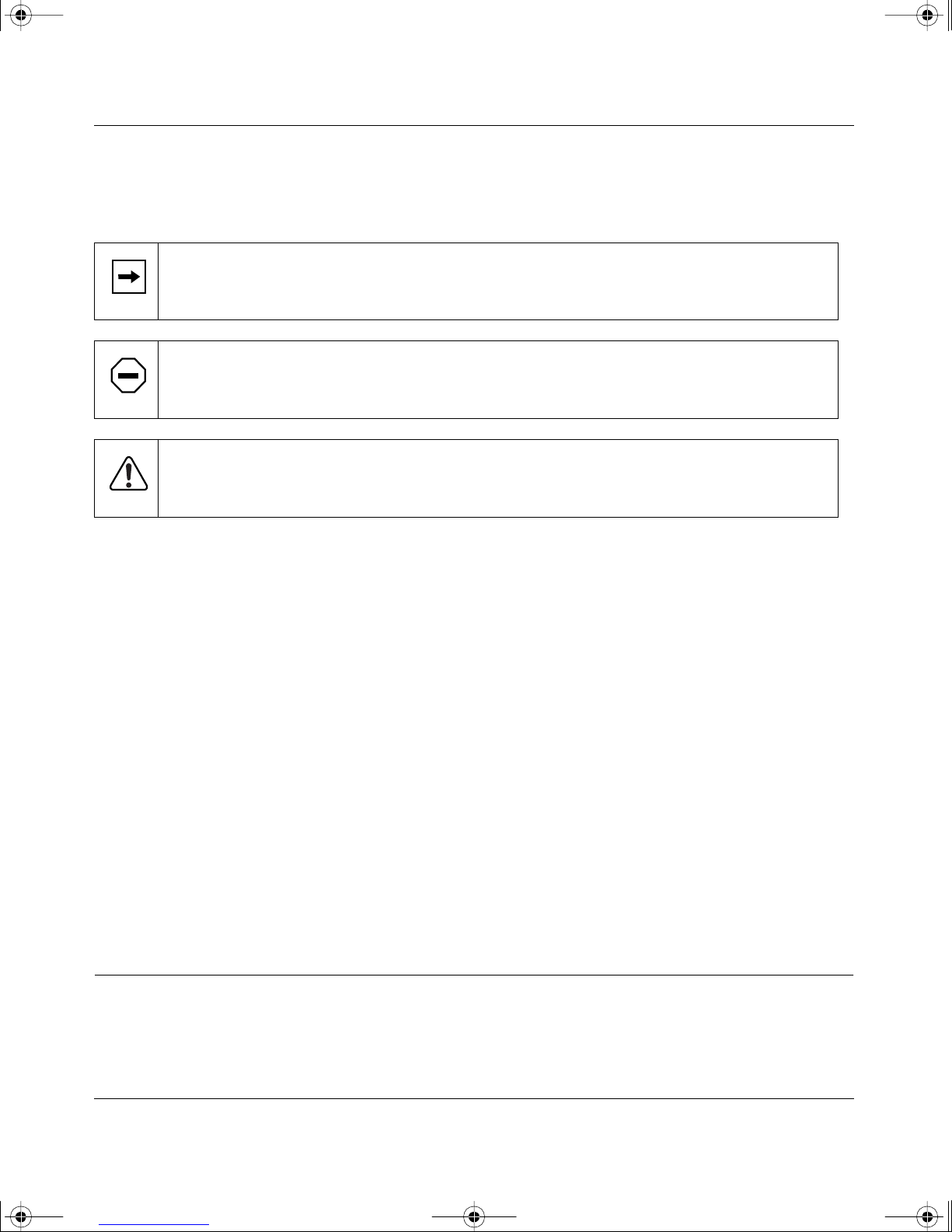
This guide uses the following formats to highlight special messa ges .
Note:
Caution:
equipment failure or loss of data.
Warning:
or equipment damage.
This format is used to highlight information of importance or special interest.
This format is used to highlight inform ation that will help you prevent
This format is used to highlight information about the possibility of injury
Use of Enter, Type, and Press
This guide uses “enter,” “type,” and “press” to describe the following actions:
• When you read “enter,” type the text and press the Enter key.
• When you read “type,” type the text, but do not press the Enter key.
• When you read “press,” press only the alphanumeric or named key.
• When you read “click,” click the left mouse button.
Other Conventions
This guide uses the following additional conventions:
italics
Initial Caps Menu titles and window and button names.
Book titles, command, and directory names.
Related Publication
For more information about the Model XM128U modem, refer to the
Model XM128 ISDN Digital Modem
version).
viii Preface
Reference Guide for the
(Bay Networks part number M-XM128NA-1 or a later
Page 9

Xm128u_bk.fm Page ix Wedn esday, Fe bruary 4, 1998 4:32 PM
Page 10

Xm128 u_bk.fm Page x Wedne sday, February 4, 1998 4:32 PM
Page 11

Xm128 u_bk.fm Page 1 Wedne sday, February 4, 1998 4:32 PM
This guide describes how to install and use the Model XM128U ISDN Digital Modem. It inc ludes
a physical description a nd installation instructions for the hardware, as we ll as instructions for
installing and using FirstGear
getting star ted. For more deta iled inf ormation about insta lling your Model XM128U modem, refer
Refere nce Guide for the Model XM128 ISDN Digital Modem.
to
™
for configuring the modem. Use this guide as a refer ence for
Chapter 1
Introduction
When use d with o ff-the-s hel f In tern et o r remo te access client software, the Mo d e l XM128U
modem enables mobile or home use rs to co nnect ov er Integrated Services Digital Networ k (ISDN)
lines to t he Interne t or t o bra nch of fi ces. The Model XM 128U modem also a ll ows a user to connec t
to the analog world through an anal og modem, a fax machine, or a telephone.
To take advantage of constant new developments while sustaining your hardware investment, the
Model XM128U modem uses flash EPROMs that enable convenient uploading of newly available
firmware.
Features
The Model XM128U modem supports a variety of compression schemes including V.42bis and
Hi/fn LZS Compression (Stac). The Model XM128U modem can effectively communicate at
speeds up to 460 kilobits per second (Kbps) over ISDN lines.
The Model XM128U modem has two analog ports to connect analog devices such as fax
machines, modems, and telephones. The Model XM128U modem can communicate o ver the two
B channels to different loc at ions simultaneously , en abl ing you to send a fax and “surf” the web at
the same time. The analog ports recognize standa rd dual-tone multifrequency (DTMF) tones as
well as pulse dialing.
Introduction 1-1
Page 12

Xm128 u_bk.fm Page 2 Wedne sday, February 4, 1998 4:32 PM
Getting Started Using FirstGear for the Model XM128U ISDN Digital Modem
The Model XM128U modem has the following speed and compatibility features:
• Plug-and-Play support for a Windows
• Full compatibility with both ISDN and remote public-switched telephone network (PSTN)
by way of ISDN
• Multiple signaling protocol compatibility with DSS1, 1TR6, NI-1, AT&T 5ESS, and Northern
Telecom DMS 100 network switches
• X.75, V.110, V.120, and Point- to-Point Protocol (PPP)
• B channel spe eds of 56 Kbps (in-band signaling) and 64 Kbps (out-of-band signaling)
• 112 Kbps/128 Kbps channel bundling: MLP and Multipoint PPP (RFC1717)
• Hi/fn LZS compr ession (Stac)
®
95 environment
• V.42bis data compression using the X.75, V.120, and bundle protocols
• Configur a bility using either FirstGe ar (a Windows 95 utility) or AT commands
• Automatic ISDN and analog call detection
• Two analog telephone jacks (analog adapters)
• Push-button switch for quick dial and teardown
• Easy-to-use F irstGear configuration software
• Flash EPROM for easy firmware upgrades
1-2 Introduction
Page 13
Xm128 u_bk.fm Page 1 Wedne sday, February 4, 1998 4:32 PM
This chapter provides information about the ha rdware features of the Model XM128U ISDN
Digital Modem. Use the key a t the bottom of each illustration to identify the panel component s.
Chapter 2
Physi cal De scrip tion
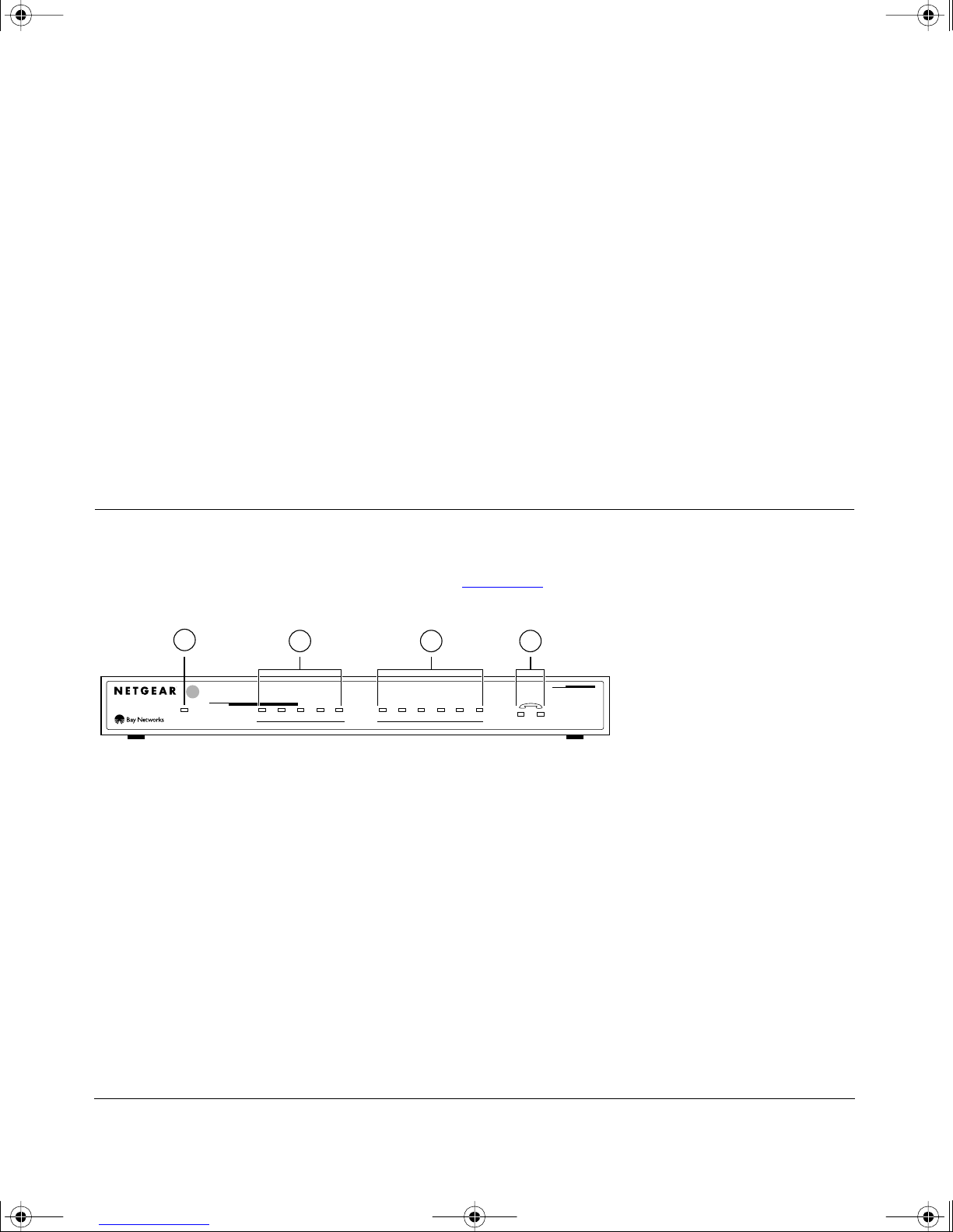
Front Panel
For easier management and control of the Model XM128U modem, familiarize yours elf with the
components on the front panel, as ill ustrated in Figure 2-1.
1
INTERFACE
U
128Kpbs
ISDN Digital Modem
Key:
1 = PWR (power) LED
2 = ISDN LEDs
3 = RS-232 COM LEDs
4 = PHONE 1 and PHONE 2 LEDs
Figure 2-1. Front panel of the Model XM128U modem (with S/T interface)
2 3 4
ISDN
DTR DSR RTS CTS TDDPWR B1 B2 AA CP
COM
RD
12
MODEL
XM128
8262EA
Physical D escription 2-1
Page 14
Xm128 u_bk.fm Page 2 Wedne sday, February 4, 1998 4:32 PM
Getting Started Using FirstGear for the Model XM128U ISDN Digital Modem
LEDs
LEDs on the front panel of the Model XM128U modem allow you to monitor and diagnose the
devi ce. Table 2-1 describes each LED.
Ta bl e 2-1 . LED desc rip tio ns
Label Color Activity Descripti on
PWR
(Power)
ISDN LEDs:
D Green On The ISDN link on the D channel is acti ve.
B1 Green On A connection is established to the B1 channel.
B2 Green On A connection is established to the B2 channel.
AA Green On The Model XM128U modem is in the auto ma tic answering m ode.
CP Green On Compression is active on either of the B channels.
RS-232
COM LEDs:
DTR Green On The data terminal or computer connected to the DTE port on
DSR Green On The Model XM128U modem is ready to communicate wi th t he
RTS Green On The data terminal or compute r connected to the DTE port on
Green On Power is supplied to the modem.
Blinking The Model XM128U modem is attempting to make a connection
to the swi tch.
Blinking An incoming call is ringing.
the Model XM128U modem is ready to communicat e.
connected data terminal or computer.
the Model XM128U modem is ready to transmit dat a.
CTS Green On The Model XM128U modem is ready to acce pt data from the
TD Green On The data terminal or computer connecte d to th e Mode l XM128U
RD Green On The data terminal or computer connected to the Model XM128U
PHONE 1 Green On The telephone connected to the port is in use.
PHONE 2 Green On The telephone connected to the port is in use.
2-2 Physical Descri ption
connected data terminal or computer.
modem is transmitting data to the modem.
modem is receiving data from the DTE port of the modem.
Page 15
Xm128 u_bk.fm Page 3 Wedne sday, February 4, 1998 4:32 PM
Getting Started Using FirstGear for the Model XM128U ISDN Digital Modem
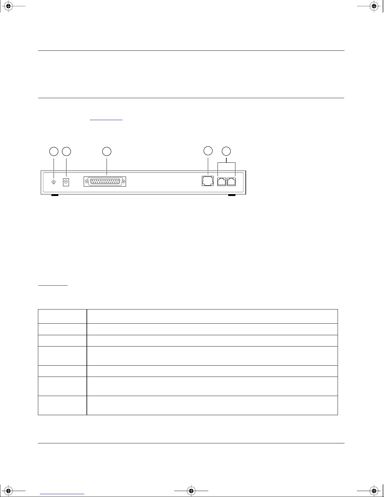
Rear Panel
As illustrated in Figure 2-2, the rear panel contains a power switch; a power receptacle; and ports
to connect a computer, ISDN line , a nd two analog devic es (telephone, fax, or modem).
1 2 3
4
5
ON/OFF
POWER
Key:
1 = ON/OFF switch
2 = Receptacle for power adapter
3 = RS-232 communica tion (COM) port for conne ct ing to a computer
4 = ISDN port for connecting to an ISDN line
5 = PHONE 1 and PHONE 2 ports for conn ecting analog devices (telephone, fax, or modem)
RS-232
ISDN
PHONE 1PHONE 2
7861MEA
Figure 2-2. Rear panel of the Model XM128U modem
Table 2-2 describes the components on the rear pan el of the Model XM128U modem.
Table 2-2. Rear panel components
Label Description
ON/OFF This switch turns power on or off.
POWER This receptacle is for the power adapter.
RS-232 This RS-232 COM port is for connecting the Model XM 128U modem to the serial port o f
a computer or data terminal.
ISDN This port is for connecting the Model XM128U modem to the ISDN line.
PHONE 1 This port is for connecting the Model XM128U modem to an analog device (telephone,
fax, or mode m) .
PHONE 2 This port is for connecting the Model XM128U modem to an analog device (telephone,
fax, or mode m) .
Physical Descri ption 2-3
Page 16

Xm128 u_bk.fm Page 4 Wedne sday, February 4, 1998 4:32 PM
Page 17

Xm128 u_bk.fm Page 1 Wedne sday, February 4, 1998 4:32 PM
This chapter provides information about installing and using the Model XM128U ISDN Digital
Modem.
Chapter 3
Installation
Package C on t ents
Your package should contain the foll owing items:
• Model XM128U ISDN Digital Modem
• Power adapter
• RJ-45 ISDN telephone cable
• Shielded RS-232 25-pin straight cable
• 25-pin to 9-pin adapter
• This manual
• Refere nce Guide for the Model XM128 ISDN Digital Modem
• CD ROM with bundled software
• 3.5-inch driver and utility diskettes
• Warranty & Owner Registration Card
Call your reseller or customer support in your area if there are a ny wrong, missing, or damaged
parts. Refer to p ag e ii of this manual for the location of custom er support in your area.
Keep the carton, includi ng the original packing materials. Use them to repack the modem if you
need to return it for repair.
To qualify for product updates and product warran ty registrations, fill in the Warranty & Owner
Registration Card within 30 days of purchase and return it to NETGEAR, I nc.
Installation 3-1
Page 18
Xm128 u_bk.fm Page 2 Wedne sday, February 4, 1998 4:32 PM
Getting Started Using FirstGear for the Model XM128U ISDN Digital Modem
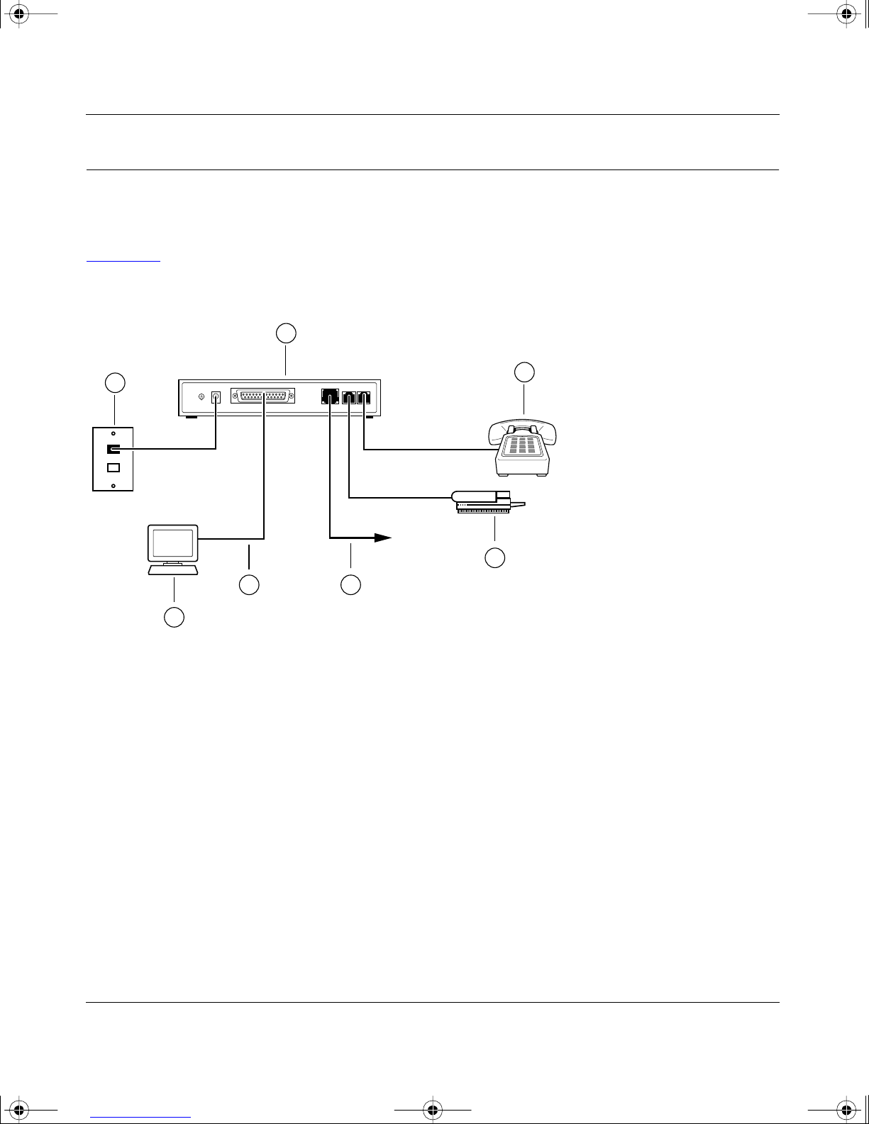
Installing the Modem
Before connecting any of the devices to your modem, make sur e the power is turned off on your
computer and your Mode l XM128U modem. Then connect th e ISDN line to your mode m. Refer to
Figure 3-1 and then to the steps follo wing the illu str ation for deta iled ins tructions f or maki ng those
connections .
1
2
4 5
3
Key:
1 = Model XM128U modem
2 = AC power adapter
3 = Computer (PC, Macintosh, or UNIX wo rkstation)
4 = Shielded RS-232 25-pin straight cable
5 = ISDN connection to wall outlet
6 = Anal og device (telephone, f ax, or modem)
Figure 3-1. Model XM128U modem connections
6
6
7860PEA
To install your Model XM128U modem:
Connect the m ale en d of the 25- pi n stra i ght ca bl e to the RS-232 COM po rt of the
1.
Model XM128U modem.
3-2 Installation
Page 19

Xm128 u_bk.fm Page 3 Wedne sday, February 4, 1998 4:32 PM
Getting Started Using FirstGear for the Model XM128U ISDN Digital Modem
Connect the other end (female end) of the 25-pin straight cable to the serial (COM) port
2.
on your computer.
Note:
If your computer has a 9-pin serial co nnector, use a 25-pin to 9-pin con verter
(25-pin male to 9-pin female). If you have a Macintosh, a special cable is needed for the
connection.
Using the special ISDN cable that is included, connect the larger end of the cable to the
3.
ISDN port on the back of t he Model XM128U modem.
Connect the smaller end of the ISDN cable to the wall outlet installed by you r telephone
4.
company.
Insert the round end of the power adapter in the POWER connector on the rear panel.
5.
Plug the power adapter in to an AC wall outlet.
6.
Turn the power on to your Model XM128U modem.
7.
Turn the power on to your computer.
8.
Verifying Hardware Installation
When the installation is complete and power a pplied to the modem, a self-test sequence begins.
The B1, B2, and AA LED lights blink on and the n of f again. After this cycl e is complete , the PWR
(power ) LED remains on.
If the test routine fails, the D LED blinks. Refer to
Digital Modem
for more information about the self-t est and the error codes.
Refere nce Guide for the Model XM128 ISDN
Installing Software for Windows
This section contains information about installing the Windows 95 and Windows NT® drivers and
about configuring Dial-Up Networking.
Installation 3-3
Page 20

Xm128 u_bk.fm Page 4 Wedne sday, February 4, 1998 4:32 PM
Getting Started Using FirstGear for the Model XM128U ISDN Digital Modem
Installing the Windows 95 Driver
The Model XM128U modem is Plug-and-Play compatible with Windows 95. If you are running
Windows 95 or Windows NT, refer to this sect ion to install the Windo ws 95 driver. If you are
running Windows 3.X, refer to Chapter 4, “Configuration,” in the
XM128 ISDN Digital Modem
to configure your modem.
To install the Windo ws 95 driver:
Turn on power to your Model XM128U modem.
1.
Turn on power to your PC, and start Windo ws 95.
2.
for information about using a ter minal program and AT commands
Refere nce Guide for the Model
The New Hardware Fo und screen opens, as illustrated in Figure 3-2
. Windo ws 95 detects your
Model XM128U modem automatically and prompts you to indicate which driver you want to
install for your new hardwa r e.
Figure 3-2. New Hardware Found screen
Click on the Driver from disk provided by hardware manufacturer field.
3.
3-4 Installation
Page 21

Xm128 u_bk.fm Page 5 Wedne sday, February 4, 1998 4:32 PM
Getting Started Using FirstGear for the Model XM128U ISDN Digital Modem
Click on OK.
4.
The Install From Disk screen opens, as illustr ated in Figure 3-3
Figure 3-3. Install From Disk screen
Insert the NETGEAR XM128 Driver Disk in the floppy driv e.
5.
As instructed on the Install From Disk screen, type A:\ to find the driver disk.
6.
Click on OK.
7.
The Select Device sc reen opens, as illustrated in Figure 3-4
.
.
Figure 3-4. Select Device screen
Installation 3-5
Page 22

Xm128 u_bk.fm Page 6 Wedne sday, February 4, 1998 4:32 PM
Getting Started Using FirstGear for the Model XM128U ISDN Digital Modem
Select the desired modem driver .
8.
In most cases, depending on whether your ISP supports 64K or 128K connection, you will
want to select one of the following:
Netgear XM128, PPP 64K
or
Netgear XM128, MP-PPP 128K
Click on OK.
9.
Click on OK again.
10.
The installa tion of your XM128 modem driver is comple te. You can now use programs such
as Dial-Up Networking.
Installing and Launching FirstGear
If you are not setting up your Model XM128U modem with a computer running Windows 95, you
must have a termina l program that allows you to send and receive AT commands and responses
from the modem. For further information about manual configuration, refer to Chapter 4,
“Confi gur ation,” in
To configure your M odel XM128U mo dem with a comput er runni ng W indo ws 95, you must inst all
the NETGEAR FirstGear software that is included on a disk in your package contents.
Reference Guide for the Model XM128 ISDN Digital Modem
.
3-6 Installation
Page 23

Xm128 u_bk.fm Page 7 Wedne sday, February 4, 1998 4:32 PM
Getting Started Using FirstGear for the Model XM128U ISDN Digital Modem
To install the FirstGear software:
Insert your NETGEAR FirstGear disk into Drive A on your computer.
1.
Select Run.... from the Start menu of Windows 95.
2.
Type A:\Setup.exe and press [Enter].
3.
The Welcome screen, as illustrated in Figure 3-5
, opens.
Figure 3-5. Welcome screen
Follow the instructions on your screen until the installation is complete.
4.
The FirstGear software installation is complete. You can now run the Firs tGear software.
Installation 3-7
Page 24

Xm128 u_bk.fm Page 8 Wedne sday, February 4, 1998 4:32 PM
Getting Started Using FirstGear for the Model XM128U ISDN Digital Modem
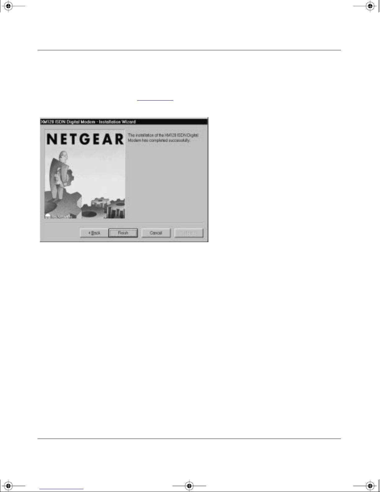
In the final scr een, check the box to launch the applicat ion that will automati cally launch
5.
the FirstGear Wizard. Figure 3-6 illustrates the Setup Complete screen.
Figure 3-6. S e tup C o m pl e te s cree n
FirstGear Installation Wizard
The FirstGear Installation Wizard provide s step-by-step instructions to set up your ISDN Digital
Modem because installing an ISDN modem can be somewhat confusing. You must enter the
telephone numbers assigned to the ISDN line and a Service Profile I D (SPID) as well as select the
appropriate switc h type. T o further complicate matters, the number of phone numbers, the SPIDs,
and the actual switch type may vary based on your location within North America. In order to
simplify the installation proce ss, your NETGEAR Model XM128U ISDN Digital Modem comes
with an Installation Wizard. By simply ent ering the assigned telephone number(s), you enable the
Wiz ard to a utomatically determine the corresponding SPIDs and chosen switch type .
3-8 Installation
Page 25

Xm128 u_bk.fm Page 9 Wedne sday, February 4, 1998 4:32 PM
Getting Started Using FirstGear for the Model XM128U ISDN Digital Modem
You have a choice betwe en launching this application automatically during the installation of
FirstGear or running it later fr om the NETGEAR program group folder. Before you can run the
Wiz ard, you must perform the following steps:
You must first have an active ISDN line (provided by your local telephone company).
1.
You must connect the Model XM128U modem to y our PC and the ISDN line as d escribe d
2.
on page 3-2 in “Installing the Modem.”
Make sure that power has been applied to the modem and the PWR LED is on.
3.
Install the Windows 95/NT drivers as described on page 3-4.
4.
If you opte d not to launch the Wizard automatic ally during FirstGear installation, do so now by
double-clicking on the appropriat e icon from the NETGEAR program group folder.
The introducti on scre en opens as shown in Figure 3-7
Figure 3-7. Introduction screen
.
Installation 3-9
Page 26

Xm128 u_bk.fm Page 10 Wed ne sday, February 4, 1998 4:32 PM
Getting Started Using FirstGear for the Model XM128U ISDN Digital Modem
To launch FirstGear from the NETGEAR program folder:
Click on Next to continue, and the Telephone numbers assigned screen appears as shown
1.
in Figure 3-8 .
Figure 3-8. Telephone numbers assigned screen
Refer to the information supplied by your local telephone company. If you have been
2.
assigned only one telephone number, select 1. Otherwise, select 2.
3-10 Installation
Page 27

Xm128 u_bk.fm Page 11 Wed ne sday, February 4, 1998 4:32 PM
Getting Started Using FirstGear for the Model XM128U ISDN Digital Modem
Click on Next.
3.
Based on the selection on the previous screen, you will be able to enter either one or two
telephone numbers. Enter eac h telephone number, including the area code, in the Telephone
number entry screen illustrated in Figure 3-9
.
Figure 3-9. Telephone number entry screen
Installation 3-11
Page 28
Xm128 u_bk.fm Page 12 Wed ne sday, February 4, 1998 4:32 PM
Getting Started Using FirstGear for the Model XM128U ISDN Digital Modem
After you enter the telephone number(s), click on Next to continue.
4.
At this point, the FirstGe ar Wizard will automatically detect the Servic e Profile IDs (SPIDs)
and the appropriate switch type. When the procedure is successful, the Wizard displays the
final sta tus screen sho wn in Figure 3-10
.
Figure 3-10. Final status screen
Click on Finish to exit FirstGear Installation Wizard.
5.
3-12 Installation
Page 29

Xm128 u_bk.fm Page 13 Wed ne sday, February 4, 1998 4:32 PM
Getting Started Using FirstGear for the Model XM128U ISDN Digital Modem
If the Wizard is unable to determine the SPID and/or switch values, you will be prompted to enter
these values directly. Refer to the information supplied by your loca l telephone company. The
ISDN Settings menu tab, as illus trated in Figure 3-11, is used to enter the SPID and switc h values
directly.
Figure 3-11. ISDN Settings menu tab screen
To enter the SPID and switch values directly:
Enter eac h of the val ues into the corres po n di ng fields . Th e tel ep ho ne numbers have
1.
already been entered based on values entered earlier.
Enter the corresponding SPID numbers and select the switc h type from the pu ll-down
2.
menu.
Click on OK to continue.
3.
Based on these new values, the Wizard attempts a test call. If the call fails, you will be prompted
once again to recheck the values. If the problem persi sts, contact NETGEAR custom er suppor t.
Installation 3-13
Page 30

Xm128 u_bk.fm Page 14 Wed ne sday, February 4, 1998 4:32 PM
Getting Started Using FirstGear for the Model XM128U ISDN Digital Modem
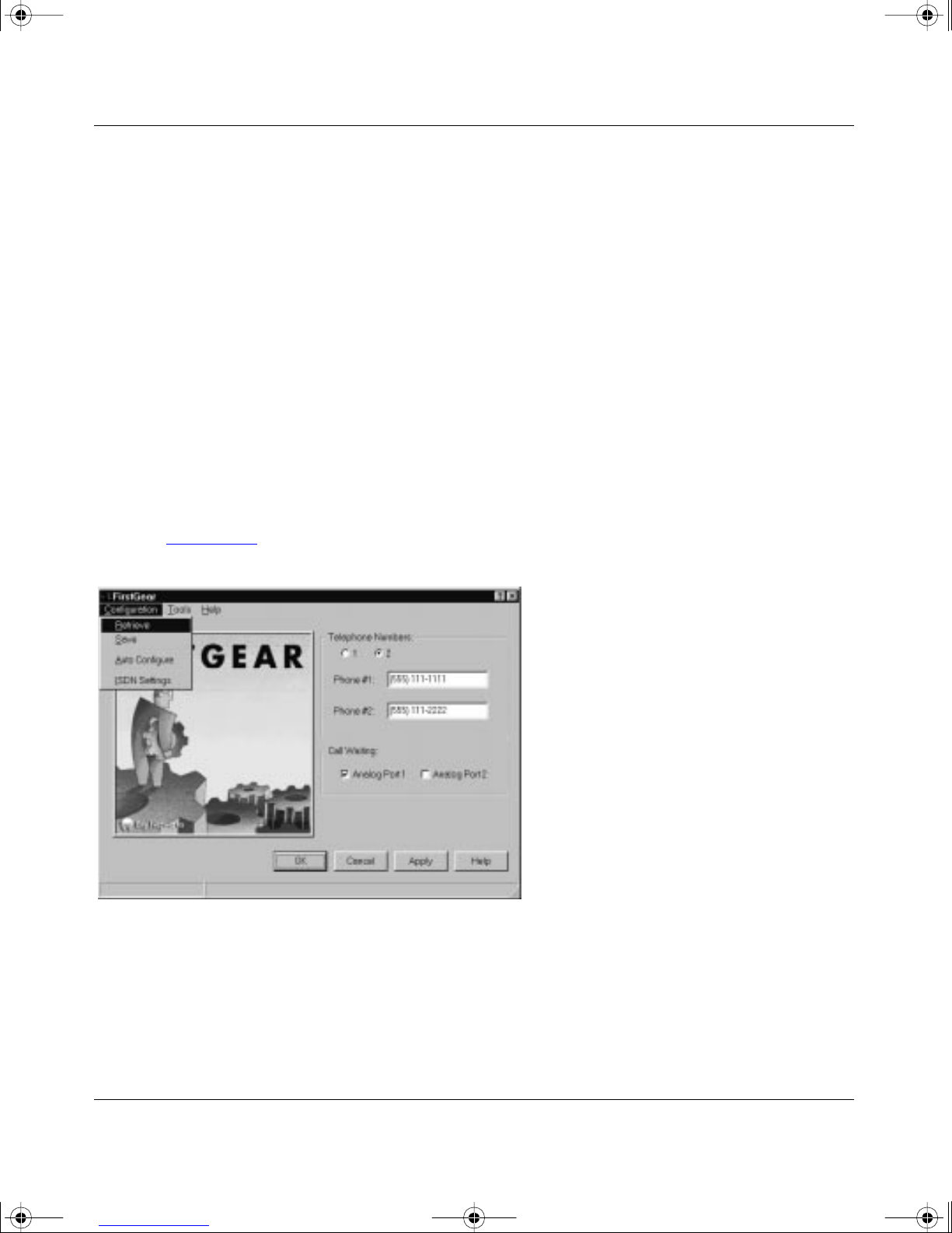
About FirstGear
FirstGear allows you to set the telephone numbers, run diagnostics, and enable/disable the Call
Waiting feature. When you run Fi rstGear, it automatically displ ays the curre nt setti ng of the Model
XM128U modem. Figure 3-12 shows the Configuration menu screen.
Figure 3-12. Configuration menu screen
The Telephone Numbers field displays the current phone number settings. Based on the
information given to you by your local telephone company, you will have either one or two
telephone numbers assigned to your ISDN line. The appropriate radio button at the top of the
field will indicate whether you have one or two telephone numbers assigned.
If you need to change the telephone numbers, type them into the appropriate fields (Phone #1
or Phone #2, incl uding area codes). When savi ng the configuration (by clicking on OK or Apply),
FirstGear automatically detects the Se rvice Profile IDs (SPIDs) and switch type assigned to
your ISDN line.
To enable Call Wa iting on each analog phone port, check the appropriate box (Analog Port 1 and/
or Analog Port 2). To disable Call Waiting on a port, clear the box for that port.
3-14 Installation
Page 31
Xm128 u_bk.fm Page 15 Wed ne sday, February 4, 1998 4:32 PM
Getting Started Using FirstGear for the Model XM128U ISDN Digital Modem
Clicking on the buttons at the bottom of the screen will have the following results:
• OK
The OK button saves the current configuration and exits the progr am.
• Cancel
The Cancel button exits the program without saving the current configuration.
• Apply
The Apply butto n sa ves the current configuration but does not exit FirstGear.
• Help
The Help button displays the online help.
There are also three pull-down menus: Configuration, Tools, and Help.
The Configura tion menu supports four se lections: Retrieve, Save, Auto Configure , and ISDN
Settings. Figur e 3-13
shows the Configuration menu choices.
Figure 3-13. Retrieve menu tab screen
Installation 3-15
Page 32

Xm128 u_bk.fm Page 16 Wed ne sday, February 4, 1998 4:32 PM
Getting Started Using FirstGear for the Model XM128U ISDN Digital Modem
The Configuration menu selections have the following results:
• Retrieve
Selecting Retrieve allows you to review the current setting of the Model XM128U modem.
• Save
Selecting Save allows you to update the modem with the new settings.
• Auto Configure
Selecting Aut o Conf igur e c auses the modem t o autom atical ly dete ct t he SPI Ds and switch type
based on the current telephone numbers.
• ISDN Settings
Selecting ISDN Settings displays the current ISDN settings including the telephone numbers,
SPIDs, and switch type.
Figure 3-14
shows the ISDN Settings menu bar.
Figure 3-14. ISDN Settings menu tab screen
3-16 Installation
Page 33

Xm128 u_bk.fm Page 17 Wed ne sday, February 4, 1998 4:32 PM
Getting Started Using FirstGear for the Model XM128U ISDN Digital Modem
The Tools menu provides you with the ability to program some of the advanced feat ures using
AT commands as well as a diagnostic tool.
Figure 3-15
Figure 3-15. Tools menu screen
shows the Tools menu choices displayed.
By selecting the AT Commands menu bar, you can enter AT commands directly to set some of
the advanced features of the Model XM128U modem (refer to the
Refere nce Guide for the Model
XM128 ISDN Digital Modem).
The Diagnostics Menu provides the following two selections:
• Self Test
Self Test checks the Model XM128U modem hardware integrity.
• Test Call
T est Call checks the inte grity of the ISDN connec tion by pla cing a call f rom the f irst teleph one
number to the second telephone number. Be aware that you ma y be charged for this call by
your local telephone company.
Installation 3-17
Page 34

Xm128 u_bk.fm Page 18 Wed ne sday, February 4, 1998 4:32 PM
Getting Started Using FirstGear for the Model XM128U ISDN Digital Modem
The Help menu allows you to retri eve an online version of this manual. Figure 3-16 shows the
Help menu bar selected.
Figure 3-16. Help menu screen
Configuring Windo ws 95 Dial-Up Networking
You must install Windows 95 and Dial-Up Networking before proceeding with this section.
Configuring Dial-Up Networking for One B Channel
To configure your Model XM128U modem with Dial-Up Networking for one B channel:
Double-click on the My Computer icon.
1.
Double-click on the Dial-Up Networking folder.
2.
3-18 Installation
Page 35

Xm128 u_bk.fm Page 19 Wed ne sday, February 4, 1998 4:32 PM
Getting Started Using FirstGear for the Model XM128U ISDN Digital Modem
Double-click on the Make New Connection icon fr om within the Dial-Up Networking
3.
folder.
The Make New Connection screen, as illustrated in Figure 3-17
Figure 3-17. Make New Connection screen
Type a name f or your connection in the Type a name for the computer you ar e dialing
4.
, open s.
field.
Select the appropriate Model XM128U modem driver for the dial-up connect ion.
5.
Each dial-up connection can use a different Model XM128U modem driver. Each driver
automatically selects the appropriate protocol and data rate. For example, you may want
to use the Netgear XM128, Internet PPP 64K drive r for your 64K connection to your remote
LAN while you are telecom muting. On the other hand, you can set up a second dial-up
connection with the Netgear XM128, Internet PPP 128K driver for your 128K Internet
connection through your local ISP. Each dial-u p connection uses a different driv e r.
Installation 3-19
Page 36

Xm128 u_bk.fm Page 20 Wed ne sday, February 4, 1998 4:32 PM
Getting Started Using FirstGear for the Model XM128U ISDN Digital Modem
Click on Next.
6.
The second Make New Connection screen opens, as illustrat ed in Figure 3-18
Figure 3-18. Make New Connection screen for entering ISP information
Type the phone number of the Internet service provider (ISP) or host you will be calling.
7.
.
Click on Next.
8.
Click on Finish.
9.
A new icon is created in the Dial-Up Networking folder.
If your ISP requires you to enter DNS and WINS addresses, perform steps 10 through 18.
Otherwise, proce ed to step 19.
3-20 Installation
Page 37

Xm128 u_bk.fm Page 21 Wed ne sday, February 4, 1998 4:32 PM
Getting Started Using FirstGear for the Model XM128U ISDN Digital Modem
Select the new icon in the Dial-Up Networking folder, and click on the right mouse
10.
button.
Select Prope rties from th e me nu .
11.
The My Connection screen, as illu strated in Figure 3-19
, opens.
Figure 3-19. My Connection screen
Make sure that your Model XM128U modem appears in the Connect using box.
12.
If you have settings given to you by your ISP, follow those guidelines and go to step 20 on
page 3-23
If you do
Installation 3-21
.
not
hav e guidelines given to you by your ISP, go to step 13.
Page 38

Xm128 u_bk.fm Page 22 Wed ne sday, February 4, 1998 4:32 PM
Getting Started Using FirstGear for the Model XM128U ISDN Digital Modem
Click on the Server Types tab.
13.
The Server Types tab opens, as illustrate d in Figure 3-20
If you are using PPP, use the default settings shown in Figure 3-20
.
.
If you are connecting to a LAN, select Log on to network.
®
If you are logging on to a Microsoft
Windows networ k, select NetBEUI .
If you are logging on to a Novell network, select IPX/SPX Compatible.
If you are logging on to an Internet connection, select TCP/IP.
Figure 3-20. Server Types tab screen
3-22 Installation
Page 39

Xm128 u_bk.fm Page 23 Wed ne sday, February 4, 1998 4:32 PM
Getting Started Using FirstGear for the Model XM128U ISDN Digital Modem
Click on TCP/IP Settings.
14.
The TCP/IP Settings screen, a s illustrated in Figure 3-21
, opens.
Figure 3-21. TCP/IP Settings screen
Click on the Specify name server addresses radio button.
15.
Enter your primary and secondary Domain Name Server (DNS) num b ers .
16.
Obtain DNS number s from your ISP. If your host requires you to specify an IP address,
go to the next step. If your host does not require you to specify an IP address, go to step 18.
Click on Specify an IP address and enter y our IP address on ly.
17.
Click on OK
18.
.
This step completes the remote connection definition.
Locate the icon of the connection profile you created in your Dial-Up Networking folder
19.
and double-click on it.
Type the user name and password for your ISP if they are incorrect or missin g.
20.
Click on the Connect button.
21.
Your Model XM128U modem dials the number and establishes a connection.
This step completes the conf iguration of Dial-Up Networking for Windows 95.
Installation 3-23
Page 40

Xm128 u_bk.fm Page 24 Wed ne sday, February 4, 1998 4:32 PM
Getting Started Using FirstGear for the Model XM128U ISDN Digital Modem
Configuring Dial-Up Networking for Two B Channels
To configure your Model XM128U modem for use with two B channels using Multilink PPP:
Double-click on the My Computer icon.
1.
Double-click on the Dial-Up Networking folder.
2.
Double-click on the Make New Connection icon fr om within the Dial-Up Networking
3.
folder.
Choose a name for your connection and select XM128 from the drop-down menu.
4.
Select Netgear XM128, Internet PPP 128K.
5.
Click on Next.
6.
The Make New Connection screen, as illustrated in Figure 3-18
Type the phone number(s) of the ISP or host you will be calling.
7.
on page 3-20, opens.
Some ISPs require only one phone number to make multiple-link connection. If your ISP
requires you to dial a diff erent number (one for each B channel), separate the two numbers
with a plus si gn (+). Ot herwise, enter t he number as normal ( for e xample: 5551 111+55522 22).
Click on Next.
8.
Click on Finish.
9.
A new icon is created in the Dial-Up Networking folder.
Click your right mouse button on the new icon.
10.
Select Prope rties from th e po p-u p m en u.
11.
The My Connection screen, as illu strated in Figure 3-19
on page 3-21, opens.
Make sure the Use country code and area code field is not checked off. If this field is checked,
Windows 95 removes the plus sign (+) from the phone number when you close the window,
which causes failed connections in the future.
Make sure your Netgear XM128, Inter ne t PPP 128K appears in the Connect using box. If
settings have been given to you by your ISP, follow those guidelines and go to step 20 on
page 3-23
.
If settings have
not
been given to you by your ISP, go to step 13 on page 3-22
Either choice completes the configuration of Dial-Up Networking for Windows 95 using two
B channels.
3-24 Installation
.
Page 41

Xm128 u_bk.fm Page 1 Wedne sday, February 4, 1998 4:32 PM
B
Index
bulleti n board serv ic e ii
C
Configuration menu screen 3-14
conventions
customer support
vii
ii
F
features 1-1
FirstGear softwa r e, in s talling
front panel
2-1
3-6
H
Help menu screen 3-18
I
Instal l From Disk screen 3-4, 3-5
3-2
2-3
3-9
installation
Introd uction screen
ISDN port
ISDN Settings menu tab screen
L
3-13
M
Make Ne w Connection screen 3-19, 3-20
My Connection screen
3-21
N
New Hardwa re Found screen 3-4
NT driver, installing
3-3
O
ON/OFF switch 2-3
P
pack ag e co ntents 3-1
2-3
2-3
2-3
PHONE 1 port
PHONE 2 port
2-3
ports
power receptacle
R
rear panel 2-3
related publicaton
Retrieve menu tab screen
x
3-15
Launch screen 3-8
LED descriptions
Index 1
2-2, 3-3
Page 42

Xm128 u_bk.fm Page 2 Wedne sday, February 4, 1998 4:32 PM
S
screens
3-9
3-5
3-16
3-21
3-23
3-14
3-4, 3-5
3-15
3-22
3-5
3-22
Configuration menu
Finish In stallatio n Wizar d
2-3
3-8
2-3
3-7
3-18
3-17
Help Menu
Install From Disk
Introduction
ISDN menu tab
ISDN Settings menu tab
ISDN Settings menu tab screen
Launch
Make New Connection
My Connection
New Hardwa re Found
Retrieve menu tab
Select Device
Server Types tab
TCP/ I P Settings
Telephone number entry
Telephone numbers assigned
Tools menu
Welcome
Select Device screen
seria l port
Server Types tab screen
switch
3-12
3-13
3-19, 3-20
3-4
3-11
3-10
3-16
T
TCP/ IP Settings scre en 3-23
Telephone number entry screen
Telephone numbers assigned screen
Tools menu screen
3-17
3-11
3-10
U
Use viii
W
Welcome screen 3-7
Windows 95
confi guring Di al-Up Net worki ng for one B cha nnel
3-18
configuring Dial-U p N etworking for two B
channels
driver, installing
World Wide We b
3-24
3-4
ii
2 Index
 Loading...