

Page 1
ReadyNAS 4200
Hardware Manual
350 East Plumeria Drive
San Jose, CA 95134
USA
May 2010
202-10628-01
v1.0
Page 2

ReadyNAS 4200 Hardware Manual
© 2010 NETGEAR, Inc. All rights reserved.
No part of this publication may be reproduced, transmitted, transcribed, stored in a retrieval system, or translated
into any language in any form or by any means without the written permission of NETGEAR, Inc.
Tech nica l Sup port
When you register your product at http://www.netgear.com/register, we can provide you with faster expert technical
support and timely notices of product and software upgrades.
NETGEAR, Inc.
350 East Plumeria Drive
San Jose, CA 95134 USA
E-mail: support@netgear.com
Website: http://www.netgear.com
Phone: 1-888-NETGEAR, for US & Canada only. For other countries, see your Support information card.
Trademarks
NETGEAR, the NETGEAR logo, ProSafe, Smart Wizard, and Auto Uplink are trademarks or registered
trademarks of NETGEAR, Inc. Microsoft, Windows, Windows NT, and Vista are registered trademarks of Microsoft
Corporation. Other brand and product names are registered trademarks or trademarks of their respective holders.
Statement of Conditions
To improve internal design, operational function, and/or reliability, NETGEAR reserves the right to make changes
to the products described in this document without notice. NETGEAR does not assume any liability that may occur
due to the use or application of the product(s) or circuit layout(s) described herein.
Revision History
Publication Part Number Version Publish Date
202-10628-01 v1.0 May 2010
2 |
Page 3

Table of Contents
Chapter 1 Getting Started
Control Panel, Status Displays, Ports, and Drive Bays . . . . . . . . . . . . . . . . 6
Front Panel . . . . . . . . . . . . . . . . . . . . . . . . . . . . . . . . . . . . . . . . . . . . . . . 6
Disk Tray, Release, and Tray Handle . . . . . . . . . . . . . . . . . . . . . . . . . . . 6
Rear Panel. . . . . . . . . . . . . . . . . . . . . . . . . . . . . . . . . . . . . . . . . . . . . . . . 7
Rack Mount Setup . . . . . . . . . . . . . . . . . . . . . . . . . . . . . . . . . . . . . . . . . . . . 8
Choosing a Setup Location . . . . . . . . . . . . . . . . . . . . . . . . . . . . . . . . . . . . . 9
Preparing for Setup . . . . . . . . . . . . . . . . . . . . . . . . . . . . . . . . . . . . . . . . . 9
Installing the System into a Rack. . . . . . . . . . . . . . . . . . . . . . . . . . . . . . . 9
Initial Setup, IP Address, and Login Password . . . . . . . . . . . . . . . . . . . . . 11
Defaults . . . . . . . . . . . . . . . . . . . . . . . . . . . . . . . . . . . . . . . . . . . . . . . . . 11
Safety Warning . . . . . . . . . . . . . . . . . . . . . . . . . . . . . . . . . . . . . . . . . . . . . 12
Electrical Safety Precautions . . . . . . . . . . . . . . . . . . . . . . . . . . . . . . . . . 12
General Safety Precautions. . . . . . . . . . . . . . . . . . . . . . . . . . . . . . . . . . 13
Electrostatic Discharge (ESD) Precautions . . . . . . . . . . . . . . . . . . . . . . 14
Rack Mount Precautions . . . . . . . . . . . . . . . . . . . . . . . . . . . . . . . . . . . . 14
Chapter 2 Diagnostics and Maintenance
Control Panel Diagnostic and Status Information . . . . . . . . . . . . . . . . . . . 16
Performing System Shutdown . . . . . . . . . . . . . . . . . . . . . . . . . . . . . . . . . . 18
Using the Power Button . . . . . . . . . . . . . . . . . . . . . . . . . . . . . . . . . . . . . 18
Using the FrontView Browser User Interface. . . . . . . . . . . . . . . . . . . . . 18
Understanding the System Diagnostics Boot Menu . . . . . . . . . . . . . . . . . 19
Reinstall Firmware using OS Reinstall Option. . . . . . . . . . . . . . . . . . . . . . 21
Using the Boot Menu to Format a RAID Volume. . . . . . . . . . . . . . . . . . . . 22
Adding or Replacing Disks . . . . . . . . . . . . . . . . . . . . . . . . . . . . . . . . . . . . 25
Adding a New Disk . . . . . . . . . . . . . . . . . . . . . . . . . . . . . . . . . . . . . . . . 25
Failed Disk Notification . . . . . . . . . . . . . . . . . . . . . . . . . . . . . . . . . . . . . 26
Choosing a Replacement Disk . . . . . . . . . . . . . . . . . . . . . . . . . . . . . . . 26
Replacing a Failed Disk . . . . . . . . . . . . . . . . . . . . . . . . . . . . . . . . . . . . . 27
Replacing System Components . . . . . . . . . . . . . . . . . . . . . . . . . . . . . . . . 28
Replacing a System Fan . . . . . . . . . . . . . . . . . . . . . . . . . . . . . . . . . . . . 29
Replacing a Power Supply. . . . . . . . . . . . . . . . . . . . . . . . . . . . . . . . . . . 30
Replacing the Onboard Battery . . . . . . . . . . . . . . . . . . . . . . . . . . . . . . . 30
Table of Contents | 3
Page 4

ReadyNAS 4200 Hardware Manual
Appendix A Default Settings and Specifications
Factory Default Settings . . . . . . . . . . . . . . . . . . . . . . . . . . . . . . . . . . . . . . .32
Technical Specifications . . . . . . . . . . . . . . . . . . . . . . . . . . . . . . . . . . . . . . .33
Appendix B Notification of Compliance
Index
4 | T able of Contents
Page 5

1
1
Getting Started
ReadyNAS 4200
This chapter provides an overview of the unit’s physical features.
Topics discussed in this chapter include:
• Control Panel, Status Displays, Ports, and Drive Bays
• Rack Mount Setup
• Choosing a Setup Location
• Initial Setup, IP Address, and Login Password
• Safety Warning
Chapter 1: Getting Started | 5
Page 6
ReadyNAS 4200 Hardware Manual
WARNING!
1
2
3
Disk tray release
push switch
Disk tray
handle
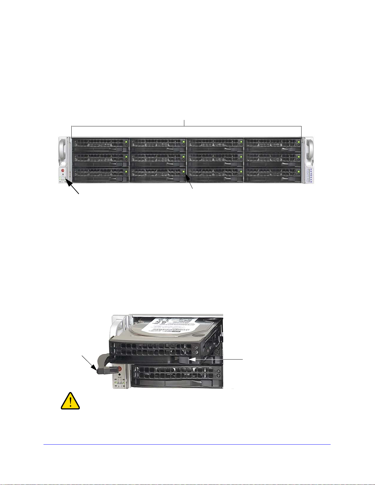
Control Panel, Status Displays, Ports, and Drive Bays
This section introduces the ReadyNAS control panel, status display, ports, and disk bays.
Front Panel
1. Twelve disk bays with hot-pluggable disk trays that each include two status lights.
2. Control panel with status lights
• Power and Reset buttons
• Power, LAN, disk, and fan status lights
3. Status lights
• Green: Disk present and activity light
• Amber or off: Disk failure light
Disk Tray, Release, and Tray Handle
The disk tray features a push switch-activated pop-out tray handle.
Regardless of how many hard drives are installed, all drive trays
must remain in the drive bays to maintain proper airflow.
6 | Chapter 1: Getting Started
Page 7
ReadyNAS 4200 Hardware Manual
34 65
1
2
7
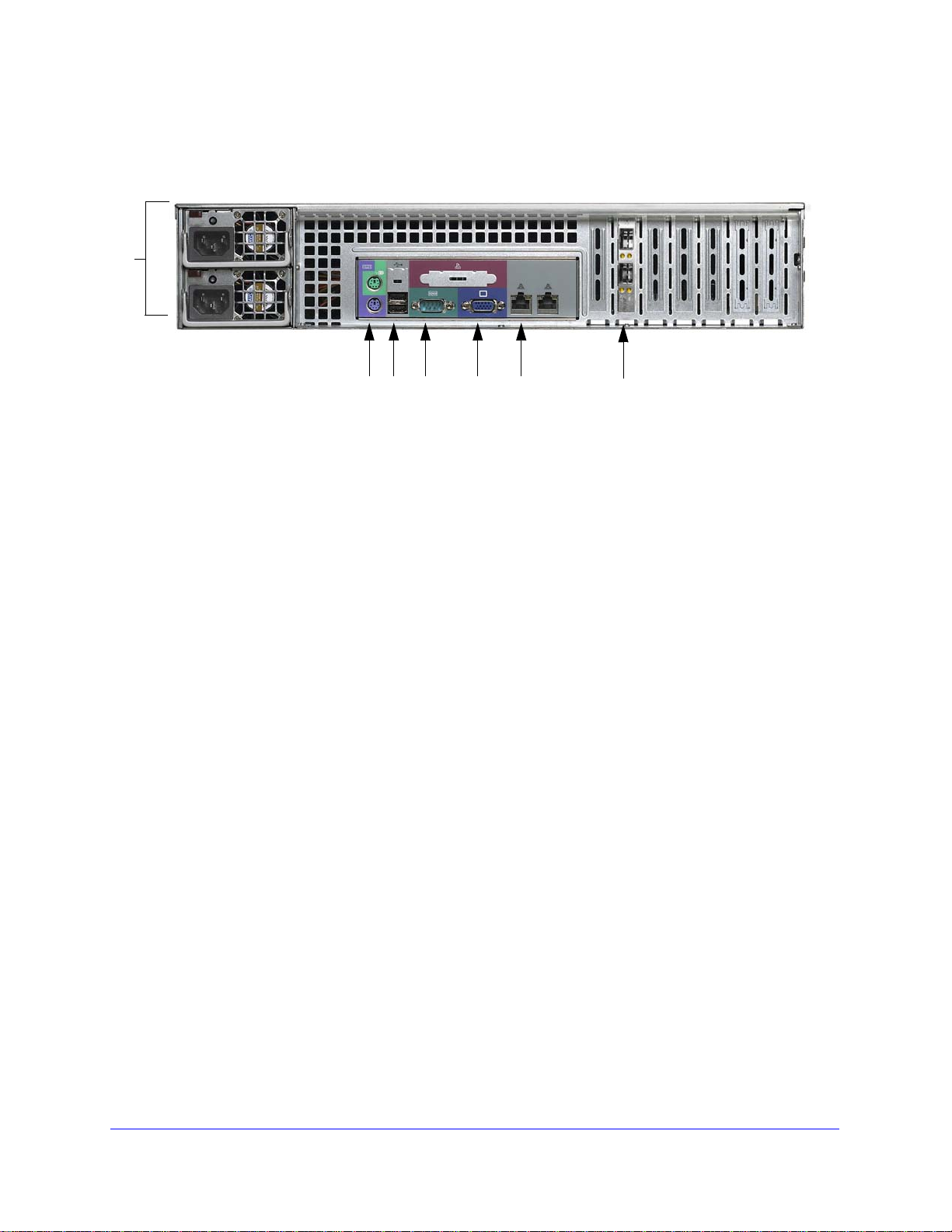
Rear Panel
1. Dual power supplies
2. PS2 keyboard and mouse ports
3. Two USB ports
4. RS232 console port
5. VGA monitor port
6. Two Gigabit Ethernet ports with failover and link aggregation
7. Two 10 G Ethernet ports
Chapter 1: Get ting Started | 7
Page 8

ReadyNAS 4200 Hardware Manual
DANGER:
Rack Mount Setup
Use the included rack mount hardware to install the unit according to the following
instructions.
A unit with installed drives can weigh more than 80 pounds. So as to
avoid injury or damage to the equipment, plan to perform the rack
mount installation with appropriate assistance.
Ambient Operating Temperature
If the unit installed in a closed or multi-unit rack assembly, the ambient operating temperature
of the rack environment might be greater than the ambient temperature of the room.
Therefore, consideration should be given to installing the equipment in an environment
compatible with the maximum rated ambient temperature found in
Specifications " in Appendix A.
"Default Settings and
Reduced Airflow
Equipment should be mounted into a rack so that the amount of airflow required for safe
operation is not compromised.
Mechanical Loading
Equipment should be mounted into a rack so that a hazardous condition does not arise due
to uneven mechanical loading.
Circuit Overloading
Consideration should be given to the connection of the equipment to the power supply
circuitry and the effect that any possible overloading of circuits might have on over current
protection and power supply wiring. Consider equipment nameplate ratings when addressing
this concern.
Reliable Ground
A reliable ground must be maintained at all times. To ensure this, the rack itself should be
grounded. Particular attention should be given to power supply connections other than the
direct connections to the branch circuit (for example, the use of power strips).
8 | Chapter 1: Getting Started
Page 9
ReadyNAS 4200 Hardware Manual
Choosing a Setup Location
Note: This product is intended for installation in a restricted access
location (dedicated equipment rooms, service closets, and the like)
only.
Leave enough clearance in front of the rack to enable you to open the front door completely
(about 25 inches) and approximately 30 inches of clearance in the back of the rack to allow
for sufficient airflow and ease in servicing.
Preparing for Setup
Read these instructions in their entirety before you begin. Locate the ReadyNAS 4200
shipping carton, remove the rack mounting kit and prepare to work with it.
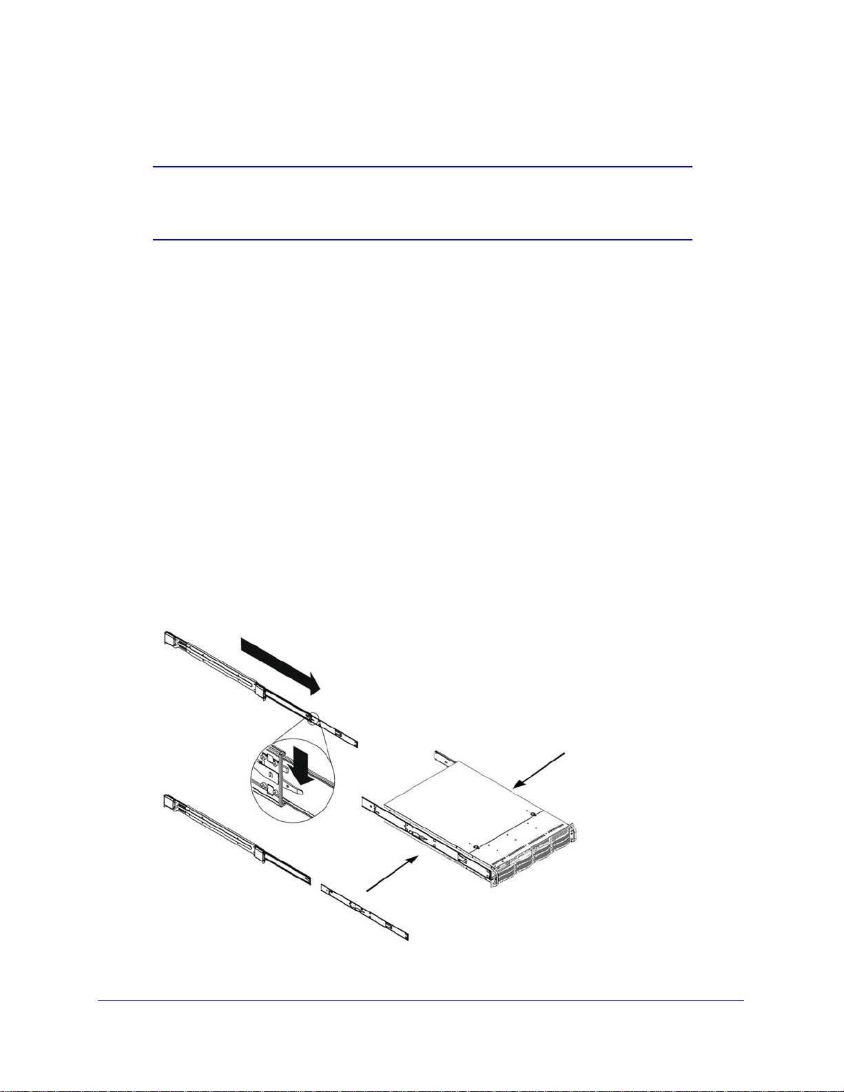
Installing the System into a Rack
To install the system into a rack:
1. The rack mounting kit contains two rail assemblies. Each assembly consists of two
sections: an inner fixed chassis rail that secures directly to the ReadyNAS 4200 chassis
and an outer fixed rack rail that secures directly to the rack itself. Extend the rail
assembly by pulling it outward. Press the release tab and separate the inner rail from
the outer assembly.
Chapter 1: Get ting Started | 9
Page 10
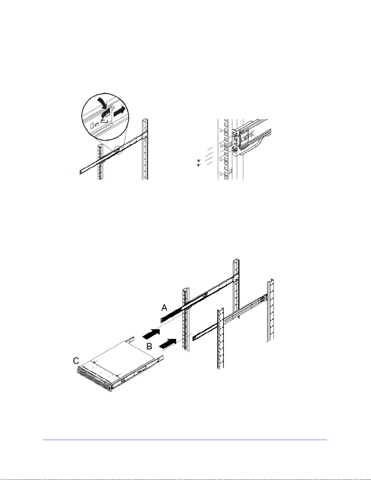
ReadyNAS 4200 Hardware Manual
2. Use the provided mounting screws to mount the inner rails to the system chassis.
3. Fasten the backs of the outer rails to the rack with screws. Press the release to extend the
rails. Hang the hooks of the rails into the rack holes, and fasten the rails to the rack.
4. Attach chassis to the rack.
a. Extend the ball shuttle (A) to the very front.
b. Align the rails (B) and push the chassis in.
c. Secure the handles to the outer rails (C) with screws.
The rack mount installation is complete.
10 | Chapter 1: Getting Started
Page 11

ReadyNAS 4200 Hardware Manual
Initial Setup, IP Address, and Login Password
Follow the instructions in the NETGEAR ReadyNAS Installation Guide that came with your
unit to install it. An electronic copy of the installation guide is on the product CD, on the
NETGEAR website, and on http://readynas.com/documentation.
Defaults
Estimated setup time is about 20 minutes.
• Default IP configuration: set to DHCP; if the unit does not get an IP address, it defaults to
192.168.168.168.
• Default administrator user name: admin
• Default password: netgear1
Both the user name and password are case-sensitive.
For information about using ReadyNAS 4200 RAIDar and FrontView software to log in,
configure, and manage your system, see the ReadyNAS for Business Software Manual.
Chapter 1: Getting Started | 11
Page 12
ReadyNAS 4200 Hardware Manual
DANGER:
Safety Warning
1. The equipment contains no operator access areas and is certified for installation only by
trained personnel, according to the installation instructions provided with each unit.
2. The socket-outlet shall be installed near the equipment and shall be easily accessible.
3. Observe the onboard battery precautions. Follow the battery replacement instructions from
“Replacing the Onboard Battery” on page 30.
RISK OF EXPLOSION IF BATTERY IS REPLACED BY AN
INCORRECT TYPE. DISPOSE OF USED BATTERIES ACCORDING
TO THEIR INSTRUCTIONS.
4. The units and their associated LAN connections shall be interconnected only with equipment
within the same building.
5. Slide or rail mounted equipment is not to be used as a shelf or a work space.
Electrical Safety Precautions
Follow basic electrical safety precautions to protect yourself from harm and the ReadyNAS
4200 from damage:
• Be aware of the locations of the power on/off switch on the chassis as well as the room's
emergency power-off switch, disconnection switch, or electrical outlet. If an electrical
accident occurs, you can then quickly remove power from the system.
• Do not work alone when working with high voltage components.
• Always disconnect power from the system when removing or installing main system
components, such as the main board or memory modules. When disconnecting power,
you should first power down the system with the operating system and then unplug the
power cords of all the power supply units in the system.
• When working around exposed electrical circuits, another person who is familiar with the
power-off controls should be nearby to switch off the power if necessary.
• Use only one hand when working with powered-on electrical equipment. This is to avoid
making a complete circuit, which will cause electrical shock. Use extreme caution when
using metal tools, which can easily damage any electrical components or circuit boards
they come into contact with.
• Do not use mats designed to decrease static electrical discharge as protection from
electrical shock. Instead, use rubber mats that have been specifically designed as
electrical insulators.
• The power supply cords must include a grounding plug and must be plugged into
grounded electrical outlets.
12 | Chapter 1: Getting Started
Page 13

ReadyNAS 4200 Hardware Manual
DANGER:
General Safety Precautions
Follow these rules to ensure general safety:
• Keep the area around the ReadyNAS 4200 clean and free of clutter.
• The ReadyNAS 4200 weighs approximately 82 pounds when fully loaded. When lifting
the system, two people at either end should lift slowly with their feet spread out to
distribute the weight. Always keep your back straight and lift with your legs.
• Place the chassis top cover and any system components that have been removed away
from the system or on a table so that they will not accidentally be stepped on.
• While working on the system, do not wear loose clothing such as neckties and
unbuttoned shirt sleeves, which can come into contact with electrical circuits or be pulled
into a cooling fan.
• Remove any jewelry or metal objects from your body, which are excellent metal
conductors that can create short circuits and harm you if they come into contact with
printed circuit boards or areas where power is present.
• Onboard battery: This battery must be replaced only with the same or an equivalent type
recommended by the manufacturer. Dispose of used batteries according to the
manufacturer's instructions.
There is a danger of explosion if the onboard battery is installed upside
down, which will reverse its polarities.
• Main board replaceable soldered-in fuses: Self-resetting PTC (positive temperature
coefficient) fuses on the main board must be replaced by trained service technicians only.
The new fuse must be the same as or equivalent to the one replaced. Contact technical
support for details and support.
Chapter 1: Getting Started | 13
Page 14

ReadyNAS 4200 Hardware Manual
Electrostatic Discharge (ESD) Precautions
Electrostatic discharge is generated by two objects with different electrical
charges coming
created to neutralize this difference, which can damage electronic
components and printed circuit boards. The following measures are
generally sufficient to neutralize this difference before contact is made to
protect your equipment from ESD:
• Use a grounded wrist strap designed to prevent static discharge.
• Keep all components and printed circuit boards (PCBs) in their antistatic bags until ready
for use.
• Touch a grounded metal object before removing the board from the antistatic bag.
• Do not let components or PCBs come into contact with your clothing, which might retain a
charge even if you are wearing a wrist strap.
• Handle a board by its edges only; do not touch its components, peripheral chips, memory
modules, or contacts.
• When handling chips or modules, avoid touching their pins.
into contact with each other. An electrical discharge is
• Put the main board and peripherals back into their antistatic bags when not in use.
• For grounding purposes, make sure your computer chassis provides excellent
conductivity between the power supply, the case, the mounting fasteners and the main
board.
• After accessing the inside of the system, close the system back up and secure it to the
rack unit with the retention screws after ensuring that all connections have been made.
Rack Mount Precautions
Follow these rack mount precautions:
• Ensure that the leveling jacks on the bottom of the rack are fully extended to the floor with
the full weight of the rack resting on them.
• In single-rack installations, stabilizers should be attached to the rack. In multiple-rack
installations, the racks should be coupled together.
• Always make sure the rack is stable before extending a component from the rack.
• You should extend only one component at a time; extending two or more simultaneously
might cause the rack to become unstable.
• Determine the placement of each component in the rack before you install the rails.
• Install the heaviest components on the bottom of the rack first, and then work up.
• Use a regulating uninterruptible power supply (UPS) to protect the ReadyNAS 4200 from
power surges, and voltage spikes and to keep your system operating in case of a power
failure.
• Allow any hot-plug drives and power supply modules to cool before touching them.
• Always keep the rack's front door and all panels and components on the servers closed
when not servicing to maintain proper cooling.
14 | Chapter 1: Getting Started
Page 15

2
2
Diagnostics and Maintenance
This chapter includes topics on system status, system shutdown, using the diagnostics menu,
and adding, replacing, or formatting disks.
• Control Panel Diagnostic and Status Information
• Performing System Shutdown
• Understanding the System Diagnostics Boot Menu
• Reinstall Firmware using OS Reinstall Option
• Using the Boot Menu to Format a RAID Volume
• Adding or Replacing Disks
• Replacing System Components
Chapter 2: Diagnostics and Maintenance | 15
Page 16

ReadyNAS 4200 Hardware Manual
Control panel
Disk present and activity light
Disk failure light
Control Panel Diagnostic and Status Information
The control panel for the ReadyNAS 4200 is located on the bottom left corner of the unit.
Each function on the control panel is described in the table below.
Item Activity Description
Power
button
System
Reset
Power LED On (Green)
Push button Push to turn on the ReadyNAS 4200.The power LED blinks
Push button Reset: Use a stick pin or paper clip to press the reset button
Off
while the ReadyNAS 4200 is booting.
Preferred shutdown: If the unit is running, pressing the power
button once will begin the graceful shutdown blink pattern on
the LEDs. Pressing the power button a second time within 5
seconds confirms and initiates the graceful shutdown.
Forced shutdown: If the unit is hung, you can press and hold
the power button for 5 seconds to force shutdown.
once to do a warm boot of the ReadyNAS 4200.
Diagnostics: To enter the diagnostic boot menu, see
“Understanding the System Diagnostics Boot Menu” on
page 19.
Green: The unit is powered on.
Off: The unit is powered off.
16 | Chapter 2: Diagnostics and Maintenance
Disk LED
Blinking amber: Disk activity.
On/Blink
(Amber)
Page 17

ReadyNAS 4200 Hardware Manual
Item Activity Description
LAN LEDs
Power
diagnostic
LED
FAN LED
Green: Power is on and LAN cable connected.
Blink green: LAN activity.
Off: LAN cable disconnected.
On (Green)
Blink (Green)
Off
Red: Power failure.
Off: Normal operation.
On (Red)
Off
Red: Overheating or fan failure.
Off: Normal operation.
On (Red)
Off
Upper disk
tray LED:
disk presence
Lower disk
tray LED:
disk failure On (Amber)
Rear
panel
Ethernet
Ports
Rear panel
10Gb port
CX4 or SFP
s;
On (Green)
Blink (Green)
Off
Off
On (Green)
On (Amber)
Off
On (Green)
On (Amber)
Off
Green: Unit is on and disk installed.
Blinking green: Volume activity.
Off: No disk installed, or no volume present.
On: Disk failed.
Off: If a disk is installed, the disk operation is normal.
Green: The LAN port is operating at 1,000 Mbps.
Amber: The LAN port is operating at 100 Mbps.
Off: The LAN port is operating at 10 Mbps.
Green: The port is operating at 10 Gb link speed.
Blinking green: Indicates activity on the port.
Amber: The port is operating at 1 Gb link speed.
Off: No activity.
Chapter 2: Diagnostics and Maintenance | 17
Page 18

ReadyNAS 4200 Hardware Manual
Performing System Shutdown
You can shut down the unit using the power button, or from the FrontView browser user
interface.
Using the Power Button
There are two ways to shut down the unit using the power button.
• Preferred shutdown: Pressing the power button twice initiate a graceful shutdown.
• Forced shutdown: If the unit is hung, hold the power button for 5 seconds to force
shutdown.
Using the FrontView Browser User Interface
The FrontView > Shutdown Options screen offers the option to power off or reboot the
ReadyNAS 4200. You also have the option of performing a full file system check or a quota
check on the next boot.
18 | Chapter 2: Diagnostics and Maintenance
Page 19

ReadyNAS 4200 Hardware Manual
WARNING!
Red
Power
LED
Red
Fan
LED
Boot Menu Sequence Red Power LED and Red Fan LED Blink Patterns
LED Legend:
Off Off
On On
Off On
Boot Menu Enabled
1. Normal Boot
2. Factory Default
3. OS Reinstall
4. Tech Support
5. Skip Volume Check
6. Memory Test
7. Factory Test
Understanding the System Diagnostics Boot Menu
This section introduces the system diagnostics boot menu.
Control Panel Selecting Boot Menu Options
To select a boot menu option:.
1. Enable the boot menu by using a paper clip to hold in the Reset button while powering
the unit on. Keep pressing Reset for up to 1 minute until both the red LEDs at the bottom
are lit.
2. Press the Reset button within 2 seconds to step through the Boot Menu options. The
system presents the blink pattern of the selected boot menu option, and holds the display
of the final LEDs in the pattern (either off on, or on on), and waits for you to confirm the
selection.
3. Press and hold the Reset button for 3 seconds to confirm the selection.
The system confirms the selection by blinking both LEDs twice, then proceeds.
1. Boot Menu Enabled: Use the Reset button to scroll through the menu to select an
option within 3 seconds. After 3 seconds the boot menu defaults to Normal Boot.
2. Normal Boot: Perform a normal boot.
3. Factory Default: Reset the ReadyNAS back to its Factory Default state, erasing all data on
the disks. This option can be used to change between X-RAID2 and Flex-RAID mode.
This process reinstalls the firmware and resets all disk configurations,
wiping out any data you might have on the unit.
Chapter 2: Diagnostics and Maintenance | 19
Page 20

ReadyNAS 4200 Hardware Manual
4. OS Reinstall: While keeping the data volume in tact, re-install the RAIDiator firmware on the
ReadyNAS, reset the admin password, and change the DHCP assignment to DHCP client.
This is helpful if you have lost your admin password and want to set it back to the default, if
errors in your network settings have made it impossible to connect to the ReadyNAS, or if
you suspect that the operating system on your disk may somehow be corrupt.
Tip: If possible, backup your configuration so that if you have to reset the unit
to its factory default settings, you can simply restore all your settings
from the configuration backup. For instructions on how to back up your
configuration, see the ReadyNAS for Business Software Manual.
5. Tech Support: Enable the remote diagnostic function.
6. Skip Volume Check: Boot the system but bypass the volume check.
7. Memory Test: Performs a memory diagnostic.
20 | Chapter 2: Diagnostics and Maintenance
Page 21

ReadyNAS 4200 Hardware Manual
WARNING!
Red
Power
LED
Red
Fan
LED
Boot Menu Sequence Red Power LED and Red Fan LED Blink Patterns
LED Legend:
Off Off
On On
Off On
Boot Menu Enabled
1. Normal Boot
2. Factory Default
3. OS Reinstall
4. Tech Support
5. Skip Volume Check
6. Memory Test
7. Factory Test
Reinstall Firmware using OS Reinstall Option
To reinstall the RAIDar firmware on the ReadyNAS without touching the data volume, follow
these steps.
1. While using a paper clip or push pin to gently press in the Reset button, power on the
unit. Wait for the two red boot menu status lights on the front to display, then release the
Reset button.
Control Panel Boot Menu Options
2. Push the Reset button on the front panel three times to select the OS Reinstall option.
If you mistakenly select the Factory Default option, all data on the
unit will be deleted. If you are unsure, let the system boot
normally, before attempting this procedure again.
The system does the following:
a. Displays the OS Reinstall blink pattern.
b. Holds the final LED displays (off on), and waits for you to confirm the selection.
3. Press the and hold the reset button for 3 seconds to confirm the menu selection and
proceed with that option. The system does the following:
a. Blinks both LEDs twice to confirm the selection.
b. Proceeds with reinstalling the firmware.
c. Reboots when the firmware reinstall is complete.
The data will be in tact. The user name, password, and system configuration settings
will be the factory default values.
Chapter 2: Diagnostics and Maintenance | 21
Page 22

ReadyNAS 4200 Hardware Manual
WARNING!
Red
Power
LED
Red
Fan
LED
Boot Menu Sequence Red Power LED and Red Fan LED Blink Patter n s
LED Legend:
Off Off
On On
Off On
Boot Menu Enabled
1. Normal Boot
2. Factory Default
3. OS Reinstall
4. Tech Support
5. Skip Volume Check
Using the Boot Menu to Format a RAID Volume
Using the Factory Default boot menu option will erase all the data
on the hard disks. Do a full backup before using the Factory
Default option.
The ReadyNAS comes preconfigured in Expandable Volume (X-RAID2) mode. You can
switch between X-RAID2 and the Flexible Volume mode (Flex-RAID) if you want to manually
configure standard RAID (ie., RAID levels 0, 1, 5, or 6). For a brief overview of X-RAID2 and
Flex-RAID, see the ReadyNAS for Business Software Manual.
To reconfigure your RAID setup:
1. Power off the ReadyNAS.
2. Use a paper clip or push pin to gently press in the Reset button, power on the unit, wait for
the boot menu on the front to display, then release the Reset button.
Control Panel Boot Menu Options
3. Push the Reset button on the front panel two times to select the Factory Default option.
The system does the following:
a. Displays the Factory Default blink pattern.
b. Holds the display of the final LEDs in the pattern (on on), and waits for you to
confirm the selection.
22 | Chapter 2: Diagnostics and Maintenance
Page 23

ReadyNAS 4200 Hardware Manual
4. Press and hold the Reset button for 3 seconds to confirm the menu selection and proceed
with that option.
The system does the following:
a. Blinks both LEDs twice to confirm the selection.
b. Proceeds with clearing the disks.
c. Powers down.
5. Power on the system.
The system does the following:
a. Reboots.
b. Performs disk diagnostics.
The disks now need to be formatted.
6. Run the RAIDar utility. RAIDar prompts you to click Setup
7. Click Setup to display the ReadyNAS Volume Setup screen.
Chapter 2: Diagnostics and Maintenance | 23
Page 24

ReadyNAS 4200 Hardware Manual
8. Select either the Expandable Volume (X-RAID2) or the Flexible Volume (Flex-RAID) radio
button, configure the options accordingly, and click Create volume now. The volume and
initialization process begins.
Note: If no action is taken within 10 minutes, the system defaults to
X-RAID2 with 10 GB reserved for snapshots.
RAIDar shows that the system is initializing the volume. The system powers down when
the volume initialization is complete.
9. Power the system on. It performs diagnostics while it boots.
10. Click Rescan in RAIDar to connect to the system.
RAIDar finds the system and show that it is booting.
11. When RAIDar shows that the system is ready, select the system from the list, and click
Setup to log in to FrontView and configure the system.
24 | Chapter 2: Diagnostics and Maintenance
Page 25

ReadyNAS 4200 Hardware Manual
WARNING!
Disk tray release
pull switch
Disk tray
handle
Adding or Replacing Disks
Adding and replacing failed disks are similar processes.
Note: Be sure to check the Hardware Compatibility list on the NETGEAR
Support site for a list of disks that have been qualified for the
ReadyNAS 4200 to assure that you use a suitable disk.
In the case of a failed disk, the unit gives email alerts and status messages about the need to
replace the disk.
Regardless of how many hard drives are installed, all drive trays
must remain in the drive bays to maintain proper airflow.
Adding a New Disk
To add a new disk:
1. Pull the disk tray release pull switch. The tray handle pops out.
2. Pull out the disk tray, and replace the failed disk.
Make sure that the hard disk connectors face the interior of the disk bay when you
reassemble the disk.
3. Slide the disk tray back into the ReadyNAS and secure the handle.
The volume automatically synchronizes with the new disk in the background, taking
several hours depending on the disk size. The ReadyNAS can continue to be used,
although access will be slower until the volume synchronization finishes. You are notified
by e-mail when the process is complete.
Chapter 2: Diagnostics and Maintenance | 25
Page 26

ReadyNAS 4200 Hardware Manual
Failed Disk Notification
When a disk fails in your ReadyNAS, you are notified of the failure by e-mail. The FrontView
Health screen provides information about the failed disk. The disk tray of the ReadyNAS
4200 includes a failed disk LED that turns amber when its disk fails.
Choosing a Replacement Disk
On the FrontView main menu, select Status > Health. Take note of the disk vendor and model
used in your ReadyNAS. It is best to replace a failed disk with the same disk model. Contact
the disk vendor, and arrange to have the disk replaced if the disk is still under warranty. A disk
RMA from the vendor requires that you provide the serial number of the disk. To locate the
serial number, open the disk tray and take out the failed disk.
26 | Chapter 2: Diagnostics and Maintenance
Page 27

ReadyNAS 4200 Hardware Manual
Failed disk LED
Disk tray release
pull switch
Disk tray
handle
Replacing a Failed Disk
ReadyNAS supports hot-swap bays, so there is no need to power it down when a disk fails.
To replace the failed disk:
1. View the disk tray failed disk LED to identify which disk has failed.
2. Pull the disk tray release pull switch. The disk tray handle pops out.
3. Pull out the disk tray, and replace the failed disk.
Make sure that the hard disk connectors face the interior of the disk bay when you
reassemble the disk.
4. Slide the disk tray back into the ReadyNAS and secure the handle.
The volume automatically synchronizes with the new disk in the background. The
process takes several hours depending on the disk size. During this process, the
ReadyNAS can be used, although access will be slower until the volume finishes
synchronizing. You are notified by e-mail when the process is complete.
Chapter 2: Diagnostics and Maintenance | 27
Page 28

ReadyNAS 4200 Hardware Manual
WARNING!
Replacing System Components
You can replace failed components such as power supplies, fans, and the system battery.
This section explains how to replace failed components.
You might need to access the inside of the system to replace failed components.
To access the inside of the system
1. Grasp the two handles on either side and pull the unit straight out until it locks; you will
hear a “click”.
2. Press the two buttons on the top of the chassis to release the top cover.
You can then lift the top cover from the chassis to gain full access to the inside of the
system
Care must be taken to assure that the chassis cover is in place
when the system is operating to ensure proper cooling.
Out-of-warranty damage to the system can occur if this practice is
not strictly followed.
28 | Chapter 2: Diagnostics and Maintenance
Page 29

ReadyNAS 4200 Hardware Manual
Replacing a System Fan
Fan speed is controlled by system temperature, as monitored by the
RAIDiator firmware. If a
speed, the overheat/fan fail LED on the control panel turns on, and an
email alert are sent to the system administrator. Replace any failed
fan at your earliest convenience. Remove the top chassis cover while
the system is still running to determine which of the fans has failed.
Follow these steps to replace a system fan.
Note: System power does not need to be shut down since the fans are
hot-pluggable.
1. Remove the chassis cover.
2. Press the tabs on the sides of the fan to unlock and remove the fan and its housing. The
fan’s power connection automatically detaches.
fan fails, the remaining fans ramp up to full
3. Replace the failed fan with an identical fan. See "Technical Specifications " in Appendix A
for fan specifications.
A “click” can be heard when the fan is fully installed in place and the power connections
are made. If the system power is on, the hot-plug feature causes the fan to start
immediately upon being connected to its header on the mainboard.
Chapter 2: Diagnostics and Maintenance | 29
Page 30

ReadyNAS 4200 Hardware Manual
DANGER:
Replacing a Power Supply
The ReadyNAS 4200 has a 700 watt redundant power supply consisting of two power
modules. Each power supply module has an auto-switching capability, which enables it to
automatically sense and operate at a 100V - 240V input voltage.
If either of the two power supply modules fails, the other module takes the full load and allows
the system to continue operation without interruption. The PWR Fail LED illuminates and
remains on until the failed unit has been replaced. The power supply units have a hot-swap
capability, meaning you can replace the failed unit without powering down the system.
You do not need to shut down the system to replace a power supply unit. The backup power
supply module keeps the system up and running while you replace the failed hot-swap unit.
Replace the failed power supply with the same model.
1. Unplug the AC power cord from the failed power supply module.
2. Depress the locking tab on the power supply module. Use the handle to pull it straight out
with the rounded handle.
3. Install a new power supply. Push the new power supply unit into the power bay until you
hear a click. Secure the locking tab on the unit.
4. Plug the AC power cord back into the unit.
Replacing the Onboard Battery
This battery must be replaced only with the same or an equivalent type recommended by
NETGEAR. Dispose of used batteries according to the manufacturer's instructions.
There is a danger of explosion if the onboard battery is installed upside
down, which will reverse its polarities.
To replace the battery, open the system, locate the battery holder, and replace the battery,
taking care to install the new one with the correct side up.
30 | Chapter 2: Diagnostics and Maintenance
Page 31

A
A
Default Settings and Specifications
This appendix provides the factory default settings and system specifications.
• Factory Default Settings
• Technical Specifications
Appendix A: Default Settings and Specifications | 31
Page 32

ReadyNAS 4200 Hardware Manual
Factory Default Settings
To return the ReadyNAS to its factory default configuration settings shown below, see “Reinstall
Firmware using OS Reinstall Option” on page 21.
Feature Default
Login
User login URL when the ReadyNAS
4200 is not connected to a DHCP server
Admin user name (case-sensitive) admin
Admin login password (case-sensitive) netgear1
Management
System configuration FrontView web-based configuration and status
Discovery, multi-unit status monitoring,
and RAID formatting utility
LAN Connections
MAC address Default address
MTU size 1500
Ports 2 Auto Sense 10/100/1000BASE-T, RJ-45
LAN IP address DHCP acquired
https://192.168.168.168/admin
monitoring
RAIDar for Windows, Mac, and Linux
32 | Appendix A: Default Settings and Specifications
Page 33

ReadyNAS 4200 Hardware Manual
Technical Specifications
The table below lists the system specifications.
Feature Specification
Electrical
Power supplies (PSU) Two 700W server rated AC power supplies
Input 100-240V AC, 50/60Hz
Power consumption 170W typical with 6 1TB disks
Thermal
Cooling Fans Three 80 mm dual ball-bearing chassis cooling fans
Fan failure alerts Hardware LED, software via FrontView and high
temperature email alert with auto-shutdown option.
Operating Environmental
Temperature 0° - 40° C (32° – 10°4 F)
Humidity (non-condensing) 20% - 80%
Physical
Form factor 2U rack-mount with 12 hot swappable SATA drive bays
Dimensions (H x W x D) 3.5 x 17.2 x 25.5 in. (89 x 437 x 648 mm)
Weight 32.8 kg (76 lb) with 12 disks
Optional Spare Parts
Disk tray Hot-swappable SATA drive tray
Cooling fan 80 mm dual ball-bearing chassis cooling fan
PSU Hot-swappable 700W PSU
Rack mount Sliding rails
Appendix A: Default Settings and S pecifications | 33
Page 34

B
B
Notification of Compliance
Certificate of the Manufacturer/Importer
It is hereby certified that the TBD has been suppressed in accordance with the conditions set out in the
BMPT-AmtsblVfg 243/1991 and Vfg 46/1992. The operation of some equipment (for example, test transmitters) in
accordance with the regulations may, however, be subject to certain restrictions. Please refer to the notes in the
operating instructions.
The Federal Office for Telecommunications Approvals has been notified of the placing of this equipment on the market
has been granted the right to test the series for compliance with the regulations.
and
Bestätigung des Herstellers/Importeurs
Es wird hiermit bestätigt, daß dasTBD gemäß der im BMPT-AmtsblVfg 243/1991 und Vfg 46/1992 aufgeführten
Bestimmungen entstört ist. Das vorschriftsmäßige Betreiben einiger Geräte (z.B. Testsender) kann jedoch gewissen
Beschränkungen unterliegen. Lesen Sie dazu bitte die Anmerkungen in der Betriebsanleitung.
Das Bundesamt für Zulassungen in der Telekommunikation wurde davon unterrichtet, daß dieses Gerät auf den Markt
gebracht wurde und es ist berechtigt, die Serie auf die Erfüllung der Vorschriften hin zu überprüfen.
Voluntary Control Council for Interference (VCCI) Statement
This equipment is in the Class B category (information equipment to be used in a residential area or an adjacent area
thereto) and conforms to the standards set by the Voluntary Control Council for Interference by Data Processing
Equipment and Electronic Office Machines aimed at preventing radio interference in such residential areas. When
used near a radio or TV receiver, it may become the cause of radio interference. Read instructions for correct handling.
FCC Caution
•
Any changes or modifications not expressly approved by the party responsible for compliance could void the user’s
authority to operate this equipment.
•
This device complies with Part 15 of the FCC Rules. Operation is subject to the following two conditions: (1) This
device may not cause harmful interference, and (2) this device must accept any interference received, including
interference that may cause undesired operation.
Regulatory Compliance Information
This section includes user requirements for operating this product in accordance with National laws for usage of radio
spectrum and operation of radio devices. Failure of the end-user to comply with the applicable requirements may result
in unlawful operation and adverse action against the end-user by the applicable National regulatory authority.
Note: This product’s firmware limits operation to only the channels allowed in a particular Region or Country.
Therefore, all options described i n thi s user's guide may not be available in your version of the product.
Appendix B: Notification of Compliance | 34
Page 35

ReadyNAS 4200 Hardware Manual
Europe – EU Declaration of Conformity
Marking by the above symbol indicates compliance with the Essential Requirements of the R&TTE Directive of the
European Union (1999/5/EC). This equipment meets the following conformance standards:
EN300 328, EN301 489-17, EN60950
For complete DoC please visit the NETGEAR EU Declarations of Conformity website at:
http://kb.netgear.com/app/answers/detail/a_id/11621/
EDOC in Languages of the European Community
Cesky [Czech] NETGEAR Inc. tímto prohlašuje, že tento Radiolan je ve shode se základními
požadavky a dalšími príslušnými ustanoveními smernice 1999/5/ES.
Dansk
[Danish]
Deutsch
[German]
Eesti
[Estonian]
English Hereby, NETGEAR Inc., declares that this Radiolan is in compliance with the
Español
[Spanish]
Ελληνική
[Greek]
Français
[French]
Undertegnede NETGEAR Inc. erklærer herved, at følgende udstyr Radiolan
overholder de væsentlige krav og øvrige relevante krav i direktiv 1999/5/EF.
Hiermit erklärt NETGEAR Inc., dass sich das Gerät Radiolan in Übereinstimmung
mit den grundlegenden Anforderungen und den übrigen einschlägigen
Bestimmungen der Richtlinie 1999/5/EG befindet.
Käesolevaga kinnitab NETGEAR Inc. seadme Radiolan vastavust direktiivi
1999/5/EÜ põhinõuetele ja nimetatud direktiivist tulenevatele teistele
asjakohastele sätetele.
essential requirements and other relevant provisions of Directive 1999/5/EC.
Por medio de la presente NETGEAR Inc. declara que el Radiolan cumple con los
requisitos esenciales y cualesquiera otras disposiciones aplicables o exigibles de
la Directiva 1999/5/CE.
ΜΕ ΤΗΝ ΠΑΡΟΥΣΑ NETGEAR Inc. ΔΗΛΩΝΕΙ ΟΤΙ Radiolan ΣΥΜΜΟΡΦΩΝΕΤΑΙ
ΠΡΟΣ ΤΙΣ ΟΥΣΙΩΔΕΙΣ ΑΠΑΙΤΗΣΕΙΣ ΚΑΙ ΤΙΣ ΛΟΙΠΕΣ ΣΧΕΤΙΚΕΣ ΔΙΑΤΑΞΕΙΣ
ΤΗΣ ΟΔΗΓΙΑΣ 1999/5/ΕΚ.
Par la présente NETGEAR Inc. déclare que l'appareil Radiolan est conforme aux
exigences essentielles et aux autres dispositions pertinentes de la directive
1999/5/CE.
Italiano [Italian] Con la presente NETGEAR Inc. dichiara che questo Radiolan è conforme ai
requisiti essenziali ed alle altre disposizioni pertinenti stabilite dalla direttiva
1999/5/CE.
Latviski
[Latvian]
Lietuvių
[Lithuanian]
Nederlands
[Dutch]
Ar šo NETGEAR Inc. deklarē, ka Radiolan atbilst Direktīvas 1999/5/EK būtiskajām
prasībām un citiem ar to saistītajiem noteikumiem.
Šiuo NETGEAR Inc. deklaruoja, kad šis Radiolan atitinka esminius reikalavimus ir
kitas 1999/5/EB Direktyvos nuostatas.
Hierbij verklaart NETGEAR Inc. dat het toestel Radiolan in overeenstemming is
met de essentiële eisen en de andere relevante bepalingen van richtlijn
1999/5/EG.
Appendix B: Notification of Compliance | 35
Page 36

ReadyNAS 4200 Hardware Manual
EDOC in Languages of the European Community
Malti [Maltese] Hawnhekk, NETGEAR Inc., jiddikjara li dan Radiolan jikkonforma mal-htigijiet
essenzjali u ma provvedimenti ohrajn relevanti li hemm fid-Dirrettiva 1999/5/EC.
Magyar
[Hungarian]
Polski [Polish] Niniejszym NETGEAR Inc. oświadcza, że Radiolan jest zgodny z zasadniczymi
Português
[Portuguese]
Slovensko
[Slovenian]
Slovensky
[Slovak]
Suomi
[Finnish]
Svenska
[Swedish]
Íslenska
[Icelandic]
Alulírott, NETGEAR Inc. nyilatkozom, hogy a Radiolan megfelel a vonatkozó
alapvetõ követelményeknek és az 1999/5/EC irányelv egyéb elõírásainak.
wymogami oraz pozostałymi stosownymi postanowieniami Dyrektywy 1999/5/EC.
NETGEAR Inc. declara que este Radiolan está conforme com os requisitos
essenciais e outras disposições da Directiva 1999/5/CE.
NETGEAR Inc. izjavlja, da je ta Radiolan v skladu z bistvenimi zahtevami in
ostalimi relevantnimi določili direktive 1999/5/ES.
NETGEAR Inc. týmto vyhlasuje, že Radiolan spĺňa základné požiadavky a všetky
príslušné ustanovenia Smernice 1999/5/ES.
NETGEAR Inc. vakuuttaa täten että Radiolan tyyppinen laite on direktiivin
1999/5/EY oleellisten vaatimusten ja sitä koskevien direktiivin muiden ehtojen
mukainen.
Härmed intygar NETGEAR Inc. att denna Radiolan står I överensstämmelse med
de väsentliga egenskapskrav och övriga relevanta bestämmelser som framgår av
direktiv 1999/5/EG.
Hér með lýsir NETGEAR Inc. yfir því að Radiolan er í samræmi við grunnkröfur og
aðrar kröfur, sem gerðar eru í tilskipun 1999/5/EC.
Norsk
[Norwegian]
NETGEAR Inc. erklærer herved at utstyret Radiolan er i samsvar med de
grunnleggende krav og øvrige relevante krav i direktiv 1999/5/EF.
36 | Appendix B: Notification of Compliance
Page 37

ReadyNAS 4200 Hardware Manual
FOR HOME OR OFFICE USE
Tested to Comply
with FCC Standards
PY306100037
TBD
FCC Requirements for Operation in the United States
FCC Information to User
This product does not contain any user serviceable components and is to be used with approved antennas only.
Any product changes or modifications will invalidate all applicable regulatory certifications and approvals
FCC Guidelines for Human Exposure
This equipment complies with FCC radiation exposure limits set forth for an uncontrolled environment. This
equipment should be installed and operated with minimum distance of 20 cm between the radiator and your body.
This transmitter must not be co-located or operating in conjunction with any other antenna or transmitter.
FCC Declaration Of Conformity
We, NETGEAR, Inc., 350 East Plumeria Drive, Santa Clara, CA 95134, declare under our sole responsibility that
the model MS2110 TBD complies with Part 15 of FCC Rules. Operation is subject to the following two conditions:
•
This device may not cause harmful interference, and
•
This device must accept any interference received, including interference that may cause undesired
operation.
FCC Radio Frequency Interference Warnings & Instructions
This equipment has been tested and found to comply with the limits for a Class B digital device, pursuant to Part 15
of the FCC Rules. These limits are designed to provide reasonable protection against harmful interference in a
residential installation. This equipment uses and can radiate radio frequency energy and, if not installed and used in
accordance with the instructions, may cause harmful interference to radio communications. However, there is no
guarantee that interference will not occur in a particular installation. If this equipment does cause harmful
interference to radio or television reception, which can be determined by turning the equipment off and on, the user
is encouraged to try to correct the interference by one or more of the following methods:
•
Reorient or relocate the receiving antenna.
•
Increase the separation between the equipment and the receiver.
•
Connect the equipment into an electrical outlet on a circuit different from that which the radio receiver is
connected.
•
Consult the dealer or an experienced radio/TV technician for help.
Modifications made to the product, unless expressly approved by NETGEAR, Inc., could void the user's right to
operate the equipment.
Canadian Department of Communications Radio Interference Regulations
This digital apparatus (TBD) does not exceed the Class B limits for radio-noise emissions from digital apparatus as set
out in the Radio Interference Regulations of the Canadian Department of Communications.
Canada ID: 4054A-FVX538
Appendix B: Notification of Compliance | 37
Page 38

Index
A
activity light 6
airflow 8
B
battery 12
replace 12
battery, replace 30
boot menu 19
C
changing between X-RAID and Flex-RAID 19
circuit overload 8
compliance 34
components 28
control panel 6, 16
D
default IP 11
diagnostics 15, 19
disk bays 6
disk failure 26
disk weight 8
disks, add 25
disks, failure 26
disks, replace 25, 27
E
electrical safety 12
electrostatic discharge 14
ESD 14
F
factory default 19
failed disk
ordering replacement disks 26
replacing, how to 26
failure light 6
fan, replace 29
firmware 21
front panel 6
FrontView 18
G
general safety 13
grounding 8
M
mechanical loading 8
N
netgear1 11
O
operating temperature 8
P
ports 6
power 18
power supply, replace 30
power switch 18
R
rack mount 8, 14
RAID
setup,reconfiguring 22
RAID volume, format 22
RAID, reconfigure 22
rear panel 7
reconfigure RAID 22
reinstall firmware 21
replace 28
replacement disks
ordering 26
reset 6
resynchronizing volume 25, 27
Index | 38
Page 39

ReadyNAS 4200 Hardware Manual
S
safety 12, 13
setup location 9
Shutdown 24
socket-outlet 12
status display 6
system specifications 33
T
technical specifications 33
tray handle 6
W
weight 8
Index | 39
 Loading...