

NETGEAR ReadyNAS 3130, ReadyNAS 3220, ReadyNAS 2120 v2, ReadyNAS 2304, ReadyNAS 3312 Hardware Manual
...Page 1

ReadyNAS OS 6 Rack-Mount
Hardware Manual
Model
ReadyNAS 2120
ReadyNAS 2120 v2
ReadyNAS 2304
ReadyNAS 3130
ReadyNAS 3138
ReadyNAS 3220
ReadyNAS 3312
ReadyNAS 4220
ReadyNAS 4312
ReadyNAS 4360
June 2017
202-11272-09
350 E. Plumeria Drive
San Jose, CA 95134
USA
Page 2

ReadyNAS OS 6
Support
Thank you for purchasing this NETGEAR product.You can visit www.netgear.com/support to register your
product, get help, access the latest downloads and user manuals , and join our comm unity.We recommend that
you use only official NETGEAR support resources.
Conformity
For the current EU Declaration of Conformity, visit http://kb.netgear.com/app/answers/detail/a_id/11621.
Compliance
For regulatory compliance information, visit http://www.netgear.com/about/regulatory.
See the regulatory compliance document before connecting the power supply.
Trademarks
© NETGEAR, Inc., NETGEAR, and the NETGEAR Logo are trademarks of NETGEAR, Inc. An y non-NETGEAR
trademarks are used for reference purposes only.
2
Page 3

Contents
Chapter 1 Getting Started
Additional Documentation......................................................................................9
Setup Location.......................................................................................................9
Supported Operating Systems...............................................................................9
Supported Browsers............................................................................................10
Diskless Storage System.....................................................................................10
Chapter 2 ReadyNAS 2120 and 2120 v2
Front Panel...........................................................................................................12
Rear Panel...........................................................................................................13
Status Information................................................................................................13
Power On and Shut Down....................................................................................14
Power On.........................................................................................................14
Preferred Shutdown........................................................................................15
Forced Shutdown............................................................................................15
Power State.....................................................................................................15
Boot Menu............................................................................................................15
Rack Mounting.....................................................................................................17
Chapter 3 ReadyNAS 2304
Front Panel...........................................................................................................19
Rear Panel...........................................................................................................20
Status Information................................................................................................21
Power On and Shut Down....................................................................................22
Power On.........................................................................................................23
Preferred Shutdown........................................................................................23
Forced Shutdown............................................................................................23
Power State.....................................................................................................23
Boot Menu............................................................................................................24
Rack Mounting.....................................................................................................25
Chapter 4 ReadyNAS 3130
Front Panel...........................................................................................................27
Rear Panel...........................................................................................................28
Status Information................................................................................................29
Power On and Shut Down....................................................................................30
Power On.........................................................................................................30
Preferred Shutdown........................................................................................30
Forced Shutdown............................................................................................31
Power State.....................................................................................................31
Boot Menu............................................................................................................31
Rack Mounting.....................................................................................................33
3
Page 4

ReadyNAS OS 6
Chapter 5 ReadyNAS 3138
Front Panel...........................................................................................................35
Rear Panelrear panel...........................................................................................36
Status Information................................................................................................37
Power On and Shut Down....................................................................................38
Power On.........................................................................................................38
Preferred Shutdown........................................................................................38
Forced Shutdown............................................................................................39
Power State.....................................................................................................39
Boot Menu............................................................................................................39
Rack Mounting.....................................................................................................41
Chapter 6 ReadyNAS 3220 and 4220
Front Panel...........................................................................................................43
ReadyNAS 3220 Rear Panel...............................................................................44
ReadyNAS 4220 Rear Panel...............................................................................45
Status Information................................................................................................45
Boot Menu............................................................................................................47
Rack-Mount Setup...............................................................................................49
Installation.......................................................................................................49
Chapter 7 ReadyNAS 3312 and 4312
Front Panel...........................................................................................................53
ReadyNAS 3312 Rear Panel...............................................................................54
ReadyNAS 4312X Rear Panel.............................................................................55
ReadyNAS 4312S Rear Panel.............................................................................56
Status Information Front Panel.............................................................................56
Status Information Rear Panel.............................................................................58
Boot Menu............................................................................................................60
Rack-Mount Setup...............................................................................................62
Installation.......................................................................................................62
Chapter 8 ReadyNAS 4360
Front Panel...........................................................................................................65
Rear Panel...........................................................................................................66
Boot Menu............................................................................................................67
Rack-Mount Setup...............................................................................................69
Installation.......................................................................................................69
Chapter 9 Disks
Disk Tray...............................................................................................................71
Supported Disks..................................................................................................72
Previously Formatted Disks.................................................................................72
Reformat Previously Formatted Disks.............................................................72
Migrate a Volume.............................................................................................73
Add a Disk............................................................................................................74
Add a 3.5-Inch Disk.........................................................................................74
4
Page 5

ReadyNAS OS 6
Add a 2.5-Inch Disk.........................................................................................78
Replace a Disk.....................................................................................................81
Replace a 3.5-Inch Disk..................................................................................82
Replace a 2.5-Inch Disk..................................................................................85
Chapter 10 Maintenance
Access the Inside of the Storage System............................................................89
Access the Inside of the Storage System on a ReadyNAS 2120, 3130 or
3138................................................................................................................89
Access the Inside of the Storage System on a ReadyNAS 3220, 3312, 4220,
4312, or 4360..................................................................................................90
Replace a Fan......................................................................................................93
Replace a Fan on a ReadyNAS 2120, 3130 or 3138......................................94
Replace a Fan on a ReadyNAS 3220, 3312, 4220, or 4312...........................96
Replace a Fan on a ReadyNAS 4360.............................................................96
Replace the On-Board Battery.............................................................................97
Replace the On-Board Battery on a ReadyNAS 2120, 3130 or 3138.............98
Replace the On-Board Battery on a ReadyNAS 3220, 3312, 4220, 4312, or
4360................................................................................................................99
Appendix A Defaults and Technical Specifications
Factory Default Settings.....................................................................................101
ReadyNAS 2120 and 2120 v2 Technical Specifications....................................101
General:.........................................................................................................101
Physical dimensions (h x w x d):...................................................................102
Physical weight:.............................................................................................102
Power consumption:......................................................................................102
Electrical:.......................................................................................................102
Environmental requirements:........................................................................102
Certifications:................................................................................................102
ReadyNAS 2304 Technical Specifications.........................................................103
General:.........................................................................................................103
Physical dimensions (h x w x d):...................................................................103
Physical weight:.............................................................................................103
Power consumption:......................................................................................103
Electrical:.......................................................................................................103
Environmental requirements:........................................................................103
Certifications:................................................................................................104
ReadyNAS 3130 Technical Specifications.........................................................104
General:.........................................................................................................104
Physical dimensions (h x w x d):...................................................................104
Physical weight:.............................................................................................104
Power consumption:......................................................................................104
Electrical:.......................................................................................................105
Environmental requirements:........................................................................105
Certifications:................................................................................................105
ReadyNAS 3138 Technical Specifications.........................................................105
General:.........................................................................................................105
5
Page 6

ReadyNAS OS 6
Physical dimensions (h x w x d):...................................................................105
Physical weight:.............................................................................................105
Power consumption:......................................................................................106
Electrical:.......................................................................................................106
Environmental requirements:........................................................................106
Certifications:................................................................................................106
ReadyNAS 3220 Technical Specifications.........................................................106
General:.........................................................................................................106
Physical dimensions (h x w x d):...................................................................107
Physical weight:.............................................................................................107
Power consumption:......................................................................................107
Electrical:.......................................................................................................107
Environmental requirements:........................................................................107
Certifications:................................................................................................107
ReadyNAS 3312 Technical Specifications.........................................................107
General:.........................................................................................................107
Physical dimensions (h x w x d):...................................................................108
Physical weight:.............................................................................................108
Power consumption:......................................................................................108
Electrical:.......................................................................................................108
Environmental requirements:........................................................................108
Certifications:................................................................................................108
ReadyNAS 4220 Technical Specifications.........................................................108
General:.........................................................................................................109
Physical dimensions (h x w x d):...................................................................109
Physical weight:.............................................................................................109
Power consumption:......................................................................................109
Electrical:.......................................................................................................109
Environmental requirements:........................................................................109
Certifications:................................................................................................109
ReadyNAS 4312 Technical Specifications.........................................................110
General:.........................................................................................................110
Physical dimensions (h x w x d):...................................................................110
Physical weight:.............................................................................................110
Power consumption:......................................................................................110
Electrical:.......................................................................................................110
Environmental requirements:........................................................................110
Certifications:................................................................................................111
ReadyNAS 4360S and 4360X Technical Specifications....................................111
General:.........................................................................................................111
Physical dimensions (h x w x d):...................................................................111
Physical weight:.............................................................................................111
Power consumption:......................................................................................111
Electrical:.......................................................................................................112
Environmental requirements:........................................................................112
Certifications:................................................................................................112
Safety Warnings.................................................................................................112
Electrical Safety Precautions.............................................................................114
General Safety Precautions...............................................................................114
6
Page 7

ReadyNAS OS 6
Electrostatic Discharge Precautions..................................................................115
Rack-Mount Precautions....................................................................................115
7
Page 8

Getting Started
Congratulations on your purchase of a NETGEAR ReadyNAS® storage system.This manual describes the
physical features of the ReadyNAS OS 6 rack-mount storage system.
This chapter contains the following sections:
• Additional Documentation
• Setup Location
• Supported Operating Systems
• Supported Browsers
• Diskless Storage System
For more information about the topics that are cov ered in this manual, visit the support website
Note
at http://support.netgear.com/product/ReadyNAS-OS6.
1
8
Page 9

ReadyNAS OS 6
Additional Documentation
For detailed information about configuring, managing, and using your ReadyNAS storage system, see the
ReadyNAS OS 6 Software Manual, which is av ailable at http://support.netgear.com/product/ReadyNAS-OS6.
For additional product support information, visit http://support.netgear.com/product/ReadyNAS-OS6.
Setup Location
Your ReadyNAS storage system is intended for installation in a restricted access location (dedicated
equipment rooms, service closets, and the like) only.
Keep the following considerations in mind as you install your system:
• Ambient operating temperature. If the system is installed in a closed or multiunit rack assembly, the
ambient operating temperature of the rack en vironment might be greater than the ambient temper ature
of the room.Therefore, consider installing the equipment in an environment compatible with the maxim um
rated ambient temperature. See Defaults and Technical Specifications on page 100.
• Reduced airflow. Mount the equipment into a rack so that the amount of airflow required for safe
operation is not compromised.
• Mechanical loading. Mount the equipment into a rack so that a hazardous condition does not arise
due to uneven mechanical loading.
• Circuit overloading. Consider the equipment's connection to the power supply circuitry and the effect
that any possible ov erloading of circuits might create on overcurrent protection and pow er supply wiring.
Consider equipment nameplate ratings when addressing this concern.
• Reliable grounding.This product requires reliable grounding to be maintained at all times.To ensure
this, ground the rack itself. Pay particular attention to power supply connections other than the direct
connections to the branch circuit (for example, the use of power strips).
• Clearance. Leave enough clearance in front of the rack (about 25 inches) to enable you to open the
front door completely and in the back of the rack (about 30 inches) to allow for sufficient airflow and
ease in servicing.
Supported Operating Systems
The ReadyNAS storage system is supported on the following systems:
• Microsoft Windows 10 (32 and 64 bit)
• Microsoft Windows 8.1 (32 and 64 bit)
• Microsoft Windows 8 (32 and 64 bit)
• Microsoft Windows 7 (32 and 64 bit)
• Microsoft Server 2012 (64 bit)
• Microsoft Server 2008 R2 (64 bit)
• Apple OS X 10.7 or later
• Linux, UNIX, Solaris
Getting Started
9
Page 10

ReadyNAS OS 6
• Apple iOS
• Google Android
Supported Browsers
The ReadyNAS local admin page supports the following browsers:
• Microsoft Edge
• Microsoft Internet Explorer 9.0 and later
• Apple Safari, 5.0 and later
• Google Chrome 20 and later
• Mozilla Firefox 14 and later
If you experience difficulty accessing the local admin page or if you notice unexpected behavior, try using
another browser. For more information about the ReadyNAS local admin page, see the ReadyNAS OS 6
Software Manual, which is available at http://support.netgear.com/product/ReadyNAS-OS6.
Diskless Storage System
If you purchased a ReadyNAS storage system without a preinstalled disk drive or drives, you must add at
least one disk to your system before y ou use the system.You can add a 3.5-inch hard disk drive, a 2.5-inch
hard disk drive, or a 2.5-inch solid-state drive to an empty disk bay.For information about how to install a
disk, see Add a Disk on page 74.
Use only supported SATA hard disk drives (HDDs) or solid-state drives (SSDs) in your ReadyNAS storage
system. If you use disks that are not supported, NETGEAR technical support will not provide assistance.
For a list of supported disks, see the NETGEAR Hardware Compatibility List at
http://www.netgear.com/readynas-hcl.
If you are adding a previously formatted disk to your storage system, see the instructions in Previously
Formatted Disks on page 72.
Getting Started
10
Page 11

ReadyNAS 2120 and 2120 v2
This chapter describes the physical features of the ReadyNAS 2120 and the 2120 v2 storage systems . It includes
the following sections:
• Front Panel on page 12
• Rear Panel on page 13
• Status Information on page 13
• Power On and Shut Down on page 14
• Boot Menu on page 15
• Rack Mounting on page 17
2
11
Page 12
ReadyNAS OS 6
Front Panel
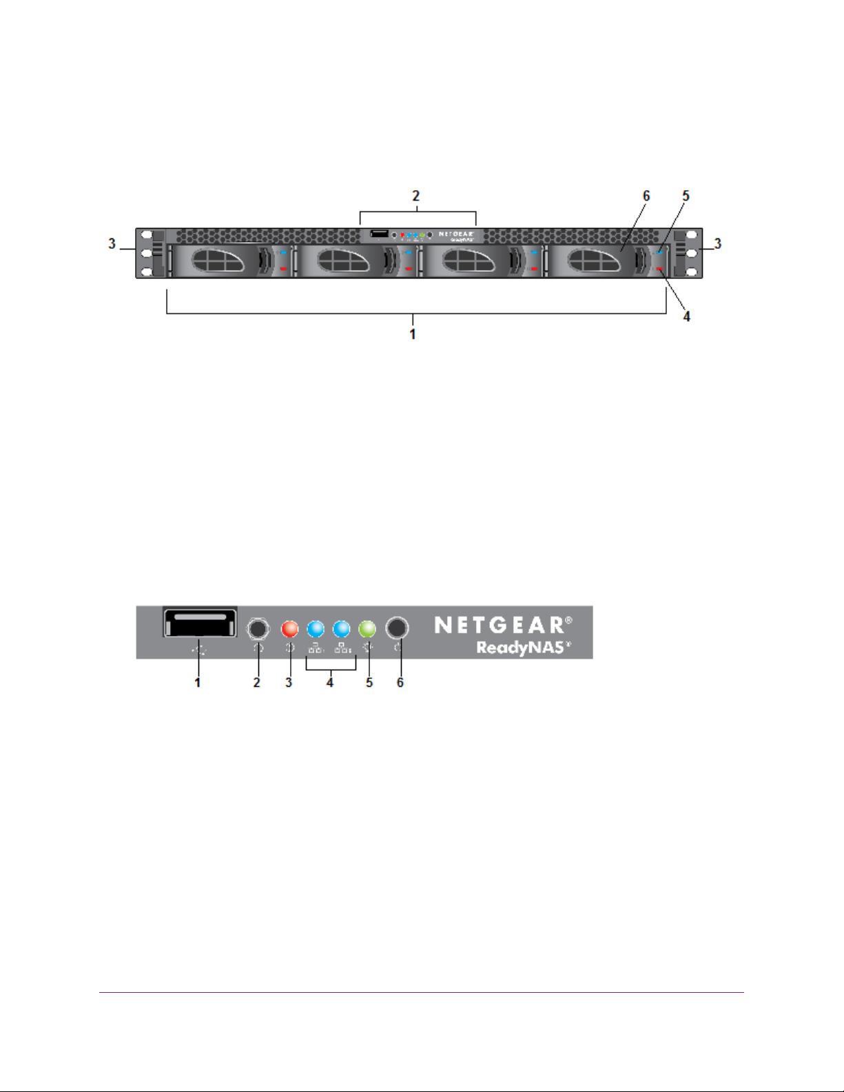
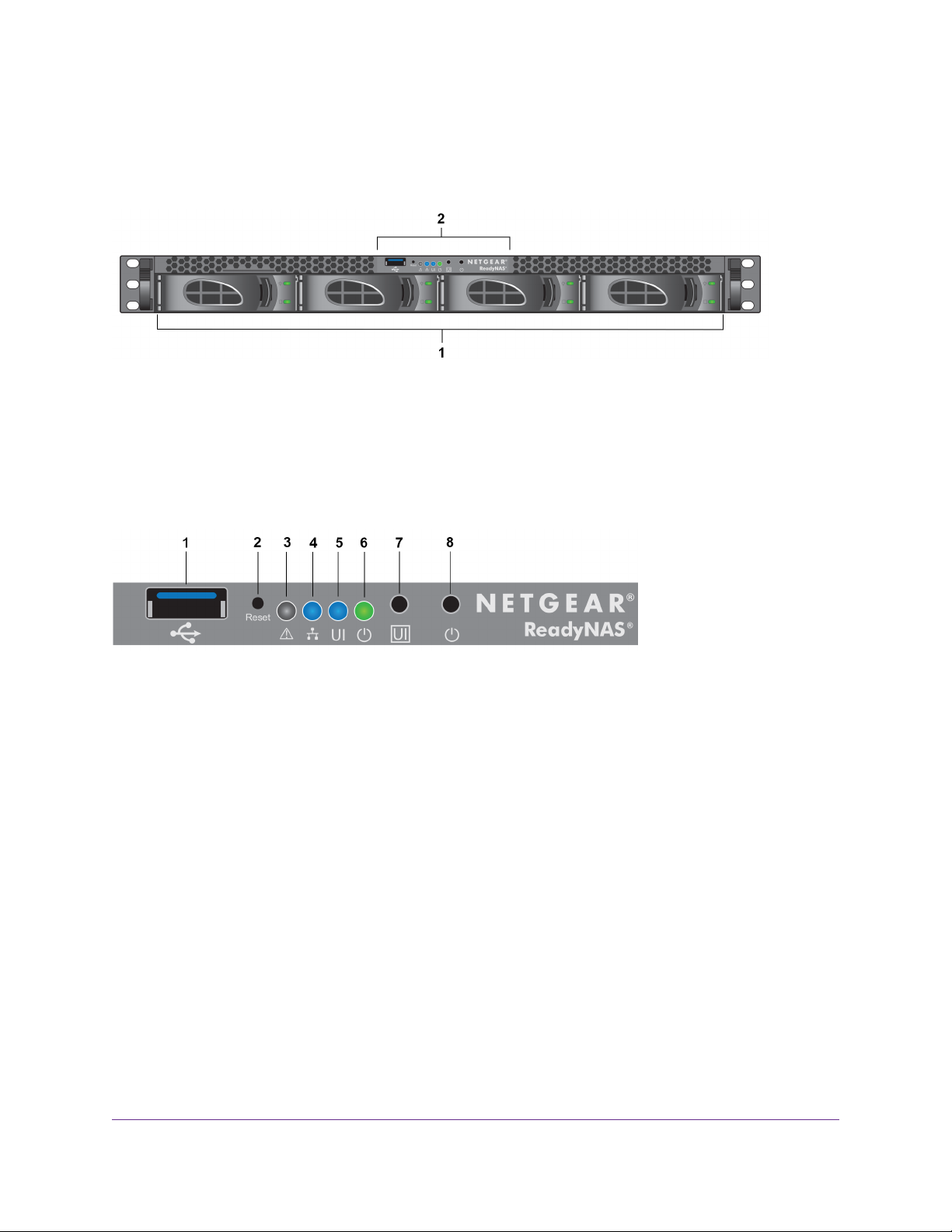
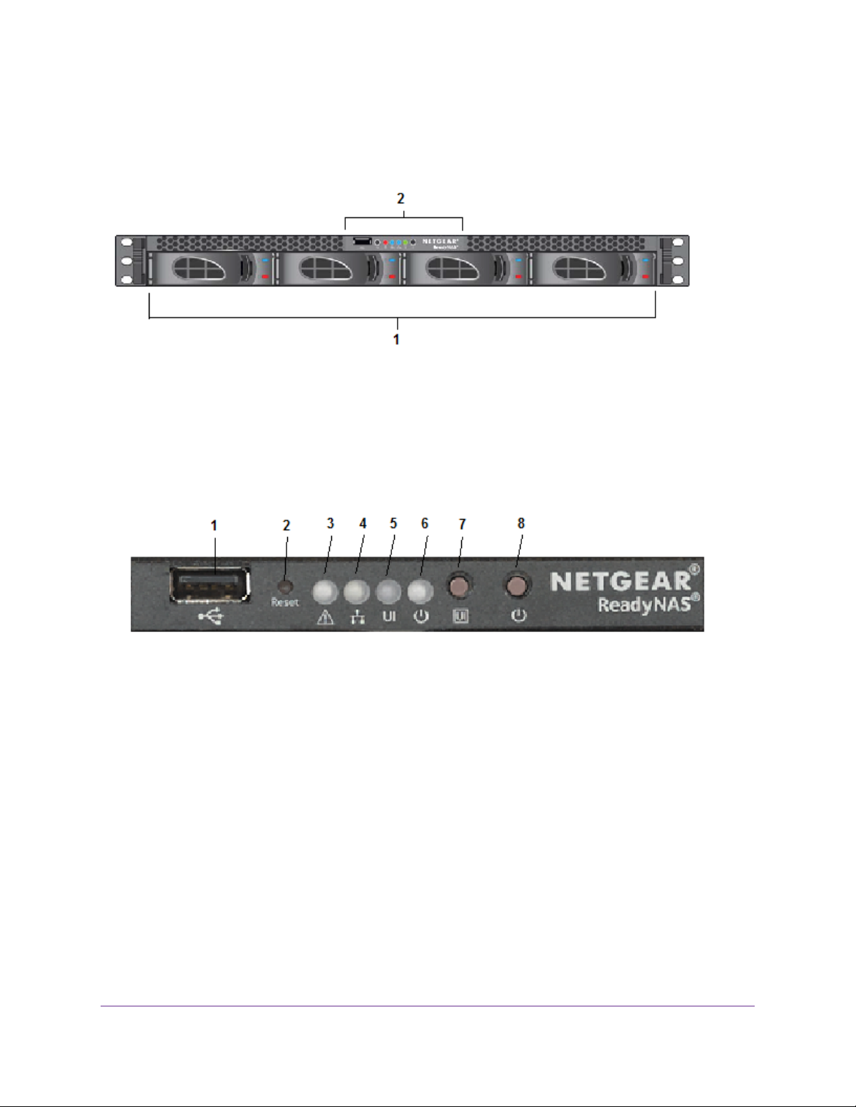
The following figure shows the front panel of the ReadyNAS 2120 and 2120 v2 storage systems.
Figure 1. Front panel
1. Drive bays
2. Control panel
3. Mounting bracket
4. Fault LED
5. Disk Activity LED
6. Disk tray (For more information, see Disk Tray on page 71.)
The following figure shows the control panel in more detail.
Figure 2. Control panel
1. USB 2.0 port
2. Reset button
3. Error LED
4. LAN 1 and LAN 2 LEDs
5. Power LED
6. Power button
ReadyNAS 2120 and 2120 v2
12
Page 13
ReadyNAS OS 6
Rear Panel
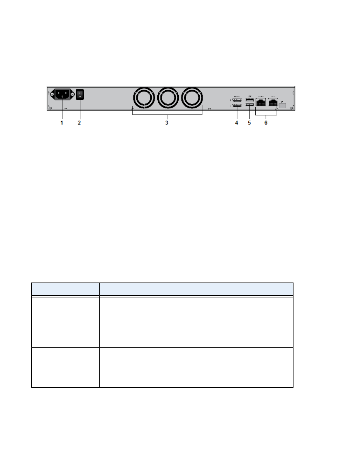
The following figure shows the rear panel of the ReadyNAS 2120 and the 2120 v2 storage systems.
Figure 3. Rear panel
1. Power cable socket
2. Power switch
3. System exhaust fans
4. eSATA ports
5. USB 3.0 ports
6. LAN ports with LED status indicators
Status Information
You can obtain information about the status of your ReadyNAS 2120 or 2120 v2 storage system by re viewing
the LEDs listed in the following table.
Table 1. Status information
DescriptionIndicator
Disk Activity LED (disk tray,
top)
Fault LED (disk tra y, bottom)
The Disk Activity LEDs indicate these states:
• Solid blue. A disk is present.
• Blinking.The disk is active.
• Off. No disk is present.
The Fault LEDs indicate these states:
• Solid red.The disk was removed, failed, or is resynchronizing.
• Off. No disk is active.
ReadyNAS 2120 and 2120 v2
13
Page 14
Table 1. Status information (Continued)
DescriptionIndicator
ReadyNAS OS 6
Error LED (front panel)
LAN 1 and LAN 2 LEDs
(front panel)
LAN port LEDs (rear panel)
The Error LED indicates these states:
• Solid red.The system needs attention. Use the local admin page to determine
the problem. For more inf ormation, see the ReadyNAS OS 6.5 Software Manual,
which is available at http://support.netgear.com/product/ReadyNAS-OS6.
• Off.The system is healthy.
The LAN LEDs indicate these states:
• Solid blue. An Ethernet cable is connected.
• Blinking.The Ethernet link is active.
• Off.There is no Ethernet connection.
Two LED status indicators are built into each LAN port. One LED is green and one
is amber.They indicate port speed and activity as follows:
• Green on, amber off. 1000 Mbps connection speed, no activity.
• Green blinking, amber off. 1000 Mbps connection speed, activity.
• Green off, amber on. 10 Mbps or 100 Mbps connection speed, no activity.
• Green off, amber blinking. 10 Mbps or 100 Mbps connection speed, activity.
• Green off, amber off. No connection.
Power LED (front panel)
The Power LED indicates these states:
• Solid green.The system is powered on.
• Blinking.The system is powering on or powering off.
• Off. Power is not supplied to the system.
Power On and Shut Down
This section describes how to power on and shut down your system. If you must shut down the system, use
one of the preferred shutdown methods whenever possible.
Power On
To power on the system:
1. Connect the system to a power supply.
2. Move the Power switch to the On position.
The Power switch is located on the back panel of the system.
ReadyNAS 2120 and 2120 v2
14
Page 15

ReadyNAS OS 6
Depending on the system's last power state, the system might power on automatically.
Note
For more information, see Power State on page 15.
3. If necessary, press the Power button on the front panel of the system.
The system powers on.
Preferred Shutdown
You can gracefully shut down your system by using the Power button or the ReadyNAS local admin page.
For information about how to gr acefully shut down y our system using the ReadyNAS local admin page, see
the ReadyNAS OS 6.5 Software Manual, which is available at
http://support.netgear.com/product/ReadyNAS-OS6.
To gracefully shut down your system using the Power button:
1. Press the Power button on the front panel of the system.
The Power LED blinks, prompting you to confirm the shutdown.
2. Press the Power button again.
The system shuts down gracefully.
Forced Shutdown
Perform a forced shutdown only if the storage system is not responding.
To perform a forced shutdown:
• Flip the Power switch to the Off position.
The Power switch is located on the back panel of the system.
The system shuts down.
Power State
If the power supply is interrupted due to a power failure, the system returns to its last state once the power
supply is restored, as follows:
• If the system was powered on at the time of the power failure, the system powers on when the power
supply is restored.
• If the system was powered off at the time of the power failure, the system remains off when the power
supply is restored.
Boot Menu
Use the boot menu to restart or troubleshoot your ReadyNAS storage system.Y our storage system provides
the following boot modes:
ReadyNAS 2120 and 2120 v2
15
Page 16
ReadyNAS OS 6
• Normal. Initiates a normal boot process, just like booting using the Power button.
• Factory default. Initiates a short disk test that takes approximately 5 minutes. After the disk test, a
10-minute time-out period begins. During the 10-minute time-out period, you can choose to power off
the storage system without causing any data loss, and the factory default process is canceled. If you
choose not to power off the storage system, after the 10-minute time-out period, the factory default
process begins.
WARNING:
The factory default reboot process resets the storage system to factory
settings, erases all data, resets all defaults, and ref ormats the disk to X-RAID .
To start the factory default process immediately, press the Reset button during the
Note
10-minute time-out period.
• OS reinstall. Reinstalls the firmware from the internal flash to the disks. Use the OS reinstall boot mode
when the system crashes and corrupts some configuration files. OS reinstall boot mode also resets
some settings on your storage system, such as Internet protocol settings and the administrator password,
to defaults.
• Tech support. Boots into a low-level diagnostic mode. Use the tech support boot mode only when a
NETGEAR technical support representative instructs you to do so.
• Volume read only. Mounts a volume as read-only. Use this option when you are attempting to rescue
data off a disk during a disaster recovery.
• Memory test. Performs a memory test. The pass or fail result is reported using the storage system's
LEDs. Contact a NETGEAR technical support representative to interpret memory test results.
• Test disk. Performs an offline full disk test.This process can take four hours or more, depending on
the size of your disks. Any problems are reported in the system logs, which you can view using the local
admin page. For more information about viewing the system logs, see the ReadyNAS OS 6.5 Software
Manual.
To access the boot menu:
1. Power off your system.
2. Using a straightened paper clip, press and hold the Reset button.
3. Press the Power button on the front panel of the system.
The system powers on.
4. Continue to press the Reset button for about five seconds until the Power LED is solid green and the
Error LED, LAN 1 LED, and LAN 2 LED are blinking.
5. Press and release the Reset button to scroll through the boot mode menu.
Each press and release scrolls forward to the next item in the boot mode menu.
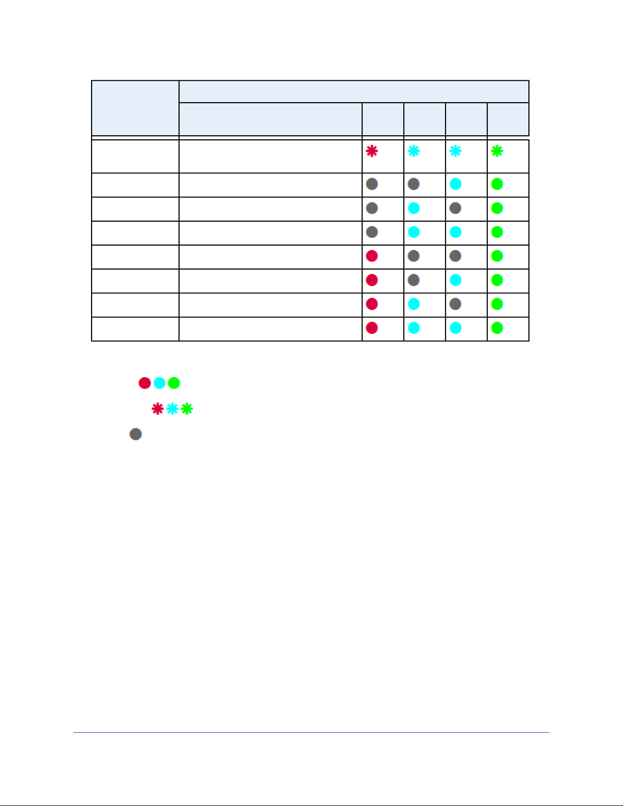
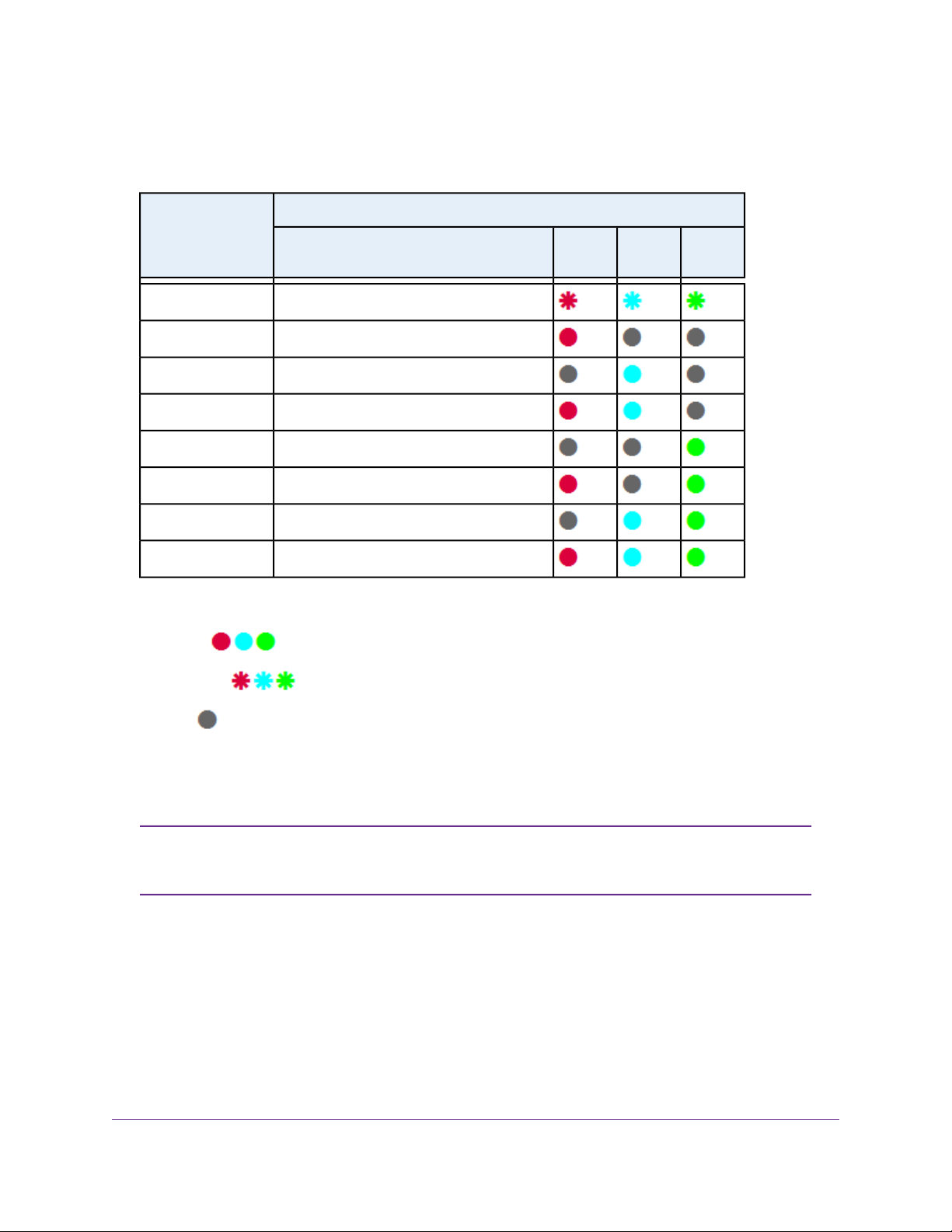
The storage system shows the boot mode options using the LEDs, as described in the following table:
ReadyNAS 2120 and 2120 v2
16
Page 17
ReadyNAS OS 6
Status IndicatorBoot Mode
Boot menu
Legend:
•
Solid:
Description
Error LED and both LAN LEDs blink. Power
LED lights.
LAN 2 and Power LEDs light.Normal
LAN 1 and Power LEDs light.Factory default
Both LAN LEDs and the Power LED light.OS reinstall
Error and Power LEDs light.Tech support
Error, LAN 2, and Power LEDs light.Volume read only
Error, LAN 1, and Power LEDs light.Memory test
All four LEDs light.Test disk
Error
LED
LAN 1
LED
LAN 2
LED
Power
LED
•
Blinking:
•
Off:
6. Press and hold the Reset button for five seconds to confirm your boot menu selection.
The system boots in the selected boot mode.
Rack Mounting
You can rack-mount the ReadyNAS 2120 and 2120 v2 storage systems using the included rack-mount ears.
Alternatively, you can use the optional sliding rail kit, order number RRAIL04-10000S. For instructions, see
the 1U Rail Installation Guide, which is available at http://support.netgear.com/product/ReadyNAS-OS6.
ReadyNAS 2120 and 2120 v2
17
Page 18

ReadyNAS 2304
This chapter describes the physical features of the ReadyNAS 2304 storage system. It includes the following
sections:
• Front Panel on page 19
• Rear Panel on page 20
• Status Information on page 21
• Power On and Shut Down on page 22
• Boot Menu on page 24
• Rack Mounting on page 25
3
18
Page 19
ReadyNAS OS 6
Front Panel
The following figure shows the front panel of the ReadyNAS 2304.
Figure 4. Front panel
1. Drive bays with disk status LEDs
2. Control panel
The following figure shows the control panel in more detail.
Figure 5. Control panel
1. USB 3.0 port
2. Reset button
3. Health LED
4. LAN LED
5. Unit identifier (UID) LED
6. Power LED
7. Unit identifier (UID) button
8. Power button
Each drive bay features a latch that releases the pop-out tray handle, as shown in the following figure.
ReadyNAS 2304
19
Page 20
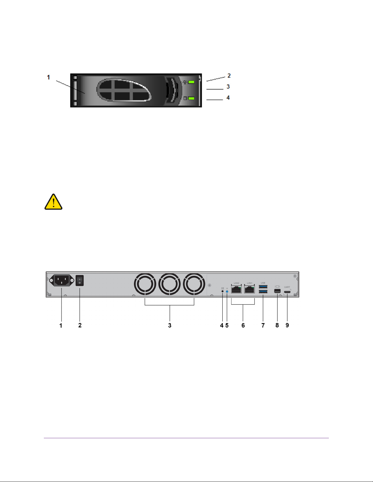
Figure 6. Drive bay
1. Disk tray handle
2. Disk Present LED
3. Disk tray release latch
4. Disk Activity or Fault LED
ReadyNAS OS 6
WARNING:
No matter how many hard drives are installed in y our system, ensure that all drive
trays remain in the drive bays to maintain proper airflow.
Rear Panel
The following figure shows the rear panel of the ReadyNAS 2304 storage system.
Figure 7. Rear panel
1. Power cable socket
2. Power switch
3. Three system exhaust fans
4. Unit Identifier (UID) button
5. Unit Identifier (UID) LED
6. Two 1-gigabit LAN ports with LED status indicators
7. Two USB 3.0 ports
ReadyNAS 2304
20
Page 21

ReadyNAS OS 6
8. One display port
9. One micro USB console connector (marked UART)
Status Information
You can obtain information about the status of your system by re viewing the indicators listed in the f ollo wing
table.
Table 2. Status indicators
DescriptionIndicator
Power LED (control panel)
UI LED (control panel)
Health LED (control panel)
The Power LED indicates these states:
• Green.The system is powered on.
• Blinking.The system is powering on or powering off.
• Off. Power is not supplied to the system.
The UI (Unit Identification) LED indicates these states:
• Blue. Software or manual identification is on.
• Off. Identification is not requested by software or manually when the UI button is
pressed.
Pressing the UI button on either the control panel or the rear panel toggles the UI
LEDs on the control panel and the rear panel. Use this in a situation such as a
densely populated rack when you are working from both the front and back of the
server.
The Health LED indicates these states:
• Red.The system needs attention. Use the local admin page to determine the
problem. For more inf ormation, see the ReadyNAS OS 6.5 Software Manual, which
is available at http://support.netgear.com/product/ReadyNAS-OS6.
• Off.The system is healthy.
LAN LED (control panel)
The LAN LED indicates these states:
• Blue. One or more Ethernet ports are linked.
• Blinking. One or more Ethernet ports are active.
• Off.There is no Ethernet connection.
ReadyNAS 2304
21
Page 22

Table 2. Status indicators (Continued)
DescriptionIndicator
ReadyNAS OS 6
Disk LEDs (disk trays)
UI LED (rear panel)
LAN port LEDs (rear panel)
The top LED indicates disk status, as follows:
• Green. A disk is present and in use.
• Off. No disk is present, or not in use.
The bottom LED indicates disk activity as follows:
• Blinking green.The disk is being accessed.
• Off.The disk is idling.
• Red.The disk was removed, failed, or is resynchronizing.
The UI (Unit Identifier) LED indicates these states:
• Blue. Software or manual identification is on.
• Off. Identification is not requested by software or manually when the UI button is
pressed.
Pressing the UI button on either the control panel or the rear panel toggles the UI
LEDs on the control panel and the rear panel. Use this in a situation such as a
densely populated rack when you are working from both the front and back of the
server.
Two LED status indicators are built into each LAN port. The left LED is a single-color
LED and indicates whether activity occurs on the port.The right LED is a bi-color LED
and indicates the port speed.Together, these LEDs indicate activity and port speed as
follows:
• Left LED solid amber, right LED solid green. 1 Gbps connection speed, no
activity.
• Left LED blinking amber, right LED solid green. 1 Gbps connection speed,
activity.
• Left LED solid amber, right LED solid amber. 100 Mbps connection speed, no
activity.
• Left LED blinking amber, right LED solid amber. 10 Mbps connection
speed, activity.
• Left LED solid amber, right LED off. 10 Mbps connection speed, no activity.
• Left LED blinking amber, right LED off. 10 Mbps connection speed, activity.
• Left LED off, right LED off. No connection.
Power On and Shut Down
This section describes how to power on and shut down your system. If you must shut down the system, use
one of the preferred shutdown methods whenever possible.
ReadyNAS 2304
22
Page 23

ReadyNAS OS 6
Power On
To power on the system:
1. Connect the system to a power supply.
Depending on the system's last power state, the system might power on automatically.
Note
For more information, see on page ?.
2. If necessary, press the Power button on the front panel of the system.
The system powers on.
Preferred Shutdown
You can gracefully shut down your system by using the Power button or the ReadyNAS local admin page.
For information about how to gr acefully shut down y our system using the ReadyNAS local admin page, see
the ReadyNAS OS 6.5 Software Manual, which is available at
http://support.netgear.com/product/ReadyNAS-OS6.
To gracefully shut down your system using the Power button:
1. Press the Power button on the front panel of the system.
The Power LED blinks, prompting you to confirm the shutdown.
2. Press the Power button again.
The system shuts down gracefully.
Forced Shutdown
Perform a forced shutdown only if the storage system is not responding.
To perform a forced shutdown:
Press and hold the Power button on the front panel for more than four seconds.
The system shuts down.
Power State
If the power supply is interrupted due to a power failure, the system returns to its last state once the power
supply is restored, as follows:
• If the system was powered on at the time of the power failure, the system powers on when the power
supply is restored.
• If the system was powered off at the time of the power failure, the system remains off when the power
supply is restored.
ReadyNAS 2304
23
Page 24
ReadyNAS OS 6
Boot Menu
Use the boot menu to restart or troubleshoot your ReadyNAS storage system.Y our storage system provides
the following boot modes:
• Normal. Initiates a normal boot process, just like booting using the Power button.
• Factory default. Initiates a short disk test that takes approximately 5 minutes. After the disk test, a
10-minute time-out period begins. During the 10-minute time-out period, you can choose to power off
the storage system without causing any data loss, and the factory default process is canceled. If you
choose not to power off the storage system, after the 10-minute time-out period, the factory default
process begins.
WARNING:
The factory default reboot process resets the storage system to factory
settings, erases all data, resets all defaults, and ref ormats the disk to X-RAID .
To start the factory default process immediately, press the Reset button during the
Note
10-minute time-out period.
• OS reinstall. Reinstalls the firmware from the internal flash to the disks. Use the OS reinstall boot mode
when the system crashes and corrupts some configuration files. OS reinstall boot mode also resets
some settings on your storage system, such as Internet protocol settings and the administrator password,
to defaults.
• Tech support. Boots into a low-level diagnostic mode. Use the tech support boot mode only when a
NETGEAR technical support representative instructs you to do so.
• Volume read only. Mounts a volume as read-only. Use this option when you are attempting to rescue
data off a disk during a disaster recovery.
• Memory test. Performs a memory test. The pass or fail result is reported using the storage system's
LEDs. During the test the Health LED and the UI LED light alternately. If a memory error is found, the
Health LED and UI LED blink at the same time.
• Test disk. Performs an offline full disk test.This process can take four hours or more, depending on
the size of your disks. Any problems are reported in the system logs, which you can view using the local
admin page. For more information about viewing the system logs, see the ReadyNAS OS 6.5 Software
Manual, which is available at http://support.netgear.com/product/ReadyNAS-OS6.
To access the boot menu:
1. Power off your system.
2. Using a straightened paper clip, press and hold the Reset button on the control panel.
3. Press and continue pressing the Power b utton on the front panel of the system until the system po wers
on and either the Power LED stops blinking or the Power, UI, and Health LEDs are lit.
It takes approximately one minute for the system to enter boot mode.Note
ReadyNAS 2304
24
Page 25
ReadyNAS OS 6
4. Press and hold the Reset button, releasing after about one second, to scroll through the boot menu
modes.
The storage system shows the boot mode options using the LEDs, as described in the following table:
Status IndicatorBoot Mode
Legend:
•
Solid:
•
Blinking:
Description
Power, UI, and Health LEDs blink.Boot menu
Health LED lights.Normal
UI LED lights.Factory default
UI and Health LEDs light.OS reinstall
Power LED lights.Tech support
Power and Health LEDs light.Volume read only
Power and UI LEDs light.Memory test
Power, UI, and Health LEDs light.Test disk
LED
UI LEDHealth
Power
LED
•
Off:
5. Press and hold the Reset button for four seconds to confirm your boot menu selection.
The system boots in the selected boot mode.
If you do not hold the Reset button long enough, the press moves the system to the
Note
next selection. Repeat the press and hold for one second to scroll through to your
desired selection.
Rack Mounting
You can rack-mount the ReadyNAS 2304 using the included rack-mount ears.
Alternatively, you can use the optional sliding rail kit, order number RRAIL04-10000S. For instructions see
the 1U Rail Installation Guide, which is available at http://support.netgear.com/product/ReadyNAS-OS6.
ReadyNAS 2304
25
Page 26

ReadyNAS 3130
This chapter describes the physical features of the ReadyNAS 3130 storage system. It includes the following
sections:
• Front Panel on page 27
• Rear Panel on page 28
• Status Information on page 29
• Power On and Shut Down on page 30
• Boot Menu on page 31
• Rack Mounting on page 33
4
26
Page 27
ReadyNAS OS 6
Front Panel
The following figure shows the front panel of the ReadyNAS 3130 storage system.
Figure 8. Front panel
1. Drive bays with disk status LEDs
2. Control panel
The following figure shows the control panel in more detail.
Figure 9. Control panel
1. USB 2.0 port
2. Reset button
3. Health LED
4. LAN LED
5. Unit Identifier (UID) LED
6. Power LED
7. Unit Identifier (UID) button
8. Power button
Each drive bay features a latch that releases the pop-out tray handle, as shown in the following figure.
ReadyNAS 3130
27
Page 28
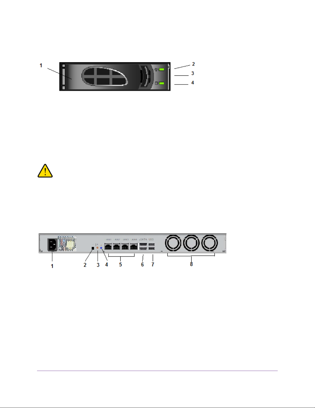
Figure 10. Drive bay
1. Disk tray handle
2. Disk Present LED
3. Disk tray release latch
4. Disk Activity or Fault LED
ReadyNAS OS 6
WARNING:
No matter how many hard drives are installed in y our system, ensure that all drive
trays remain in the drive bays to maintain proper airflow.
Rear Panel
The following figure shows the rear panel of the ReadyNAS 3130 storage system.
Figure 11. Rear panel
1. Power cable socket
2. Reserved for NETGEAR support
3. Unit Identifier (UID) button
4. Unit Identifier (UID) LED
5. Four 1-gigabit LAN ports with LED status indicators
6. Two eSATA ports
7. Two USB 3.0 ports
8. Three system exhaust fans
ReadyNAS 3130
28
Page 29

ReadyNAS OS 6
Status Information
You can obtain information about the status of your system by re viewing the indicators listed in the f ollo wing
table.
Table 3. Status indicators
DescriptionIndicator
Power LED (control panel)
UI LED (control panel)
Health LED (control panel)
The Power LED indicates these states:
• Green.The system is powered on.
• Blinking.The system is powering on or powering off.
• Off. Power is not supplied to the system.
The UI (Unit Identifier) LED indicates these states:
• Blue. Software or manual identification is on.
• Off. Identification is not requested by software or manually when the UI
button is pressed.
Pressing the UI button on either the control panel or the rear panel toggles
the UI LEDs on the control panel and the rear panel. Use this in a situation
such as a densely populated rack when you are working from both the front
and back of the server.
The Health LED indicates these states:
• Red.The system needs attention. Use the local admin page to determine
the problem. For more information, see the ReadyNAS OS 6.5 Software
Manual, which is available at
http://support.netgear.com/product/ReadyNAS-OS6.
• Off.The system is healthy.
LAN LED (control panel)
Disk LEDs (disk trays)
The LAN LED indicates these states:
• Blue. One or more Ethernet ports are linked.
• Blinking. One or more Ethernet ports are active.
• Off.There is no Ethernet connection.
The top LED indicates disk status, as follows:
• Green. A disk is present and in use.
• Off. No disk is present, or is not in use.
The bottom LED indicates disk activity as follows:
• Blinking green.The disk is being accessed.
• Off.The disk is idling.
• Red.The disk was removed, failed, or is resynchronizing.
ReadyNAS 3130
29
Page 30
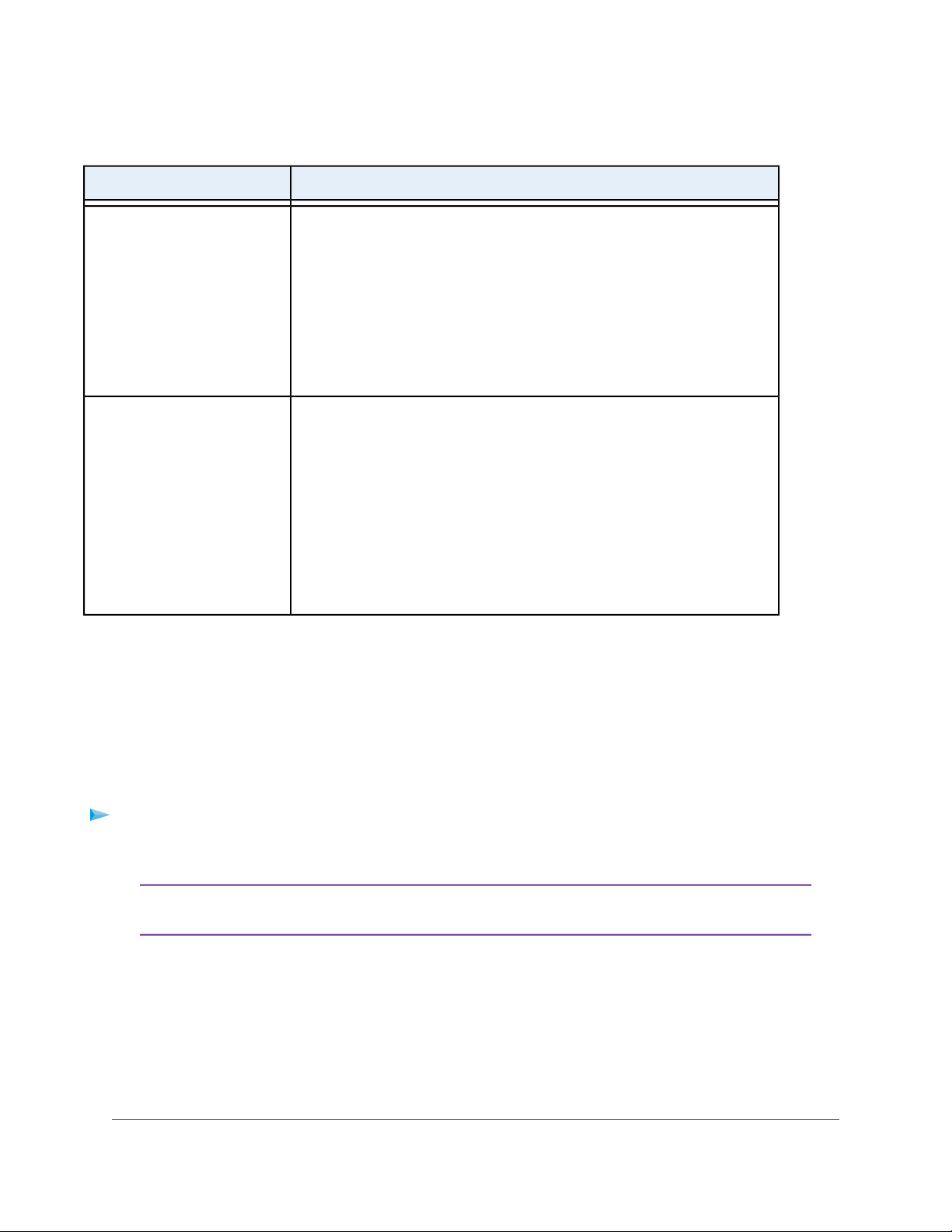
Table 3. Status indicators (Continued)
DescriptionIndicator
ReadyNAS OS 6
UI LED (rear panel)
LAN port LEDs (rear panel)
The UI (Unit Identifier) LED indicates these states:
• Blue. Software or manual identification is on.
• Off. Identification is not requested by software or manually when the UI
button is pressed.
Pressing the UI button on either the control panel or the rear panel toggles
the UI LEDs on the control panel and the rear panel. Use this in a situation
such as a densely populated rack when you are working from both the front
and back of the server.
Two LED status indicators are built into each LAN port. One LED is green and
one is amber.They indicate port speed and activity as follows:
• Green on, amber off. 1000 Mbps connection speed, no activity.
• Green blinking, amber off. 1000 Mbps connection speed, activity.
• Green off, amber on. 10 Mbps or 100 Mbps connection speed, no activity.
• Green off, amber blinking. 10 Mbps or 100 Mbps connection
speed, activity.
• Green off, amber off. No connection.
Power On and Shut Down
This section describes how to power on and shut down your system. If you must shut down the system, use
one of the preferred shutdown methods whenever possible.
Power On
To power on the system:
1. Connect the system to a power supply.
Depending on the system's last power state, the system might power on automatically.
Note
For more information, see Power State on page 31.
2. If necessary, press the Power button on the front panel of the system.
The system powers on.
Preferred Shutdown
You can gracefully shut down your system by using the Power button or the ReadyNAS local admin page.
ReadyNAS 3130
30
Page 31

ReadyNAS OS 6
For information about how to gr acefully shut down y our system using the ReadyNAS local admin page, see
the ReadyNAS OS 6.5 Software Manual, which is available at
http://support.netgear.com/product/ReadyNAS-OS6.
To gracefully shut down your system using the Power button:
1. Press the Power button on the front panel of the system.
The Power LED blinks, prompting you to confirm the shutdown.
2. Press the Power button again.
The system shuts down gracefully.
Forced Shutdown
Perform a forced shutdown only if the storage system is not responding.
To perform a forced shutdown:
• Press and hold the Power button on the front panel for more than four seconds.
The system shuts down.
Power State
If the power supply is interrupted due to a power failure, the system returns to its last state once the power
supply is restored, as follows:
• If the system was powered on at the time of the power failure, the system powers on when the power
supply is restored.
• If the system was powered off at the time of the power failure, the system remains off when the power
supply is restored.
Boot Menu
Use the boot menu to restart or troubleshoot your ReadyNAS storage system.Y our storage system provides
the following boot modes:
• Normal. Initiates a normal boot process, just like booting using the Power button.
• Factory default. Initiates a short disk test that takes approximately 5 minutes. After the disk test, a
10-minute time-out period begins. During the 10-minute time-out period, you can choose to power off
the storage system without causing any data loss, and the factory default process is canceled. If you
choose not to power off the storage system, after the 10-minute time-out period, the factory default
process begins.
WARNING:
The factory default reboot process resets the storage system to factory
settings, erases all data, resets all defaults, and ref ormats the disk to X-RAID .
ReadyNAS 3130
31
Page 32

ReadyNAS OS 6
To start the factory default process immediately, press the Reset button during the
Note
10-minute time-out period.
• OS reinstall. Reinstalls the firmware from the internal flash to the disks. Use the OS reinstall boot mode
when the system crashes and corrupts some configuration files. OS reinstall boot mode also resets
some settings on your storage system, such as Internet protocol settings and the administrator password,
to defaults.
• Tech support. Boots into a low-level diagnostic mode. Use the tech support boot mode only when a
NETGEAR technical support representative instructs you to do so.
• Volume read only. Mounts a volume as read-only. Use this option when you are attempting to rescue
data off a disk during a disaster recovery.
• Memory test. Performs a memory test. The pass or fail result is reported using the storage system's
LEDs. During the test the Health LED and the UI LED light alternately. If a memory error is found, the
Health LED and UI LED blink at the same time.
• Test disk. Performs an offline full disk test.This process can take four hours or more, depending on
the size of your disks. Any problems are reported in the system logs, which you can view using the local
admin page. For more information about viewing the system logs, see the ReadyNAS OS 6.5 Software
Manual, which is available at http://support.netgear.com/product/ReadyNAS-OS6.
To access the boot menu:
1. Power off your system.
2. Using a straightened paper clip, press and hold the Reset button on the control panel.
3. Press and continue pressing the Power b utton on the front panel of the system until the system po wers
on and either the Power LED stops blinking or the Power, UI, and Health LEDs are lit.
It takes approximately one minute for the system to enter boot mode.Note
4. Press and hold the Reset button, releasing after about one second, to scroll through the boot menu
modes.
The storage system shows the boot mode options using the LEDs, as described in the following table:
Status IndicatorBoot Mode
Description
Power, UI, and Health LEDs blink.Boot menu
Health LED lights.Normal
UI LEDHealth
LED
Power
LED
UI LED lights.Factory default
UI and Health LEDs light.OS reinstall
Power LED lights.Tech support
ReadyNAS 3130
32
Page 33

(Continued)
ReadyNAS OS 6
Status IndicatorBoot Mode
Description
LED
Power and Health LEDs light.Volume read only
Power and UI LEDs light.Memory test
Power, UI, and Health LEDs light.Test disk
Legend:
•
Solid:
•
Blinking:
•
Off:
5. Press and hold the Reset button for four seconds to confirm your boot menu selection.
The system boots in the selected boot mode.
If you do not hold the Reset button long enough, the press moves the system to the
Note
next selection. Repeat the press and hold for one second to scroll through to your
desired selection.
UI LEDHealth
Power
LED
Rack Mounting
You can rack-mount the ReadyNAS 3130 using the included rack-mount ears.
Alternatively, you can use the optional sliding rail kit, order number RRAIL04-10000S. For instructions, see
the 1U Rail Installation Guide, which is available at http://support.netgear.com/product/ReadyNAS-OS6.
ReadyNAS 3130
33
Page 34

ReadyNAS 3138
This chapter describes the physical features of the ReadyNAS 3138 storage system. It includes the following
sections:
• Front Panel on page 35
• Rear Panel on page 36
• Status Information on page 37
• Power On and Shut Down on page 38
• Boot Menu on page 39
• Rack Mounting on page 41
5
34
Page 35

ReadyNAS OS 6
Front Panel
The following figure shows the front panel of the ReadyNAS 3138.
Figure 12. Front panel
1. Drive bays with disk status LEDs
2. Control panel
The following figure shows the control panel in more detail.
Figure 13. Control panel
1. USB 2.0 port
2. Reset button
3. Health LED
4. LAN LED
5. Unit identifier (UID) LED
6. Power LED
7. Unit identifier (UID) button
8. Power button
Each drive bay features a latch that releases the pop-out tray handle, as shown in the following figure.
ReadyNAS 3138
35
Page 36

Figure 14. Drive bay
1. Disk tray handle
2. Disk Present LED
3. Disk tray release latch
4. Disk Activity or Fault LED
ReadyNAS OS 6
WARNING:
No matter how many hard drives are installed in y our system, ensure that all drive
trays remain in the drive bays to maintain proper airflow.
Rear Panel
The following figure shows the rear panel of the ReadyNAS 3138 storage system.
Figure 15. Rear panel
1. Power cable socket
2. Reserved for NETGEAR support
3. Unit Identifier (UID) button
4. Unit Identifier (UID) LED
5. Four 1-gigabit LAN ports with LED status indicators
6. Two eSATA ports
7. Two USB 3.0 ports
8. Three system exhaust fans
ReadyNAS 3138
36
Page 37

ReadyNAS OS 6
Status Information
You can obtain information about the status of your system by re viewing the indicators listed in the f ollo wing
table.
Table 4. Status indicators
DescriptionIndicator
Power LED (control panel)
UI LED (control panel)
Health LED (control panel)
The Power LED indicates these states:
• Green.The system is powered on.
• Blinking.The system is powering on or powering off.
• Off. Power is not supplied to the system.
The UI (Unit Identification) LED indicates these states:
• Blue. Software or manual identification is on.
• Off. Identification is not requested by software or manually when the UI
button is pressed.
Pressing the UI button on either the control panel or the rear panel toggles
the UI LEDs on the control panel and the rear panel. Use this in a situation
such as a densely populated rack when you are working from both the front
and back of the server.
The Health LED indicates these states:
• Red.The system needs attention. Use the local admin page to determine
the problem. For more information, see the ReadyNAS OS 6.5 Software
Manual, which is available at
http://support.netgear.com/product/ReadyNAS-OS6.
• Off.The system is healthy.
LAN LED (control panel)
Disk LEDs (disk trays)
The LAN LED indicates these states:
• Blue. One or more Ethernet ports are linked.
• Blinking. One or more Ethernet ports are active.
• Off.There is no Ethernet connection.
The top LED indicates disk status, as follows:
• Green. A disk is present and in use.
• Off. No disk is present, or not in use.
The bottom LED indicates disk activity as follows:
• Blinking green.The disk is being accessed.
• Off.The disk is idling.
• Red.The disk was removed, failed, or is resynchronizing.
ReadyNAS 3138
37
Page 38

Table 4. Status indicators (Continued)
DescriptionIndicator
ReadyNAS OS 6
UI LED (rear panel)
LAN port LEDs (rear panel)
The UI (Unit Identifier) LED indicates these states:
• Blue. Software or manual identification is on.
• Off. Identification is not requested by software or manually when the UI
button is pressed.
Pressing the UI button on either the control panel or the rear panel toggles
the UI LEDs on the control panel and the rear panel. Use this in a situation
such as a densely populated rack when you are working from both the front
and back of the server.
Two LED status indicators are built into each LAN port. One LED is green and
one is amber.They indicate port speed and activity as follows:
• Green on, amber off. 1000 Mbps connection speed, no activity.
• Green blinking, amber off. 1000 Mbps connection speed, activity.
• Green off, amber on. 10 Mbps or 100 Mbps connection speed, no activity.
• Green off, amber blinking. 10 Mbps or 100 Mbps connection
speed, activity.
• Green off, amber off. No connection.
Power On and Shut Down
This section describes how to power on and shut down your system. If you must shut down the system, use
one of the preferred shutdown methods whenever possible.
Power On
To power on the system:
1. Connect the system to a power supply.
Depending on the system's last power state, the system might power on automatically.
Note
For more information, see Power State on page 39.
2. If necessary, press the Power button on the front panel of the system.
The system powers on.
Preferred Shutdown
You can gracefully shut down your system by using the Power button or the ReadyNAS local admin page.
ReadyNAS 3138
38
Page 39

ReadyNAS OS 6
For information about how to gr acefully shut down y our system using the ReadyNAS local admin page, see
the ReadyNAS OS 6.5 Software Manual, which is available at
http://support.netgear.com/product/ReadyNAS-OS6.
To gracefully shut down your system using the Power button:
1. Press the Power button on the front panel of the system.
The Power LED blinks, prompting you to confirm the shutdown.
2. Press the Power button again.
The system shuts down gracefully.
Forced Shutdown
Perform a forced shutdown only if the storage system is not responding.
To perform a forced shutdown:
• Press and hold the Power button on the front panel for more than four seconds.
The system shuts down.
Power State
If the power supply is interrupted due to a power failure, the system returns to its last state once the power
supply is restored, as follows:
• If the system was powered on at the time of the power failure, the system powers on when the power
supply is restored.
• If the system was powered off at the time of the power failure, the system remains off when the power
supply is restored.
Boot Menu
Use the boot menu to restart or troubleshoot your ReadyNAS storage system.Y our storage system provides
the following boot modes:
• Normal. Initiates a normal boot process, just like booting using the Power button.
• Factory default. Initiates a short disk test that takes approximately 5 minutes. After the disk test, a
10-minute time-out period begins. During the 10-minute time-out period, you can choose to power off
the storage system without causing any data loss, and the factory default process is canceled. If you
choose not to power off the storage system, after the 10-minute time-out period, the factory default
process begins.
WARNING:
The factory default reboot process resets the storage system to factory
settings, erases all data, resets all defaults, and ref ormats the disk to X-RAID .
ReadyNAS 3138
39
Page 40

ReadyNAS OS 6
To start the factory default process immediately, press the Reset button during the
Note
10-minute time-out period.
• OS reinstall. Reinstalls the firmware from the internal flash to the disks. Use the OS reinstall boot mode
when the system crashes and corrupts some configuration files. OS reinstall boot mode also resets
some settings on your storage system, such as Internet protocol settings and the administrator password,
to defaults.
• Tech support. Boots into a low-level diagnostic mode. Use the tech support boot mode only when a
NETGEAR technical support representative instructs you to do so.
• Volume read only. Mounts a volume as read-only. Use this option when you are attempting to rescue
data off a disk during a disaster recovery.
• Memory test. Performs a memory test. The pass or fail result is reported using the storage system's
LEDs. During the test the Health LED and the UI LED light alternately. If a memory error is found, the
Health LED and UI LED blink at the same time.
• Test disk. Performs an offline full disk test.This process can take four hours or more, depending on
the size of your disks. Any problems are reported in the system logs, which you can view using the local
admin page. For more information about viewing the system logs, see the ReadyNAS OS 6.5 Software
Manual, which is available at http://support.netgear.com/product/ReadyNAS-OS6.
To access the boot menu:
1. Power off your system.
2. Using a straightened paper clip, press and hold the Reset button on the control panel.
3. Press and continue pressing the Power b utton on the front panel of the system until the system po wers
on and either the Power LED stops blinking or the Power, UI, and Health LEDs are lit.
It takes approximately one minute for the system to enter boot mode.Note
4. Press and hold the Reset button, releasing after about one second, to scroll through the boot menu
modes.
The storage system shows the boot mode options using the LEDs, as described in the following table:
Status IndicatorBoot Mode
Description
Power, UI, and Health LEDs blink.Boot menu
Health LED lights.Normal
UI LEDHealth
LED
Power
LED
UI LED lights.Factory default
UI and Health LEDs light.OS reinstall
Power LED lights.Tech support
ReadyNAS 3138
40
Page 41

(Continued)
ReadyNAS OS 6
Status IndicatorBoot Mode
Description
LED
Power and Health LEDs light.Volume read only
Power and UI LEDs light.Memory test
Power, UI, and Health LEDs light.Test disk
Legend:
•
Solid:
•
Blinking:
•
Off:
5. Press and hold the Reset button for four seconds to confirm your boot menu selection.
The system boots in the selected boot mode.
If you do not hold the Reset button long enough, the press moves the system to the
Note
next selection. Repeat the press and hold for one second to scroll through to your
desired selection.
UI LEDHealth
Power
LED
Rack Mounting
You can rack-mount the ReadyNAS 3138 using the included rack-mount ears.
Alternatively, you can use the optional sliding rail kit, order number RRAIL04-10000S. For instructions see
the 1U Rail Installation Guide, which is available at http://support.netgear.com/product/ReadyNAS-OS6.
ReadyNAS 3138
41
Page 42

ReadyNAS 3220 and 4220
This chapter describes the physical features of the ReadyNAS 3220 and ReadyNAS 4220 storage systems. It
includes the following sections:
• Front Panel on page 43
• ReadyNAS 3220 Rear Panel on page 44
• ReadyNAS 4220 Rear Panel on page 45
• Status Information on page 45
• Boot Menu on page 47
• Rack-Mount Setup on page 49
6
42
Page 43

ReadyNAS OS 6
Front Panel
The following figure shows the front panel of the ReadyNAS 3220 and 4220 storage systems.
Figure 16. Front panel
1. Drive bays with disk status LEDs
2. Control panel
The following figure shows the control panel in more detail.
Figure 17. Control panel
1. Power LED
2. Power button
3. Unit Identifier (UID) button
4. Reset button
5. Unit Identifier (UID) LED
6. Health LED
ReadyNAS 3220 and 4220
43
Page 44

ReadyNAS OS 6
7. LAN LEDs
8. Disk Drive Power LED
9. Disk Drive Activity LED
10. USB 2.0 ports
Each drive bay features a latch that releases the pop-out tray handle, as shown in the following figure.
Figure 18. Disk tray handle and release latch
1. Disk tray handle
2. Disk tray release latch
WARNING:
No matter how many hard drives are installed in y our system, ensure that all drive
trays remain in the drive bays to maintain proper airflow.
ReadyNAS 3220 Rear Panel
The following figure shows the rear panel of the ReadyNAS 3220 storage systems.
Figure 19. Rear panel
1. Power supplies
2. Power Supply LEDs
3. Unit Identifier (UID) LED
4. eSATA ports
ReadyNAS 3220 and 4220
44
Page 45

ReadyNAS OS 6
5. 1-gigabit LAN ports with LED status indicators
6. Console port
7. USB 3.0 ports
ReadyNAS 4220 Rear Panel
The following figure shows the rear panel of the ReadyNAS 4220 storage system.
Figure 20. Rear panel
1. Power supplies
2. Power Supply LEDs
3. Unit Identifier (UID) LED
4. eSATA ports
5. 1-gigabit LAN ports with LED status indicators
6. Console port
7. USB 2.0 ports
8. 10-gigabit LAN ports with LED status indicators
Status Information
You can obtain information about the status of your system by re viewing the indicators listed in the f ollo wing
table.
ReadyNAS 3220 and 4220
45
Page 46

Table 5. Status indicators
ReadyNAS OS 6
DescriptionIndicator
Power LED (control panel)
UI LED (control panel)
Health LED (control panel)
LAN LEDs (control panel)
The Power LED indicates these states:
• Green.The system is powered on.
• Amber.The system is in standby mode.
• Off.The system is powered off.
The UI LED indicates these states:
• Blue.The system is identified: The UI button was pressed and the UID
LED on the rear panel is lit.
• Off.The system is not identified.
The Health LED indicates these states:
• Red.The system needs attention. Use the local admin page to determine
the problem. For more information, see the ReadyNAS OS 6.5 Software
Manual, which is available at
http://support.netgear.com/product/ReadyNAS-OS6.
• Off.The system is healthy.
The LAN LEDs indicate these states:
Disk LEDs (disk trays)
• Green. An Ethernet cable is connected.
• Blinking.The Ethernet link is active.
• Off.There is no Ethernet connection.
The top LED indicates disk status, as follows:
• On. A disk is present.
• Off. No disk is present.
The bottom LED indicates disk activity as follows:
• Blinking.The disk is active.
• Off.There is no disk activity.
• Blinking on/off/on/off pattern.The disk failed or is faulty.
ReadyNAS 3220 and 4220
46
Page 47

Table 5. Status indicators (Continued)
DescriptionIndicator
ReadyNAS OS 6
UI LED (rear panel)
LAN port LEDs (rear panel)
The UI LED indicates these states:
• On.The system is identified: The UI button was pressed.
• Off.The system is not identified.
Two LED status indicators are built into each LAN port. One LED is green and
one is amber.They indicate port speed and activity as follows:
• Green on, amber off. 1000 Mbps connection speed, no activity.
• Green blinking, amber off. 1000 Mbps connection speed, activity.
• Green off, amber on. 10 Mbps or 100 Mbps connection speed, no activity.
• Green off, amber blinking. 10 Mbps or 100 Mbps connection
speed, activity.
• Green off, amber off. No connection.
Boot Menu
Use the boot menu to restart or troubleshoot your ReadyNAS storage system.Y our storage system provides
the following boot modes:
• Normal. Initiates a normal boot process, just like booting using the Power button.
• Factory default. Initiates a short disk test that takes approximately 5 minutes. After the disk test, a
10-minute time-out period begins. During the 10-minute time-out period, you can choose to power off
the storage system without causing any data loss, and the factory default process is canceled. If you
choose not to power off the storage system, after the 10-minute time-out period, the factory default
process begins.
WARNING:
The factory default reboot process resets the storage system to factory
settings, erases all data, resets all defaults, and ref ormats the disk to X-RAID .
To start the factory default process immediately, press the Reset button during the
Note
10-minute time-out period.
• OS reinstall. Reinstalls the firmware from the internal flash to the disks. Use the OS reinstall boot mode
when the system crashes and corrupts some configuration files. OS reinstall boot mode also resets
some settings on your storage system, such as Internet protocol settings and the administrator password,
to defaults.
• Tech support. Boots into a low-level diagnostic mode. Use the tech support boot mode only when a
NETGEAR technical support representative instructs you to do so.
ReadyNAS 3220 and 4220
47
Page 48

ReadyNAS OS 6
• Volume read only. Mounts a volume as read-only. Use this option when you are attempting to rescue
data off a disk during a disaster recovery.
• Memory test. Performs a memory test. The pass or fail result is reported using the storage system's
LEDs. Contact a NETGEAR technical support representative to interpret memory test results.
• Test disk. Performs an offline full disk test.This process can take four hours or more, depending on
the size of your disks. Any problems are reported in the system logs, which you can view using the local
admin page. For more information about viewing the system logs, see the ReadyNAS OS 6.5 Software
Manual, which is available at http://support.netgear.com/product/ReadyNAS-OS6.
To access the boot menu:
1. Power off your system.
2. Using a straightened paper clip, press and hold the Reset button.
3. Press the Power button on the front panel of the system.
The system powers on.
4. Continue to press the Reset button until the Power, UI, and Health LEDs are blinking.
It takes approximately one minute for the system to enter boot mode.Note
5. Press and release the Reset button to scroll through the boot menu modes.
The storage system shows the boot mode options using the LEDs, as described in the following table:
Status IndicatorBoot Mode
Description
Power, UI, and Health LEDs blink.Boot menu
Health LED lights.Normal
UI LED lights.Factory default
UI and Health LEDs light.OS reinstall
Power LED lights.Tech support
Power and Health LEDs light.Volume read only
Power and UI LEDs lightMemory test
UI LEDPower
LED
Health
LED
Legend:
Power, UI, and Health LEDs light.Test disk
ReadyNAS 3220 and 4220
48
Page 49

ReadyNAS OS 6
•
Solid:
•
Blinking:
•
Off:
6. Press and hold the Reset button to confirm your boot menu selection.
The system boots in the selected boot mode.
Rack-Mount Setup
Use the rack-mount hardware included with your ReadyNAS 3220 or 4220 storage system to install it in a
rack. Read Rack-Mount Precautions on page 115.
A system with installed drives can weigh more than 80 pounds.T o a void injury or damage
Note
to the equipment, perform the rack-mount installation with appropriate assistance.
Installation
Read these instructions in their entirety before you begin. Locate the shipping carton, remove the
rack-mounting kit, and prepare to work with it.
The rack-mounting kit contains two rail assemblies. Each assembly consists of two sections:
• An inner fixed chassis rail that secures directly to the system's chassis
• An outer fixed rack rail that secures directly to the rack itself
ReadyNAS 3220 and 4220
49
Page 50

ReadyNAS OS 6
To install the system into a rack:
1. Extend the rail assembly by pulling it outward.
2. Press the release tab and separate the inner rail from the outer assembly.
3. Use the provided mounting screws to mount the inner rails to the system chassis, as follows:
a. Fasten the backs of the outer rails to the rack with screws.
b. Press the release to extend the rails.
c. Hang the hooks of the rails in the rack holes, and fasten the rails to the rack.
4. Attach the chassis to the rack, as follows:
ReadyNAS 3220 and 4220
50
Page 51

ReadyNAS OS 6
a. Extend the ball shuttle to the very front.
b. Align the rails and push the chassis in.
c. Secure the handles to the outer rails with screws.
The rack-mount installation is complete.
ReadyNAS 3220 and 4220
51
Page 52

ReadyNAS 3312 and 4312
This chapter describes the physical features of the ReadyNAS 3312 and ReadyNAS 4312 (model 4312X and
model 4312S) storage systems. It includes the following sections:
• Front Panel on page 53
• ReadyNAS 3312 Rear Panel on page 54
• ReadyNAS 4312X Rear Panel on page 55
• ReadyNAS 4312S Rear Panel on page 56
• Status Information Front Panel on page 56
• Status Information Rear Panel on page 58
• Boot Menu on page 60
• Rack-Mount Setup on page 62
7
52
Page 53

ReadyNAS OS 6
Front Panel
The following figure shows the front panel of the ReadNAS 3312 and 4312 storage systems.
Figure 21. Front panel
1. Drive bays with disk status LEDs.The number next to each drive bay indicates the number of the disk
drive in the system.
2. Control panel
The following figure shows the control panel in more detail.
Figure 22. Control panel
1. Reset button
2. Power button
ReadyNAS 3312 and 4312
53
Page 54

ReadyNAS OS 6
3. Health LED
4. Power LED
5. 10GbE LED
6. GbE LED
7. Disk Drive Power LED
8. Disk Drive Activity and Fault LED
Each drive bay features a latch that releases the pop-out tray handle, as shown in the following figure.
Figure 23. Disk tray handle and release latch
1. Disk tray handle
2. Disk tray release latch
WARNING:
No matter how many hard drives are installed in your system, make sure that all
drive trays remain in the drive bays to maintain proper airflow.
ReadyNAS 3312 Rear Panel
The following figure shows the rear panel of the ReadyNAS 3312 storage system.
Figure 24. Rear panel
1. Power System Alarm Mute button
2. Power System LED
ReadyNAS 3312 and 4312
54
Page 55

ReadyNAS OS 6
3. Power supplies
4. Power Supply LEDs
5. 1 Gigabit Ethernet LAN ports with LED status indicators
6. USB 3.0 ports
7. Unit Identifier (UID) LED
8. eSATA ports
ReadyNAS 4312X Rear Panel
The following figure shows the rear panel of the ReadyNAS 4312X storage system.
Figure 25. Rear panel
1. Power System Alarm Mute button
2. Power System LED
3. Power supplies
4. Power Supply LEDs
5. 1 Gigabit Ethernet LAN ports with LED status indicators
6. USB 3.0 ports
7. Unit Identifier (UID) LED
8. eSATA ports
9. 10 Gigabit Ethernet LAN ports with LED status indicators
ReadyNAS 3312 and 4312
55
Page 56

ReadyNAS OS 6
ReadyNAS 4312S Rear Panel
The following figure shows the rear panel of the ReadyNAS 4312S storage system.
Figure 26. Rear panel
1. Power System Alarm Mute button
2. Power System LED
3. Power supplies
4. Power Supply LEDs
5. 1 Gigabit Ethernet LAN ports with LED status indicators
6. USB 3.0 ports
7. Unit Identifier (UID) LED
8. eSATA ports
9. SFP+ ports with LED status indicators
Status Information Front Panel
You can obtain information about the status of your system by reviewing the front panel indicators that are
listed in the following table.
ReadyNAS 3312 and 4312
56
Page 57

Table 6. Front panel status indicators
DescriptionIndicator
ReadyNAS OS 6
Power LED
Health LED
10GbE LED
GbE LED
The Power LED indicates these states:
• Solid blue.The system is powered on.
• Off.The system is powered off.
• Blinking blue.The system is entering boot mode.
The Health LED indicates these states:
• Solid red.The system needs attention. Use the local admin page to determine the
problem. For more inf ormation, see the ReadyNAS OS 6.5 Software Manual, which
is available at support.netgear.com/product/ReadyNAS-OS6.
• Off.The system is healthy.
• Blinking red.The system is entering boot mode.
The 10GbE LED indicates these states:
• Green. An Ethernet cable is connected.
• Blinking green.The Ethernet link is active.
• Off.The system did not detect an Ethernet connection.
The GbE LEDs indicate these states:
Disk LEDs (disk trays)
• Green. An Ethernet cable is connected.
• Blinking green.The Ethernet link is active.
• Off.The system did not detect an Ethernet connection.
The top LED is the Disk Drive Power LED, which indicates the disk status as follows:
• Blue. A disk is present.
• Off. No disk is present.
The bottom LED is the bicolor Disk Drive Activity and Fault LED, which indicates disk
activity and boot mode as follows:
• Blinking green.The disk is active.
• Off. No disk activity is detected.
• Solid red.The disk failed or is faulty.
• Solid red for all disks.The system entered boot mode.
• Solid red for disks 1 through 7. Indicates the boot mode option. (For infomration
about disk numbering, see Front Panel on page 53.)
ReadyNAS 3312 and 4312
57
Page 58

ReadyNAS OS 6
Status Information Rear Panel
You can obtain information about the status of your system by reviewing the rear panel indicators that are
listed in the following table.
Table 7. Rear panel status indicators
DescriptionIndicator
Power System LED
Power Supply LEDs
A single LED status indicator is built into the rear panel to the left of the power supplies.
The LED indicates the status of the internal power distribution board as follows:
• Solid green. AC pow er is supplied to the power supplies (or the standby power is
on) and the power supplies provide DC power output.
• Solid amber. A power supply failed or the power distribution board failed.
• Off. AC power is not supplied to the power supplies.
Three LED indicators are built into each power supply.The AC LED on the top is green
and indicates the AC power input status.The DC LED in the middle is also green and
indicates the DC power output status.The Failure LED (!) at the bottom is amber and
provides a warning or indicates a failure.These LEDs indicate the status as follows:
• AC LED solid green. A C power is supplied to the pow er supply , the standb y power
is on, or AC power is supplied to the power supply in an N+1 redundancy
configuration.
• AC and DC LEDs solid green. AC power is supplied to the power supply and the
power supply provides DC power output.
• AC LED blinking green. AC power is not supplied to the power supply in an N+1
redundancy configuration.
• AC LED off. AC power is not supplied to the power supply.
• Failure LED blinking amber. A problem occurred with the power supply but the
power supply did not fail.
• Failure LED solid amber.The power supply failed.
UID LED
The Unit Identifier (UID) LED indicates these states:
• Solid blue.The system is identified.
• Off.The system is not identified.
ReadyNAS 3312 and 4312
58
Page 59

ReadyNAS OS 6
Table 7. Rear panel status indicators (Continued)
DescriptionIndicator
1G Ethernet LAN port LEDs
Model 4312X only:
10G Ethernet port LEDs
Two LED status indicators are built into each 1G Ethernet port. The left LED is green
and indicates the link and activity. The right LED is a bicolor LED that can light amber
or green and that indicates the port speed.These LEDs indicate port speed and activity
as follows:
• Left LED solid green, right LED solid green. 1 Gbps connection speed, no
activity.
• Left LED blinking green, right LED solid green. 1 Gbps connection speed,
activity.
• Left LED solid green, right LED solid amber. 100 Mbps connection speed, no
activity.
• Left LED blinking green, right LED solid amber. 100 Mbps connection
speed, activity.
• Left LED solid green, right LED off. 10 Mbps connection speed, no activity.
• Left LED blinking green, right LED off. 10 Mbps connection speed, activity.
• Left LED off, right LED off. No connection.
Two LED status indicators are built into each 10G Ethernet port. The left LED is green
and indicates the link and activity. The right LED is a bicolor LED that can light amber
or green and that indicates the port speed.These LEDs indicate port speed and activity
as follows:
• Left LED solid green, right LED solid green. 10 Gbps connection speed, no
activity.
• Left LED blinking green, right LED solid green. 10 Gbps connection speed,
activity.
• Left LED solid green, right LED solid amber. 1 Gbps connection speed, no
activity.
• Left LED blinking green, right LED solid amber. 1 Gbps connection
speed, activity.
• Left LED solid green, right LED off. 100 Mbps connection speed, no activity.
• Left LED blinking green, right LED off. 100 Mbps connection speed, activity.
• Left LED off, right LED off. No connection.
Model 4312S only:
SFP+ port LEDs
Two LED status indicators are built into each SFP+ port. Both LEDs are green.The left
LED indicates the link and activity .The right LED indicates the port speed.These LEDs
indicate port speed and activity as follows:
• Left LED solid green, right LED solid green. 10 Gbps connection speed, no
activity.
• Left LED blinking green, right LED solid green. 10 Gbps connection speed,
activity.
• Left LED off, right LED off. No connection.
ReadyNAS 3312 and 4312
59
Page 60

ReadyNAS OS 6
Boot Menu
Use the boot menu to restart or troubleshoot your ReadyNAS storage system.Y our storage system provides
the following boot modes:
• Normal. Initiates a normal boot process, just like booting using the Power button.
• Factory default. Initiates a short disk test that takes approximately 5 minutes. After the disk test, a
10-minute time-out period begins. During the 10-minute time-out period, you can choose to power off
the storage system without causing any data loss, and the factory default process is canceled. If you
choose not to power off the storage system, after the 10-minute time-out period, the factory default
process begins.
WARNING:
The factory default reboot process resets the storage system to factory
settings, erases all data, resets all defaults, and ref ormats the disk to X-RAID .
To start the factory default process immediately, press the Reset button during the
Note
10-minute time-out period.
• OS reinstall. Reinstalls the firmware from the internal flash to the disks. Use the OS reinstall boot mode
when the system crashes and corrupts some configuration files. OS reinstall boot mode also resets
some settings on your storage system, such as Internet protocol settings and the administrator password,
to defaults.
• Tech support. Boots into a low-level diagnostic mode. Use the tech support boot mode only when a
NETGEAR technical support representative instructs you to do so.
• Volume read only. Mounts a volume as read-only. Use this option when you are attempting to rescue
data off a disk during a disaster recovery.
• Memory test. Performs a memory test. The pass or fail result is reported using the storage system’s
LEDs. Contact a NETGEAR technical support representative to interpret memory test results.
• Test disk. Performs an offline full disk test.This process can take four hours or more, depending on
the size of your disks. Any problems are reported in the system logs, which you can view using the local
admin page. For more information about viewing the system logs, see the ReadyNAS OS 6.5 Software
Manual, which is available at support.netgear.com/product/ReadyNAS-OS6.
To access the boot menu:
1. Power off your system.
2. Using a straightened paper clip, press and hold the Reset button.
3. Press the Power button on the front panel of the system.
The system powers on.
4. Continue to press the Reset button until the Power and Health LEDs are blinking and all Disk Drive
Activity and Fault LEDs are solid red.
It takes approximately one minute for the system to enter boot mode.Note
ReadyNAS 3312 and 4312
60
Page 61

ReadyNAS OS 6
5. Press and release the Reset button to scroll through the boot menu modes.
The storage system shows the boot mode options using the P ower LED , Health LED, and the Disk Drive
Activity and Fault LEDs (A&F LEDs) f or disks 1 through 7 (for inf ormation about LEDs and disk numbering,
see Front Panel on page 53), as described in the following table:
Status IndicatorsBoot Mode
Boot menu
Factory
default
OS reinstall
Tech
support
Volume
read only
Memory
test
Test disk
Description
Pow er and Health LEDs blink
and all A&F LEDs are solid
red.
A&F LED disk 1 is solid red.Normal
A&F LEDs disks 1 and 2 are
solid red.
A&F LEDs disks 1 through 3
are solid red.
A&F LEDs disks 1 through 4
are solid red.
A&F LEDs disks 1 through 5
are solid red.
A&F LEDs disks 1 through 6
are solid red.
A&F LEDs disks 1 through 7
are solid red.
Power
LED
Disk Drive Activity and Fault LEDsHealth
LED
Disk 7Disk 6Disk 5Disk 4Disk 3Disk 2Disk 1
Legend:
•
Solid:
•
Blinking:
•
Off:
6. Press and hold the Reset button to confirm your boot menu selection.
The system boots in the selected boot mode.
ReadyNAS 3312 and 4312
61
Page 62

ReadyNAS OS 6
Rack-Mount Setup
Use the rack-mount hardware included with your ReadyNAS 3312, 4312X, or 4312S storage system to
install it in a rack. Read Rack-Mount Precautions on page 115.
A system with installed drives can weigh more than 80 pounds.T o a void injury or damage
Note
to the equipment, perform the rack-mount installation with appropriate assistance.
Installation
Read these instructions in their entirety before you begin. Locate the shipping carton, remove the
rack-mounting kit, and prepare to work with it.
The rack-mounting kit contains two rail assemblies. Each assembly consists of two sections:
• An inner fixed chassis rail that secures directly to the system’s chassis
• An outer fixed rack rail that secures directly to the rack itself
To install the system into a rack:
1. Extend the rail assembly by pulling it outward.
2. Press the release tab and separate the inner rail from the outer assembly.
3. Use the provided mounting screws to mount the inner rails to the system chassis, as follows:
ReadyNAS 3312 and 4312
62
Page 63

ReadyNAS OS 6
a. Fasten the backs of the outer rails to the rack with screws.
b. Press the release to extend the rails.
c. Hang the hooks of the rails in the rack holes, and fasten the rails to the rack.
4. Attach the chassis to the rack, as follows:
a. Extend the ball shuttle to the very front.
b. Align the rails and push the chassis in.
c. Secure the handles to the outer rails with screws.
The rack-mount installation is complete.
ReadyNAS 3312 and 4312
63
Page 64

ReadyNAS 4360
This chapter describes the physical features of the ReadyNAS 4360 storage system. It includes the following
sections:
• Front Panel
• Rear Panel
• Boot Menu
• Rack-Mount Setup
8
64
Page 65

1
2
3
4
5
6
7
ReadyNAS OS 6
Front Panel
The following figure shows the front panel of the ReadyNAS 4360 storage system.
Figure 27. Front panel
1. Drive bank 1 failure light (LED 1)
2. Drive bank 2 failure light (LED 2)
3. Drive bank 3 failure light (LED 3)
The drives are organized into three groups.The front panel failure light identifies the group with a failed
drive. Open the chassis to identify the specific drive.
The following figure shows the status panel in more detail.
Figure 28. Status panel
1. Power LED
2. GbE LED
3. 10 GbE LED
4. Health LED
5. On/Off switch
ReadyNAS 4360
65
Page 66

4
1 5 2
3
6
7
8
ReadyNAS OS 6
6. System reset switch
7. USB port
Rear Panel
The following figure shows the rear panel of the ReadyNAS 4360 storage system.
Figure 29. Rear panel
1. 1 Gbps LAN ports
2. USB 3.0 ports
3. 10 Gbps LAN ports (RR4360S: optical SFP+; RR4360X: copper 10GBASE-10)
4. Power supply bay
5. Power supply including fans
6. Power supply including fans
7. Power supply bay
8. Three mini SAS ports
The RR4360 chassis supports up to four power supplies.T w o are required. As long as two remain operating,
the supplies are hot swappable.
ReadyNAS 4360
66
Page 67

ReadyNAS OS 6
Boot Menu
Use the boot menu to restart or troubleshoot your ReadyNAS storage system.Y our storage system provides
the following boot modes:
• Normal. Initiates a normal boot process, just like booting using the Power button.
• Factory default. Initiates a short disk test that takes approximately 5 minutes. After the disk test, a
10-minute time-out period begins. During the 10-minute time-out period, you can choose to power off
the storage system without causing any data loss, and the factory default process is canceled. If you
choose not to power off the storage system, after the 10-minute time-out period, the factory default
process begins.
WARNING:
The factory default reboot process resets the storage system to factory
settings, erases all data, resets all defaults, and reformats the disks.
To start the factory default process immediately, press the Reset button during the
Note
10-minute time-out period.
• OS reinstall. Reinstalls the firmware from the internal flash to the disks. Use the OS reinstall boot mode
when the system crashes and corrupts some configuration files. OS reinstall boot mode also resets
some settings on your storage system, such as Internet protocol settings and the administrator password,
to defaults.
• Tech support. Boots into a low-level diagnostic mode. Use the tech support boot mode only when a
NETGEAR technical support representative instructs you to do so.
• Volume read only. Mounts a volume as read-only. Use this option when you are attempting to rescue
data off a disk during a disaster recovery.
• Memory test. Performs a memory test. The pass or fail result is reported using the storage system’s
LEDs. Contact a NETGEAR technical support representative to interpret memory test results.
• Test disk. Performs an offline full disk test.This process can take four hours or more, depending on
the size of your disks. Any problems are reported in the system logs, which you can view using the local
admin page. For more information about viewing the system logs, see the ReadyNAS OS 6 Software
Manual, which is available at support.netgear.com/product/ReadyNAS-OS6.
To access the boot menu:
1. Power off your system.
2. Press and hold the Reset button.
3. Press the Power button on the front panel of the system.
The system powers on.
4. Continue to press the Reset button until LEDs 1, 2, and 3 are blinking.
It takes approximately one minute for the system to enter boot mode.Note
ReadyNAS 4360
67
Page 68

ReadyNAS OS 6
5. Press and release the Reset button to scroll through the boot menu modes.
Status IndicatorsBoot Mode
LED 3LED 2LED 1
Boot menu
Normal
Factory default
OS reinstall
Tech support
Volume read only
Memory test
Test disk
Legend:
Solid:
Blinking:
Off:
6. Press and hold the Reset button to confirm your boot menu selection.
The system boots in the selected boot mode.
ReadyNAS 4360
68
Page 69

ReadyNAS OS 6
Rack-Mount Setup
Use the rack-mount hardware included with your ReadyNAS 4360 stor age system to install it in a rack. Read
Rack-Mount Precautions on page 115.
A system with installed drives can weigh more than 80 pounds.T o a void injury or damage
Note
to the equipment, perform the rack-mount installation with appropriate assistance.
Installation
Read these instructions in their entirety before you begin. Locate the shipping carton, remove the
rack-mounting kit, and prepare to work with it.
The rack-mounting kit contains two rail assemblies. Each assembly consists of two sections:
• An inner fixed chassis rail that secures directly to the system’s chassis
• An outer fixed rack rail that secures directly to the rack itself
To install the system into a rack:
1. Extend the rail assembly by pulling it outward.
2. Press the release tab and separate the inner rail from the outer assembly.
3. Use the provided mounting screws to mount the inner rails to the system chassis, as follows:
a. Fasten the backs of the outer rails to the rack with screws.
b. Press the release to extend the rails.
c. Hang the hooks of the rails in the rack holes, and fasten the rails to the rack.
4. Attach the chassis to the rack, as follows:
a. Extend the ball shuttle to the very front.
b. Align the rails and push the chassis in.
c. Secure the handles to the outer rails with screws.
The rack-mount installation is complete.
ReadyNAS 4360
69
Page 70

Disks
This chapter describes how to reformat, add, and replace disks in your ReadyNAS OS 6 storage system.
For information about configuring disks on your storage system, see the ReadyNAS OS 6 Software Manual,
which is available at http://support.netgear.com/product/ReadyNAS-OS6.
This chapter includes the following topics:
• Disk Tray
• Supported Disks
• Previously Formatted Disks
• Add a Disk
• Replace a Disk
Most ReadyNAS systems use disk trays.The RR2312 does not.Note
9
70
Page 71

ReadyNAS OS 6
Disk Tray
The following figure shows the features of the disk tray used on all ReadyNAS storage systems except the
RR4360 storage system.
Figure 30. Disk tray
1. Disk tray handle
2. Disk tray release latch
3. Fault LED
4. Disk Activity LED
5. Disk screw holes (for 3.5-inch disk)
6. Disk screw holes (for 2.5-inch disk)
7. Removable plastic air blocker
IMPORTANT:
To maintain adequate airflow, follow these precautions concerning disk trays:
• Make sure that all disk trays remain in the drive bays, even if no disk is
installed in the tray.
• Install the plastic air blocker in empty disk trays.
RR4360 storage systems use a different, tool-less tray.
Disks
71
Page 72

ReadyNAS OS 6
Align the disk screw holes with the drive tray pins and adjust until the pins are seated in the holes.
Supported Disks
Use only supported SATA hard disk drives (HDDs) or solid-state drives (SSDs) in your ReadyNAS storage
system. If you use disks that are not supported, NETGEAR Technical Support will not provide assistance.
For a list of supported disks, see the NETGEAR Hardware Compatibility List at
http://www.netgear.com/readynas-hcl.
Previously Formatted Disks
You can use previously formatted disks with your ReadyNAS OS 6 storage system, but you might need to
reformat them or migrate a volume to the new system first.
Previously formatted disks must appear on the NETGEAR Hardware Compatibility List, which is available
at http://www.netgear.com/readynas-hcl.
Reformat Previously Formatted Disks
If you want to use disks that were previously formatted for an operating system other than ReadyNAS OS
6 (for example, Windows or RAIDiator), you must reformat the disks.
If you want to use disks from another ReadyNAS OS 6 storage system, see Migrate a Volume on page 73.
If you try to use previously formatted disks in a system that does not contain any other
Note
disks, the system does not boot and ReadyCLOUD does not discover your device. If
you use RAIDar to discover your device, RAIDar displays a Corrupt Root error
message.
If you try to use previously formatted disks in a system that already contains usable
disks, the system does not reformat or use the previously formatted disks. Any data
on the previously formatted disks remains intact.
Disks
72
Page 73

ReadyNAS OS 6
The following instructions describe how to reformat previously f ormatted disks in a ReadyNAS OS 6 system.
This procedure assumes that the system does not contain any other disks.
To reformat previously formatted disks with a diskless ReadyNAS OS 6 system:
1. Gracefully shut down the storage system.
For information about how to gr acefully shut do wn y our system, see the Preferred Shutdown section of
the chapter that describes your system.
2. Install the disk.
For more information, see Add a Disk on page 74.
3. Reset the system to its factory default settings.
WARNING:
This process erases all data and reformats all disks into a single X-RAID
volume. If you want to preserve the data on the disks, you must back up the
data to an external drive before using the disks in your ReadyNAS storage
system.
For information about how to reset the system to its f actory default settings , see the Boot Men u section
of the chapter that describes your system.
The disk is reformatted and becomes available for use with your ReadyNAS OS 6 storage system.
Migrate a Volume
You can migrate a volume from one ReadyNAS OS 6 storage system to another, as long as you migrate
every disk in the volume. For example, if you want to migrate a volume that contains two disks, you must
add both disks to the new system. If you add only part of a volume to the new system, the system recognizes
the disk as a degraded volume.
If your ReadyNAS storage system is operating with one or more disks, you can add disks while the system
is running.The new system recognizes the migrated volume and its data. For more inf ormation about adding
a disk while the system is running, see Add a Disk on page 74.
If no disks are installed on your ReadyNAS, perform the following procedure.
To migrate a volume to a diskless ReadyNAS OS 6 system:
1. Gracefully shut down the new (diskless) storage system.
For information about how to gr acefully shut do wn y our system, see the Preferred Shutdown section of
the chapter that describes your system.
2. Remove each disk in the volume from the old system.
3. Install each disk in the volume into the new storage system.
For more information, see Add a Disk on page 74.
4. Turn on the new system by pressing the Power button.
The new system recognizes the migrated volume and its data.
Disks
73
Page 74

ReadyNAS OS 6
Add a Disk
You can add a 3.5-inch hard disk drive, 2.5-inch hard disk drive, or a 2.5-inch solid-state drive to an empty
disk bay.
If you want to add a previously formatted disk to your storage system, see the instructions in Previously
Formatted Disks on page 72.
Add a 3.5-Inch Disk
To add a 3.5-inch hard disk drive (HDD):
1. Determine whether you must shut down your system:
• If you are adding disks to a diskless system, gracefully shut down the system.
For information about how to gr acefully shut down y our system, see the Preferred Shutdo wn section
of the chapter that describes your system.
• If your system is operating with one or more disks, you can add disks while the system is running.
You do not need to shut down the system.
2. Press the disk tray release latch.
The tray handle pops out.
3. Pull out the disk tray.
Disks
74
Page 75

ReadyNAS OS 6
4. Remove the plastic air blocker from the disk tray.
5. Place the new 3.5-inch HDD in the disk tray.
Disks
75
Page 76

ReadyNAS OS 6
6. Secure the HDD in the tray using the screws that came with your storage system.
Make sure that the hard disk connectors face the interior of the disk tray when you assemble the disk.
7. Slide the disk tray back into the drive bay of the system.
8. Press the disk tray handle until it latches closed.
Disks
76
Page 77

ReadyNAS OS 6
The disk tray is secured in the drive bay.
9. If necessary, turn on your system by pressing the Power button.
If the disk that you added was not previously formatted, the system uses the disk in one of the following
ways:
• If you are adding the disk to a system that uses X-RAID , the system automatically determines whether
the disk is used for protection or storage.The new disk is incorporated in the background while you
continue to use your system.
• If you are adding the disk to a system that uses Flex-RAID, the disk becomes available for use.You
use the local admin page to manually configure the new disk.
For more information about X-RAID, Flex-RAID, and using the local admin page, see the ReadyNAS
OS 6 Software Manual, which is available at http://support.netgear.com/product/ReadyNAS-OS6.
Disks
77
Page 78

ReadyNAS OS 6
Add a 2.5-Inch Disk
To add a 2.5-inch hard disk drive (HDD) or 2.5-inch solid-state drive (SSD):
1. Determine whether you must shut down your system:
• If you are adding disks to a diskless system, gracefully shut down the system.
For information about how to gr acefully shut down y our system, see the Preferred Shutdo wn section
of the chapter that describes your system.
• If your system is operating with one or more disks, you can add disks while the system is running.
You do not need to shut down the system.
2. Press the disk tray release latch.
The tray handle pops out.
3. Pull out the disk tray.
Disks
78
Page 79

ReadyNAS OS 6
4. Remove the plastic air blocker from the disk tray.
5. Place the new 2.5-inch HDD or SSD in the disk tray.
Disks
79
Page 80

ReadyNAS OS 6
6. Secure the drive in the tray using the screws that came with your storage system.
Make sure that the hard disk connectors face the interior of the disk tray when you assemble the disk.
7. Slide the disk tray back into the drive bay of the system.
8. Press the disk tray handle until it latches closed.
Disks
80
Page 81

ReadyNAS OS 6
The disk tray is secured in the drive bay.
9. If necessary, turn on your system by pressing the Power button.
If the disk that you added was not previously formatted, the system uses the disk in one of the following
ways:
• In a system that uses X-RAID, the system automatically determines whether the disk is used for
protection or storage.The new disk is incorporated in the background while you continue to use your
system.
• In a system that uses Flex-RAID, the disk becomes available for use.You use the local admin page
to manually configure the new disk.
For more information about X-RAID, Flex-RAID, and using the local admin page, see the ReadyNAS
OS 6 Software Manual, which is available at http://support.netgear.com/product/ReadyNAS-OS6.
Replace a Disk
If your volumes use a protected RAID configuration, your system can recover from the failure of a disk.
When you replace the failed disk, the system rebuilds the volume using the new disk and no data from the
volume is lost.
Each disk tray includes a Fault LED that lights solid red when its disk fails.You can also use the local admin
page to set up email alerts that notify you when a disk fails. In addition, the local admin page provides
information about the failed disk.
For information about RAID configurations, setting up email alerts, and using the local admin page, see the
ReadyNAS OS 6 Software Manual, which is av ailable at http://support.netgear.com/product/ReadyNAS-OS6.
ReadyNAS supports hot-swap drive bays, so you do not need to power down your storage system when
replacing a disk.
If you are replacing a disk with a previously formatted disk, see the instructions in Previously Formatted
Disks on page 72.
Disks
81
Page 82

ReadyNAS OS 6
WARNING:
Replace one disk at a time.Wait for the volume to resynchronize y our data before
replacing another disk. If you attempt to replace more than one disk at a time, the
system crashes.
Replace a 3.5-Inch Disk
To replace a 3.5-inch hard disk drive (HDD):
1. Press the disk tray release latch.
The disk tray handle pops out.
2. Pull out the disk tray.
3. Remove the screws and the old 3.5-inch HDD from the tray.
4. Place the new 3.5-inch HDD in the disk tray.
Disks
82
Page 83

ReadyNAS OS 6
5. Secure the HDD in the tray using the screws.
Make sure that the hard disk connectors face the interior of the disk tray when you assemble the disk.
6. Slide the disk tray back into the drive bay of the system.
7. Press the disk tray handle until it latches closed.
Disks
83
Page 84

ReadyNAS OS 6
The disk tray is secured in the drive bay.
If the volume that contained the failed disk uses a protected RAID configuration, the system automatically
resynchronizes the volume using the new disk. Resynchronization might take several hours , depending
on the disk size.You can continue to use your storage system, although access is slower until the
volume resynchronization finishes.
For more information about RAID configurations, see the ReadyNAS OS 6 Software Manual, which is
available at http://support.netgear.com/product/ReadyNAS-OS6.
Disks
84
Page 85

ReadyNAS OS 6
Replace a 2.5-Inch Disk
To replace a 2.5-inch hard disk drive (HDD) or 2.5-inch solid-state drive (SSD):
1. Press the disk tray release latch.
The disk tray handle pops out.
2. Pull out the disk tray.
3. Remove the screws and the old 2.5-inch HDD or SSD from the tray.
4. Place the new 2.5-inch HDD or SSD in the disk tray.
Disks
85
Page 86

ReadyNAS OS 6
5. Secure the drive in the tray using the screws.
Make sure that the hard disk connectors face the interior of the disk tray when you assemble the disk.
6. Slide the disk tray back into the drive bay of the system.
7. Press the disk tray handle until it latches closed.
Disks
86
Page 87

ReadyNAS OS 6
The disk tray is secured in the drive bay.
If the volume that contained the failed disk uses a protected RAID configuration, the system automatically
resynchronizes the volume using the new disk. Resynchronization might take several hours , depending
on the disk size.You can continue to use your storage system, although access is slower until the
volume resynchronization finishes.
For more information about RAID configurations, see the ReadyNAS OS 6 Software Manual, which is
available at http://support.netgear.com/product/ReadyNAS-OS6.
Disks
87
Page 88

Maintenance
10
This chapter describes how to perform maintenance activities like replacing a fan or on-board battery. It includes
the following topics:
• Access the Inside of the Storage System
• Replace a Fan
• Replace the On-Board Battery
88
Page 89

ReadyNAS OS 6
Access the Inside of the Storage System
You must access the inside of the system to replace a fan or on-board battery.
WARNING:
Ensure that the chassis cover is in place when the system is operating to allow
proper cooling. If y ou do not strictl y follo w this practice, out-of-warranty damage
to the system can occur.
Access the Inside of the Storage System on a ReadyNAS 2120, 3130 or 3138
To access the inside of a ReadyNAS 2120, 3130, or 3138 storage system:
1. If your system is mounted in a rack, grasp the two handles on either side and pull the system straight
out until it locks.
The system is locked when you hear a click sound.
2. Remove the four screws holding the top cover in place.
Maintenance
89
Page 90

3. Slide the top cover back.
4. Lift the top cover from the chassis.
ReadyNAS OS 6
You can now access the inside of the system.
Access the Inside of the Storage System on a ReadyNAS 3220,
3312, 4220, 4312, or 4360
To access the inside of a ReadyNAS 3220, 3312, 4220, 4312, or 4360 storage system:
1. If your system is mounted in a rack, grasp the two handles on either side and pull the system straight
out until it locks.
The system is locked when you hear a click sound.
2. Open the top cover.
How you release the top cover depends on the model:
Maintenance
90
Page 91

ReadyNAS OS 6
On a ReadyNAS 3220 or 4220 system, remove the four screws holding the top cover in place.
Maintenance
91
Page 92

PUSH
PUSH
ReadyNAS OS 6
• On a ReadyNAS 3312 or 4312 system, press the two release buttons on the top of the cover.
• On a ReadyNAS 4360 system, press the two release buttons on the sides of the chassis.
Maintenance
92
Page 93

3. Slide the top cover back.
4. Lift the top cover from the chassis.
ReadyNAS OS 6
You can now access the inside of the system.
Replace a Fan
If a fan fails, the remaining fans ramp up to full speed, the Error LED on the control panel lights, and an
email alert is sent to the system administrator. Replace a failed fan as soon as possible. Remove the top
chassis cover while the system is still running to determine which fan failed.
Fans are hot-pluggable, so you do not need to power down your system when replacing a fan.
Maintenance
93
Page 94

ReadyNAS OS 6
Replace a Fan on a ReadyNAS 2120, 3130 or 3138
To replace a fan on a ReadyNAS 2120, 3130 or 3138 storage system:
1. Remove the chassis cover.
For more information, see Access the Inside of the Storage System on page 89.
2. Disconnect the fan's power connections.
3. Pull up on the fan gently to remove it from the housing.
Maintenance
94
Page 95

ReadyNAS OS 6
4. Remove the four pegs that hold the fan in the housing.
5. Insert the four pegs into holes in the replacement fan.
6. Insert the replacement fan into the housing.
7. Make sure that the grooves in the pegs fit into the housing and hold the fan in place.
8. Connect the replacement fan's power connections.
If the system power is on, the hot-plug feature causes the fan to start immediately.
Maintenance
95
Page 96

ReadyNAS OS 6
Replace a Fan on a ReadyNAS 3220, 3312, 4220, or 4312
To replace a fan on a ReadyNAS 3220, 3312, 4220, or 4312 storage system:
1. Remove the chassis cover.
For more information, see Access the Inside of the Storage System on page 89.
2. Disconnect the fan's power connections.
3. Squeeze the latches on top of the fan and pull up gently to remove the fan from the housing.
4. Insert the replacement fan into the housing.
5. Connect the replacement fan's power connections.
If the system power is on, the hot-plug feature causes the fan to start immediately.
Replace a Fan on a ReadyNAS 4360
The four fans near the middle of the RR4360 system are hot-swappable.
Maintenance
96
Page 97

ReadyNAS OS 6
To replace a fan on a ReadyNAS 4360 storage system:
1. Remove the chassis cover.
For more information, see Access the Inside of the Storage System on page 89.
2. Pull up on the fan gently to remove it from the housing.
3. Insert the replacement fan into the housing.
4. Make sure that the four bumpers fit in their grooves.
5. Push the fan down to seat the fan and the fan power connections.
If the system power is on, the hot-plug feature causes the fan to start immediately.
Replace the On-Board Battery
Replace the battery only with the same or an equivalent type recommended by NETGEAR. Dispose of used
batteries according to the manufacturer's instructions.
Installing the on-board battery upside down, which reverses its polarities, creates a risk
Note
of explosion.Take care to install the battery correctly.
Maintenance
97
Page 98

ReadyNAS OS 6
Replace the On-Board Battery on a ReadyNAS 2120, 3130 or 3138
To replace the battery of a ReadyNAS 2120, 3130 or 3138 storage system:
1. Open the system and locate the battery holder.
2. Remove the old battery.
3. Install the new battery.
Take care to install the new battery with the correct side up.
Maintenance
98
Page 99

ReadyNAS OS 6
Replace the On-Board Battery on a ReadyNAS 3220, 3312, 4220, 4312, or 4360
To replace the battery of a ReadyNAS 3220, 3312, 4220, 4312, or 4360 storage system:
1. Open the system and locate the battery holder.
The following figure shows the location of the battery holder for the ReadyNAS 3302 and 4220 systems .
The battery holder in the ReadyNAS 3312, 4312, and 4360 systems is located toward the front left
corner of the enclosure.
2. Remove the old battery.
3. Install the new battery.
Take care to install the new battery with the correct side up.
Maintenance
99
Page 100

Defaults and Technical Specifications
This appendix includes the following sections:
• Factory Default Settings
• ReadyNAS 2120 and 2120 v2 Technical Specifications
• ReadyNAS 2304 Technical Specifications
• ReadyNAS 3130 Technical Specifications
• ReadyNAS 3138 Technical Specifications
• ReadyNAS 3220 Technical Specifications
• ReadyNAS 3312 Technical Specifications
• ReadyNAS 4220 Technical Specifications
• ReadyNAS 4312 Technical Specifications
• ReadyNAS 4360S and 4360X Technical Specifications
• Safety Warnings
A
100
 Loading...