

Page 1
ProSafe 802.1 1g Wireless
VPN Firewall FVG318
Reference Manual
NETGEAR, Inc.
4500 Great America Parkway
Santa Clara, CA 95054 USA
202-10318-01
September 2007
Page 2

© 2007 by NETGEAR, Inc. All rights reserved.
Trademarks
NETGEAR and the NETGEAR logo are registered trademarks and ProSafe is a trademark of NETGEAR, Inc.
Microsoft, Windows, and Wi ndows NT are registered trademarks of Microsoft Corporation. Other brand and product
names are registered trademarks or trademarks of their respective holders.
Statement of Conditions
In the interest of improving internal design, operational function, and/or reliability, NETGEAR reserves the right to
make changes to the products described in this document without notice.
NETGEAR does not assume any liability that may occur due to the use or application of the product(s) or circuit
layout(s) described herein.
Bestätigung des Herstellers/Importeurs
Es wird hiermit bestätigt, daß das ProSafe 802.11g Wireless VPN Firewall gemäß der im BMPT-AmtsblVfg 243/1991
und Vfg 46/1992 aufgeführten Bestimmungen entstört ist. Das vorschriftsmäßige Betreiben einiger Geräte (z.B.
Testsender) kann jedoch gewissen Beschränkungen unterliegen. Lesen Sie dazu bitte die Anmerkungen in der
Betriebsanleitung.
Das Bundesamt für Zulassungen in der Telekommunikation wurde davon unterrichtet, daß dieses Gerät auf den Markt
gebracht wurde und es ist berechtigt, die Serie auf die Erfüllung der Vorschriften hin zu überprüfen.
Certificate of the Manufacturer/Importer
It is hereby certified that the ProSafe 802.11g Wireless VPN Firewall has been suppressed in accordance with the
conditions set out in the BMPT-AmtsblVfg 243/1991 and Vfg 46/1992. The operation of some equipment (for example,
test transmitters) in accordance with the regulations may, however, be subject to certain restrictions. Please refer to the
notes in the operating instructions.
Federal Office for Telecommunications Approvals has been notified of the placing of this equipment on the market
and has been granted the right to test the series for compliance with the regulations.
Regulatory Compliance Information
This section includes user requirements for operating this product in accordance with National laws for usage of radio
spectrum and operation of radio devices. Failure of the end-user to comply with the applicable requirements may result
in unlawful operation and adverse action against the end-user by the applicable National regulatory authority.
NOTE: This product's firmware limits operation to only the channels allowed in a particular Region or Country.
Therefore, all options described in this user's guide may not be available in your version of the product.
Europe – EU Declaration of Conformity
Marking by the above symbol indicates compliance with the Essential Requirements of the R&TTE Directive of the
European Union (1999/5/EC). This equipment meets the following conformance standards:
EN300 328, EN301 489-17, EN60950
ii
v1.0, September 2007
Page 3

Europe – Declaration of Conformity in Languages of the European Community
Cesky [Czech] NETGEAR Inc. tímto prohlašuje, že tento Radiolan je ve shode se základními
požadavky a dalšími príslušnými ustanoveními smernice 1999/5/ES..
Dansk
[Danish]
Deutsch
[German]
Eesti
[Estonian]
English Hereby, NETGEAR Inc., declares that this Radiolan is in compliance with the essential
Español
[Spanish]
Ελληνική
[Greek]
Français
[French]
Italiano [Italian] Con la presente NETGEAR Inc. dichiara che questo Radiolan è conforme ai requisiti
Latviski
[Latvian]
Undertegnede NETGEAR Inc. erklærer herved, at følgende udstyr Radiolan overholder
de væsentlige krav og øvrige relevante krav i direktiv 1999/5/EF.
Hiermit erklärt NETGEAR Inc., dass sich das Gerät Radiolan in Übereinstimmung mit
den grundlegenden Anforderungen und den übrigen einschlägig en Bestimmungen der
Richtlinie 1999/5/EG befindet.
Käesolevaga kinnitab NETGEAR Inc. seadme Radiolan vastavust direktiivi 1999/5/EÜ
põhinõuetele ja nimetatud direktiivist tulenevatele teistele asjakohastele sätetele.
requirements and other relevant provisions of Directive 1999/5/EC.
Por medio de la presente NETGEAR Inc. declara que el Radiolan cumple con los
requisitos esenciales y cualesquiera otras disposiciones aplicables o exigibles de la
Directiva 1999/5/CE.
ΜΕ ΤΗΝ ΠΑΡΟΥΣΑ NETGEAR Inc. ΔΗΛΩΝΕΙ ΟΤΙ Radiolan ΣΥΜΜΟΡΦΩΝΕΤΑΙ
ΠΡΟΣ ΤΙΣ ΟΥΣΙΩΔΕΙΣ ΑΠΑΙΤΗΣΕΙΣ ΚΑΙ ΤΙΣ ΛΟΙΠΕΣ ΣΧΕΤΙΚΕΣ ΔΙΑΤΑΞΕΙΣ ΤΗΣ
ΟΔΗΓΙΑΣ 1999/5/ΕΚ.
Par la présente NETGEAR Inc. déclare que l'appareil Radiolan est conforme aux
exigences essentielles et aux autres dispositions pertinentes de la directive 1999/5/CE.
essenziali ed alle altre disposizioni pertinenti stabilite dalla direttiva 1999/5/CE.
Ar šo NETGEAR Inc. deklarē, ka Radiolan atbilst Direktīvas 1999/5/EK būtiskaj
prasībām un citiem ar to saistītajiem noteikumiem.
ām
Lietuvių
[Lithuanian]
Nederlands
[Dutch]
Malti [Maltese] Hawnhekk, NETGEAR Inc., jiddikjara li dan Radiolan jikkonforma mal-htigijiet
Magyar
[Hungarian]
Polski [Polish] Niniejszym NETGEAR Inc. oświadcza, że Radiolan jest zgodny z zasadniczymi
Šiuo NETGEAR Inc. deklaruoja, kad šis Radiolan atitinka esminius reikalavimus ir kitas
1999/5/EB Direktyvos nuostatas.
Hierbij verklaart NETGEAR Inc. dat het toestel Radiolan in overeenstemming is met de
essentiële eisen en de andere relevante bepalingen van richtlijn 1999/5/EG.
essenzjali u ma provvedimenti ohrajn relevanti li hemm fid-Dirrettiva 1999/5/EC.
Alulírott, NETGEAR Inc. nyilatkozom, hogy a Radiolan megfelel a vonatkozó alapvetõ
követelményeknek és az 1999/5/EC irányelv egyéb elõírásainak.
wymogami oraz pozostałymi stosownymi postanowieniami Dyrektywy 1999/5/EC.
v1.0, September 2007
iii
Page 4

Português
[Portuguese]
NETGEAR Inc. declara que este Radiolan está conforme com os requisitos essenciais
e outras disposições da Directiva 1999/5/CE.
Slovensko
[Slovenian]
Slovensky
[Slovak]
Suomi
[Finnish]
Svenska
[Swedish]
Íslenska
[Icelandic]
Norsk
[Norwegian]
NETGEAR Inc. izjavlja, da je ta Radiolan v skladu z bistvenimi zahtevami in ostalimi
relevantnimi določili direktive 1999/5/ES.
NETGEAR Inc. týmto vyhlasuje, _e Radiolan spĺňa základné po_iadavky a všetky
príslušné ustanovenia Smernice 1999/5/ES.
NETGEAR Inc. vakuuttaa täten että Radiolan tyyppinen laite on direktiivin 1999/5/EY
oleellisten vaatimusten ja sitä koskevien direktiivin muiden ehtojen mukainen.
Härmed intygar NETGEAR Inc. att denna Radiolan står I överensstämmelse med de
väsentliga egenskapskrav och övriga relevanta bestämmelser som framgår av direktiv
1999/5/EG.
Hér með lýsir NETGEAR Inc. yfir því að Radiolan er í samræmi við grunnkröfur og aðrar
kröfur, sem gerðar eru í tilskipun 1999/5/EC.
NETGEAR Inc. erklærer herved at utstyret Radiolan er i samsvar med de
grunnleggende krav og øvrige relevante krav i direktiv 1999/5/EF.
FCC Requirements for Operation in the United States
FCC Information to User
This product does not contain any user serviceable components and is to be used with approved antenn as only. Any
product changes or modifications will invalidate all applicable regulatory certifications and approvals
FCC Guidelines for Human Exposure
This equipment complies with FCC radiation exposure limits set forth for an uncontrolled environment. This equipment
should be installed and operated with minimum distance of 20 cm between the radiator and your body.
This transmitter must not be co-located or operating in conjunction with any other antenna or transmitter.
FCC Declaration Of Conformity
We NETGEAR, Inc., 4500 Great America Parkway, Santa Clara, CA 95054, declare under our sole responsibility that
the model FVG318 ProSafe 802.11g Wireless VPN Firewall complies with Part 15 of FCC Rules. Operation is subject to
the following two conditions:
• This device may not cause harmful interference, and
• This device must accept any interference received, including interference that may cause undesired operation.
FCC Radio Frequency Interference Warnings & Instructions
This equipment has been tested and found to comply with the limits for a Class B digital device, pursuant to Part 15 of
the FCC Rules. These limits are designed to provide rea sonable protection against harmful interference in a residential
installation. This equipment uses and can radiate radio frequency energy and, if not installed and used in accordance
with the instructions, may cause harmful interference to radio communications. However, there is no guarantee that
iv
v1.0, September 2007
Page 5
interference will not occur in a particular installation. If this equipment does cause harmful interference to radio or
television reception, which can be determined by turning the equipment off and on, the user is encouraged to try to
correct the interference by one or more of the following methods:
• Reorient or relocate the receiving antenna
• Increase the separation between the equipment and the receiver
• Connect the equipment into an electrical outlet on a circuit different from that which the radio receiver is connected
• Consult the dealer or an experienced radio/TV technician for help.
ProSafe 802.11g Wireless VPN Firewall
Tested to Comply
with FCC Standards
Modifications made to the product, unless expressly approved by NETGEAR, Inc., could void the user's right to operate
the equipment.
Voluntary Contr ol Council for Interference (VCCI) Statement
This equipment is in the second category (information equipment to be used in a residential area or an adjacent area
thereto) and conforms to the standards set by the Voluntary Control Council for Interference by Data Processing
Equipment and Electronic Office Machines aimed at preventing radio interference in such residential areas.
When used near a radio or TV receiver , it may become the cause of radio interference.
Read instructions for correct handling.
FOR HOME OR OFFICE USE
Canadian Department of Communications Radio Interference Regulations
This digital apparatus (ProSafe 802.11g Wireless VPN Firewall) does not exceed the Class B limits for radio-noise
emissions from digital apparatus as set out in the Radio Interference Regulations of the Canadian Department of
Communications.
v1.0, September 2007
v
Page 6

Product and Publication Details
Model Number: FVG318
Publication Date: September 2007
Product Family: Wireless Router
Product Name: ProSafe 802.11g Wireless VPN Firewall
Home or Business Product: Business
Language: English
Publication Part Number: 202-10318-01
Publication Version Number: 1.0
vi
v1.0, September 2007
Page 7

Contents
About This Manual
Conventions, Formats, and Scope ..................................................................................xiii
How to Use This Manual .................................................................................................xiv
How to Print this Manual ..................................................................................................xiv
Revision History ..................... ... ... .... ... ... ... .......................................... .............................xv
Chapter 1
Introduction
Key Features of the VPN Firewall Router .......................................................................1-1
802.11g and 802.11b Wireless Networking ..............................................................1-2
Wireless Multimedia (WMM) Support .......................................................................1-2
A Powerful, True Firewall with Content Filtering ......................................................1-2
Security ....................................................................................................................1-3
Autosensing Ethernet Connections with Auto Uplink ...............................................1-3
Extensive Protocol Support ......................................................................................1-3
Easy Installation and Management ..........................................................................1-4
Maintenance and Support .................. .... ... ... ... .......................................... ... .... ... ... ..1-5
Package Contents ..........................................................................................................1-5
The FVG318 Front Panel .........................................................................................1-5
The FVG318 Rear Panel ..........................................................................................1-6
Chapter 2
Connecting the Firewall to the Internet
Installing Your FVG318 ...................................................................................................2-1
Configuring the FVG318 for Internet Access with Auto Detect .......................................2-4
Manually Configuring your Internet Connection .............................................................2-7
Configuring Dynamic DNS (If Needed) ...........................................................................2-9
Configuring Your Time Zone .........................................................................................2-11
Troubleshooting Tips ....................................................................................................2-12
v1.0, September 2007
vii
Page 8

ProSafe 802.11g Wireless VPN Firewall FVG318 Reference Manual
Chapter 3
Configuring Wireless Connectivity
Observing Performance, Placement, and Range Guidelines .........................................3-1
Implementing Appropriate Wireless Security ..................................................................3-2
Understanding Wireless Settings ...................................................................................3-3
Security Check List for SSID and WEP Settings .............................. ...... ...... ....... .....3-7
Setting Up and Testing Basic Wireless Connectivity . ................................... ............ 3-8
Restricting Wireless Access by MAC Address .........................................................3-9
Configuring WEP Security Settings .............................. ... .... ... ... ... .... ... ... ... ... ..........3-10
Configuring WPA with RADIUS ..............................................................................3-12
Configuring WPA2 with RADIUS ............................................................................3-14
Configuring WPA and WPA2 with RADIUS ............................................................3-15
Configuring WPA-PSK ...........................................................................................3-17
Configuring WPA2-PSK .........................................................................................3-18
Configuring WPA-PSK and WPA2-PSK .................................................................3-20
Chapter 4
Firewall Protection and Content Filtering
Firewall Protection and Content Filtering Overview ............ ... .... ... ... ... .... ... ... ... ...............4-1
Block Sites ......................................................................................................................4-1
Using Rules to Block or Allow Specific Kinds of Traffic ..................................................4-4
Inbound Rules (Port Forwarding) .............................. ............................................... 4-6
Outbound Rules (Service Blocking) .........................................................................4-8
Order of Precedence for Rules ................................................................................4-9
Default DMZ Server ...............................................................................................4-10
Attack Checks .............. ... ... ... .... ... ... ... ....................................... ... .... ... ... ... ... ..........4-11
Services ................................. ................................................ .......................................4-12
Using a Schedule to Block or Allow Specific Traffic ......................................................4-13
Getting E-Mail Notifications of Firewall Logs ................................................................4-14
Chapter 5
Basic Virtual Private Networking
Overview of VPN Configuration ......................................................................................5-2
Client-to-Gateway VPN Tunnels ..............................................................................5-2
Gateway-to-Gateway VPN Tunnels .........................................................................5-2
Planning a VPN ..............................................................................................................5-3
VPN Tunnel Configuration .................................. ... .......................................... ... .... ... ... ..5-4
viii Contents
v1.0, September 2007
Page 9

ProSafe 802.11g Wireless VPN Firewall FVG318 Reference Manual
Setting Up a Client-to-Gateway VPN Configuration .......................................................5-5
Step 1: Configuring the Client-to-Gateway VPN Tunnel on the FVG318 .................5-5
Step 2: Configuring the NETGEAR ProSafe VPN Client on the Remote PC ...........5-7
Monitoring the Progress and Status of the VPN Client Connection . ... ... ... ... .... ... ...5-15
Transferring a Security Policy to Another Client .......................... .... ... ... ... ... .... ... ...5-17
Setting Up a Gateway-to-Gateway VPN Configuration ................................................5-19
Activating a VPN Tunnel ...............................................................................................5-23
Verifying the Status of a VPN Tunnel .....................................................................5-25
Deactivating a VPN Tunnel ....... ... ... ... .... ................................................................5-26
Deleting a VPN Tunnel ...........................................................................................5-27
Chapter 6
Advanced Virtual Private Networking
Using IKE and VPN Policies to Manage VPN Traffic ......................................................6-1
Using Automatic Key Management ..................................... ................................... .. 6-2
IKE Policy Automatic Key and Authentication Management ............... ..................... 6-2
VPN Policy Configuration for Auto Key and Manual Negotiation .............................6-3
Using Digital Certificates for IKE Auto-Policy Authentication .........................................6-7
Certificate Revocation List (CRL) .............................................................................6-7
VPN Configuration Scenarios on the FVG318 ............................. ... ... .... ... ... ... ... .... ... ... ..6-8
VPN Consortium Scenario 1:
Gateway-to-Gateway with Preshared Secrets .........................................................6-9
VPN Consortium Scenario 2: FVG318 Gateway to Gateway with Digital Certificates 6-15
Chapter 7
Maintenance
Viewing VPN Firewall Router Status Information ................................ .... ........................7-1
Upgrading the Firewall Software ....................................................................................7-4
Backing Up and Restoring Settings ................................................................................7-5
Changing the Administrator Password ...........................................................................7-6
Chapter 8
Advanced Configuration
Configuring Dynamic DNS ..............................................................................................8-1
Using the LAN IP Setup Options ....................................................................................8-2
Configuring LAN TCP/IP Setup Parameters ............................................................8-2
Using the Firewall as a DHCP server .......................................................................8-3
Using Address Reservation ......................................................................................8-4
Contents ix
v1.0, September 2007
Page 10

ProSafe 802.11g Wireless VPN Firewall FVG318 Reference Manual
Configuring Static Routes ...............................................................................................8-5
Configuring RIP ........................................................................................................8-6
Static Route Example ...............................................................................................8-7
Enabling Remote Management Access .........................................................................8-8
SNMP Administration ...................................................................................................8-10
Enabling Universal Plug and Play (UPnP) ....................................................................8-12
Chapter 9
Troubleshooting
Basic Functioning ...........................................................................................................9-1
Power LED Not On ...................................................................................................9-1
LEDs Never Turn Off ................................................................................................9-2
LAN or Internet Port LEDs Not On ......... ... ... ... ... .... ... ... .......................................... ..9-2
Troubleshooting the Web Configuration Interface ..........................................................9-2
Troubleshooting the ISP Connection ..............................................................................9-3
Troubleshooting a TCP/IP Network Using a Ping Utility .................................................9-5
Testing the LAN Path to Your Firewall ......................................................................9-5
Testing the Path from Your PC to a Remote Device ................................................9-6
Restoring the Default Configuration and Password ............... .........................................9-6
Problems with Date and Time .........................................................................................9-7
Appendix A
Default Settings and Technical Specifications
Default Settings ............................................................................................................. A-1
Technical Specifications ................................................................................................. A-3
Appendix B
Related Documents
Appendix C
VPN Configuration of NETGEAR FVG318
Case Study Overview .................................................................................................... C-1
Gathering the Network Information ......................................................................... C-1
Configuring the Gateways .......................................................................................C-2
Activating the VPN Tunnel ......................................................................................C-3
The FVG318-to-FVG318 Case ......................................................................................C-3
Configuring the VPN Tunnel .................................. ... ... ... .... ... ... ... .... ....................... C-4
Viewing and Editing the VPN Parameters ............................................................... C-5
Initiating and Checking the VPN Connections ........................................................ C-6
x Contents
v1.0, September 2007
Page 11

ProSafe 802.11g Wireless VPN Firewall FVG318 Reference Manual
The FVG318-to-FVS318v2 Case .................................................................................. C-7
Configuring the VPN Tunnel .................................. ... ... ... .... ... ... ... .... ....................... C-7
Viewing and Editing the VPN Parameters ............................................................... C-8
Initiating and Checking the VPN Connections ........................................................ C-9
The FVG318-to-FVL328 Case ..................................................................................... C-10
Configuring the VPN Tunnel .................................. ... ... ... .... ... ... ... .... .....................C-10
Viewing and Editing the VPN Parameters ............................................................. C-11
Initiating and Checking the VPN Connections ...................................................... C-12
The FVG318-to-VPN Client Case ................................................................................ C-13
Client-to-Gateway VPN Tunnel Overview ............................................................. C-13
Configuring the VPN Tunnel .................................. ... ... ... .... ... ... ... .... .....................C-14
Initiating and Checking the VPN Connections ...................................................... C-18
Contents xi
v1.0, September 2007
Page 12

ProSafe 802.11g Wireless VPN Firewall FVG318 Reference Manual
xii Contents
v1.0, September 2007
Page 13
About This Manual
The NETGEAR® Pr oSafe™ 802.11g Wir eless VPN Fir ewall FVG318 Refer ence Manual describes
how to install, configure and troubleshoot the ProSafe 802.11g Wireless VPN Firewall. The
information in this manual is intended for readers with intermediate computer and Internet skills.
Conventions, Formats, and Scope
The conventions, formats, and scope of this manual are described in the following paragraphs:
• Typographical Conventions. This manual uses the following typographical conventions:
Italic Emphasis, books, CDs, file and server names, extensions
Bold User input, IP addresses, GUI screen text
Fixed Command prompt, CLI text, code
italic URL links
• Formats. This manual uses the following formats to highlight special messages:
Note: This format is used to highlight information of importance or special interest.
Tip: This format is used to highlight a procedure that will save time or resources.
Warning: Ignoring this type of note may result in a malfunction or damage to the
equipment.
v1.0, September 2007
xiii
Page 14
ProSafe 802.11g Wireless VPN Firewall FVG318 Reference Manual
Danger: This is a safety warning. Failure to take heed of this notice may result in
personal injury or death.
• Scope. This manual is written for the VPN firewall according to these specifications:
Product Version ProSafe 802.11g Wireless VPN Firewall
Manual Publication Date September 2007
For more information about network, Internet, firewall, and VPN technologies, see the links to the
NETGEAR website in Appendix B, “Related Documents.
Note: Product updates are available on the NETGEAR, Inc. website at
http://kbserver.netgear.com/products/FVG318.asp.
How to Use This Manual
The HTML version of this manual includes the following:
• Buttons, and , for browsing forwards or backwards through the manual one page
at a time
•A button that displays the table of contents and an button. Double-click on a
link in the table of contents or index to navigate directly to where the topic is described in the
manual.
•A button to access the full NETGEAR, Inc. online knowledge base for the product
model.
• Links to PDF versions of the full manual and individual chapters.
How to Print this Manual
To print this manual, you can choose one of the following options, according to your needs.
• Printing a Page from HTML. Each page in the HTML version of the manual is dedicated to
a major topic. Select File > Print from the browser menu to print the page contents.
xiv About This Manual
v1.0, September 2007
Page 15
ProSafe 802.11g Wireless VPN Firewall FVG318 Reference Manual
• Printing from PDF. Your computer must have the free Adobe Acrobat reader installed in
order to view and print PDF files. The Acrobat reader is available on the Adobe Web site at
http://www.adobe.com.
– Printing a PDF Chapter. Use the PDF of This Chapter link at the top left of any page.
• Click the PDF of This Chapter link at the top left of any page in the chapter you want
to print. The PDF version of the chapter you were viewing opens in a browser
window.
• Click the print icon in the upper left of your browser window.
– Printing a PDF version of the Complete Manual. Use the Complete PDF Manual link
at the top left of any page.
• Click the Complete PDF Manual link at the top left of any page in the manual. The
PDF version of the complete manual opens in a browser window.
• Click the print icon in the upper left of your browser window.
Tip: If your printer supports printing two pages on a single sheet of paper, you can
save paper and printer ink by selecting this feature.
Revision History
Part Number
202-10318-01 1.0 August 2007 Product update: New firmware and new user Interface
About This Manual xv
Version
Number
Date Description
v1.0, September 2007
Page 16

ProSafe 802.11g Wireless VPN Firewall FVG318 Reference Manual
xvi About This Manual
v1.0, September 2007
Page 17

Chapter 1
Introduction
This chapter describes the features of the NETGEAR® ProSafe 802.11g Wireless VPN Firewall,
Model FVG318.
Key Features of the VPN Firewall Router
The ProSafe 802.11g Wi reless VPN Firewall with eight-port switch connects your local area
network (LAN) to the Internet through an external access device such as a cable modem or DSL
modem and provides 802.11b/g wireless LAN connectivity.
The FVG318 is a complete security solution that protects your network from attacks and
intrusions. Unlike simple Internet sharing firewalls that rely on Network Address Translation
(NAT) for security, the FVG318 uses stateful packet inspection for Denial of Service attack (DoS)
protection and intrusion detection. The FVG318 allows Internet access for up to 253 users. The
VPN firewall provides you with multiple Web content filtering options, plus browsing activity
reporting and instant alerts—both via e-mail. Parents and network administrators can establish
restricted access policies based on time-of-day, Web site addresses and address keywords, and
share high-speed cable/DSL Internet access for up to 253 personal computers. In addition to NAT,
the built-in firewall protects you from hackers.
With minimum setup, you can install and use the firewall within minutes.
The VPN firewall provides the following features:
• 802.11g and 802.11b standards-based wireless networking.
• Wirel ess Multimedia (WMM) support.
• Easy, Web-based setup for installation and management.
• Front panel LEDs for easy monitoring of status and activity.
• Content filtering and site blocking security.
• Built-in eight-port 10/100 Mbps switch.
• Ethernet connection to a WAN device, such as a cable modem or DSL modem.
• Extensive protocol support.
• Flash memory for firmware upgrade.
v1.0, September 2007
1-1
Page 18

ProSafe 802.11g Wireless VPN Firewall FVG318 Reference Manual
802.11g and 802.11b Wireless Networking
The VPN firewall includes an 802.11g-compliant wireless access point. The access point provides:
• 802.11b standards-based wireless networking at up to 11 Mbps.
• 802.11g wireless networking at up to 54 Mbps, which conforms to the 802.11g standard.
• WPA and WPA2 enterprise class strong security with RADIUS and certificate authentication
as well as dynamic encryption key generation.
• WPA-PSK and WPA2-PSK pre-shared key authentication without the overhead of RADIUS
servers but with all of the strong security of WPA and WPA2.
• 64-bit and 128-bit WEP encryption security.
• WEP keys can be generated manually or by passphrase.
• Wireless access can be restricted by MAC Address.
• Wireless network name broadcast can be turned off so that only devices that have the network
name (SSID) can connect.
Wireless Multimedia (WMM) Support
WMM is a subset of the 802.11e standard. WMM allows wireless traffic to have a range of
priorities, depending on the kind of data. Time-dependent information such as video or audio will
have a higher priority than normal traffic. For WMM to function correctly, wireless clients must
also support WMM.
A Powerful, True Firewall with Content Filtering
Unlike simple Internet sharing NAT firewalls, the FVG318 is a true firewall, using stateful packet
inspection to defend against hacker attacks. Its firewall features include:
• DoS protection.
Automatically detects and thwarts DoS attacks such as Ping of Death, SYN Flood, LAND
Attack, and IP Spoofing.
• Blocks unwanted traffic from the Internet to your LAN.
• Blocks access from your LAN to Internet locations or services that you specify as off-limits.
• Logs security incidents.
1-2 Introduction
v1.0, September 2007
Page 19

ProSafe 802.11g Wireless VPN Firewall FVG318 Reference Manual
The FVG318 logs security events such as blocked incoming traffic, port scans, attacks, and
administrator logins. You can configure the firewall to email the log to you at specified
intervals. You can also configure the firewall to send immediate alert messages to your e-mail
address or email pager whenever a significant event occurs.
• With its content filtering feature, the FVG318 prevents objectionable content from reaching
your PCs. The firewall allows you to control access to Internet content by screening for
keywords within Web addresses. You can configure the firewall to log and report attempts to
access objectionable Internet sites.
Security
The VPN firewall is equipped with several features designed to maintain security, as described in
this section.
• PCs Hidden by NAT. NAT opens a temporary path to the Internet for requests originating
from the local network. Requests originating from outside the LAN are discarded, preventing
users outside the LAN from finding and directly accessing the PCs on the LAN.
• Port Forwarding with NAT. Although NAT prevents Internet locations from directly
accessing the PCs on the LAN, the firewall allows you to direct incoming traffic to specific
PCs based on the service port number of the incoming request, or to one designated DNS host
computer. You can specify forwarding of single ports or ranges of ports.
Autosensing Ethernet Connections with Auto Uplink
With its internal eight-port 10/100 switch, the FVG318 can connect to either a 10 Mbps standard
Ethernet network or a 100 Mbps Fast Ethernet network. Both the LAN and WAN interfaces are
autosensing and capable of full-duplex or half-duplex operation.
TM
The firewall incorporates Auto Uplink
whether the Ethernet cable plugged into the port should have a normal connection such as to a PC
or an uplink connection such as to a switch or hub. That port then configures itself to the correct
configuration. This feature also eliminates the need to worry about crossover cables, as Auto
Uplink will accommodate either type of cable to make the right connection.
technology. Each Ethernet port automatically senses
Extensive Protocol Support
The VPN firewall supports the Transmission Control Protocol/Internet Protocol (TCP/IP) and
Routing Information Protocol
“Related Documents.”
Introduction 1-3
(RIP). For further information about TCP/IP, refer to Appendix B,
v1.0, September 2007
Page 20

ProSafe 802.11g Wireless VPN Firewall FVG318 Reference Manual
• IP Address Sharing by NAT. The VPN firewall allows several networked PCs to share an
Internet account using only a single IP address, which may be statically or dynamically
assigned by your Internet service provider (ISP). This technique, known as NAT, allows the
use of an inexpensive single-user ISP account.
• Automatic Configuration of Attached PCs by DHCP. The VPN firewall dynamically
assigns network configuration information, including IP,
gateway, and Domain Name Server
(DNS) addresses, to attached PCs on the LAN using the Dynamic Host Configuration Protocol
(DHCP). This feature greatly simplifies configuration of PCs on your local network.
• DNS Proxy. When DHCP is enabled and no DNS addresses are specified, the firewall
provides its own address as a DNS server to the attached PCs. The firewall obtains actual DNS
addresses from the ISP during connection setup and forwards DNS requests from the LAN.
• Point-to-Point Protocol over Ethernet (PPPoE). PPPoE is a protocol for connecting remote
hosts to the Internet over a DSL connection by simulating a dial-up connection. This feature
eliminates the need to run a login program such as Entersys or WinPOET on your PC.
Easy Installation and Management
You can install, configure, and operate the ProSafe 802.11g W ireless VPN Firewall within minutes
after connecting it to the network. The following features simplify installation and management
tasks:
• Browser-based management. Browser-based configuration allows you to easily configure
your firewall from almost any type of personal computer, such as Windows, Macintosh, or
Linux. A user-friendly Setup Wizard is provided and online help documentation is built into
the browser-based Web Management Interface.
• Smart Wizard. The VPN firewall automatically senses the type of Internet connection, asking
you only for the information required for your type of ISP account.
• Diagnostic functions. The firewall incorporates built-in diagnostic functions such as Ping,
DNS lookup, and remote reboot.
• Remote management. The firewall allows you to login to the Web Management Interface
from a remote location on the Internet. For security, you can limit remote management access
to a specified remote IP address or range of addresses, and you can choose a nonstandard port
number.
• Visual monitoring. The VPN firewall’s front panel LEDs provide an easy way to monitor its
status and activity.
1-4 Introduction
v1.0, September 2007
Page 21
ProSafe 802.11g Wireless VPN Firewall FVG318 Reference Manual
Maintenance and Support
NETGEAR offers the following features to help you maximize your use of the VPN firewall:
• Flash memory for firmware upgrade.
• Free technical support seven days a week, 24 hours a day.
Note: The FVS318v3 firmware is not backward compatible with earlier versions of the
FVS318 firewall.
Package Contents
The product package should contain the following items:
• ProSafe 802.11g Wireless VPN Firewall.
•AC power adapter.
• Category 5 (Cat 5) Ethernet cable.
• Installation Guide.
• Resource CD, including:
– This guide.
– Application Notes and other helpful information.
• Registration and Warranty Card.
If any of the parts are incorrect, missing, or damaged, contact your NETGEAR dealer. Keep the
carton, including the original packing materials, in case you need to return the firewall for repair.
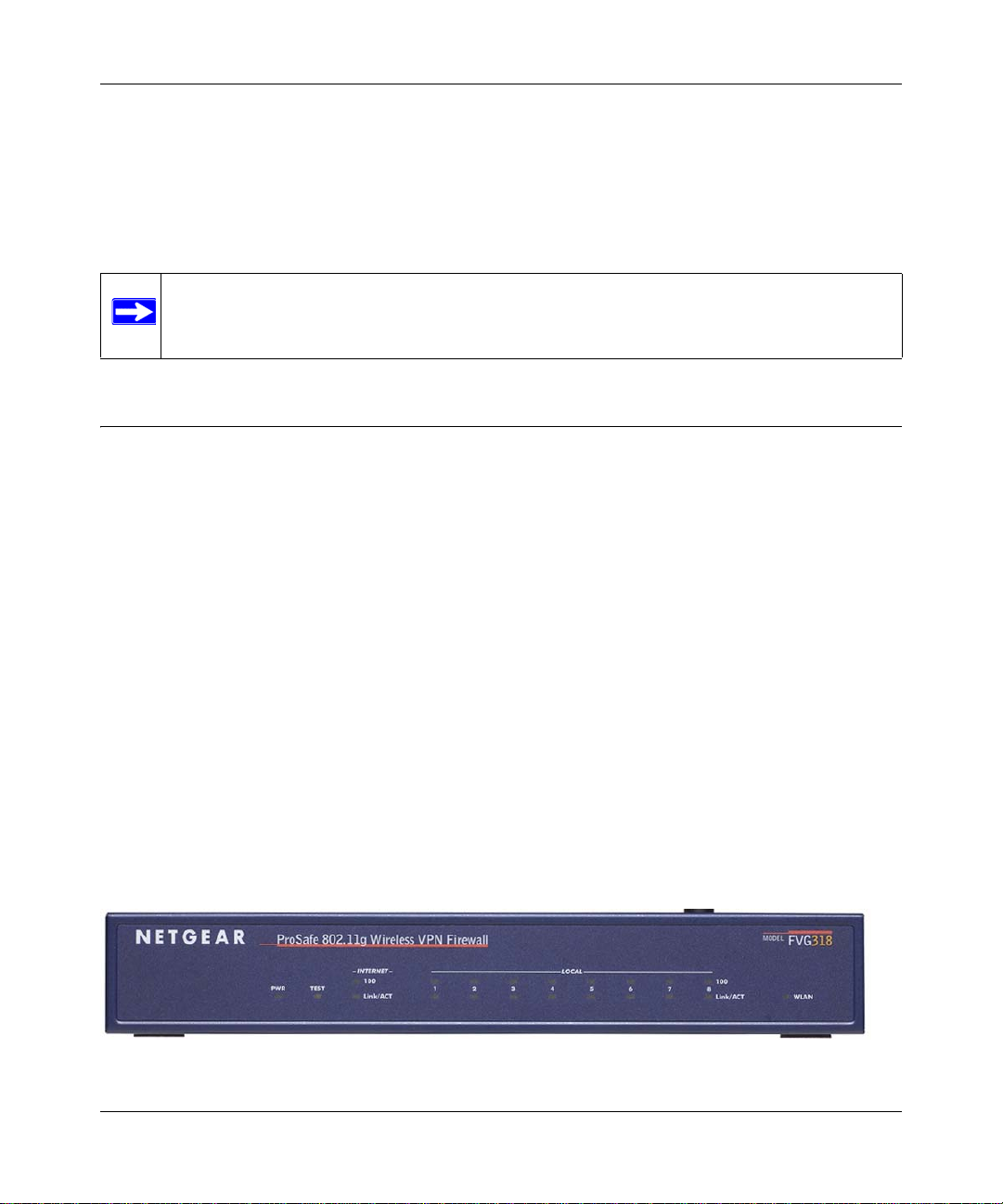
The FVG318 Front Panel
The front panel of the VPN firewall contains the status LEDs described below.
Figure 1-1
Introduction 1-5
v1.0, September 2007
Page 22
ProSafe 802.11g Wireless VPN Firewall FVG318 Reference Manual
You can use some of the LEDs to verify connections. Viewed from left to right, Table 1-1
describes the LEDs on the front panel of the firewall. These LEDs are green when lit.
Table 1-1. LED Descriptions
LED Label Activity Description
PWR On Power is supplied to the firewall.
TEST On
Off
INTERNET
100 (100 Mbps) On
Off
LINK/ACT
(Link/Activity)
LOCAL
100 (100 Mbps) On
LINK/ACT
(Link/Activity)
WLAN On
On
Blinking
Off
On
Blinking
Off
The system is initializing.
The system is ready and running.
The Internet (WAN) port is operating at 100 Mbps.
The Internet (WAN) port is operating at 10 Mbps.
The Internet port has detected a link with an attached device.
Data is being transmitted or received by the Internet port.
The Local port is operating at 100 Mbps.
The Local port is operating at 10 Mbps.
The Local port has detected a link with an attached device.
Data is being transmitted or received by the Local port.
The wireless interface is on.
The wireless interface is off.
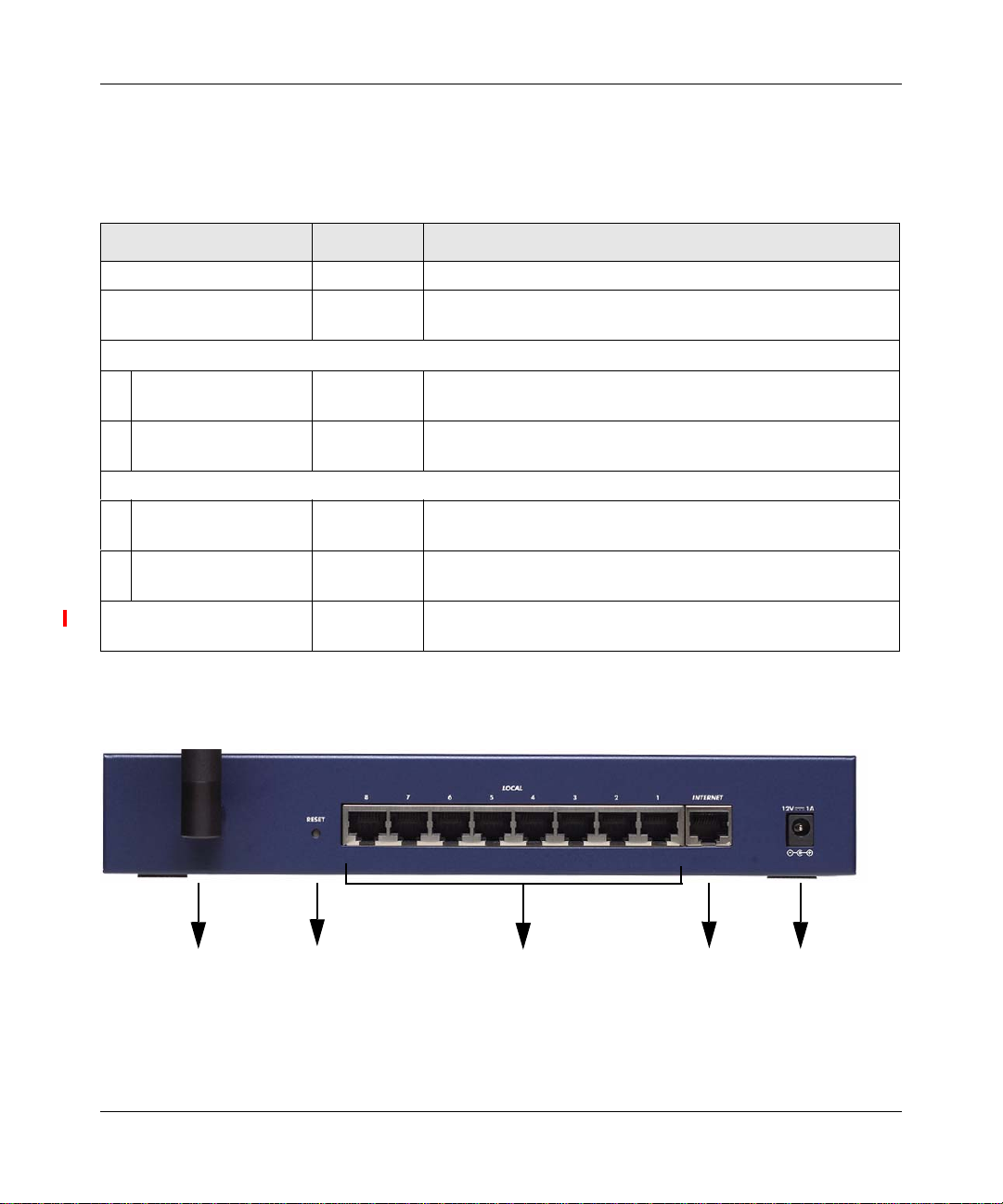
The FVG318 Rear Panel
The rear panel of the VPN firewall contains the port connections listed below.
Antenna
FACTORY
Reset Button
LOCAL
Ports
Port
Figure 1-2
1-6 Introduction
v1.0, September 2007
PowerINTERNET
Page 23

ProSafe 802.11g Wireless VPN Firewall FVG318 Reference Manual
Viewed from left to right, the rear panel contains the following features:
• Detachable wireless antenna
• Factory default reset push button
• Eight Ethernet LAN ports
• Internet Ethernet WAN port for connecting the firewall to a cable or DSL modem
• DC power input
Introduction 1-7
v1.0, September 2007
Page 24

ProSafe 802.11g Wireless VPN Firewall FVG318 Reference Manual
1-8 Introduction
v1.0, September 2007
Page 25

Chapter 2
Connecting the Firewall to the Internet
This chapter describes how to set up the firewall on your LAN, connect to the Internet, perform
basic configuration of your ProSafe 802.11g Wireless VPN Firewall using the Setup Wizard, or
how to manually configure your Internet connection.
Follow these instructions to set up your firewall.
Installing Your FVG318
• For Cable Modem Service: When you set up the VPN firewall router, be sure to use the
computer you first registered with your cable modem service provider.
• For DSL Service: You may need information such as the DSL login name and password in
order to complete the VPN firewall router setup.
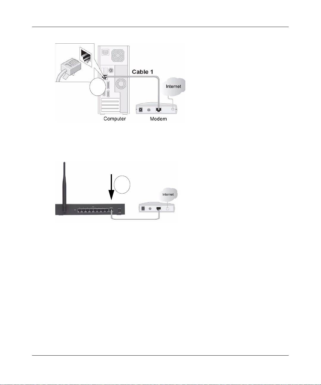
To connec t the FVG318:
1. Connect the VPN firewall router to your computer and modem
a. Turn off and unplug your cable or DSL modem.
b. Turn off your computer
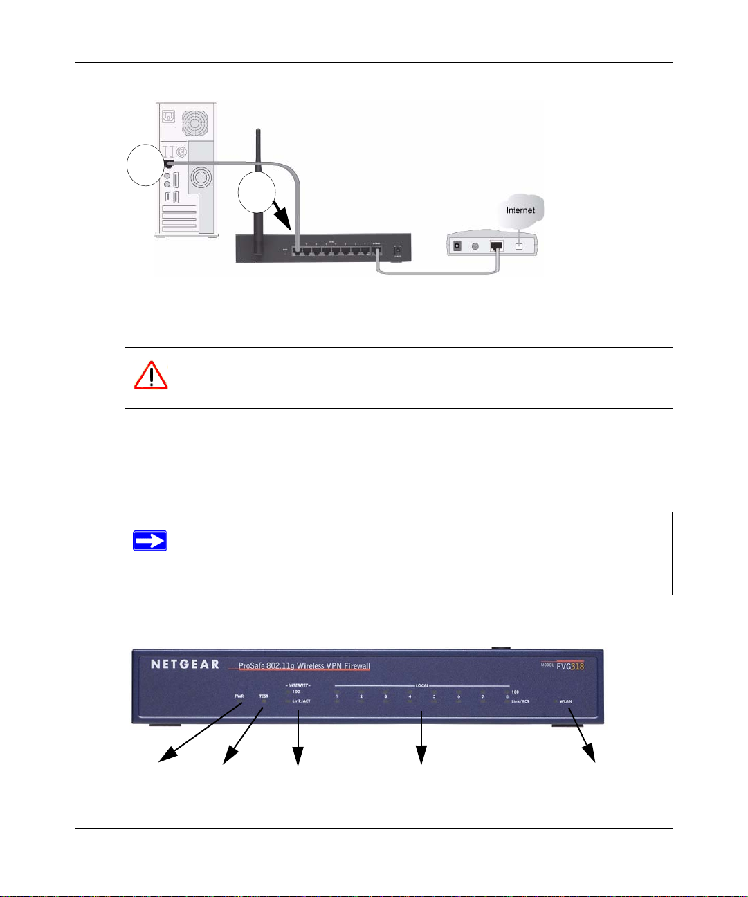
c. At the computer end only, disconnect the Ethernet cable (point A in the illustration) that
connects your computer to the cable or DSL modem.
Connecting the Firewall to the Internet 2-1
v1.0, September 2007
Page 26
ProSafe 802.11g Wireless VPN Firewall FVG318 Reference Manual
A
Figure 2-1
d. Securely insert the Ethernet cable from your modem into the FVG318 Internet port (point
B in the illustration).
B
Figure 2-2
e. Securely insert one end of the NETGEAR cable that came with your FVG318 into a Local
port on the router such as port 4 (point C in the illustration), and the other end into the
Ethernet port of your computer (point D in the illustration).
2-2 Connecting the Firewall to the Internet
v1.0, September 2007
Page 27
ProSafe 802.11g Wireless VPN Firewall FVG318 Reference Manual
D
C
Figure 2-3
2. Restart your network in the correct sequence
Warning: Failure to restart your network in the correct sequence could prevent you
from connecting to the Internet.
a. First, plug in and turn on the cable or DSL modem.Wait about 2 minutes.
b. Now, plug in the power cord to your FVG318 and wait about 30 seconds.
c. Last, turn on your computer.
Note: For DSL customers, if ISP-provided software logs you in to the Internet,
do not run that software. You may need to go to the Internet Explorer®
Tools menu, Internet Options, Connections tab page where you can select
the “Never dial a connection” radio button and click Apply.
d. Check the status lights and verify the following:
Power
Figure 2-4
Connecting the Firewall to the Internet 2-3
Test
Internet Port
Local Ports (8)
Wireless
v1.0, September 2007
Page 28
ProSafe 802.11g Wireless VPN Firewall FVG318 Reference Manual
• Power: The power light should be lit. If after 2 minutes the power light turns solid amber,
see the Troubleshooting Tips in this guide.
• Test: The test light blinks when the FVG318 is first turned on. If after 2 minutes it is still
on, see the Troubleshooting Tips in this guide.
• Internet: The Internet light on the FVG318 should be lit. If not, make sure the Ethernet
cable is securely attached to the VPN firewall router Internet port and the powered on
modem.
• Wireless: The WLAN light should be lit. If the Wireless light is not lit, see the
Troubleshooting Tips in this guide.
• LOCAL: A LOCAL light should be lit.
Configuring the FVG318 for Internet Access with Auto Detect
To connec t to the firewall, your computer needs to be configured to obtain an IP address
automatically via DHCP, which is usually the case for most computers. However, if you need
instructions on how to configure your TCP/IP settings to obtain an IP address automatically, see
“Internet Networking and TCP/IP Processing” at Appendix B, “Related Documents.
Before you begin, be sure you have the configuration parameters from your ISP hand y.
To log in the router:
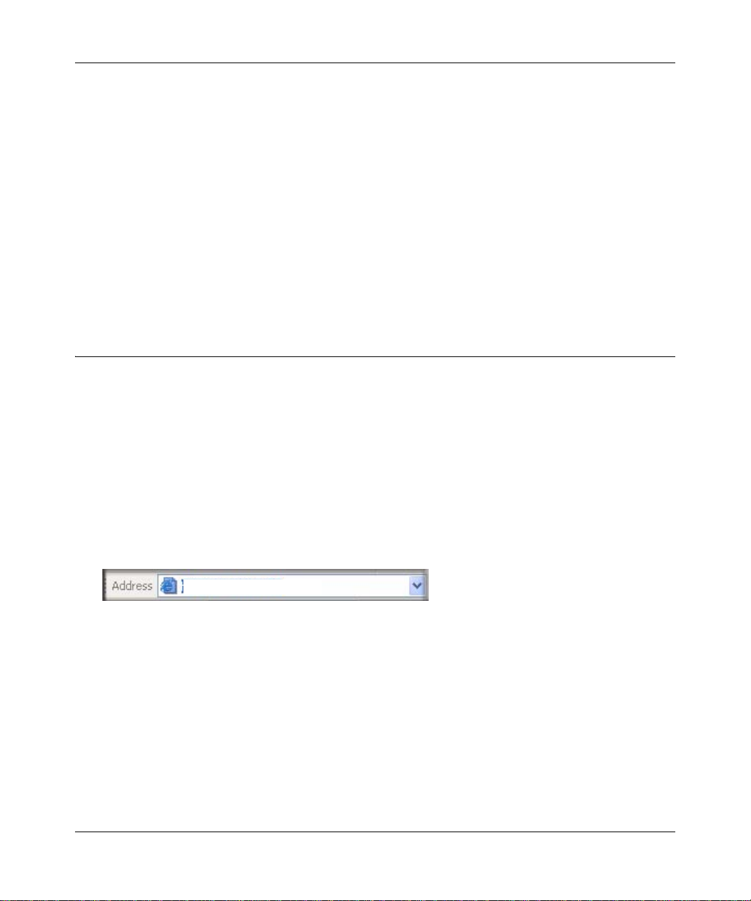
1. 0pen a browser such as Internet Explorer, Netscape Navigator or Firefox and enter the default
IP address of the router in the browser address field: http://192.168.0.1.
http://192.168.0.1
Figure 2-5
2-4 Connecting the Firewall to the Internet
v1.0, September 2007
Page 29
ProSafe 802.11g Wireless VPN Firewall FVG318 Reference Manual
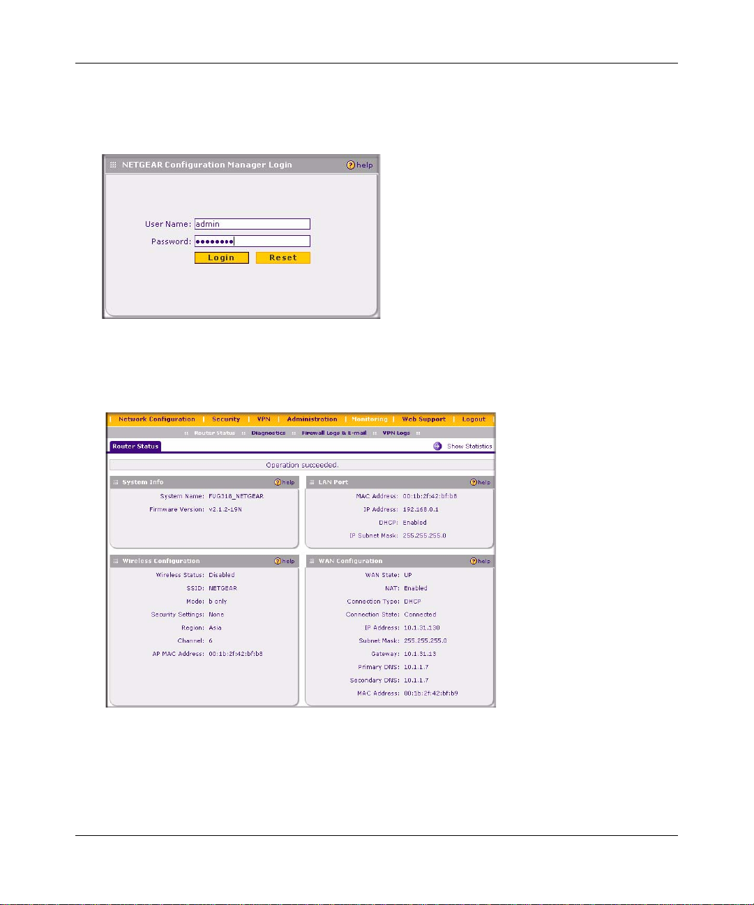
2. When prompted, enter admin for the firewall User Name and password for the firewall
Password. Both fields are case-sensitive. (For security reasons, the firewall has its own User
Name and Password.)
Figure 2-6
3. Click Login. You will be connected to the firewall Router Status screen which will give you
status of your router configuration and current firmware version.
Figure 2-7
Connecting the Firewall to the Internet 2-5
v1.0, September 2007
Page 30
ProSafe 802.11g Wireless VPN Firewall FVG318 Reference Manual
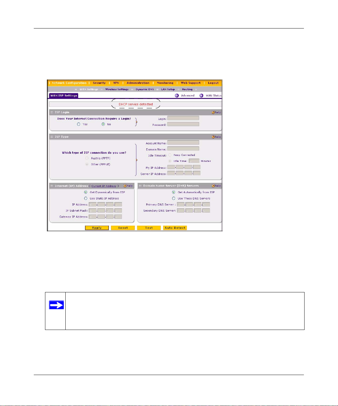
4. Select Network Configuration. The WAN ISP Settings screen will display. Click Auto Detect
at the bottom of the WAN ISP Settings screen. The router will automatically attempt to detect
your connection type. A message will display indicating if the service connection was
detected.
Figure 2-8
If you know your ISP connection type or if want to bypass the auto configuration, you can
manually configure the router settings on the WAN ISP screen. See the
“Manually
Configuring your Internet Connection” on page 2-7 to connect your router manually.
5. Click Test to verify that the Internet connection is active.
Note: You might want to enable remote management at this time so that you can log
in remotely in the future to manage the gateway. See
“Enabling Remote
Management Access” on page 8-8 for more information. Remote management
enable is cleared with a factory default reset.
2-6 Connecting the Firewall to the Internet
v1.0, September 2007
Page 31

ProSafe 802.11g Wireless VPN Firewall FVG318 Reference Manual
Note: When you enable remote management, we strongly advise that you change
your password. See
“Changing the Administrator Password” on page 7-6 for
the procedure on how to do this.
Manually Configuring your Internet Connection
Unless your ISP assigns your configuration automatically via DHCP, you will need the
configuration parameters from your ISP. For example, if your router detected a PPPoE or PPPoA
service, you must provide a Login sequence in order to obtain an Internet connection from your
ISP. If your ISP requires a Static IP address, then you must provide the fixed addresses for Static
IP. The types of data you will need are highlighted in Table 2-1 by connection method, and
explained in more detail below.
The information required by each of the connection types is described in the following table.
Ta ble 2-1. Internet Service Connections
Connection Method Data Required
PPPoE Login (Username, Password).
PPPoA Login (Username, Password).
DHCP (Dynamic IP) No data is required.
Static (Fixed) IP Internet IP address, Subnet Mask and Gateway IP Address supplied by
your ISP; and the Router’s DNS Address (also supplied by your ISP).
IPoA Internet IP Address and Subnet Mask; Gateway IP Address
To configure your Internet connection:
1. Enter your ISP Login information. Select the Does Your Internet Connection require a
Login? option based on the type of account your have with your ISP. If you need to enter login
information every time you connect to the Internet, select Yes. Otherwise, select No.
If your connection is PPTP or PPPoE, then you need to login. Choose Yes and enter:
– Login. This is often the name that you use in your e-mail address (for example, if your
main mail account is jdoe@aol.com, enter jdoe).
Note: Some ISPs (for example, Earthlink) require that you use your full e-mail
address when you log in.
Connecting the Firewall to the Internet 2-7
v1.0, September 2007
Page 32

ProSafe 802.11g Wireless VPN Firewall FVG318 Reference Manual
– Password. Enter the password you use to log in to your ISP.
• Enter your ISP Type information:
– Austria (PPTP): If your ISP is Austria T elecom or any other ISP that uses PPTP to log in,
fill in the following fields:
• Account Name (also known as Host Name or System Name): Valid account name for
the PPTP connection. This is usually your email “ID” assigned by your ISP, the name
before the “@” symbol in your email address. Some ISPs require that you enter your
full email address here.
• Domain Name: Domain name or workgroup name assigned by your ISP, or your ISPs
domain name (optional).
• Idle Timeout: Select Keep Connected, to Keep the Connection Always On. T o logout
after the connection is idle for a period of time, select Idle Time and enter the number
of minutes to wait before disconnecting in the Timeout field. This is useful if your ISP
charges you based on the amount of time you have logged in.
• My IP Address: IP address assigned by the ISP to make a connection with the ISP
server.
• Server IP Address: IP address of the PPTP server.
– Other (PPPoE): If you have installed log in software such as WinPoET or Enternet, then
your connection type is PPPoE. Select this option and configure the following fields:
• Account Name: Valid account name for the PPPoE connection
• Domain Name: Name of your ISPs domain or your domain name if your ISP has
assigned one (optional).
• Idle Timeout: Select Keep Connected, to keep the connection always on. To logout
after the connection is idle for a period of time, select Idle Time and enter the number
of minutes to wait before disconnecting, in the Timeout field.
2. Enter your Internet (IP) Address.
– Select the Get dynamically from ISP radio box if you have not been assigned any static
IP address. The ISP will automatically assign an IP address to the router using DHCP
network protocol.
– If your ISP has assigned a fixed (static) IP address, select Use Static IP Address and fill
in the following fields:
• IP Address: Static IP address assigned to you. This will identify the router to your
ISP.
2-8 Connecting the Firewall to the Internet
v1.0, September 2007
Page 33

ProSafe 802.11g Wireless VPN Firewall FVG318 Reference Manual
• IP Subnet Mask: This is usually provided by the ISP or your network administrator.
• Gateway IP Address: IP address of your ISP’s gateway. This is usually provided by
the ISP or your network administrator.
3. Select your Domain Name Servers (DNS). Domain name servers (DNS) convert Internet
names such as www.google.com, www.netgear.com, etc. to Internet addresses called IP
addresses.
– Select the Get Automatically from ISP radio box if you have not been assigned a static
DNS IP address.
– If the Use these DNS Servers radio box is selected, enter valid DNS server IP addresses
in the Primary DNS Server and Secondary DNS Server fields.
4. Click Apply to save your settings. Click Test to verify that the connection is active.
Note: At this point in the configuration process, you should now be connected to the
Internet.
Configuring Dynamic DNS (If Needed)
Note: If your ISP assigns a private WAN IP address such as 192.168.x.x or 10.x.x.x, the
dynamic DNS service will not work because private addresses will not be routed
on the Internet.
If your network has a permanently assigned (static or fixed) IP address, you can register a domain
name and have that name linked with your IP address by public Domain Name Servers (DNS).
However, if your Internet account uses a dynamically assigned IP address, you will not know in
advance what your IP address will be, and the address can change frequently. In this case, you can
use a commercial dynamic DNS service, which allows you to register an extension to its domain,
and resolves DNS requests for the resulting FQDN to your frequently-changing IP address.
For rollover mode, you will need a fully qualified domain name (FQDN) to implement features
such as exposed hosts and virtual private networks regardless of whether you have a fixed or
dynamic IP address.
Connecting the Firewall to the Internet 2-9
v1.0, September 2007
Page 34

ProSafe 802.11g Wireless VPN Firewall FVG318 Reference Manual
The gateway contains a client that can connec t to a dynamic DNS service provider. To use this
feature, you must select a service provider and obtain an account with them. After you have
configured your account information in the gateway, whenever your ISP-assigned IP address
changes, your gateway will automatically contact your dynamic DNS service provider, log in to
your account, and register your new IP address.
To configure Dynamic DNS:
1. Select Network Configuration > Dynamic DNS. The Dynamic DNS screen will display
with the default Dynamic DNS selected as None.
Figure 2-9
2. Each DNS service provider—Dynamic DNS, DNS TZO or DNS Oray—requires its own
parameters (
Figure 2-9). Select the tab for the DNS service provider you want to use and then
select the Yes radio box. Click Apply.
3. Access the W eb site of the Dynamic DNS service provider you have chosen and register for an
account (for example, for dyndns.org, go to http://www.dyndns.org).
4. Complete entering the Dynamic DNS screen for the service you have chosen:
a. Select the Use a dynamic DNS service check box of the name of your dynamic DNS
Service Provider.
b. Enter the entire FQDN that your dynamic DNS service provider gave you,
(for example, myName.dyndns.org).
c. Enter the User Name and Password (or key) for logging into your dyna mic DNS account.
d. If your dynamic DNS provider allows the use of wild cards in resolving your URL, you
may select the Use wild cards check box to activate this feature.
For example, the wildcard feature will cause *.yourhost.dyndns.org to be aliased to
the same IP address as
2-10 Connecting the Firewall to the Internet
yourhost.dyndns.org
v1.0, September 2007
Page 35

ProSafe 802.11g Wireless VPN Firewall FVG318 Reference Manual
5. Click Apply to save your configuration.
Configuring Your Time Zone
The VPN firewall uses the Network Time Protocol (NTP) to obtain the current time and date from
one of several Network Time Servers on the Internet. In order to localize the time for your log
entries, you must specify your Time Zone.
Figure 2-10
To specify your time zone:
1. Select Administration > Time Zone from the menu. The Time Zone screen will display.
2. From the Date/Time pull-down menu, select your local time zone. This setting will be used
for the blocking schedule and for time-stamping log entries.
3. Automatically Adjust for Daylight Savings Time. Check this box for enable daylight
savings time.
Note: If your region uses Daylight Savings Time, you must manually select Adjust
for Daylight Savings Time on the first day of Daylight Savings Time, and
deselect it at the end. Enabling Daylight Savings Time will add one hour to the
standard time.
4. Select an NTP Server.
•The Use Default NTP Servers is selected by default. If this is enabled, then the RTC
(Real-Time Clock) is updated regularly by contacting a NETGEAR NTP Server on the
Internet.
Connecting the Firewall to the Internet 2-11
v1.0, September 2007
Page 36

ProSafe 802.11g Wireless VPN Firewall FVG318 Reference Manual
• Select the Use Custom NTP Servers if you prefer to use a particular NTP server.
– Enter the name or IP address of an NTP Server in the Server 1 Name/IP Address
field.
– If required, you can also enter the address of another NTP server in the Server 2
Name/IP Address field.
If you select this option and leave either the Server 1 or Server 2 fields empty, then they
will be set to the default NETGEAR NTP servers (time-a.netgear.com, timeb.netgear.com, etc.).
5. Click Apply to save your settings.
Troubleshooting Tips
Here are some tips for correcting simple problems you may have.
Be sure to restart your network in the correct sequence.
Always follow this sequence: 1) Unplug and turn off the mo dem, FVG318 , an d co mp uter; 2 ) p lug
in and turn on the modem, wait two minutes; 3) plug in the FVG318 and wait 30 seconds; 4) turn
on the computer.
Make sure the Ethernet cables are securely plugged in.
• For each powered on computer connected to the VPN firewall router with a securely plugged
in Ethernet cable, the corresponding VPN firewall router LAN port status light will be lit. The
label on the bottom of the VPN firewall router identifies the number of each LAN port.
• The Internet port status light on the VPN firewall router will be lit if the Ethernet cable from
the FVG318 to the modem is plugged in securely and the modem and VPN firewall router are
turned on.
Make sure the computer & router wireless settings match exactly.
The Wireless Network Name (SSID) and security settings (WEP/WPA, MAC access control list)
of the FVG318 and wireless computer must match exactly.
Make sure the network settings of the computer are correct.
• LAN and wirelessly connected computers must be configured to obtain an IP address
automatically via DHCP.
2-12 Connecting the Firewall to the Internet
v1.0, September 2007
Page 37

ProSafe 802.11g Wireless VPN Firewall FVG318 Reference Manual
• Some cable modem ISPs require you to use the MAC address of the computer registered on
the account. If so, in the Router MAC Address section of the Basic Settings menu, select, “Use
this Computer’s MAC Address.” The router will then capture and use the MAC address of the
computer that you are now using. You must be u sing the computer that is registered with the
ISP. Click Apply to save your settings. Restart the network in the correct sequence.
Check the router status lights to verify correct router operation.
• If the Power light does not turn solid green within 2 minutes after turning the router on, reset
the router according to the instructions in the Reference Manual on the CD.
• If the Wireless light does not come on, verify that the wireless feature is turned on according to
the instructions in the Reference Manual on the CD.
Tips for Accessing the VPN firewall
The table below describes how you access the VPN firewall router, depending on the state of the
VPN firewall router.
Table 2-2. Accessing the firewall router
Firewall Stat e Access Options Description
Factory Default
Note: The VPN
firewall router is
supplied in the
factory default state.
Also, the factory
default state is
restored when you
use the factory reset
button. See “To
backup and restore
your configuration:”
on page 7-5 for
more information on
this feature.
Automatic Access via
the Smart Wizard
Configuration
Assistant
Manually enter a URL
to bypass the Smart
Wizard Configuration
Assistant
Any time a browser is opened on any computer connected to
the VPN firewall router, the VPN firewall router will
automatically connect to that browser and display the
Configuration Assistant welcome page.
There is no need to enter the VPN firewall router URL in the
browser, or provide the login user name and password.
You can bypass the Smart Wizard Configuration Assistant
feature by typing
http://192.168.0.1/basicsetting.htm
in the browser address bar and pressing Enter. You will not
be prompted for a user name or password.
This will enable you to manually configure the VPN firewall
router even when it is in the factory default state. When
manually configuring the firewall, you must complete the
configuration by clicking Apply when you finish entering your
settings. If you do not do so, a browser on any PC connected
to the firewall will automatically display the firewall
Configuration Assistant welcome page rather than the
browser’s home page.
Connecting the Firewall to the Internet 2-13
v1.0, September 2007
Page 38

ProSafe 802.11g Wireless VPN Firewall FVG318 Reference Manual
Table 2-2. Accessing the firewall router (continued)
Firewall Stat e Access Options Description
Configuration
Settings Have Been
Applied
Enter the standard
URL to access the
VPN firewall router
Enter the IP address
of the VPN firewall
router
Connect to the VPN firewall router by typing the default router
IP address in the address field of your browser, then press
Enter:
http://192.168.0.1
The VPN firewall router will prompt you to enter the user
name of admin and the password. The default password is
password.
Connect to the VPN firewall router by typing the IP address of
the VPN firewall router in the address field of your browser,
then press Enter. 192.168.0.1 is the default IP address of the
VPN firewall router. The VPN firewall router will prompt you
to enter the user name of admin and the password. The
default password is password.
2-14 Connecting the Firewall to the Internet
v1.0, September 2007
Page 39

Chapter 3
Configuring Wireless Connectivity
This chapter describes how to configure the wireless features of your FVG318 VPN firewall.
Observing Performance, Placement, and Range Guidelines
In planning your wireless network, you should consider the level of security required. You should
also select the physical placement of your FVG318 in order to maximize the network speed. For
further information on wireless networking, refer to in “Wireless Communications” in Appendix
B.
Note: Failure to follow these guidelines can result in significant performance degradation
or inability to wirelessly connect to the VPN firewall router. For complete range
and performance specifications, please see “Default Settings and Technical
Specifications” in Appendix A.”
The operating distance or range of your wireless connection can vary significantly bas ed on the
physical placement of the VPN firewall. The latency, data throughput performance, and notebook
power consumption also vary depending on your configuration choices. For best results, place
your VPN firewall router:
• Near the center of the area in which your PCs will operate.
• In an elevated location, such as a high shelf where the wirelessly connected PCs have line-ofsight access (even if through walls). The best location is elevated, such as wall mounted or on
the top of a cubicle, and at the center of your wireless coverage area for all the mobile devices.
• Away from sources of interference, such as PCs, microwaves, and 2.4 GHz cordless phones.
• Away from large metal surfaces.
Be aware that the time it takes to establish a wireless connection can vary depending on both your
security settings and placement. WEP connections can take slightly longer to establish. Also, WEP
encryption can consume more battery power on a notebook computer.
Configuring Wireless Connectivity 3-1
v1.0, September 2007
Page 40

ProSafe 802.11g Wireless VPN Firewall FVG318 Reference Manual
Implementing Appropriate Wireless Security
Unlike wired network data, your wireless data transmissions can extend beyond your walls and
can be received by anyone with a compatible adapter. For this reason, use the security features of
your wireless equipment. The VPN firewall provides highly effective security features which are
covered in detail in this chapter.
FVG318
Figure 3-1
Note: Indoors, computers can connect to wireless networks at ranges of 300 feet or more.
Such distances allow others outside of your area to access your network.
There are several ways you can enhance the security of your wireless network:
• Restrict Access Based on MAC Address. You can allow only trusted PCs to connect so that
unknown PCs cannot wirelessly connect to the FVG318. Restricting access by MAC address
adds an obstacle against unwanted access to your network, but the data broadcast over the
wireless link is fully exposed.
• Turn Off the Broadcast of the Wireless Network Name SSID. If you disable broadcast of
the SSID, only devices that have the correct SSID can connect. This nullifies wireless network
“discovery” feature of some products, such as Windows XP, but the data is still exposed.
• WEP. Wired Equivalent Privacy (WEP) data encryption provides data security. WEP Shared
Key authentication and WEP data encryption will block all but the most determined
eavesdropper.
3-2 Configuring Wireless Connectivity
v1.0, September 2007
Page 41

ProSafe 802.11g Wireless VPN Firewall FVG318 Reference Manual
• Wi-Fi Protected Access (WPA and WPA2). The very strong authentication along with
dynamic per frame rekeying of WPA and WPA2 make it virtually impossible to compromise.
Because this is a new standard, wireless device driver and software availability may be
limited.
– WPA with PSK (Wi-Fi Protected Access Pre-Shared Key). WPA-PSK uses TKIP
standard encryption.
– WPA2 with PSK. WPA2 is a later version of WPA. Only select this if all clients support
WPA2. If selected, you must use AES encryption, and enter the WPA passphrase
(Network key).
– WPA-PSK and WPA2-PSK. This selection allows clients to use either WPA (with TKIP
encryption) or WPA2 (with AES encryption). If selected, encryption must be TKIP +
AES.
– WPA with Radius. This version of WPA requires the use of a Radius server for
authentication. Each user (Wireless Client) must have a “user” login on the Radius
Server—normally done via a digital certificate. Also, this device must have a “client”
login on the Radius server. Data transmissions are encrypted using a key which is
automatically generated.
– WPA2 with RADIUS. WPA2 is a later version of WPA. Only select this if all clients
support WPA2. If selected, you must use AES encryption, and configure the RADIUS
Server Settings. Each user (Wireless Client) must have a “user” login on the Radius
Server—normally done via a digital certificate. Also, this device must have a “client”
login on the RADIUS server. Data transmissions are encrypted using a key which is
automatically generated.
– WPA and WPA2 with RADIUS. This selection allows clients to use either WPA (with
AES encryption) or WPA2 (with TKIP encryption). If selected, encryption must be
TKIP+AES. You must also configure the RADIUS Server Settings
Understanding Wireless Settings
To configure the wireless settings of your FVG318:
1. Select Network Configuration > Wireless Settings from the main menu. The Wireless Settings
screen will display.
Configuring Wireless Connectivity 3-3
v1.0, September 2007
Page 42

ProSafe 802.11g Wireless VPN Firewall FVG318 Reference Manual
Figure 3-2
Note: The 802.11b and 802.11g wireless networking protocols are configured in
exactly the same fashion. The FVG318 will automatically adjust to the 802.11g
or 802.11b protocol as the device requires without compromising the speed of
the other devices.
• Wireless Network. The station name of the FVG318.
– Wireless Network Name (SSID). The SSID is also known as the wireless network name.
Enter a value of up to 32 alphanumeric characters. In a setting where there is more than
one wireless network, different wireless network names provide a means for separating the
traffic. Any device you want to participate in the 802.11b/g wireless network will need to
use this SSID for that network. The FVG318 default SSID is: NETGEAR.
3-4 Configuring Wireless Connectivity
v1.0, September 2007
Page 43

ProSafe 802.11g Wireless VPN Firewall FVG318 Reference Manual
– Region. This field identifies the region where the FVG318 can be used. It may not be legal
to operate the wireless features of the VPN firewall router in a region other than one of
those identified in this field. Unless you select a region, you will only be able to use
Channel 11.
– Channel. This field determines which operating frequency will be used. It should not be
necessary to change the wireless channel unless you notice interference problems with
another nearby access point. For more information on the wireless channel frequencies,
please refer to
“Wireless Communications” in Appendix B.
– Mode. Select the desired wireless mode. The options are:
• g & b - Both 802.11g and 802.11b wireless stations can be used.
• g only - Only 802.11g wireless stations can be used.
• b only - All 802.11b wireless stations can be used. 802.11g wireless stations can still
be used if they can operate in 802.11b mode.
The default is “g & b” which allows both 802.11g and 802.11b wireless stations to access
this device.
• Wireless Access Point
– Enable Wireless Access Point. Enables the wireless radio. When disabled, there are no
wireless communications through the FVG318.
– Allow Broadcast of Name (SSID). The default setting is to enable SSID broadcast. If you
disable broadcast of the SSID, only devices that have the correct SSID can connect.
Disabling SSID broadcast somewhat hampers the wireless network “discovery” feature of
some products.
• Wireless Card Access List
Lets you restrict wireless connections according to a list of Trusted PCs MAC addresses.
When the Trusted PCs Only radio button is selected, the FVG318 checks the MAC address of
the wireless station and only allows connections to PCs identified on the trusted PCs list.
T o restrict access based on MAC addresses, click the Set up Access List button and update the
MAC access control list.
• Security Options
– Disable: No data encryption is used.
– WEP (Wired Equivalent Privacy): Use WEP 64 or 128 bit data encryption.
– WPA-PSK (Wi-Fi Protected Access Pre-Shared Key): Use TKIP standard encryption
Configuring Wireless Connectivity 3-5
v1.0, September 2007
Page 44

ProSafe 802.11g Wireless VPN Firewall FVG318 Reference Manual
– WPA2-PSK: WPA2 is a later version of WPA. Only select this if all clients support
WPA2. If selected, you must use AES encryption
– WPA-PSK and WPA2-PSK: This selection allows clients to use either WPA (with TKIP
encryption) or WPA2 (with AES encryption). If selected, encryption must be TKIP +
AES.
– WPA with Radius: This version of WPA requires the use of a Radius server for
authentication. Each user (Wireless Client) must have a “user” login on the Radius
Server—normally done via a digital certificate. Also, this device must have a “client”
login on the Radius server. Data transmissions are encrypted using a key which is
automatically generated.
– WPA2 with Radius: WPA2 is a later version of WPA. Only select this if all clients
support WP A2. If selected, you must use AES encryption, and configure the Radius Server
Settings.
– WPA and WPA2 with Radius: This selection allows clients to use either WP A (with AES
encryption) or WPA2 (with TKIP encryption). If selected, encryption must be TKIP +
AES. If selected, you must configure the Radius Server Settings.
3-6 Configuring Wireless Connectivity
v1.0, September 2007
Page 45

ProSafe 802.11g Wireless VPN Firewall FVG318 Reference Manual
Security Check List for SSID and WEP Settings
For a new wireless network, print or copy this form and fill in the configuration parameters. For an
existing wireless network, the person who set up or is responsible for the network will be able to
provide this information. Be sure to set the Regulatory Domain correctly as the first step.
• SSID: The Service Set Identification (SSID) identifies the wireless local area network.
Wireless is the default FVG318 SSID. However, you may customize it by using up to 32
alphanumeric characters. Write your customized SSID on the line below.
Note: The SSID in the VPN firewall router is the SSID you configure in the wireless adapter
card. All wireless nodes in the same network must be configured with the same SSID:
• Authentication
Circle one: Open System or Shared Key. Choose “Shared Key” for more security.
Note: If you select shared key, the other devices in the network will not connect unless they
are set to Shared Key as well and have the same keys in the same positions as those in the
FVG318.
• WEP Encryption Keys
For all four 802.11b keys, choose the Key Size. Circle one: 64 or 128 bits
Key 1: ___________________________________
Key 2: ___________________________________
Key 3: ___________________________________
Key 4: ___________________________________
• WPA-PSK or WPA2-PSK (Pre-Shared Key)
Record the WPA-PSK or WPA2-PSK key:
Key: ___________________________________
• WPA or WPA2 RADIUS Settings
For WPA or WPA2, record the following RADIUS settings:
Server Name/IP Address: Primary _________________ Secondary __________________
Port: ___________________________________
Shared Key: ___________________________________
Use the procedures described in the following sections to configure the FVG318. Store this
information in a safe place.
Configuring Wireless Connectivity 3-7
v1.0, September 2007
Page 46

ProSafe 802.11g Wireless VPN Firewall FVG318 Reference Manual
Setting Up and Testing Basic Wireless Connectivity
Follow the instructions below to set up and test basic wireless connectivity. Once you have
established basic wireless connectivity , you can enable security settings appropriate to your needs.
1. Log in using the default LAN address of http://192.168.0.1 with the default user name of
admin and default password of password, or using whatever LAN address and password you
have set up.
2. Select Network Configuration > Wireless Settings to display the Wireless Settings screen.
Figure 3-3
3. Set the Regulatory Domain correctly.
4. Choose a suitable descriptive name for the wireless network name (SSID). In the SSID box,
enter a value of up to 32 alphanumeric characters. The default SSID is NETGEAR
.
Note: The characters are case sensitive. An access point always functions in
infrastructure mode. The SSID for any wireless device communicating with
the access point must match the SSID configured in the ProSafe 802.11g
Wireless VPN Firewall. If they do not match, you will not get a wireless
connection to the FVG318.
5. Set the Channel.
It should not be necessary to change the wireless channel unless you notice interference
problems with another nearby wireless router or access point. Select a channel that is not being
used by any other wireless networks within several hundred feet of your VPN firewall router.
For more information on the wireless channel frequencies please refer to “Wireless Channels”
in
“Wireless Communications” in Appendix B.
6. Depending on the types of wireless adapters you have in your computers, choose from the
Mode drop-down list.
3-8 Configuring Wireless Connectivity
v1.0, September 2007
Page 47

ProSafe 802.11g Wireless VPN Firewall FVG318 Reference Manual
7. For initial configuration and test, leave the Wireless Card Access List set to “All Wireless
Stations” and the Encryption Strength set to “Disable.”
8. Click Apply to save your changes.
Note: If you are configuring the FVG318 from a wireless computer and you change
the VPN firewall router’s SSID, channel, or security settings, you will lose
your wireless connection when you click on Apply. You must then change the
wireless settings of your computer to match the FVG318’s new settings.
9. Configure and test your PCs for wireless connectivity.
Program the wireless adapter of your PCs to have the same SSID that you configured in the
FVG318. Check that they have a wireless link and are able to obtain an IP address by DHCP
from the VPN firewall router.
Once your PCs have basic wireless connectivity to the VPN firewall router, then you can configure
the advanced options and wireless security functions.
Restricting Wireless Access by MAC Address
To restrict access based on MAC addresses, follow these steps:
1. Log in at the default LAN address of http://192.168.0.1 with the default user name of admin
and default password of password.
2. Select Network Configuration > Wireless Settings and click the Setup Access List link. The
Access Control List screen will display.
Figure 3-4
Configuring Wireless Connectivity 3-9
v1.0, September 2007
Page 48

ProSafe 802.11g Wireless VPN Firewall FVG318 Reference Manual
3. Check the Yes radio box to enable MAC filtering and turn on the Access Control List. Then
click Apply. An “Operation Succeed” message will display. Only Trusted Wireless Stations
will be able to connect to the VPN firewall router.
4. You can add trusted devices by selecting a device from the list of available wireless cards the
FVG318 has discovered in your area, or you can manually enter the MAC address.
• Add a wireless station manually be entering the device MAC Address in the Add New
Trusted Station Manually field and clicking Add. The station will be added to the
Trusted Wireless Stations list (if ACL Enable has been enabled).
• Click the Available Wireless Stations tab to view the list of available wireless stations
within range of this VPN firewall router. To add a wireless station to the ACL, highlight
its MAC address and click Add to Trusted List.
Note: When configuring the FVG318 from a wireless computer whose MAC
address is not in the access control list, if you select Turn Access Control
On, you will lose your wireless connection when you click Apply. Yo u
must then access the VPN firewall router from a wired computer or from a
wireless computer which is on the access control list to make any further
changes.
Now, only devices on this list will be allowed to wirelessly connect to the FVG318.
To remove a MAC address from the table, click to select it, then click Delete.
Configuring WEP Security Settings
Note: When changing the wireless settings from a wireless computer, you will lose your
wireless connection when you click Apply. You must then either configure your
wireless adapter to match the new wireless settings or access the VPN firewall
router from a wired computer to make any further changes.
To configure WEP data encryption, follow these steps:
1. Log in at the default LAN address of http://192.168.0.1 with the default user name of admin
and default password of password, or using whatever LAN address and password you set up.
2. Select Network Configuration > Wireless Settings. The Wireless Settings screen will display.
3-10 Configuring Wireless Connectivity
v1.0, September 2007
Page 49

ProSafe 802.11g Wireless VPN Firewall FVG318 Reference Manual
Figure 3-5
3. In the Wireless Security Type section, select the WEP radio box. The WEP fields section will
be highlighted.
4. Choose the Authentication Type (Automatic, Open System or Shared Key) and Encryption
Strength options. You can manually or automatically program the four data encryption keys.
These values must be identical on all PCs and Access Points in your network.
– Authentication Type: Normally this can be left at the default value of “Automatic.” If set
to “Open System” or “Shared Key”, wireless stations must use the same method.
– Encryption: Select the desired WEP Encryption:
• 64-bit (sometimes called 40-bit) encryption
• 128-bit encryption
– WEP Keys: If using WEP, you can manually or automatically program the four data
encryption keys. These values must be identical on all PCs and Access Points in your
network.
• Automatic Key Generation (Passphrase): Enter a word or group of printable
characters (this phrase is case sensitive) in the Passphrase box and click the “Generate
Keys” button to automatically configure the WEP Key(s).
– If encryption is set to 64 bit, then each of the four key boxes will automatically be
populated with key values.
– If encryption is set to 128 bit, then only the selected WEP key box will automatically
be populated with a key value.
Configuring Wireless Connectivity 3-11
v1.0, September 2007
Page 50

ProSafe 802.11g Wireless VPN Firewall FVG318 Reference Manual
• Manual Entry Mode: Enter ten hexadecimal digits (any combination of 0-9, a-f, or
A-F). These hex values are not case sensitive. Select which of the four keys will be
used and enter the matching WEP key information for your network in the selected
key box.
– For 64 bit WEP: Enter ten hexadecimal digits (any combination of 0-9, A-F).
– For 128 bit WEP: Enter twenty-six hexadecimal digits (any combination of 0-9, A-
F).
Please refer to “Wireless Communications” in Appendix B, “Related Documents” for a full
explanation of each of these options, as defined by the IEEE 802.11b wireless communication
standard.
5. Click Apply to save your settings.
Configuring WPA with RADIUS
Note: Not all wireless adapters support WPA. Furthermore, client software is required on
the client. Windows XP and Windows 2000 with Service Pack 3 do include the
client software that supports WPA. Nevertheless, the wireless a dapter ha rdware
and driver must also support WPA. Consult the product document for your wireless
adapter and WPA client software for instructions on configuring WPA settings.
To configure WPA with RADIUS:
1. Log in at the default LAN address of http://192.168.0.1 with the default user name of admin
and default password of password, or using whatever LAN address and password you have
set up.
2. Select Network Administration > Wireless Settings. The W ireless Settings Screen will display.
3-12 Configuring Wireless Connectivity
v1.0, September 2007
Page 51

ProSafe 802.11g Wireless VPN Firewall FVG318 Reference Manual
Figure 3-6
3. Select the WPA radio box and then select RADIUS from the WPA with: pull-down menu in
the Wireless Security Type section. The RADIUS settings fields in the Radius Server Settings
section will be highlighted.
Note: The Encryption choice will be TKIP by default. For WPA with RADIUS,
TKIP is used.
4. Enter the Radius Server Settings.
• Primary Server Name/IP Address: This field is required. Enter the name or IP address
of the primary Radius Server on your LAN.
• Radius Port: Enter the port number used for connecting to the Radius Server.
• Shared Key: Enter the desired value for the Shared Key. This must match the value used
on the Radius server.
5. Click Apply to save your settings.
Configuring Wireless Connectivity 3-13
v1.0, September 2007
Page 52

ProSafe 802.11g Wireless VPN Firewall FVG318 Reference Manual
Configuring WPA2 with RADIUS
Note: Not all wireless adapters support WPA2. Furthermore, client software is required
on the client. Windows XP and Windows 2000 with Service Pack 3 do include the
client software that supports WPA2. Nevertheless, the wireless adapter hardware
and driver must also support WPA2. Consult the product document for your
wireless adapter and WPA2 client software for instructions on configuring WPA2
settings.
To configure WPA2 with RADIUS:
1. Log in at the default LAN address of http://192.168.0.1 with the default user name of admin
and default password of password, or using whatever LAN address and password you have
set up.
2. Select Network Adminisration > Wireless Settings. The Wireless Settings Screen will display.
Figure 3-7
3. Select the WPA2 radio box and then select RADIUS from the WPA with: pull-down menu in
the Wireless Security Type section. The RADIUS settings fields in the Radius Server Settings
section will be highlighted.
3-14 Configuring Wireless Connectivity
v1.0, September 2007
Page 53

ProSafe 802.11g Wireless VPN Firewall FVG318 Reference Manual
Note: The Encryption choice will be AES by default. For WPA2 with RADIUS,
AES is used.
4. Enter the Radius Server Settings.
• Primary Server Name/IP Address: This field is required. Enter the name or IP address
of the primary Radius Server on your LAN.
• Radius Port: Enter the port number used for connecting to the Radius Server.
• Shared Key: Enter the desired value for the Shared Key. This must match the value used
on the Radius server.
5. Click Apply to save your settings.
Configuring WPA and WPA2 with RADIUS
Note: Not all wireless adapters support WPA and WPA2. Furthermore, client software is
required on the client. Windows XP and Windows 2000 with Service Pack 3 do
include the client software that supports WPA and WPA2. Nevertheless, the
wireless adapter hardware and driver must also support WPA and WPA2. Consult
the product document for your wireless adapter and WPA and WPA2 client
software for instructions on configuring WPA and WPA2 settings.
To configure WPA and WPA2 with RADIUS:
1. Log in at the default LAN address of http://192.168.0.1 with the default user name of admin
and default password of password, or using whatever LAN address and password you have
set up.
2. Select Network Adminisration > Wireless Settings. The Wireless Settings Screen will display.
Configuring Wireless Connectivity 3-15
v1.0, September 2007
Page 54

ProSafe 802.11g Wireless VPN Firewall FVG318 Reference Manual
Figure 3-8
3. Select the WPA and WPA2 radio box and then select RADIUS from the WPA with: pull-
down menu in the Wireless Security Type section. The RADIUS settings fields in the Radius
Server Settings section will be highlighted.
Note: The Encryption choice will be TKIP+AES by default. For WPA/WPA2 with
RADIUS, TKIP+AES is used.
4. Enter the Radius Server Settings.
• Primary Server Name/IP Address: This field is required. Enter the name or IP address
of the primary Radius Server on your LAN.
• Radius Port: Enter the port number used for connecting to the Radius Server.
• Shared Key: Enter the desired value for the Shared Key. This must match the value used
on the Radius server.
5. Click Apply to save your settings.
3-16 Configuring Wireless Connectivity
v1.0, September 2007
Page 55

ProSafe 802.11g Wireless VPN Firewall FVG318 Reference Manual
Configuring WPA-PSK
Note: Not all wireless adapters support WPA. Furthermore, client software is required on
the client. Windows XP and Windows 2000 with Service Pack 3 do include the
client software that supports WPA. Nevertheless, the wireless a dapter ha rdware
and driver must also support WPA. Consult the product document for your wireless
adapter and WPA client software for instructions on configuring WPA settings.
To configure WPA-PSK:
1. Log in at the default LAN address of http://192.168.0.1, with the default user name of admin
and default password of password, or using whatever LAN address and password you have
set up.
2. Select Network Adminisration > Wireless Settings. The Wireless Settings Screen will display.
Figure 3-9
3. Select the WPA radio box and then select PSK from the WPA with: pull-down menu in the
Wireless Security Type section. The PSK settings fields in the PSK Settings section will be
highlighted.
Configuring Wireless Connectivity 3-17
v1.0, September 2007
Page 56

ProSafe 802.11g Wireless VPN Firewall FVG318 Reference Manual
Note: The Encryption choice will be TKIP by default. For WPA+PSK, TKIP is
used.
4. In the PSK Settings section:
• Enter the pre-shared key in the Passphrase field. Enter a word or group of printable
characters in the Passphrase box. The Passphrase must be 8 to 63 characters in length. The
256 Bit key used for encryption is generated from this passphrase.
• Enter a value in the Key Lifetime field. This setting determines how often the encryption
key is changed. Shorter periods provide greater security, but adversely affect performance.
If desired, you can change the default value.
5. Click Apply to save your settings.
Configuring WPA2-PSK
Note: Not all wireless adapters support WPA2. Furthermore, client software is required
on the client. Windows XP and Windows 2000 with Service Pack 3 do include the
client software that supports WPA2. Nevertheless, the wireless adapter hardware
and driver must also support WPA2. Consult the product document for your
wireless adapter and WP2 client software for instructions on configuring WPA2
settings.
To configure WPA2-PSK:
1. Log in at the default LAN address of http://192.168.0.1, with the default user name of admin
and default password of password, or using whatever LAN address and password you have
set up.
2. Select Network Adminisration > Wireless Settings. The Wireless Settings Screen will display.
3-18 Configuring Wireless Connectivity
v1.0, September 2007
Page 57

ProSafe 802.11g Wireless VPN Firewall FVG318 Reference Manual
Figure 3-10
3. Select the WPA2 radio box and then select PSK from the WPA with: pull-down menu in the
Wireless Security Type section. The PSK settings fields in the PSK Settings section will be
highlighted.
Note: The Encryption choice will be AES by default. For WPA2+PSK, AES is used.
4. In the PSK Settings section:
• Enter the pre-shared key in the Passphrase field. Enter a word or group of printable
characters in the Passphrase box. The Passphrase must be 8 to 63 characters in length. The
256 Bit key used for encryption is generated from this passphrase.
• Enter a value in the Key Lifetime field. This setting determines how often the encryption
key is changed. Shorter periods provide greater security, but adversely affect performance.
If desired, you can change the default value.
5. Click Apply to save your settings.
Configuring Wireless Connectivity 3-19
v1.0, September 2007
Page 58

ProSafe 802.11g Wireless VPN Firewall FVG318 Reference Manual
Configuring WPA-PSK and WPA2-PSK
Note: Not all wireless adapters support WPA and WPA2. Furthermore, client software is
required on the client. Windows XP and Windows 2000 with Service Pack 3 do
include the client software that supports WPA and WPA2. Nevertheless, the
wireless adapter hardware and driver must also support WPA and WPA2. Consult
the product document for your wireless adapter and WPA and WPA2 client
software for instructions on configuring WPA and WPA2 settings.
To configure WPA-PSK and WPA2-PSK:
1. Log in at the default LAN address of http://192.168.0.1, with the default user name of admin
and default password of password, or using whatever LAN address and password you have
set up.
2. Select Network Administration > Wireless Settings. The W ireless Settings Screen will display.
Figure 3-11
3. Select the WPA and WPA2 radio box and then select PSK from the WPA with: pull-down
menu in the Wireless Security Type section. The PSK settings fields in the PSK Settings
section will be highlighted.
3-20 Configuring Wireless Connectivity
v1.0, September 2007
Page 59

ProSafe 802.11g Wireless VPN Firewall FVG318 Reference Manual
Note: The Encryption choice will be TKIP+AES by default. For WPA and
WPA2+PSK, TKIP+AES is used.
4. In the PSK Settings section:
• Enter the pre-shared key in the Passphrase field. Enter a word or group of printable
characters in the Passphrase box. The Passphrase must be 8 to 63 characters in length. The
256 Bit key used for encryption is generated from this passphrase.
• Enter a value in the Key Lifetime field. This setting determines how often the encryption
key is changed. Shorter periods provide greater security, but adversely affect performance.
If desired, you can change the default value.
5. Click Apply to save your settings.
Configuring Wireless Connectivity 3-21
v1.0, September 2007
Page 60

ProSafe 802.11g Wireless VPN Firewall FVG318 Reference Manual
3-22 Configuring Wireless Connectivity
v1.0, September 2007
Page 61

Chapter 4
Firewall Protection and Content Filtering
This chapter describes how to use the content filtering features of the ProSafe 802.11g Wireless
VPN Firewall to protect your network. These features can be found by clicking on the Security
heading in the main menu of the browser interface.
Firewall Protection and Content Filtering Overview
The ProSafe 802.11g Wireless VPN Firewall FVG318 provides you with Web content filtering
options, plus browsing activity reporting and instant alerts via e-mail. Parents and network
administrators can establish restricted access policies based on time-of-day, Web addresses and
Web address keywords. You can also block Internet access by applications and services, such as
chat or games.
A firewall is a special category of router that protects one network (the trusted network, such as
your LAN) from another (the untrusted network, such as the Internet), while allowing
communication between the two. A firewall incorporates the functions of a NAT (Network
Address Translation) router, while adding features for dealing with a hacker intrusion or attack,
and for controlling the types of traffic that can flow between the two networks. Unlike simple
Internet sharing NAT routers, a firewall uses a process called stateful packet inspection to protect
your network from attacks and intrusions. NAT performs a very limited stateful inspection in that
it considers whether the incoming packet is in response to an outgoing request, but true stateful
packet inspection goes far beyond NAT.
To configure these features of your firewall, click on the Security > Block Sites heading in the
main menu of the browser interface. The Content Filtering features are described below:
Block Sites
The FVG318 supports content filtering which allows you to block access to certain Internet sites.
Up to 32 words in an Internet sites name (for example, a website URL) can be specified causing
the site to be blocked.
Firewall Protection and Content Filtering 4-1
v1.0, September 2007
Page 62

ProSafe 802.11g Wireless VPN Firewall FVG318 Reference Manual
Certain commonly used web components can also be blocked for increased security. Some of these
components can be used by malicious websites to infect computers that access them. For example:
• Proxy. A proxy server allows computers to route connections to other computers through the
proxy, thus circumventing certain firewall rules. For example, if connections to a specific IP
address are blocked by a firewall rule, the requests can be routed through a proxy that is not
blocked by the rule, rendering the restriction ineffective. Enabling this feature blocks proxy
servers.
• Java. Enabling this feature blocks java applets from being downloaded from pages that
contain them. Java applets are small programs embedded in web pages that enable dynamic
functionality of the page. A malicious applet can be used to compromise or infect computers.
Enabling this setting blocks Java applets from being downloaded.
• Active X. Similar to Java applets, ActiveX controls are installed on Windows computers
running Internet Explorer. A malicious ActiveX control can be used to compromise or infect
computers. Enabling this setting blocks ActiveX applets from being downloaded.
• Cookies. Cookies are used to store session information by websites that usually require login.
However, several websites use cookies to store tracking information and browsing habits.
• Enabling this option filters out cookies from being created by a website.
Note: Many websites require that cookies be accepted in order for the site to be
accessed properly. Blocking cookies may cause many websites to not function
properly.
Figure 4-1
To enable Content Filtering:
1. Select Security > Block Sites from the menu. The Block Sites screen will display.
4-2 Firewall Protection and Content Filtering
v1.0, September 2007
Page 63

ProSafe 802.11g Wireless VPN Firewall FVG318 Reference Manual
2. Check the Yes radio box in the Content Filtering section and click Apply. This will enable
content filtering and allow you to specify Web Components to be blocked.
3. Check the radio box for each Web Component you want to enable; then click Apply. The
selected Web Component options will be blocked.
Once Content Filtering has been enabled you can add Trusted IP Addresses, Blocked Keywords
and Trusted Domains.
Trusted Internet Addresses and T rusted Domains are Internet addresses and sites for which content
filtering maybe bypassed. The Trusted IP Addresses table and the Trusted Domain table list the
currently defined trusted IP addresses and domains.
The domain will appear in the Trusted Domain list. Any number of domain names can be added to
the list. Those names entered in the Trusted Domain list will be bypassed by Keyword filtering.
For example: If yahoo is added to the Blocked Keywords list and www.yahoo.com is added to the
Trusted Domain list, then www.yahoo.com will be allowed but mail.yahoo.com will not allowed.
Figure 4-2
To add a Trusted IP Address or Trusted Domain:
Firewall Protection and Content Filtering 4-3
v1.0, September 2007
Page 64

ProSafe 802.11g Wireless VPN Firewall FVG318 Reference Manual
1. In the appropriate field add the IP Address or Domain Name.
2. Click Add. The IP Address or Domain Name will appear in the appropriate table.
3. Click Edit adjacent to the entry to modify or change the selected IP Address or Domain Name.
An Edit screen will display. When you have completed your changes, click Apply. The change
will appear in the appropriate table.
To delete Trusted IP Addresses or Trusted Domain Names:
• Click Select All to select all the items in the list, and then click Delete.
• Select the checkbox adjacent to an item to delete only that entry, and then click Delete.
To add or modify a keyword:
1. Enter a new keyword in the Blocked Keyword field in the Add Blocked Keyword section and
click Add. The Blocked Keyword will appear in the Blocked Keyword table.
2. Click Add adjacent to the keyword you want to modify. An Edit Keyword screen will display.
When you have completed your changes, click Apply. The change will appear in the Blocked
Keyword table.
To delete a keyword:
• Click Select All to select all the items in the list, and then click Delete.
• Select the checkboxes adjacent to the keywords you want to delete, and then click Delete.
The following are examples of Blocked Keyword application s:
• If the keyword “XXX” is specified, the URL <http://www.badstuff.com/xxx.html> is blocked,
as is the newsgroup alt.pictures.XXX.
• If the keyword “.com” is specified, only websites with other domain suffixes (such as .edu or
.gov) can be viewed.
• If you wish to block all Internet browsing access, enter the keyword “.”.
Using Rules to Block or Allow Specific Kinds of Traffic
Firewall rules are used to block or allow specific traffic passing through from one side to the other.
Inbound rules (WAN to LAN) restrict access by outsiders to private resources, selectively allowing
only specific outside users to access specific resources. Outbound rules (LAN to WAN) determine
what outside resources local users can have access to.
4-4 Firewall Protection and Content Filtering
v1.0, September 2007
Page 65

ProSafe 802.11g Wireless VPN Firewall FVG318 Reference Manual
A firewall has two default rules, one for inbound traffic and one for outbound. The default rules of
the FVG318 are:
• Inbound: Block all access from outside except responses to requests from the LAN side.
• Outbound: Allow all access from the LAN side to the outside.
These default rules are shown in the Rules table of the Rules menu in Figure 4-3:
Figure 4-3
You may define additional rules that specify exceptions to the default rules. By adding custom
rules, you can block or allow access based on the service or application, source or destinat ion IP
addresses, and time of day. You can also choose to log traffic that matches or does not match the
rule you have defined.
To create, edit or change the order of a rule:
• Click Add under the Outbound Services table to add an Outbound rule or click Add under the
Inbound Services table to add an Inbound rule.
• Click Edit adjacent to an existing rule. An Edit Rule screen will display. After you have
completed your modifications, click Apply. The modified rule will appear in the appropriate
table.
•In the Action column, change the order of a rule in the hierarchy of how rules are implemented
by clicking the Up or Down icons.
To delete or disable/enable rules:
• Click select all to delete all the rules for a given service.
• Check the box adjacent to the rules you want to delete, and then click Delete.
• Check the box adjacent to the rule you want to enable or disable and then click the appropriate
action: Enable or Disable.
Firewall Protection and Content Filtering 4-5
v1.0, September 2007
Page 66

ProSafe 802.11g Wireless VPN Firewall FVG318 Reference Manual
An example of the menu for defining or editing a rule is shown in Figure 4-3. The parameters are:
• Service. From this list, select the application or service to be allowed or blocked. The list
already displays many common services, but you are not limited to these choices. Use the
Services menu to add any additional services or applications that do not already appear.
• Action. Choose how you would like this type of traffic to be handled. You can block or allow
always, or you can choose to block or allow according to the schedule you have defined in the
Schedule menu.
• Source Address. Specify traffic originating on the LAN (outbound) or the WAN (inbound),
and choose whether you would like the traffic to be restricted by source IP address. You can
select Any, a Single address, or a Range. If you select a range of addresses, enter the range in
the start and finish boxes. If you select a single address, enter it in the start box.
• Destination Address.The Destination Address will be assumed to be from the opposite (LAN
or WAN) of the Source Address. As with the Source Address, you can select Any, a Single
address, or a Range unless NAT is enabled and the destination is the LAN. In that case, you
must enter a Single LAN address in the start box.
• Log. You can select whether the traffic will be logged. The choices are:
– Never — no log entries will be made for this service.
– Match — traffic of this type that matches the parameters and action will be logged.
Inbound Rules (Port Forwarding)
Because the FVG318 uses Network Address Translation (NAT), your network presents only one
IP address to the Internet, and outside users cannot directly address any of your local computers.
However, by defining an inbound rule you can make a local server (for example, a Web server or
game server) visible and available to the Internet. The rule tells the firewall to direct inbound
traffic for a particular service to one local server based on the destination port number. This is al so
known as port forwarding.
Note: Some residential broadband ISP accounts do not allow you to run any server
processes (such as a Web or FTP server) from your location. Your ISP may
periodically check for servers and may suspend your account if it discovers any
active services at your location. If you are unsure, refer to the Acceptable Use
Policy of your ISP.
Remember that allowing inbound services opens holes in your VPN firewall. Only enable those
ports that are necessary for your network. Following are two application examples of inbound
rules:
4-6 Firewall Protection and Content Filtering
v1.0, September 2007
Page 67

ProSafe 802.11g Wireless VPN Firewall FVG318 Reference Manual
Inbound Rule Example: A Local Public Web Server
If you host a public W eb ser ver on your local network, you can define a rule to allow inbound Web
(HTTP) requests from any outside IP address to the IP address of your Web server at any time of
day. This rule is shown in Figure 4-4:
Figure 4-4
Inbound Rule Example: Allowing a Videoconference from Restricted Addresses
If you want to allow incoming video conferencing to be initiated from a restricted range of outside
IP addresses, such as from a branch office, you can create an inbound rule. In the example shown
in Figure 4-5, CU-SEEME connections are allowed only from a specified range of external IP
addresses. In this case, we have also specified logging of any incoming CU-SeeMe requests that
do not match the allowed parameters.
Figure 4-5
Firewall Protection and Content Filtering 4-7
v1.0, September 2007
Page 68

ProSafe 802.11g Wireless VPN Firewall FVG318 Reference Manual
Considerations for Inbound Rules
• If your external IP address is assigned dynamically by your ISP, the IP address may change
periodically as the DHCP lease expires. Consider using the Dynamic DNS feature in the
Advanced menus so that external users can always find your network.
• If the IP address of the local server PC is assigned by DHCP, it may change when the PC is
rebooted. To avoid this, use the Reserved IP address feature in the LAN IP menu to keep the
PC’s IP address constant.
• Each local PC must access the local server using the PC’s local LAN address (192.168.0.99 in
Local Public Web Server example). Attempts by local PCs to access the server using the
external WAN IP address will fail.
Outbound Rules (Service Blocking)
The FVG318 allows you to block the use of certain Internet services by PCs on your network. This
is called service blocking or port filtering. You can define an outbound rule to block Internet
access from a local PC based on:
• IP address of the local PC (source address)
• IP address of the Internet site being contacted (destination address)
•Time of day
• Type of service being requested (service port number)
Following is an application example of an outbound rule:
Outbound Rule Example: Blocking Instant Messenger
If you want to block Instant Messenger usage by employees during working hours, you can create
an outbound rule to block that application from any internal IP address to any external address
according to the schedule that you have created in the Schedule menu.
4-8 Firewall Protection and Content Filtering
v1.0, September 2007
Page 69

ProSafe 802.11g Wireless VPN Firewall FVG318 Reference Manual
.
Figure 4-6
Order of Precedence for Rules
As you define new rules, they are added to the tables in the Rules table, as shown below:
Figure 4-7
For any traffic attempting to pass through the firewall, the packet information is subjected to the
rules in the order shown in the Rules table, beginning at the top and pr oceeding to th e default rules
at the bottom. In some cases, the order of precedence of two or more rules may be important in
determining the disposition of a packet. The Up or Down buttons allow you to relocate a defined
rule to a new position in the table.
Firewall Protection and Content Filtering 4-9
v1.0, September 2007
Page 70

ProSafe 802.11g Wireless VPN Firewall FVG318 Reference Manual
Default DMZ Server
Incoming traffic from the Internet is normally discarded by the firewall unless the traffic is a
response to one of your local computers or a service for which you have configured an inbound
rule. Instead of discarding this traffic, you can have it forwarded to one computer on your network.
This computer is called the Default DMZ Server.
The Default DMZ Server feature is helpful when using some online games and video conferencing
applications that are incompatible with NAT. The firewall is programmed to recognize some of
these applications and to work properly with them, but there are other applications that may not
function well. In some cases, one local PC can run the application properly if that PC’s IP address
is entered as the Default DMZ Server for a particular service.
The DMZ Server screen is used for setting up a firewall rule for traffic coming from the WAN to
the DMZ. Inbound traffic for a service can be configured to be blocked or allowed, by default, or
set per a schedule (defined on the Schedule page under the Security menu).
To assign a computer or server to be a Default DMZ server:
1. Click the DMZ WAN Rules tab.
2. When the DMZ WAN Rules screen displays, click Add.
3. From the Service pull-down menu, select the service to allow or block.
This is a unique name assigned to the service. The name usually indicates the type of traffic
the rule covers such as ftp, ssh, telnet, ping, etc. Services not already in the list can be added
from the Security < Services screen.
4. Enter the Send to DMZ Service address of the device on the DMZ which is hosting the server .
Select the port number checkbox and enter a port number ONLY if the server is listening on a
port other than the default. For example, if a machine on the DMZ side is running a telnet
server on port 2000, then select the Translate to Port Number checkbox and type 2000 in the
Port field. if it is listening on the default port 23, then the box can be left unchecked.
5. From the WAN Users pull-down menu, select the specific IP addresses on the WAN that will
be affected by the rule. This rule will affect packets for the selected service to the defined IP
address or range of IP addresses on the WAN side.
• Any: All IP addresses on the WAN will be affected by the rule.
• Single Address: A single WAN IP address will be affected by the rule.
• Address Range: A range of IP addresses on the DMZ network will be affected by the rule.
6. Click Apply to save your settings.
4-10 Firewall Protection and Content Filtering
v1.0, September 2007
Page 71

ProSafe 802.11g Wireless VPN Firewall FVG318 Reference Manual
.
Note: For security, NETGEAR strongly recommends that you avoid using the Default
DMZ Server feature. When a computer is designated as the Default DMZ Server, it
loses much of the protection of the firewall, and is exposed to many exploits from
the Internet. If compromised, the computer can be used to attack your network.
Attack Checks
The Attack Check screen allows you to specify if the router should be protected against common
attacks from the LAN and WAN networks. The various types of attack checks are defined below.
To access the Attack Check screen:
1. Select Security > Firewall Rules and click the Attack Checks tab. The Attack Checks screen
will display.
2. Select the Attack Check types you want to enable. Descriptions of the various Attack Check
types are described in the following table.
3. Click Apply to save your settings.
Attack Check Type Description
WAN Security Checks
Respond to Ping On
Internet Port
Enable Stealth Mode If Stealth Mode is enabled, the router will not respond to port scans from
Block TCP Flood If this option is enabled, the router will drop all invalid TCP packets and be
LAN Security Checks
Block UDP Flood If this option is enabled, the router will not accept more than 20
T o configure the router to respond to an ICMP Echo (ping) packet coming
in from the WAN side, check this box. This setting is usually used as a
diagnostic tool for connectivity problems. It is recommended that the
option be disabled at other times to prevent hackers from easily
discovering the router via a ping.
the WAN, which makes it less susceptible to discovery and attacks.
protected protect from a SYN flood attack.
simultaneous, active UDP connections from a single computer on the
LAN.
Firewall Protection and Content Filtering 4-11
v1.0, September 2007
Page 72

ProSafe 802.11g Wireless VPN Firewall FVG318 Reference Manual
Attack Check Type Description
VPN Pass through
IPSec/PPTP/L2TP
a. In situations where a VPN Client or Gateway on the LAN side of this router is connected to another VPN
endpoint on the WAN (placing this router in between two VPN end points), all encrypted packets will be sent to
this router. Since this router filters the encrypted packets through NAT, the packets become invalid.
IPSec, PPTP, and L2TP represent different types of VPN tunnels that can pass through this router. To allow the VPN
traffic to pass through without filtering, the type of tunnel that will be used as a pass through must be enabled.
a
Typically, the router is used as a VPN Client or Gateway that connects to
other VPN Gateways. When the router is in NAT mode, all packets going
to the Remote VPN Gateway are first filtered through NAT and then
encrypted, per the VPN policy.
Services
Services are functions performed by server computers at the request of client computers. For
example, Web servers serve Web pages, time servers serve time and date information, and game
hosts serve data about other players’ moves. When a computer on the Internet sends a request for
service to a server computer, the requested service is identified by a service or port number. This
number appears as the destination port number in the transmitted IP packets. For example, a packet
that is sent with destination port number 80 is an HTTP (Web server) request.
The service numbers for many common protocols are defined by the Internet Engineering Task
Force (IETF) and published in RFC1700, “Assigned Numbers.” Service numbers for other
applications are typically chosen from the range 1024 to 65535 by the authors of the application.
Although the FVG318 already holds a list of many service port numbers, you are not limited to
these choices. Use the Services menu to add additional services and applications to the list for use
in defining firewall rules. The Services menu shows a list of services that you have defined.
To define a new service, first you must determine which port number or range of n umbers is used
by the application. This information can usually be determined by contacting the publisher of the
application or from user groups of news groups.
To add a service:
1. When you have the port number information, go the Security > Services. The Services screen
will display.
2. In the Add Custom Services section:
a. Enter a descriptive name for the service in the Name field (so that you will remember
what it is).
4-12 Firewall Protection and Content Filtering
v1.0, September 2007
Page 73

ProSafe 802.11g Wireless VPN Firewall FVG318 Reference Manual
b. From the Type pull-down menu, select whether the service uses TCP , UDP or ICMP as its
transport protocol.
c. Enter the lowest port number used by the service in the Start Port field.
a. Enter the highest port number used by the service in the Finish Port field.
If the service only uses a single port number, enter the same number in both fields.
Figure 4-8
3. Click Add. The new service will appear in the Custom Services Table, and in the Service pull-
down menu on the Firewall Rules Add/Edit screens.
Using a Schedule to Block or Allow Specific Traffic
If you enabled content filtering in the Block Sites menu, or if you defined an outbound rule to use
a schedule, you can set up a schedule for when blocking occurs or when access is restricted. The
firewall allows you to specify when blocking will be enforced by configuring the Schedule screen
Firewall Protection and Content Filtering 4-13
v1.0, September 2007
Page 74

ProSafe 802.11g Wireless VPN Firewall FVG318 Reference Manual
.
Figure 4-9
To block keywords or Internet domains based on a schedule:
1. Select Security > Schedule from the menu. The Schedule 1 screen will display.
2. In the Scheduled Days section, select the All Days or Specific Days radio box. If you want to
limit access completely for the selected days, select All Day. Otherwise, select the specific
days that you want to limit access.
3. If you want to limit access during certain times for the selected days, select the All Day or
Specific Times radio box in the Schedule TIme of Day section. If you selected Specific
Times, then enter a Start Time and an End Time.
4. Click Apply to save your changes.
5. Configure Schedule 2 and Schedule 3, if required, following the previous steps.
Getting E-Mail Notifications of Firewall Logs
The VPN firewall can be configured to log and e-mail denial of service attacks, general attack
information, login attempts, dropped packets, and so forth, to a specified e-mail address or a
SysLog server.
In order to receive logs by e-mail, you must provide your e-mail information in the Enable E-Mail
Logs section of the Firewall Logs & E-mail screen.
To receive firewall logs via email:
1. Select Monitoring > Firewall Logs & E-Mail. The FIrewall Logs & E-mail screen will display .
4-14 Firewall Protection and Content Filtering
v1.0, September 2007
Page 75

ProSafe 802.11g Wireless VPN Firewall FVG318 Reference Manual
2. Enter the Log Identifier in the Log Options sections.
Every logged message will contain a prefix for easier identification of the source of the
message. The Log Identifier will be prefixed to both e-mail and Syslog messages.
3. Select which Routing Log packets you want to log.
• Accepted Packets. Logs packets that were successfully transferred through the segment.
• Dropped Packets. Logs packets that were blocked from being transferred through this
segment.
Note: If monitoring packets from a firewall rule, make sure that the firewall rule Log
option is set to “Always.”
4. Select the type of system events to be logged. The following system events can be recorded:
• Change of Time by NTP. Logs a message when the system time changes after a request
from a Network Time server.
• Login Attempts. Logs a message when a login is attempted from the LAN network. Both,
successful and failed login attempts will be logged.
• Secure Login Attempt. Logs a message when a login is attempted using the Secure
Remote Management URL (see
“Enabling Remote Management Access” on page 8-8).
Both, successful and failed login attempts will be logged.
• Reboots. Record a message when the device has been rebooted through the W eb interface.
• All Unicast Traffic. All unicast packets directed to the router are logged.
• All Broadcast/Multicast Traffic. All broadcast or multicast packets directed to the router
are logged.
• WAN Status: WAN link status related logs are enabled
Firewall Protection and Content Filtering 4-15
v1.0, September 2007
Page 76

ProSafe 802.11g Wireless VPN Firewall FVG318 Reference Manual
Figure 4-10
5. Enable E-Mail Logs. Check the Yes radio box if you wish to receive e-mail logs from the
firewall.
6. Enter your E-Mail Address information. If you enabled e-mail notification, these boxes
cannot be blank.
• Enter the E-Mail Server Address of your ISP’s outgoing (SMTP) mail server (such as
mail.myISP.com). You may be able to find this information in the configuration menu of
your e-mail program.
4-16 Firewall Protection and Content Filtering
v1.0, September 2007
Page 77

ProSafe 802.11g Wireless VPN Firewall FVG318 Reference Manual
• Enter the Return E-Mail Address to which logs and alerts are sent. This e-mail address
will also be used as the Send To E-mail address. If you leave this box blank, log and alert
messages will not be sent via e-mail.
7. If the SMTP server requires authentication before accepting connections, select either Login
Plain or CRAM-MD5 and enter the User Name and Password to be used for authentication.
To disable authentication, sele ct the No Authentication radio box (default).
8. Check the Respond to Identd from SMTP Server radio box to configure the router to
respond to an IDENT request from the SMTP server.
9. In the Send logs according to this schedule section, you can specify that logs are sent to you
according to a schedule. From the Unit pull-down menu, select to receive logs Never, Hourly,
Daily, or Weekly. Depending on your selection, specify:
• Day for sending log
Relevant when the log is sent weekly or daily.
• Time for sending log
Relevant when the log is sent daily or weekly.
10. If you want the router to send logs to a SysLog server, select the Yes radio box in the Enable
SysLogs section and input the following fields:
a. SysLog Server. Enter the IP address or Internet Name of the SysLog server.
b. SysLog Facility. Select the appropriate syslog facility (Local0 to Local7).
11. Click Apply to save your settings.
Note: You can configure the firewall to send system logs to an external PC that is
running a syslog logging program. Logging programs are available for
Windows, Macintosh, and Linux computers.
The firewall logs security-related events such as denied incoming and outgoing service requests,
hacker probes, and administrator logins. If you enable content filtering in the Block Sites menu,
the Log page will also show you when someone on your network tried to access a blocked site. If
you enabled e-mail notification, you will receive these logs in an e-mail message. If you don't have
e-mail notification enabled, you can view the logs, as well as e-mail the logs by clicking the View
Log link on the Firewall Logs & E-mail screen.
Firewall Protection and Content Filtering 4-17
v1.0, September 2007
Page 78

ProSafe 802.11g Wireless VPN Firewall FVG318 Reference Manual
Log entries are described in Table 4-1
Table 4-1. Log entry descriptions
Field Description
Date and Time The date and time the log entry was recorded.
Description or
Action
Source IP The IP address of the initiating device for this log entry.
Source port and
interface
Destination The name or IP address of the destination device or Web site.
Destination port and
interface
The type of event and what action was taken if any.
The service port number of the initiating device, and whether it
originated from the LAN or WAN.
The service port number of the destination device, and whether it’s on
the LAN or WAN.
Log action buttons are described in Table 4-2
Table 4-2. Log action buttons
Button Description
Refresh Refresh the log screen.
Clear Log Clear the log entries.
Send Log Email the log immediately.
4-18 Firewall Protection and Content Filtering
v1.0, September 2007
Page 79

Chapter 5
Basic Virtual Private Networking
This chapter describes how to use the virtual private networking (VPN) features of the VPN
firewall. VPN communications paths are called tunnels. VPN tunnels provide secure, encrypted
communications between your local network and a remote netw ork or computer.
The VPN information is organized as follows:
• “Overview of VPN Configuration” on page 5-2 provides an overview of the two most
common VPN configurations: client-to-gateway and gateway-to-gateway.
• “Planning a VPN” on page 5-3 provides the VPN Committee (VPNC) recommended default
parameters set by the VPN Wizard.
• “VPN Tunnel Configuration” on page 5-4 summarizes the two ways to configure a VPN
tunnel: VPN Wizard (recommended for most situations) and Advanced (see Chapter 6,
“Advanced Virtual Private Networking).
• “Setting Up a Client-to-Gateway VPN Configuration” on page 5-5 provides the steps needed
to configure a VPN tunnel between a remote PC and a network gateway using the VPN
Wizard and the NETGEAR ProSafe VPN Client.
• “Setting Up a Gateway-to-Gateway VPN Configuration” on page 5-19 provides the steps
needed to configure a VPN tunnel between two network gateways using the VPN Wizard.
• “Activating a VPN Tunnel” on page 5-23 provides the step-by-step procedures for activating,
verifying, deactivating, and deleting a VPN tunnel once the VPN tunnel has been configured.
• Chapter 6, “Advanced Virtual Private Networking” provides the steps needed to configure
VPN tunnels when there are special circumstances and the VPNC recommended defaults of
the VPN Wizard are inappropriate.
• Appendix B, “Related Documents” has a link to “Virtual Private Networking (VPN)” which
discusses Virtual Private Networking (VPN) Internet Protocol security (IPSec). IPSec is one of
the most complete, secure, and commercially available, standards-based protocols developed
for transporting data.
• Appendix C, “VPN Configuration of NETGEAR FVG318” presents a case study on how to
configure a secure IPSec VPN tunnel from a NETGEAR FVG318 to a FVL328. This case
study follows the VPN Consortium interoperability profile guidelines (found at
http://www.vpnc.org/InteropProfiles/Interop-01.html).
Basic Virtual Private Networking 5-1
v1.0, September 2007
Page 80

ProSafe 802.11g Wireless VPN Firewall FVG318 Reference Manual
Overview of VPN Configuration
T wo common scenarios for configuring VPN tunnels are between a remote personal computer an d
a network gateway and between two or more network gateways. The FVG318 supports both of
these types of VPN configurations. The VPN firewall supports up to eight concurrent tunnels.
Client-to-Gateway VPN Tunnels
Client-to-gateway VPN tunnels provide secure access from a remote PC, such as a telecommuter
connecting to an office network (see Figure 5-1).
FVG318
Figure 5-1
A VPN client access allows a remote PC to connect to your network from any location on the
Internet. In this case, the remote PC is one tunnel endpoint, running the VPN client software. The
VPN firewall on your network is the other tunnel endpoint. See “Setting Up a Client-to-Gateway
VPN Configuration” on page 5-5 to set up this configuration.
Gateway-to-Gateway VPN Tunnels
Gateway-to-gateway VPN tunnels provide secure access between networks, such as a branch or
home office and a main office (see Figure 5-2).
Figure 5-2
5-2 Basic Virtual Private Networking
v1.0, September 2007
Page 81

ProSafe 802.11g Wireless VPN Firewall FVG318 Reference Manual
A VPN between two or more NETGEAR VPN-enabled firewalls is a good way to connect branch
or home offices and business partners over the Internet. VPN tunnels also enable access to network
resources across the Internet. In this case, use FVG318s on each end of the tunnel to form the VPN
tunnel end points. See “Setting Up a Gateway-to-Gateway VPN Configuration” on page 5-19 to
set up this configuration.
Planning a VPN
To set up a VPN connection, you must configure each endpoint with specific identification and
connection information describing the other endpoint. You must configure the outbound VPN
settings on one end to match the inbound VPN settings on other end, and vice versa.
This set of configuration information defines a security association (SA) between the two VPN
endpoints. When planning your VPN, you must make a few choices first:
• Will the local end be any device on the LAN, a portion of the local network (as defined by a
subnet or by a range of IP addresses), or a single PC?
• Will the remote end be any device on the remote LAN, a portion of the remote network (as
defined by a subnet or by a range of IP addresses), or a single PC?
• Will either endpoint use Fully Qualified Domain Names (FQDNs)? Many DSL accounts are
provisioned with DHCP addressing, where the IP address of the WAN port can change from
time to time. Under these circumstances, configuring the WAN port with a dynamic DNS
(DynDNS) service provider simplifies the configuration task. When DynDNS is configured on
the WAN port, configure the VPN using FDQN.
FQDNs supplied by Dynamic DNS providers can allow a VPN endpoint with a dynamic IP
address to initiate or respond to a tunnel request. Otherwise, the side using a dynamic IP
address must always be the initiator.
• What method will you use to configure your VPN tunnels?
– The VPN Wizard using VPNC defaults (see Table 5-1)
– Advanced methods (see Chapter 6, “Advanced Virtual Private Networking”)
Table 5-1. Parameters recommended by the VPNC and used in the VPN Wizard
Parameter Factory Default
Secure Association Main Mode
Authentication Method Pre-shared Key
Encryption Method 3DES
Basic Virtual Private Networking 5-3
v1.0, September 2007
Page 82

ProSafe 802.11g Wireless VPN Firewall FVG318 Reference Manual
Table 5-1. Parameters recommended by the VPNC and used in the VPN Wizard
Parameter Factory Default
Authentication Protocol SHA-1
Diffie-Hellman (DH) Group Group 2 (1024 bit)
Key Life 8 hours
IKE Life Time 24 hours
NETBIOS Enabled
• What level of IPSec VPN encryption will you use?
– DE – The Data Encryption Standard (DES) processes input data that is 64 bits wide,
encrypting these values using a 56 bit key. Faster but less secure than 3DES.
– 3DES – (Triple DES) achieves a higher level of security by encrypting the data three times
using DES with three different, unrelated keys.
–AES
• What level of authentication will you use?
– MDS – 128 bits, faster but less secure.
– SHA-1 – 160 bits, slower but more secure.
Note: NETGEAR publishes additional interoperability scenarios with various
gateway and client software products.
VPN Tunnel Configuration
There are two tunnel configurations and three ways to configure them:
• Use the VPN Wizard to configure a VPN tunnel (recommended for most situations):
– See “Setting Up a Client-to-Gateway VPN Configuration” on page 5-5.
– See “Setting Up a Gateway-to-Gateway VPN Configuration” on page 5-19.
• See Chapter 6, “Advanced Virtual Private Networking” when the VPN Wizard and its VPNC
defaults (see Table 5-1 on page 5-4) are not appropriate for your special circumstances.
5-4 Basic Virtual Private Networking
v1.0, September 2007
Page 83

ProSafe 802.11g Wireless VPN Firewall FVG318 Reference Manual
Setting Up a Client-to-Gateway VPN Configuration
Setting up a VPN between a remote PC running the NETGEAR ProSafe VPN Client and a
network gateway (see Figure 5-3) involves the following two steps:
• “Step 1: Configuring the Client-to-Gateway VPN Tunnel on the FVG318” on page 5-5 uses
the VPN Wizard to configure the VPN tunnel between the remote PC and network gateway.
• “Step 2: Configuring the NETGEAR ProSafe VPN Client on the Remote PC” on page 5-7
configures the NETGEAR ProSafe VPN Client endpoint.
FVG318
Figure 5-3
Step 1: Configuring the Client-to-Gateway VPN Tunnel on the FVG318
Note: This section uses the VPN Wizard to set up the VPN tunnel using the VPNC
default parameters listed in
not covered by these VPNC-recommended parameters, refer to Chapter 6,
“Advanced Virtual Private Networking” to set up the VPN tunnel.
Follow this procedure to configure a client-to-gateway VPN tunnel using the VPN Wizard.
1. Log in to the FVG318 at its LAN address of http://192.168.0.1 with its default user name of
admin and password of password.
Basic Virtual Private Networking 5-5
Table 5-1 on page 5-4. If you have special requirements
v1.0, September 2007
Page 84

ProSafe 802.11g Wireless VPN Firewall FVG318 Reference Manual
2. Select VPN > VPN Wizard from the menu. The WPN Wizard screen will display.
Select the radio button:
A remote VPN client (single
PC)
Enter the new Connection
Name: (RoadWarrior in this
example)
Enter the pre-shared key:
(12345678 in this example)
Figure 5-4
3. Check the VPN Client radio button and enter the Connection Name and the pre-shared key.
The End Point Information will be populated automatically for access by remote PCs running
VPN client software.
Note: The Connection Name is arbitrary and is used for management and
identification purposes only.
5-6 Basic Virtual Private Networking
v1.0, September 2007
Page 85

ProSafe 802.11g Wireless VPN Firewall FVG318 Reference Manual
4. Click the VPN Wizard Default Values link on the VPN Wizard screen to display the VPN
default values shown below. The Wizard sets most parameters to defaults as proposed by the
VPN Consortium.
Figure 5-5
5. Click Apply on the VPN Wizard screen to complete the configuration procedure. The VPN
Policies screen will display showing that the new tunnel is enabled.
Figure 5-6
To view or modify the tunnel settings, click Edit.
To enable/disable the tunnel, select the checkbox and click Enable or Disable.
Step 2: Configuring the NETGEAR ProSafe VPN Client on the Remote PC
This procedure describes how to configure the NETGEAR ProSafe VPN Client. This example
assumes the PC running the client has a dynamically assigned IP address.
Basic Virtual Private Networking 5-7
v1.0, September 2007
Page 86

ProSafe 802.11g Wireless VPN Firewall FVG318 Reference Manual
The PC must have the NETGEAR ProSafe VPN Client program installed that supports IPSec. Go
to the NETGEAR Web site (http://www.netgear.com) and select VPN01L_VPN05L in the Product
Quick Find drop-down menu for information on how to purchase the NETGEAR ProSafe VPN
Client.
Note: Before installing the NETGEAR ProSafe VPN Client software, be sure to turn off
any virus protection or firewall software you may be running on your PC.
1. Install the NETGEAR ProSafe VPN Client on the remote PC and reboot.
a. You may need to insert your Windows CD to complete the installation.
b. If you do not have a modem or dial-up adapter installed in your PC, you may see the
warning message stating “The NETGEAR ProSafe VPN Component requires at least one
dial-up adapter be installed.” You can disregard this message.
c. Install the IPSec Co mponent. You may have the option to install either the VPN Adapter
or the IPSec Component or both. The VPN Adapter is not necessary.
d. The system should show the ProSafe icon ( ) in the system tray after rebooting.
e. Double-click the system tray icon to open the Security Policy Editor.
2. Add a new connection.
Note: The procedure in this section explains how to create a new security policy from
scratch. For the procedure on how to import an existing security policy that has
already been created on another client running the NETGEAR ProSafe VPN
Client, see
“Transferring a Security Policy to Another Client” on page 5-17.
a. Run the NETGEAR ProSafe Security Policy Editor program and create a VPN
Connection.
b. From the Edit menu of the Security Policy Editor, click Add, then Connection. A “New
Connection” listing appears in the list of policies. Rename the “New Connection” so that it
matches the Connection Name you entered in the VPN Settings of the FVG318 on
LAN
A.
5-8 Basic Virtual Private Networking
v1.0, September 2007
Page 87

ProSafe 802.11g Wireless VPN Firewall FVG318 Reference Manual
Note: In this example, the Connection Name used on the client side of the VPN
tunnel is NETGEAR_VPN_router and it does not have to match the
RoadWarrior Connection Name used on the gateway side of the VPN
tunnel (see
Figure 5-8) because Connection Names are unrelated to how
the VPN tunnel functions.
Tip: Choose Connection Names that make sense to the people using and
administrating the VPN.
Figure 5-7
3. Enter the connection settings for the new connection:
a. Select Secure in the Connection Security check box
b. Select IP Subnet in the ID Type menu.
In this example, type 192.168.0.0 in the Subnet field as the network address of the
FVG318.
c. Enter 255.255.255.0 in the Mask field as the LAN Subnet Mask of the FVG318.
d. Select All in the Protocol menu to allow all traffic through the VPN tunnel.
e. Select the Connect using Secure Gatewa y Tunnel check box.
Basic Virtual Private Networking 5-9
v1.0, September 2007
Page 88

ProSafe 802.11g Wireless VPN Firewall FVG318 Reference Manual
f. Select Domain Name in the ID Type menu below the check box.
g. Enter the public WAN IP Domain Name of the FVG318 in the field directly below the ID
Type menu. In this example,
fvg_local.com would be used.
The resulting Connection Settings are shown in Figure 5-8.
Figure 5-8
4. Configure the Security Policy in the NETGEAR ProSafe VPN Client software.
a. In the Network Security Policy list, expand the new connection by double clicking its
name or clicking on the “+” symbol. My Identity and Security Policy subheadings appear
below the connection name.
b. Click on the Security Policy subheading to show the Security Policy menu.
c. Select the Main Mode in the Select Phase 1 Negotiation Mode check box.
5-10 Basic Virtual Private Networking
v1.0, September 2007
Page 89

ProSafe 802.11g Wireless VPN Firewall FVG318 Reference Manual
Figure 5-9
5. Configure the VPN Client Identity . Provide information about the remote VPN client PC. You
will need to provide:
– The Pre-Shared Key that you configured in the FVG318.
– Either a fixed IP address or a “fixed virtual” IP address of the VPN client PC.
a. In the Network Security Policy list on the left side of the Security Policy Editor window,
click on My Identity.
Figure 5-10
Basic Virtual Private Networking 5-11
v1.0, September 2007
Page 90

ProSafe 802.11g Wireless VPN Firewall FVG318 Reference Manual
b. Choose None in the Select Certificate box.
c. Select IP Address in the ID T ype box. If you are using a virtual fixed IP address, enter this
address in the Internal Network IP Address box. Otherwise, leave this box empty.
d. In the Internet Interface box, select the adapter you use to access the Internet. Select PPP
Adapter in the Name menu if you have a dial-up Internet account. Select your Ethernet
adapter if you have a dedicated Cable or DSL line. You may also choose Any if you will
be switching between adapters or if you have only one adapter.
e. Click the Pre-Shared Key button. In the Pre-Shared Key dialog box, click the Enter Key
button. Enter the FVG318’s Pre-Shared Key and click OK. In this example, 12345678 is
entered. This field is case sensitive.
Figure 5-11
6. Configure the VPN Client Authentication Proposal. Provide the type of encryption (DES or
3DES) to be used for this connection. This selection must match your selection in the FVG318
configuration.
a. In the Network Security Policy list on the left side of the Security Policy Editor window,
expand the Security Policy heading by double clicking its name or clicking on the “+”
symbol.
b. Expand the Authentication subheading by double clicking its name or clicking on the “+”
symbol. Then select Proposal 1 below Authentication.
5-12 Basic Virtual Private Networking
v1.0, September 2007
Page 91

ProSafe 802.11g Wireless VPN Firewall FVG318 Reference Manual
Figure 5-12
c. In the Authentication Method menu, select Pre-Shared key.
d. In the Encrypt Alg menu, select the type of encryption. In this example, use Triple DES.
e. In the Hash Alg menu, select SHA-1.
f. In the SA Life menu, select Unspecified.
g. In the Key Group menu, select Diffie-Hellman Group 2.
7. Configure the VPN Client Key Exchange Proposal. Provide the type of encryption (DES or
3DES) to be used for this connection. This selection must match your selection in the FVG318
configuration.
a. Expand the Key Exchange subheading by double clicking its name or clicking on the “+”
symbol. Then select Proposal 1 below Key Exchange.
b. In the SA Life menu, select Unspecified.
c. In the Compression menu, select None.
d. Check the Encapsulation Protocol (ESP) check box.
e. In the Encrypt Alg menu, select the type of encryption. In this example, use Triple DES.
f. In the Hash Alg menu, select SHA-1.
g. In the Encapsulation menu, select Tunnel.
h. Leave the Authentication Protocol (AH) check box unchecked.
Basic Virtual Private Networking 5-13
v1.0, September 2007
Page 92

ProSafe 802.11g Wireless VPN Firewall FVG318 Reference Manual
Figure 5-13
8. Save the VPN Client Settings. From the File menu at the top of the Security Policy Editor
window, click Save.
After you have configured and saved the VPN client information, your PC will automatically open
the VPN connection when you attempt to access any IP addresses in the range of the remote VPN
firewall’s LAN.
To check the VPN connection.
Initiate a request from the remote PC to the FVG318’s network by using the “Connect” option in
the NETGEAR ProSafe menu bar. The NETGEAR ProSafe client will report the results of the
attempt to connect. Since the remote PC has a dynamically assigned WAN IP address, it must
initiate the request.
To perform a ping tes t using our example, start from the remote PC:
1. Establish an Internet connection from the PC.
2. On the Windows tasteable, click the Start button, and then click Run.
3. Type ping -t 192.168.3.1 , and then click OK.
5-14 Basic Virtual Private Networking
v1.0, September 2007
Page 93

ProSafe 802.11g Wireless VPN Firewall FVG318 Reference Manual
Figure 5-14
This will cause a continuous ping to be sent to the first FVG318. After between several
seconds and two minutes, the ping response should change from “timed out” to “reply”, as
shown below.
Figure 5-15
Once the connection is established, you can open the browser of the PC and enter the LAN IP
address of the remote FVG318. After a short wait, you should see the login screen of the VPN
Firewall Router (unless another PC already has the FVG318 management interface open).
Monitoring the Progress and Status of the VPN Clie nt Connection
Information on the progress and status of the VPN client connection can be viewed by opening the
NETGEAR ProSafe Log Viewer.
To launch this function:
1. Click the Windows Start button, and select Programs > NETGEAR ProSafe VPN Client >
Log Viewer. The Log Viewer screen for a similar successful connection is shown below:
Basic Virtual Private Networking 5-15
v1.0, September 2007
Page 94

ProSafe 802.11g Wireless VPN Firewall FVG318 Reference Manual
Figure 5-16
Note: Use the active VPN tunnel information and pings to determine whether a failed
connection is due to the VPN tunnel or some reason outside the VPN tunnel.
2. The Connection Monitor screen for a similar connection is shown below:
Figure 5-17
In this example you can see the following:
• The FVG318 has a public IP WAN address of 22.23.24.25.
• The FVG318 has a LAN IP address of 192.168.3.1.
• The VPN client PC has a dynamically assigned address of 192.168.2.2.
While the connection is being established, the Connection Name field in this menu will say “SA”
before the name of the connection. When the connection is successful, the “SA” will change to the
yellow key symbol shown in the illustration above.
5-16 Basic Virtual Private Networking
v1.0, September 2007
Page 95

ProSafe 802.11g Wireless VPN Firewall FVG318 Reference Manual
Note: While your PC is connected to a remote LAN through a VPN, you might not have
normal Internet access. If this is the case, you will need to close the VPN
connection in order to have normal Internet access.
Transferring a Security Policy to Another Client
This section explains how to export and import a security policy as an .spd file so that an existing
NETGEAR ProSafe VPN Client configuration can be copied to other PCs running the NETGEAR
ProSafe VPN Client.
The following procedure (Figure 5-18) enables you to export a security policy as an .spd file.
To export a security policy:
1. Select Export Security Policy from the File pull-down menu.
Figure 5-18
2. Once you decide the name of the file and directory where you want to store the client policy,
click Export.
In this example, the exported policy is named policy.spd and is being stored on the C drive.
Figure 5-19
Basic Virtual Private Networking 5-17
v1.0, September 2007
Page 96

ProSafe 802.11g Wireless VPN Firewall FVG318 Reference Manual
To import an existing Security Policy:
1. Invoke the NETGEAR ProSafe VPN Client and select Import Security Policy from the File
pull-down menu.
Figure 5-20
2. Select the security policy to import.
In this example, the security policy file is named FVS318v3_clientpolicy_direct.spd and
located on the Desktop.
Figure 5-21
The security policy is now imported. In this example, the connection name is Scenario_1
5-18 Basic Virtual Private Networking
v1.0, September 2007
Page 97

ProSafe 802.11g Wireless VPN Firewall FVG318 Reference Manual
Setting Up a Gateway-to-Gateway VPN Configuration
Note: This section uses the VPN Wizard to set up the VPN tunnel using the VPNC
default parameters listed in
not covered by these VPNC-recommended parameters, refer to Chapter 6,
“Advanced Virtual Private Networking” to set up the VPN tunnel.
Table 5-1 on page 5-4. If you have special requirements
FVG318 VPN Firewall
Figure 5-22
FVG318 VPN Firewall
The following procedure will show how to set the LAN IPs on each FVG318 to different subnets
and configure each properly for the Internet.
• The LAN IP address ranges of each VPN endpoint must be different. The connection will fail
if both are using the NETGEAR default address range of 192.168.0.x.
• In this example, LAN A uses 192.168.0.1 and LAN B uses 192.168.3.1.
To configure a gateway-to-gateway VPN tunnel using the VPN Wizard.
1. Log in to the FVG318 on LAN A at its default LAN address of http://192.168.0.1 with its
default user name of
admin and password of password.
2. Select VPN > VPN Wizard from the main menu. The VPN Wizard screen will display.
3. Select the Gateway radio box in the About VPN Wizard section.
4. In the Connection Name and Remote IP Type section, enter the Connection Name and the pre-
shared key.
Basic Virtual Private Networking 5-19
v1.0, September 2007
Page 98

ProSafe 802.11g Wireless VPN Firewall FVG318 Reference Manual
5. In the End Point Information section, enter the Remote WANs IP Address or Internet Name
and the Local WAN’s IP Address or Internet Name. Both local and remote ends must be
defined as either IP addresses or Internet Names (FQDNs).
Note: The Local IP Address field can be left as the default address unless you are
using a different IP Address or FQDN.
Select the radio button:
A remote VPN Gateway
Enter the new Connection
Name: (GtoG in this example)
Enter the pre-shared key:
(12345678 in this example)
Enter the WAN IP address of
the remote VPN gateway:
(22.23.24.25 in this example)
Enter the LAN IP settings of the
remote VPN gateway. For
example:
• IP Address (192.168.3.1)
• Subnet Mask (255.255.255.0)
Figure 5-23
6. In the Security Connection Remote Accessibility section, enter the remote LAN IP address
and Subnet Mask at the target endpoint that can use this tunnel.
Note: The IP Address range on the remote LAN must be different from the IP
Address range on the local LAN.
You can view the VPNC recommended authentication and encryption settings used by the
VPN Wizard by clicking the VPN Wizard Default Values link.
5-20 Basic Virtual Private Networking
v1.0, September 2007
Page 99

ProSafe 802.11g Wireless VPN Firewall FVG318 Reference Manual
Figure 5-24
7. Click Apply to complete the configuration procedure. The IKE Policies menu will display the
local and remote WAN connection points as shown below.
Figure 5-25
8. Click the VPN Policy to display the VPN Policies showing that the new tunnel is enabled.
Figure 5-26
Basic Virtual Private Networking 5-21
v1.0, September 2007
Page 100

ProSafe 802.11g Wireless VPN Firewall FVG318 Reference Manual
To configure a gateway-to-gateway VPN tunnel using the VPN Wizard on LAN B:.
1. Log in to the FVG318 on LAN B at its default LAN address of http://192.168.0.1 with its
default user name of
admin and password of password.
2. Repeat the VPN Wizard process for the FVG318 on LAN B. Pay special attention and use the
following network settings as appropriate.
• WAN IP of the remote VPN gateway (for example, 14.15.16.17)
• LAN IP settings of the remote VPN gateway:
– IP Address (for example, 192.168.0.1)
– Subnet Mask (for example , 255.255.255.0)
– Preshared Key (for example, 12345678)
3. Use the VPN Status screen to activate the VPN tunnel by performing the following steps:
Note: The VPN Status screen is only one of three ways to active a VPN tunnel. See
“Activating a VPN Tunnel” on page 5-23 for information on the other ways.
a. Open the FVG318, open VPN > Connection Status to get the IPSec Connection Status
screen (
Figure 5-27).
Figure 5-27
b. Click Connect for the VPN tunnel you want to activate.
c. Look at the VPN Logs by selecting Monitoring < VPN Logs to verify that the tunnel is
connected.
5-22 Basic Virtual Private Networking
v1.0, September 2007
 Loading...