

Page 1
Page 2

© 2002 by NETGEAR, Inc. All rights reserved.
Trademarks
NETGEAR® is a registered trademark of NETGEAR, Inc. in the United States and other countries. Auto Uplink™ is a trademark of NETGEAR, Inc.
All other trademarks and registered trademarks are the property of their respective owners.
Statement of Conditions
In the interest of improving internal design, operational function, and/or reliability, NETGEAR reserves the right to make changes to the products
described in this document without notice. NETGEAR does not assume any liability that may occur due to the use or application of the product(s) or
circuit layout(s) described herein.
Certificate of the Manufacturer/Importer
It is hereby certified that the NETGEAR Model FSM726S/FSM750S Managed Stackable Switch has been suppressed in accordance with the
conditions set out in the BMPT-AmtsblVfg 243/1991 and Vfg 46/1992.The operation of some equipment (for example, test transmitters) in
accordance with the regulations may, however, be subject to certain restrictions. Please refer to the notes in the operating instructions.
Federal Office for Telecommunications Approvals has been notified of the placing of this equipment on the market and has been granted the right
to test the series for compliance with the regulations.
Voluntary Control C ouncil for Interference (VCCI) Statement
This equipment is in the first category (information equipment to be used in commercial and/or industrial areas) and conforms to the standards set
by the Voluntary Control Council for Interference by Data Processing Equipment and Electronic Office Machines that are aimed at preventing radio
interference in commercial and/or industrial areas.
Consequently, when this equipment is used in a residential area or in an adjacent area thereto, radio interference may be caused to equipment
such as radios and TV receivers.
Federal Communications Commis sion (FCC) Compliance Notice: Radio Freq uency Notice
This device complies with part 15 of the FCC Rules. Operation is subject to the following two conditions:
This device may not cause harmful interference.
This device must accept any interference received, including interference that may cause undesired operation.
Note: This equipment has been tested and found to comply with the limits for a Class A digital device, pursuant to part 15 of the FCC Rules. These
limits are designed to provide reasonable protection against harmful interference in a residential installation. This equipment generates, uses, and
can radiate radio frequency energy and, if not installed and used in accordance with the instructions, may cause harmful interference to radio
communications. However, there is no guarantee that interference will not occur in a particular installation. If this equipment does cause harmful
interference to radio or television reception, which can be determined by turning the equipment off and on, the user is encouraged to try to correct
the interference by one or more of the following measures:
Reorient or relocate the receiving antenna.
Increase the separation between the equipment and receiver.
Connect the equipment into an outlet on a circuit different from that which the receiver is connected.
Consult the dealer or an experienced radio/TV technician for help.
EN 55 022 Declaration of Conformance
This is to certify that the NETGEAR Model FSM726S/FSM750S Managed Stackable Switch is shielded against the generation of radio interference
in accordance with the application of Council Directive 89/336/EEC, Article 4a. Conformity is declared by the application of EN 55024 Class A
(CISPR 22).
EN 55 022 and EN 55 024 Statements
This is to certify that the NETGEAR Model FSM726S/FSM750S Managed Stackable Switch is shielded against the generation of radio interference
in accordance with the application of Council Directive 89/336/EEC, Article 4a. Conformity is declared by the application of EN 55 022 Class A
(CISPR 22) and EN 55 024.
Page 1 of 121
Page 3

Warning: This is a Class A product . In a domestic enviro nment, this product ma y cause radio inter ference, in which
case the user ma y be require d to take appropria te measures .
Canadian Department of Communications Radio Interference Regulations
This digital apparatus (NETGEAR Model FSM726S/FSM750S Managed Stackable Switch) do not exceed the Class A limits for radio-noise
emissions from digital apparatus as set out in the Radio Interference Regulations of the Canadian Department of Communications.
Règlement sur le brouillage radioélectrique du ministère des Communications
Cet appareil numérique (NETGEAR Model FSM726S/FSM750S Managed Stackable Switch) respecte les limites de bruits radioélectriques visant
les appareils numériques de classe A prescrites dans le Règlement sur le brouillage radioélectrique du ministère des Communications du Canada.
Customer Support
For assistance with installing and configuring your NETGEAR system or with questions or problems following installation:
• Check the NETGEAR Web page at http://www.NETGEAR.com.
• Call Technical Support in North America at 1-888-NETGEAR. If you are outside North America, please refer to the phone numbers listed
on the Support Information Card that shipped with your switch.
• Email Technical Support at support@NETGEAR.com.
Defective or damaged merchandise can be returned to your point-of-purchase representative.
Internet/World Wide Web
NETGEAR maintains a World Wide Web home page that you can access at the uniform resource locator (URL) http://www.NETGEAR.com. A
direct connection to the Internet and a Web browser such as Internet Explorer or Netscape are required.
Page 2 of 121
Page 4

CONTENTS
CHAPTER 1: INTRODUCTION
Overview.......................... ............................. ............................ ............................. ......................................................... ............................. .............................9
Features....................... ............................ ............................. ............................. ............................ ............................. ............................. ............................ ...10
Package Contents ........................... ............................ ............................. ............................. ......................................................... ............................. .........11
Verify that your package contains the follow ing: .......................................................... ............................ ............................. ............................. ...........11
CHAPTER 2: PHYSICAL DESCRIPTION
Front Panels................................. ............................. ............................. ............................ ............................. ............................. ............................ ..............13
10/100 Mbps RJ-45 Ports .................................. ............................ ............................. ............................. ......................................................... ..................14
Gigabit Ethernet Ports (RJ-45 and GBIC module bay) ................ ............................ ............................. ............................. ..........................................14
LED Descriptions........................ ............................. ............................. ............................ ............................. ............................. ............................ ..............15
Console Port .................................. ............................. ............................. ............................. ......................................................... ............................ ............15
Stacking Ports....................................... ............................. ............................ ............................. ......................................................... ............................. .....15
.......................... ............................ ............................. ............................. ......................................................... .........9
.......................... ............................ ............................. ............................. ........................................13
CHAPTER 3: APPLICATIONS............................................................................. ............................. ............................. ............................ ..............17
Desktop Switching........................................................................... ............................. ............................. ............................ ............................. ..................17
Stacked Switching ................................................... ......................................................... ............................. ............................. ............................ ..............18
CHAPTER 4: INSTALLATION ........................................ ............................ ............................. ............................. ...................................................19
Step 1: Preparing the Site............................................. ............................ ............................. ............................. ............................ ............................. .......19
Step 2: Installing the Switch .................. ............................. ............................. ............................. ......................................................... .............................19
Step 3: Installing a GBIC Module......................... ............................. ............................ ............................. ............................. ............................ ..............20
Step 4: Connecting Switches to the Stack’s Backplane .......................................... ............................. ............................. ............................ ..............20
Step 5: Checking the Installation............................................................................. ............................ ............................. ............................. ....................21
Step 6: Applying AC Power.......................... ............................. ............................ ............................. ............................. ............................. ......................21
Step 7: Connecting to the Console Port to Manage the Sw itc h ( initia l config ur ati on)............................. ............................. ............................ .....21
Step 8: Connecting Devices to the Switch....................................................... ............................. ............................. ............................ .........................28
Adding or Removing Switches to the stack ........... ............................. ............................. ............................ ............................. ............................. .........28
CHAPTER 5: SWITCH MANAGEMENT OVERVIEW ...................................... ............................ ............................. .............................29
Management Access Ov erview......................................................... ............................ ............................. ............................. ............................ ..............29
SNMP Access......................................................... ............................ ............................. ............................. ............................ ............................. ................29
Protocols....................................... ............................. ............................. ............................ .......................................................... ............................ ..............30
Software Upgrade Procedure
CHAPTER 6: ADMINISTRATION CONSOLE ACCESS
Main Menu............................................. ............................. ......................................................... ............................. ............................. ............................ .....36
Main Menu> System .................................... ............................. ............................ ............................. ......................................................... .........................37
Main Menu> Status................................ ............................. ............................. ............................ ............................. ............................. ...............................38
Main Menu> Set-Up ................................. ............................ ............................. ............................ ............................. ............................. .............................40
Main Menu> Tools......................... ............................ ............................. ............................ ............................. ............................. ............................. ...........43
Main Menu> Security .............................. ............................. ............................. ............................. ......................................................... .............................46
Main Menu> Advanced Menu......... ............................. ............................ ............................. ............................. ............... ............................. ....................47
......................... ............................. ............................. ............................ .......................................................... ....................30
......................... ............................. ............................ ............................. .......33
CHAPTER 7: WEB MANAGEMENT ACCESS........................................ ............................. ............................. ............................ ..............67
System....................... ............................. ............................. ............................. ............................ ............................. ............................ ............................. .....69
Status................................................................. ............................. ............................ ............................. ............................. ............................. ......................70
Set-up........................................ ............................. ............................ ............................. ............... ............................. ............................. ............................ ...76
Tools ......................................................... ............................. ............................. ............................ ............................. ............................. ............................ ...80
Security ................................................ ............................. ............................ .......................................................... ............................ ............................. .......83
Advanced................................................. ............................. ............................. ............................ ............................. ............................. ...............................84
APPENDIX A: GLOSSARY
APPENDIX B: TROUB L ES HOOTING
Troubleshooting Chart..................................................... ............................. ............................ ............................. ......................................................... ...105
Additional Troubleshooting Suggestions .............. ......................................................... ............................. ............................. ......................................105
........................... ............................. ............................ ............................. ......................................................... ............101
......................... ............................. ............................ ............................. ...............................................105
Page 3 of 121
Page 5

APPENDIX C: VIRTUAL LOCAL AREA NETWOR K (VLA N )..................................................................... ............................. .....107
APPENDIX D: TECHNI CAL SPECIFICATIONS
.......................... ............................. ............................. ............................ .......................115
APPENDIX E: CONNEC T OR PIN ASSIGNMENTS
APPENDIX F: CABLI NG G UID E LINES
......................... ............................. ............................. ............................ ...........................................119
......................... ............................. ............................ ............................. ................117
Page 4 of 121
Page 6

Figures
FIGURE 1-1: PACKAGE CONTENTS ......... .. ............... .. ............... .. ............... .. ............... ... ............... .. ...........................................................11
FIGURE 2-1: FRONT PANEL OF THE FSM726S MANAGED STACKABLE SWITCH.............. .. .. .. ............... ............... ..................................13
FIGURE 2-2: BACK PANEL OF THE FSM726S MANAGED STACKABLE SWITCH....... ... ............... .. .. ............... .. .. .. ....................................13
FIGURE 2-3: FRONT PANEL OF THE FSM750S MANAGED STACKABLE SWITCH.............. .. .. .. ............... ............... ..................................13
FIGURE 2-4: BACK PANEL OF THE FSM750S MANAGED STACKABLE SWITCH....... ... ............... .. .. ............... .. .. .. ....................................13
FIGURE 2-5: WARNING! CREATING REDUNDANT PATHS BETWEEN NETWORK DEVICES............... .. ............... ............... .....................14
FIGURE 3-1: EXAMPLE OF DESKTOP SWITCHING.......... ... .. ............... .. ............... .. ............... .. ............... .. .................................................17
FIGURE 3-2: EXAMPLE OF SWITCHED STACKING....................................................................................................................................18
FIGURE 4-1: ATTACHING MOUNTING BRACKETS...................... .. ............... ... ............... .. .. ............... .. .......................................................20
FIGURE 4-2: INSTALLING A GIGABIT ETHERNET MODULE INTO AN FSM726S.......... .. .. ............... .. ............... ............... .........................20
FIGURE 4-3: CABLING THREE FSM726S STACKED SWITCHES ...................... .. ............... .. ............... ............... .. ......................................21
FIGURE 4-4: SYSTEM DESCRIPTION ........ .. .. .. ............... ... .............. ............... ............... ... ............... ...........................................................23
FIGURE 4-5: MAIN MENU............ .. .. ............... ... ............... .. ............... ............... .. ............... ........................................................................24
FIGURE 4-6: SET-UP........ ............... .. ............... ............... ............... ............... .. ............... .............................................................................25
FIGURE 4-7: IP CONFIGURATION.... .. ............... ............... ... ............... ............... .. ............... ........................................................................26
FIGURE 4-8: TOOLS PAGE.......................... .. ............... ............... ............... .. ............... .................................................................................27
FIGURE 4-9: CONNECTING DEVICES TO THE SWITCH............. .. .. ............... .. ............... ... .. ............... .. .......................................................28
FIGURE 5-1: SNMP-BASED MANAGEMENT METHOD........ ............... ............... ............... ............... .. ............... .. ........................................30
FIGURE 5-2: ADMINISTRATION CONSOLE ACCESS ................... ............... .. ............... ............... ............... .................................................30
FIGURE 6-1: ADMINISTRATION CONSOLE MANAGEMENT METHOD .......................................................................................................33
FIGURE 6-2 INITIAL WELCOME SCREEN OF USER INTERFACE (PASSWORD ENABLED) .. ............... .. .. .. ............... ... .. ........................... 35
FIGURE 6-3: MAIN MENU............ .. .. ............... ... ............... .. ............... ............... .. ............... ........................................................................36
FIGURE 6-4: SYSTEM INFORMATION............. ... ............... ............... .. ............... ............... .. ............... .. .......................................................37
FIGURE 6-5: SWITCH STATISTICS............ .. ............... ............... .. ............... ............... .. ............... ................................................................38
FIGURE 6-6: ADDRESS MANAGER: MAC ADDRESS TABLE... ............... ............... ............... .. ............... ............... ......................................39
FIGURE 6-7: PORT CONFIGURATION...................... .. ............... .. .. ............... .. ............... ... ............... .. .. .........................................................41
FIGURE 6-8: SET-UP MANAGER: IP CONFIGURATION .. .. ... .. ............... .. .. ............... .. ............... .. ............... ... ..............................................42
FIGURE 6-9: SOFTWARE UPDATE........... .. .. .. ............... ............... .. ............... ............... .. ................ .............................................................43
FIGURE 6-10: RESTORE FACTORY VALUES ..................... .. ............... ............... .. ............... ............... .. .......................................................44
FIGURE 6-11: RESET........................... .. ............... ............... ............... ............... .. ............... ........................................................................45
FIGURE 6-12: SECURITY. .. ............... ... ............... ............... ............... .. ............... ............... ..........................................................................46
FIGURE 6-13: PORT MIRRORING..................... .. ............... ............... ... ............... ............... .. ........................................................................48
FIGURE 6-14: PORT TRUNKING........ .. ... ............... .. ............... .. ............... .. ............... .. ............... ..................................................................49
FIGURE 6-15: TRAFFIC PRIORITIZATION ....... ............... ............... ... ............... .. ............... .. ............... .. .......................................................50
FIGURE 6-16: VLANS . .. .. ............... ............... .. ............... ............... ............... .. ............... ...............................................................................51
FIGURE 6-17: VLAN ADMINISTRATION................... .. ................................................................................................................................52
FIGURE 6-18: VLAN MEMBERSHIP........ .. .. ............... ............... ............... ............... .. ............... ..................................................................53
FIGURE 6-19: PVID SETTINGS ...................... ............... ............... ............... .. ............... ............... ................................................................54
FIGURE 6-20: SPANNING TREE............ .. .. .. ............... .. ............... ............... ............... .. ............... ................................................................55
FIGURE 6-21: SPANNING TREE: BRIDGE SETTINGS.......................... ............... .. ............... .. ............... .. ...................................................56
FIGURE 6-22: SPANNING TREE: PORT SETTINGS..... ............... .. ............... ............... .. ............... ... .............................................................57
FIGURE 6-23: MAC..... ............... ............... .. ............... ............... ............... ............... .....................................................................................58
FIGURE 6-24: MAC: ADDRESS AGING..... .. .. ............... ............... .. ............... ............... ............... .. ................................................................59
FIGURE 6-25: MAC: STATIC ADDRESS .. .. .. ............... ............... .. ............... ............... ............... .. ..................................................................60
FIGURE 6-26: MULTIMEDIA SUPPORT................ ............... .. ............... .. ............... ............... .. ....................................................................61
FIGURE 6-27: SNMP MANAGEMENT............................. ... .............. ............... ... ............... ............... .. .........................................................62
FIGURE 6-28: SNMP MANAGEMENT: COMMUNITY TABLE....... .. ... ............... ............... .. ............... ............... .. ..........................................63
FIGURE 6-29: SNMP MANAGEMENT: HOST TABLE............. ............... .. ............... ............... .. ............... .. ...................................................64
FIGURE 6-30: SNMP MANAGEMENT: TRAP SETTINGS................ ... .. ............... .. ............... ............... .. .......................................................65
FIGURE 7-1: WEB MANAGEMENT METHOD...... .. .. .. ............... ............... ............... ............... .. ............... .....................................................67
FIGURE 7-2: PASSWORD .......... ............... ............... .. ............... ............... ............... .. ............... ....................................................................67
FIGURE 7-3: SYSTEM............. .. ............... ............... .. ............... ............... ............... .. ...................................................................................69
FIGURE 7-4: STATISTICS: SWITCH STATISTICS................. .. ............... .. ............... ............... .. ............... .....................................................71
FIGURE 7-5: STATISTICS: PORT STATISCIS............. .. ............... ............... .. ............... ............... .. ................................................................72
FIGURE 7-6: PORT CONFIGURATION: PORT SETTINGS................ ... ............... .. .. ............... .. .. ............... .. .. .................................................73
FIGURE 7-7: STATUS MANAGER: MAC ADDRESS TABLE.......... .. ............... .. ............... ... ............... .. ............... .. ........................................74
FIGURE 7-8: STATISTICS: ERROR STATISTICS...... .. .. .. .. ............... ............... .. ............... ............... ... ...........................................................75
FIGURE 7-9: SYSTEM CONFIGURATION.............. .. ............... .. ............... .. ............... ............... .. ..................................................................76
FIGURE 7-10: SYSTEM MANAGER: IP CONFIGURATION............. ... ............... ............... .. ............... ............... ............................................77
FIGURE 7-11: SETUP: PORT CONFIGURATION............. .. .. ... ............... .. ............... .. ............... .. ............... .....................................................78
Page 5 of 121
Page 7

FIGURE 7-12: SETUP: GBIC.......... .. ............... ............... ............... .. ............... ............... ...............................................................................79
FIGURE 7-13: SOFTWARE UPGRADE.. .. .. ............... .. ............... .. ............... .. ............... .. ............... ................................................................80
FIGURE 7-14: SAVE CONFIGURATION.. .. ............... .. .. ............... ............... .. ............... .. ............... .. ..............................................................81
FIGURE 7-15: DEVICE RESET.......... .. ... .. ............... ............... .. ............... ............... .. ............... ....................................................................82
FIGURE 7-16: SYSTEM MANAGER: PASSWORD ADMIN...... ............... ............... ............... ............... ............... ..........................................83
FIGURE 7-17: ADVANCED > DISABLE ADVANCED ALERTING............................ .. ............... .. ............... ............... ....................................84
FIGURE 7-18: PORT MIRRORING..................... .. ............... ............... ... ............... ............... .. ........................................................................85
FIGURE 7-19: PORT TRUNKING........ .. ... ............... .. ............... .. ............... .. ............... .. ............... ..................................................................86
FIGURE 7-20: TRAFFIC PRIORTIZATION SETTINGS............. .. .. ............... .. ............... .. .. ............... ... ...........................................................87
FIGURE 7-21: VLANS: VLAN’S AND PRIMARY VLAN................................................................................................................................89
FIGURE 7-22: VLAN: VLAN PORT SETTINGS.. .. ............... ... ............... ............... .. ............... .. ............... .. .. ...................................................90
FIGURE 7-23: SPANNING TREE: BRIDGE SETTINGS.......................... ............... .. ............... .. ............... .. ...................................................92
FIGURE 7-24: SPANNING TREE: PORT SETTINGS..... ............... .. ............... ............... .. ............... ... .............................................................93
FIGURE 7-25: MAC > ADDRESS AGING.... .. .. .. ............... .. ............... ............... ............... ... ............... ...........................................................94
FIGURE 7-26: MAC > STATIC ADDRESSES ......... .. ............... .. ............... ............... ............... .. ............... .....................................................95
FIGURE 7-27: MULTIMEDIA SUPPORT > ENABLE/DISABLE IGMP .........................................................................................................96
FIGURE 7-28: MULTIMEDIA SUPPORT > STATIC MULTICAST GROUPS..................................................................................................97
FIGURE 7-29: SNMP MANAGEMENT: COMMUNITY TABLE....... .. ... ............... ............... .. ............... ............... .. ..........................................98
FIGURE 7-30: SNMP MANAGEMENT > HOST TABLE............ ............... .. ............... .. ............... ............... .. .................................................99
FIGURE 7-31: SNMP MANAGEMENT > TRAP SETTINGS.................. ............... .. ............... ............... .. ............... ......................................100
FIGURE E-1: RJ-45 PLUG AND RJ-45 CONNECTOR WITH BUILT-IN LEDS...... .. .. ............... ............... .. ............... ....................................117
FIGURE F-1: STRAIGHT-THROUGH TWISTED-PAIR CABLE ......... ............... ... .. ............... .. ............... .. ............... .. ....................................120
FIGURE F-2: CROSSOVER TWISTED-PAIR CABLE... .. ............... ............... .. ............... .. ............... ... ...........................................................120
FIGURE F-3: CATEGORY 5 UTP CABLE WITH MALE RJ-45 PLUG AT EACH END............... .. ............... .. ............... .. ................................120
Page 6 of 121
Page 8

Tables
TABLE 2-1. FRONT PANEL LEDS: ................................................................................................................................................................15
TABLE 4-1. SITE REQUIREMENTS
TABLE 5-1. COMPARING SWITCH MANAGEMENT METHODS .....................................................................................................................29
TABLE 6-1 STP PORT SETTING PARAMETERS ...........................................................................................................................................57
TABLE 7-1. STP PORT SETTING PARAMETERS ..........................................................................................................................................93
TABLE B-1. TROUBLESHOOTING CHART
TABLE E-1. 10/100 MBPS RJ-45 PLUG AND RJ-45 CONNECTOR PIN ASSIGNMENTS ................................................................................117
TABLE E-2. 100/1000 MBPS RJ-45 PLUG AND RJ-45 CONNECTOR PIN ASSIGNMENTS ............................................................................117
TABLE F-1. ELECTRICAL REQUIREMENTS OF CATEGORY 5 CABLE ........................................................................................................119
...............................................................................................................................................................19
..................................................................................................................................................105
Page 7 of 121
Page 9

Page 8 of 121
Page 10

CHAPTER 1: INTRODUCTION
Congratulations on your purchase of a NETGEAR Model FSM726S or FSM750S Managed Stackable, Fast Ethernet Switch! Your NETGEAR
Switch is a state-of-the-art, high-performance, IEEE-compliant network solution designed for users who require a large number of ports and want
the power of management to eliminate bottlenecks, boost performance, and increase productivity. In addition to providing easy, straightforward
management, your switch is expandable and comes with two stacking ports that can connect to other NETGEAR Model FSM726S or FSM750S
Managed Stackable Switches. Additionally, your switch provides flexible Gigabit speed connections to servers and other Gigabit Ethernet switches.
There are two Gigabit Ethernet ports on the switch that can be used either by the built-in RJ-45 ports or by the Gigabit Interface Converter (GBIC)
module bays, both located on the front panel. To simplify installation, the switch is shipped ready for use. Everything necessary for setup comes in
the box.
This chapter serves as the introduction for using your NETGEAR FSM726S or FSM750S Stackable Switch and provides the following information:
Overview
Switch Features
Package contents
Overview
Your NETGEAR Model FSM726S or FSM750S Managed Stackable Switch provides the benefit of management with a complete package of
features for the observation, configuration, and control of your network. With a web-based Graphical User Interface (GUI), the switch’s many
capabilities can be viewed and used in a simple and intuitive manner. For those who prefer a more traditional interface, there is a Command Menu
Interface available through the console port on the front or a telnet connection via the network. The switch’s management features include SNMP
and RMON for port and switch information, VLAN for traffic control, port trunking for increased bandwidth, and Class of Service (CoS) for traffic
prioritization. These features and more will allow you to better understand and better control your network.
Your NETGEAR Model FSM726S or FSM750S Managed Stackable Switch includes two bi-directional stacking ports, which can connect to both
NETGEAR Model FSM726 and FSM750S Managed Stackable Switches. This built-in stack ability gives you the flexibility to buy the number of
ports you need now to meet your immediate needs, then add ports to your system later as your networking requirements grow.
Your NETGEAR Model FSM726S or FSM750S Managed Stackable Switch also provides two Gigabit Ethernet ports that are used either by the
built-in RJ-45 ports or by the GBIC module bays, both located on the front panel. The GBIC module bays will accept any standard GBIC module,
including the AGM721F 1000BASE-SX module from NETGEAR. Using these Gigabit ports, you can create high-speed connections to a server or
network backbone. For example, you can:
Connect switches to each other with high-speed links
•
• Link up to high-speed servers
Connect fiber and copper networks
•
Your NETGEAR Model FSM726S or FSM750S Managed Stackable Switch can be free-standing, or rack mounted in a wiring closet or equipment
room. It is IEEE-compliant and offers low latency for high-speed networking. It includes 24 auto-sensing 10/100 Ethernet/Fast Ethernet ports. The
10/100 ports are shielded RJ-45 ports that automatically negotiate to the highest speed. This capability makes the switch ideal for environments
that have a mix of Ethernet and Fast Ethernet devices. In addition, all 10/100 Mbps ports operate in half- or full-duplex mode, increasing the
maximum bandwidth of each connection up to 20 Mbps or 200 Mbps, respectively. The maximum segment length is 328 feet (100 meters) over
Category 5 unshielded twisted-pair (UTP) cable.
Page 9 of 121
Page 11

Features
The following list identifies the key features of the NETGEAR Model FSM726S Managed Stackable Switch.
• Twenty-four (FSM726S) or forty-eight (FSM750S) 10/100 Mbps auto sensing Fast Ethernet switching ports
• Two Gigabit Ethernet ports that can be used either through the built-in RJ-45 ports for 10/100/1000 Mbps connectivity or through the GBIC
modules for a variety of fiber connections
• Two, built-in gigabit speed stacking ports for network expandability and scalability up to 144 10/100 por ts, using either FSM726S or
FSM750S or a combination of them
Full Layer 2 switch management including:
•
SNMP
o
RMON (groups 1,2,3 and 9)
o
IEEE 802.1Q (up to 64 Static VLAN groups)
o
IEEE 802.1p (Class of Service)
o
IEEE 802.1D (Spanning Tree)
o
Port Trunking - Manual as per IEEE802.3ad Link Aggregation.
o
IGMP snooping
o
Port Mirroring
o
Password access control
o
TFTP firmware upgrade
o
o Multiple interfaces: Browser-based, Telnet, or SNMP application
• Full compatibility with IEEE standards:
IEEE 802.3i, (10BASE-T)
o
IEEE 802.3u (100BASE-TX)
o
o IEEE 802.3ab (1000BASE-T)
o IEEE 802.3x (full-duplex flow control)
• Auto-sensing and auto-negotiating capabilities for all ports
• Auto Uplink™ on all ports to make the right connection
• Automatic address learning function to build the packet-forwarding information table. The table contains up to 8,000 media access control
(MAC) addresses (that is, the switch can support networks with as many as 8,000 devices).
• Full- and half-duplex functions for all 10/100 ports
• Store-and-Forward transmission to remove bad packets from the network
• Active flow control to minimize packet loss/frame drops:
Half-duplex back-pressure control
o
Full-duplex IEEE 802.3x pause frame flow control
o
• LED indicators for port status monitoring:
Power LED to indicate power on/off status
o
Link LED to indicate link status and activity
o
Dual-color Mode LED to indicate speed, activity, duplex mode, and collision
o
Stacking LED to indicate link status, activity, and master/slave status
o
• Easy migration from existing 10 Mbps network to 100 Mbps Fast Ethernet network
• Easy upgrade path to add gigabit technology to your network
• Flexible installation:
Standalone desktop installation
o
19-inch standard rack-mount
o
• Standard 1U case size (FSM726S) or 2U case size (FSM750S)
Page 10 of 121
Page 12
Package Contents
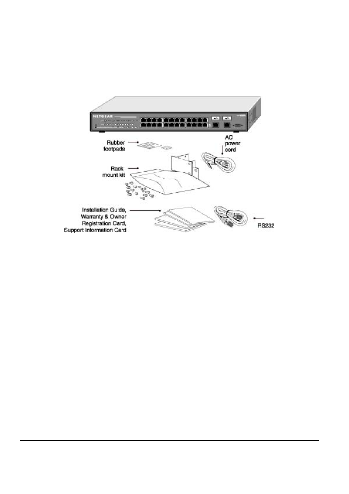
Figure 1-1 shows the package contents for the Managed Stackable Switch (FSM726S shown).
Figure 1-1: Package Contents
Verify that your package contains the following:
One FSM726S or FSM750S Managed Stackable Switch
Rubber footpads for tabletop installation
Power cord
One null-modem cable
One stacking cable
Rack-mount kit for installing the switch in a 19-inch rack
This user’s guide
Support Information Card
Warranty & Owner Registration Card
If you ordered additional GBIC modules with your switch, they are provided in a separate package.
If any item is missing or damaged, contact your place of purchase immediately.
Page 11 of 121
Page 13

Page 12 of 121
Page 14
CHAPTER 2: PHYSICAL DESCRIPTION
This chapter describes the hardware features of the NETGEAR Model FSM726S and FSM750S Managed Stackable Switch. Topics include:
Front and back panels
10/100 Mbps auto-sensing RJ-45 ports
Gigabit Ethernet Ports (RJ-45 and GBIC module bay)
LED descriptions
Console port
Stacking ports
Front Panels
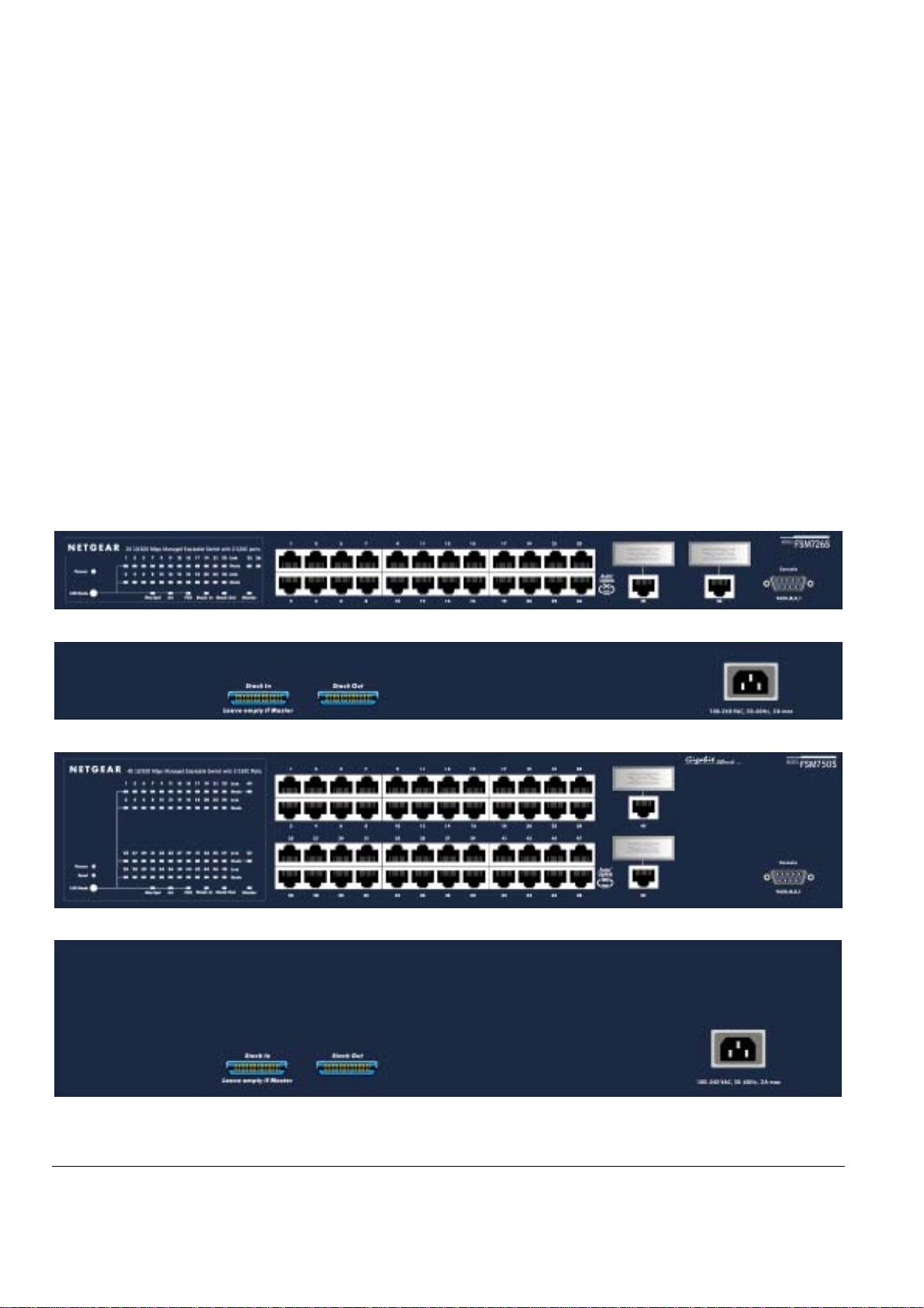
Figures 2-1 and 2-2 show the key components on the front and back panels of the NETGEAR Model FSM726S and FSM750S Managed Stackable
Switch
The front panel contains LEDs, RJ-45 jacks, GBIC module bays, and a console port. The back panel has two stacking ports and a standard AC
power receptacle for accommodating the supplied power cord.
Figure 2-1: Front Panel of the FSM726S Managed Stackable Switch
Figure 2-2: Back Panel of the FSM726S Managed Stackable Switch
Figure 2-3: Front Panel of the FSM750S Managed Stackable Switch
Figure 2-4: Back Panel of the FSM750S Managed Stackable Switch
Page 13 of 121
Page 15
10/100 Mbps RJ-45 Ports
As Figures 2-1 and 2-3 shows, the FSM726S and FSM750S Managed Stackable Switch have either 24 or 48 10/100 Mbps RJ-45 ports. These
ports are auto-sensing 10/100 Mbps ports: When you insert a cable into an RJ-45 port, the switch automatically ascertains the maximum speed (10
or 100 Mbps) and duplex mode (half- or full-duplex) of the attached device. The 10/100 Mbps ports support only unshielded twisted-pair (UTP)
cable terminated with an 8-pin RJ-45 plug.
To simplify the procedure for attaching devices, all RJ-45 ports support Auto Uplink. This technology lets you attach devices to the RJ-45 ports
using either straight-through or crossover cables. When you insert a cable into the switch’s RJ-45 port, the switch automatically:
Senses whether the cable is a straight-through or crossover cable, and
•
• Determines whether the link to the attached device requires a “normal” connection (such as when connecting the port to a PC) or an
“uplink” connection (such as when connecting the port to a router, switch, or hub).
After ascertaining this information, the switch automatically configures the RJ-45 port to enable communications with the attached
•
device, without requiring user intervention. In this way, the Auto Uplink technology compensates for setting uplink connections, while
eliminating concern about whether to use crossover or straight-through cables when attaching devices.
Warning! You must use Link Aggregation (a.k.a. Port Trunking) to create multiple links between switches. Using Auto Uplink to create multiple
active paths between any two network devices can cause undesirable loops in the network, resulting in an endless broadcast traffic that disables
your network. Loops occur when there are alternate routes between two network devices. In Figure 2-3, for example, a loop is created by
connecting two RJ-45 ports on a NETGEAR Model FSM726S Managed Stackable Switch to a router containing a 4-port switch. The Spanning Tree
protocol will prevent loops, if that advanced feature is enabled.
Figure 2-5: Warning! Creating Redundant Paths between Network Devices
Gigabit Ethernet Ports (RJ-45 and GBIC module bay)
Your NETGEAR Model FSM726S and FSM750S Managed Stackable Switch have two Gigabit Ethernet ports that can be used as either a
1000BASE-T port or as a GBIC module bay. The default setting for those ports are for the built-in RJ-45 connector to be active, but they can be
independently configured to activate either the RJ-45 or the GBIC module, enabling multiple combinations of fiber and copper connections. The
Gigabit Ethernet ports provide a full-duplex 1000 Mbps (1 Gbps) connection that effectively doubles throughput to 2 Gbps.
The GBIC bay accommodates a standard GBIC module, such as the NETGEAR AGM721F 1000BASE-SX GBIC module. This module has an SC
connector that is compatible with the IEEE 802.3z 1000BASE-SX standard.
Page 14 of 121
Page 16

LED Descriptions
The front panels of the NETGEAR Model FSM726S and FSM750S Managed Stackable Switch have LEDs that provide a quick and accurate
display of port speed, activity, collisions, and duplex mode. For stacked use, there are additional LEDs for link status and master unit status (to
indicate master/slave status in a stack). The Gigabit Ethernet ports also have LEDs that show link and mode status. Table 2-1 summarizes the
LEDs on the switch and Gigabit Ethernet module.
Table 2-1. Front Panel LEDs:
Label Color Activity Description
Power Green
Link
(the port number)
LED Mode in (Three LEDs)
Max Spd
ACT
FDX
Stack In Green On
Stack Out Green On
Master Green On
Yellow
Green On
Green
Green
Green
Yellow
Blinking
Blinking
Blinking
On
On
Off
Off
On
Off
Off
On
On
Off
Off
Off
Power is supplied to the switch.
Power On Self Test (POST) in progress
Hardware failure during POST
Power is disconnected
Port has a valid link connection.
A valid link has not been established on the port.
Port has made a connection at the fastest speed possible for that port. For
10/100 Mbps ports, it indicates a 100 Mbps connection. For a 10/100/1000
Mbps port, it indicates a 1 Gbps connection.
Port is not operating at the fastest speed possible.
Data transmission is occurring on the port.
No data transmission is occurring on the port.
Port is operating in full-duplex mode.
Port is operating in half-duplex mode.
Collision is occurring.
Stack In port has a valid link connection.
Stack In port does not have a valid link connection
Stack Out port has a valid link connection.
Stack Out port does not have a valid link connection
Switch acts as a master unit in a stack of FSM700S switches.
Switch acts as a slave unit in a stack of FSM700S switches.
Console Port
Your NETGEAR Model FSM726S or FSM750S Managed Stackable Switch has a console port on the front panel. This port is labeled Console and
is required for initial management configuration of the switch. It also lets you manage the switch using a directly connected VT-100 terminal,
personal computer (PC), Apple Macintosh, or UNIX workstation. The terminal, computer, or workstation connects to the console port using
the null-
modem cable supplied with your switch.
The console port is configured to use the following settings:
• Baud rate: 9,600 bps
• Data bits: 8
• Parity: none
• Stop bit: 1
• Flow control: none
These settings appear below the connector on the switch front panel.
In addition to using the console port, you can manage the switch using a Web browser and/or a Simple Network Management Protocol ( SNMP)
management program.
Note: You must use the console port for the initial management configuration.
For more information about console-port connections, see “Connecting to the Console Port” on page 20. For more information about managing the
switch, see Chapter 5.
Stacking Ports
Your NETGEAR Model FSM726S or FSM750S Managed Stackable Switch has two stacking ports on the back panel, each with a full-duplex
throughput of 2.6 gigabit per second (Gbps). These ports are labeled Stack In and Stack Out. You can use the stacking ports to cascade
NETGEAR Model FSM726S and FSM750S Managed Stackable Switches as your network grows to a maximum of 144 10/100 Mbps ports. The
front panel of the switch contains Stack In and Stack Out LEDs that show link on these stacking ports. For more information about stacking
switches, see “Connecting Switches to the Stack’s Backplane” on page 20.
Page 15 of 121
Page 17

Page 16 of 121
Page 18
CHAPTER 3: APPLICATIONS
Your NETGEAR Model FSM726S or FSM750S Managed Stackable Switch is designed to provide flexibility in configuring your network connections.
It can be used as stand-alone devices or used with 10 Mbps, 100 Mbps, 10/100 Mbps, and 1000 Mbps hubs and switches. It can also be stacked
with other FSM700S Switches to create one large virtual switch. This chapter shows how the switch can be used in various network environments.
Topics include:
Desktop switching
Stacked Switching
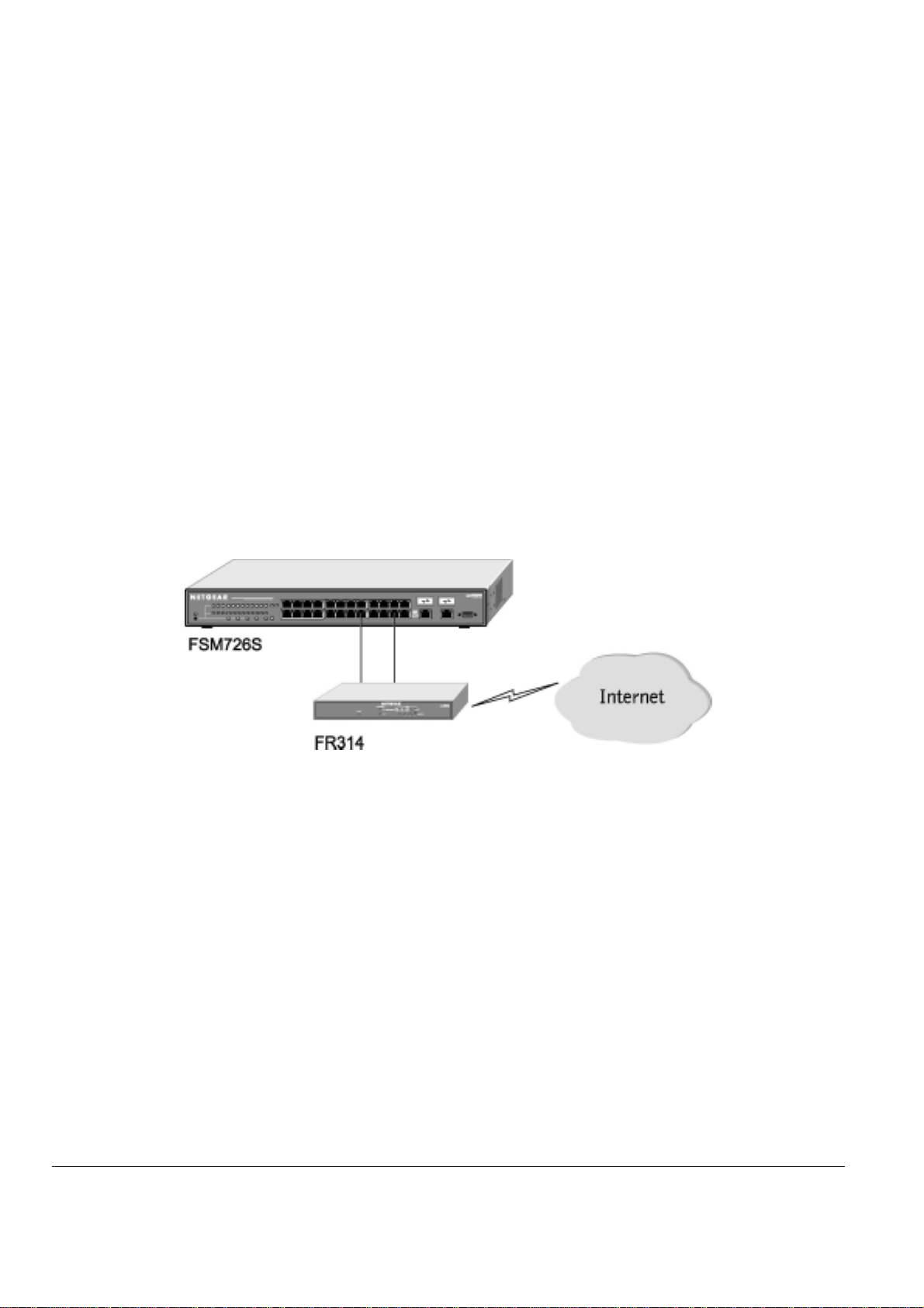
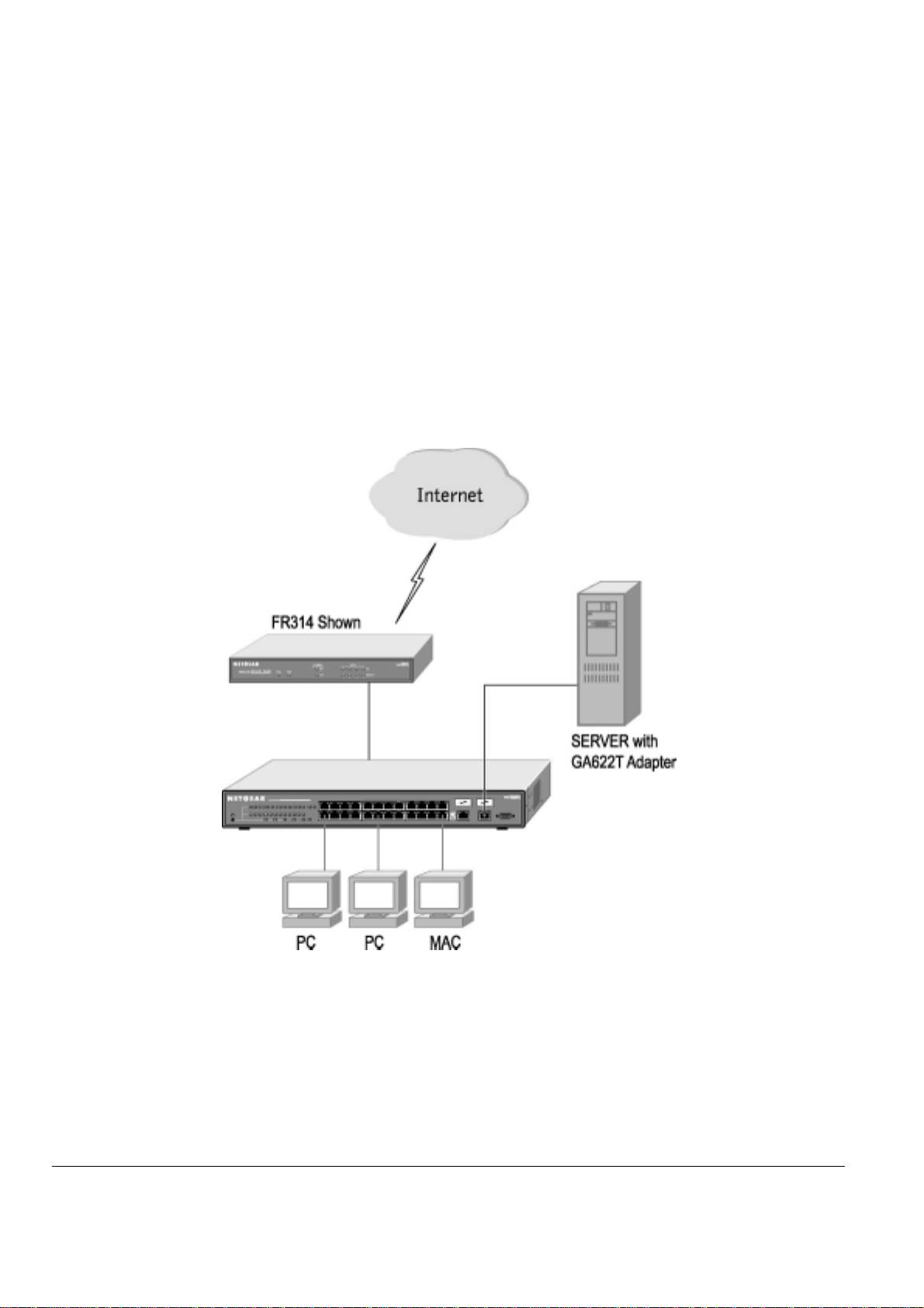
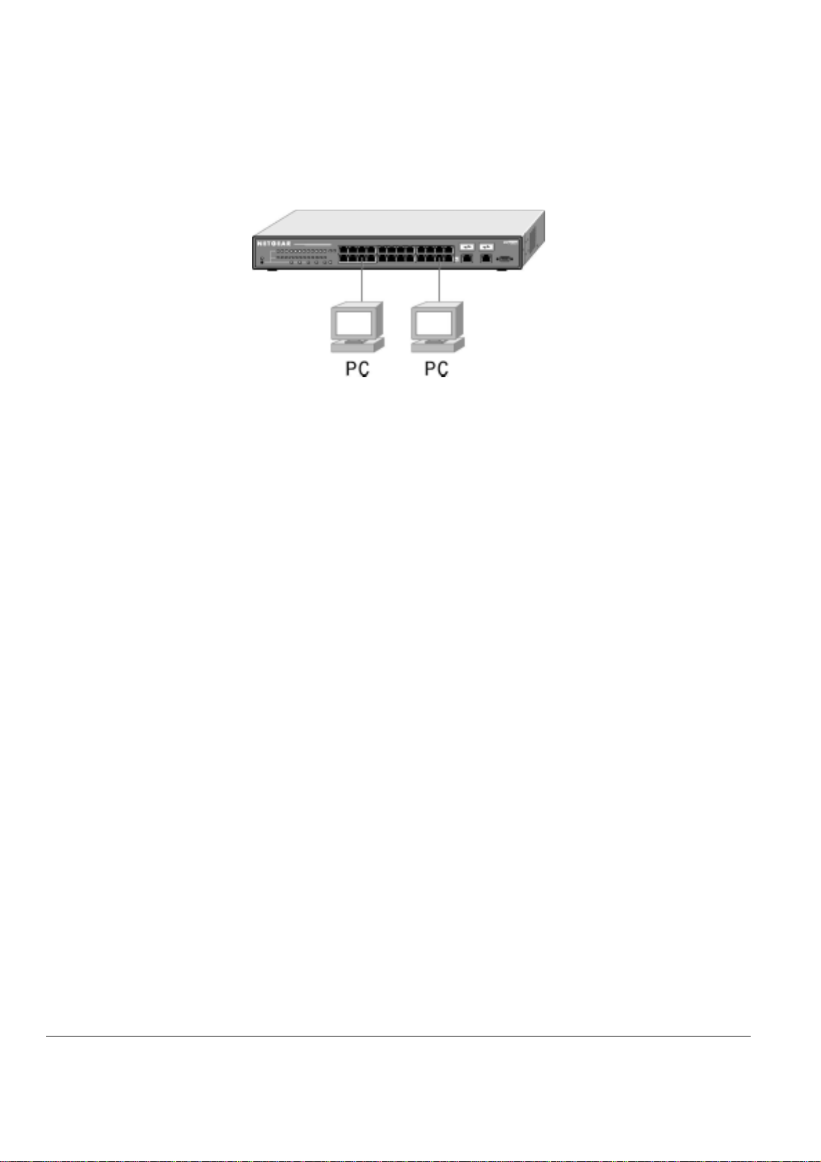
Desktop Switching
Your NETGEAR Model FSM726S or FSM750S Managed Stackable Switch can be used as desktop switch to build a small network that enables
users to have 1000 Mbps access to a file server. With full-duplex enabled, the switch port connected to the server or PC can provide 2000 Mbps
throughput.
Figure 3-1: Example of Desktop Switching
Page 17 of 121
Page 19
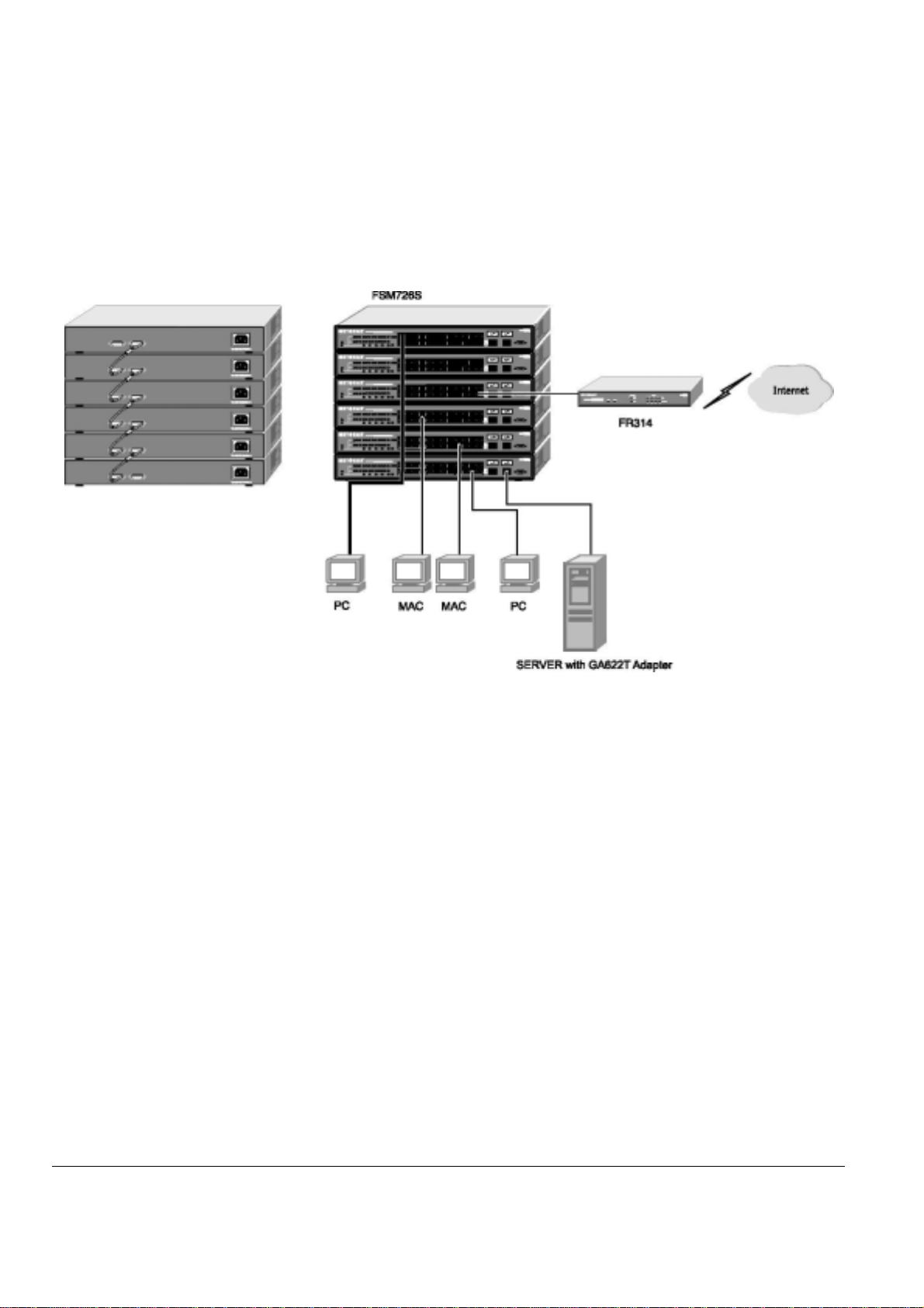
Stacked Switching
Your NETGEAR Model FSM726S Managed Stackable Switch has two bi-directional stacking ports on the back panel. Using these ports, you can
build a full-duplex, switched network for large numbers of users simply by stacking units together. The high-speed stacking ports deliver more than
2 Gbps of throughput across the stacking backplane.
A total of 144 10/100 ports can be put into a single stack. Stacked FSM726S Managed Stackable Switches can be assigned a single IP address
using the switch’s management software. The stack can then be treated as a single manageable unit with one IP address.
Figure 3-2: Example of Switched Stacking
Page 18 of 121
Page 20

CHAPTER 4: INSTALLATION
This chapter describes the installation procedures for your NETGEAR Model FSM726S or FSM750S Managed Stackable Switch. Switch
installation involves the following steps:
Step 1: Preparing the site
Step 2: Installing the switch
Step 3: Installing a GBIC module
Step 4: Connecting Switches to the Stack’s Backplane
Step 5: Checking the installation
Step 6: Applying AC power
Step 7: Connecting to the console port to manage the switch (initial configuration)
Step 8: Connecting devices to the switch
This chapter also discusses how to add or remove switches to your stack
Step 1: Preparing the Site
Before you install your switch, be sure your operating environment meets the operating environment requirements in Table 4-1.
Table 4-1. Site Requirements
Characteristics Requirements
Mounting
Desktop installations:
Rack-mount installations:
Provide a flat table or shelf surface.
Use a 19-inch (48.3-centimeter) EIA standard equipment rack that is grounded and physically
secure. You also need the rack-mount kit supplied with your switch.
Access
Power source
Environmental
Temperature: Install the switch in a dry area, with ambient temperature between 0 and 40ºC (32 and 104ºF).
Operating humidity: The installation location should have a maximum relative humidity of 90%, non-condensing.
Ventilation: Do not restrict airflow by covering or obstructing air inlets on the sides of the switch. Keep at least
Operating conditions: Keep the switch at least 6 ft (1.83 m) away from nearest source of electromagnetic noise, such as
Stacking If you intend to stack two or more switches, be sure the mounting surface can safely support the
Locate the switch in a position that lets you access the front panel RJ-45 ports, view the front
panel LEDs, and access the rear-panel stacking port(s) and power connector.
Provide a power source within 6 feet (1.8 meters) of the installation location. Power specifications
for the switch is shown in Appendix C. Be sure the AC outlet is not controlled by a wall switch,
which can accidentally turn off power to the outlet and the switch.
Keep the switch away from heat sources such as direct sunlight, warm air exhausts, hot-air vents,
and heaters.
2 inches (5.08 centimeters) free on all sides for cooling.
Be sure there is adequate airflow in the room or wiring closet where you intend to install the
switch.
a photocopy machine.
switch stack. Also, be sure there is adequate space around the stack for ventilation and cooling.
Step 2: Installing the Switch
You can install your NETGEAR Model FSM726S or FSM750S Managed Stackable Switch on a flat surface or in a standard 19-inch rack.
Installing the Switch on a Flat Surface
The switch ships with four self-adhesive rubber footpads. Stick one rubber footpad on each of the four concave spaces on the bottom of the switch.
The rubber footpads cushion the switch against shock/vibrations. They also provide space between each stacked switch for ventilation.
Page 19 of 121
Page 21
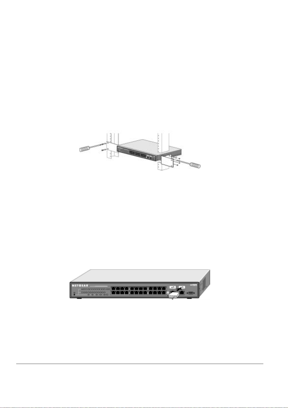
Installing the Switch in a Rack
To install the switch in a rack, use the following procedure (and refer to Figure 4-1). To perform this procedure, you need the 19-inch rack-mount kit
supplied with your switch.
1. Attach the supplied mounting brackets to the side of the switch.
2. Insert the screws provided in the rack-mount kit through each bracket and into the bracket mounting holes in the switch.
3. Tighten the screws with a #1 Phillips screwdriver to secure each bracket.
4. Align the mounting holes in the brackets with the holes in the rack, and insert two pan-head screws with nylon washers through each bracket
and into the rack.
5. Tighten the screws with a #2 Phillips screwdriver to secure the switch in the rack.
6. If you want to install a GBIC module, proceed to “Step 3: Installing a GBIC Module,” next. If you want to stack switches, proceed to “Step 4:
Connecting Switches to the Stack’s Backplane,” Otherwise, skip to “Step 5: Checking the Installation.”
Figure 4-1: Attaching Mounting Brackets
Step 3: Installing a GBIC Module
The following procedure describes how to install a GBIC Gigabit Ethernet module, such as the NETGEAR AGM721F, in the switch’s Gigabit
module bays. The AGM721F is sold separately from the FSM726S or FSM750S. If you do not want to install a GBIC module at this time, skip this
procedure.
To install a GBIC module:
1. Insert the GBIC module into the GBIC module bay. Press firmly to ensure the module seats into the connector.
2. After the switch has been configured for management (Step 7), use one of the management interfaces (web browser or console interface) to
configure the Gigabit Ethernet port with the GBIC module installed to the GBIC option.
3.To install a second Gigabit Ethernet module, repeat this procedure using the second module and the unoccupied module bay.
4.If you want to stack switches, proceed to “Step 4: Connecting Switches to the Stack’s Backplane,” next. Otherwise, skip to “Step 5: Checking the
Installation.”
Figure 4-2: Installing a Gigabit Ethernet Module into an FSM726S
Step 4: Connecting Switches to the Stack’s Backplane
Your NETGEAR Model FSM726S or FSM750S Managed Stackable Switch provides two stacking connectors. You can use these connectors to
cascade up to 144 10/100 Mbps ports to create one large virtual switch (for more information, see “Stacked Switching” on page 18).
Observe the following guidelines when installing the switches in a stacked configuration.
Connecting Stacking Ports
When connecting two Managed Stackable Switches, one stacking cable connects the stacking port on one switch to the stacking port on the other
switch.
Page 20 of 121
Page 22
Connect Straight-in
To prevent bent pins, do not install the stack port cable connector at an angle. Use extra care to insert the cable connector straight into the switch’s
stacking connector.
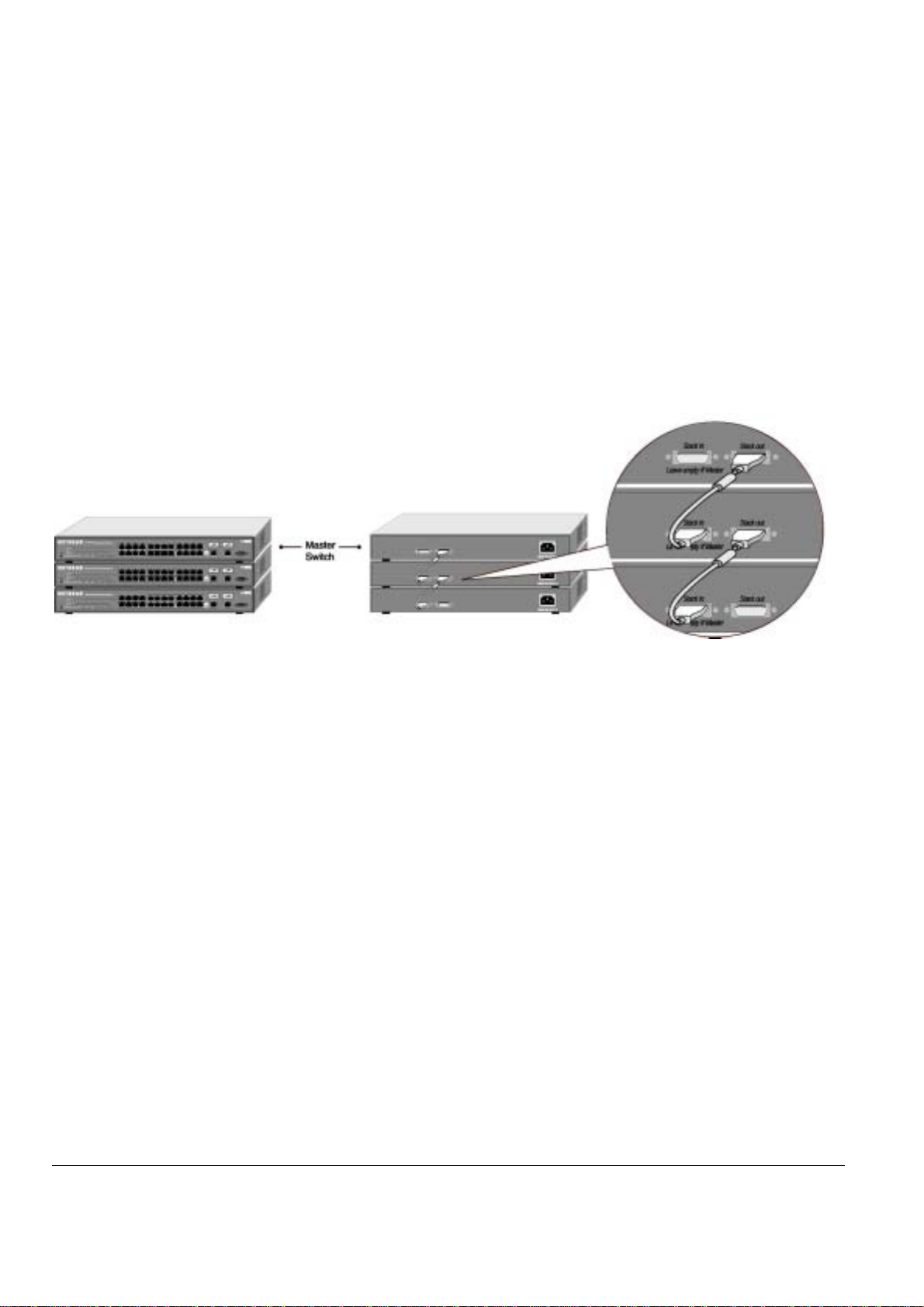
The following procedure describes how to stack three FSM726S Managed Stackable Switches This procedure is the same if you are stacking
FSM750S Managed Stackable Switches or a combination of the two. Figure 4-3 shows these connections:
1.Connect either end of the supplied stacking cable to the Stack In connector on the first switch. Connect the other end of the cable to the Stack
Out connector on the second switch.
2.Connect either end of another stacking cable to the Stack In connector on the second switch. Connect the other end of the cable to the Stack Out
connector on the third switch. The third switch will be the master switch.
Note: Stacked Switches can be assigned a single IP address using the switches’ management software. The stack can then be treated as a single
manageable unit with one IP address. The switch with that IP address is considered the master unit, while the other switches in the stack are
called slave units.
Note: The switch that is acting, as the master unit should have the Stack In port empty.
Figure 4-3: Cabling Three FSM726S Stacked Switches
Step 5: Checki n g the Install ation
Before you apply power:
Inspect the equipment thoroughly.
o
Verify that all cables are installed correctly.
o
Check cable routing to make sure cables are not damaged or create a safety hazard.
o
Be sure all equipment is mounted properly and securely.
o
Step 6: Applying AC Power
NETGEAR Model FSM726S and FSM750S Managed Stackable Switches do not have an ON/OFF switch; the only method of applying or removing
AC power is by connecting or disconnecting the power cord. Before you connect the power cord, select an AC outlet that is not controlled by a wall
switch, which can turn off power to the switch. After you select an appropriate outlet, use the following procedure to apply AC power.
1.Connect the female end of the supplied AC power adapter cable to the power receptacle on the back of the switch.
2.Connect the 3-pronged end of the AC power adapter cable to a grounded 3-pronged AC outlet.
When you apply power, the Power LED on the switch’s front panel will be Yellow, as it conducts a Power On Self Test (POST). After the switch
passes the POST, the Power LED will change to Green and the switch is functional and ready to pass data.
If the Power LED does not go on, check that the power cable is plugged in correctly and that the power source is good. If this does not resolve the
problem, refer to Appendix B, Troubleshooting.
Note: If you are powering up stacked switches, power up the master unit last.
Step 7: Connecting to the Console Port to Manage the Sw itch (initial conf i guration)
Your NETGEAR Model FSM726S or FSM750S Managed Stackable Switch contains software for viewing, changing, and monitoring the way it
works. This management software is not required for the switch to work. You can use the 10/100 Mbps ports, the built-in RJ-45 Gigabit ports, and
the stacking ports without using the management software. However, the management software can let you improve the efficiency of the switch
Page 21 of 121
Page 23

and, as a result, improve its overall performance as well as the performance of your network. The remainder of this section describes how to
initialize the management software to the first time you use the management features.
After you power-up the switch for the first time, you can configure it using a VT100/ANSI terminal or a PC, Apple Macintosh, or UNIX workstation
that is directly connected to the switch’s console port. Thereafter, you can assign an IP address, subnet mask, and gateway address to the switch
and manage it through a Web browser, Telnet session, or SNMP management application. For more information about using the console, see
Chapter 6, Administration Console Access.
This example shows screenshots of the FSM726S, but the procedure is the same for the FSM750S.
To connect a console to the switch:
1. Connect a VT100/ANSI terminal or a PC, Apple Macintosh, or UNIX workstation to the switch’s console port, labeled Console, using the null-
modem cable supplied with the switch. The supplied null-modem cable has 9-pin connectors on each end.
Note: you must connect the console cable to the master switch. Connecting the console cable a slave switch will not allow configuration.
Note: If you are stacking your switches, you only have to configure the Master unit via the Console port. Once you have assigned an IP address to
the master unit, you can use the browser interface to configure the other units.
2. If you attached a PC, Apple Macintosh, or UNIX workstation, start a terminal-emulation program.
Microsoft Windows users can use HyperTerminal, which comes with the Windows operating systems.
Macintosh users can use ZTerm.
UNIX users can use a terminal emulator such as TIP.
3. Configure the terminal-emulation program to use the following settings:
Baud rate: 9,600 bps
Data bits: 8
Parity: none
Stop bit: 1
Flow control: none
Page 22 of 121
Page 24
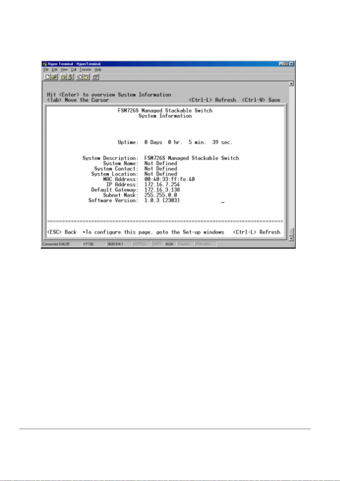
Figure 4-4: System Description
4. The terminal-emulation program should display the System Description page. Hit the ‘ESC’ key to get to the Main Menu page
.
Page 23 of 121
Page 25
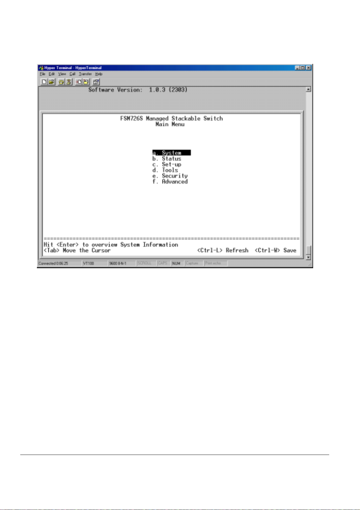
Figure 4-5: Main Menu
5. On the Main Menu page, hit the ‘C’ key to select the Set Up page
Page 24 of 121
Page 26
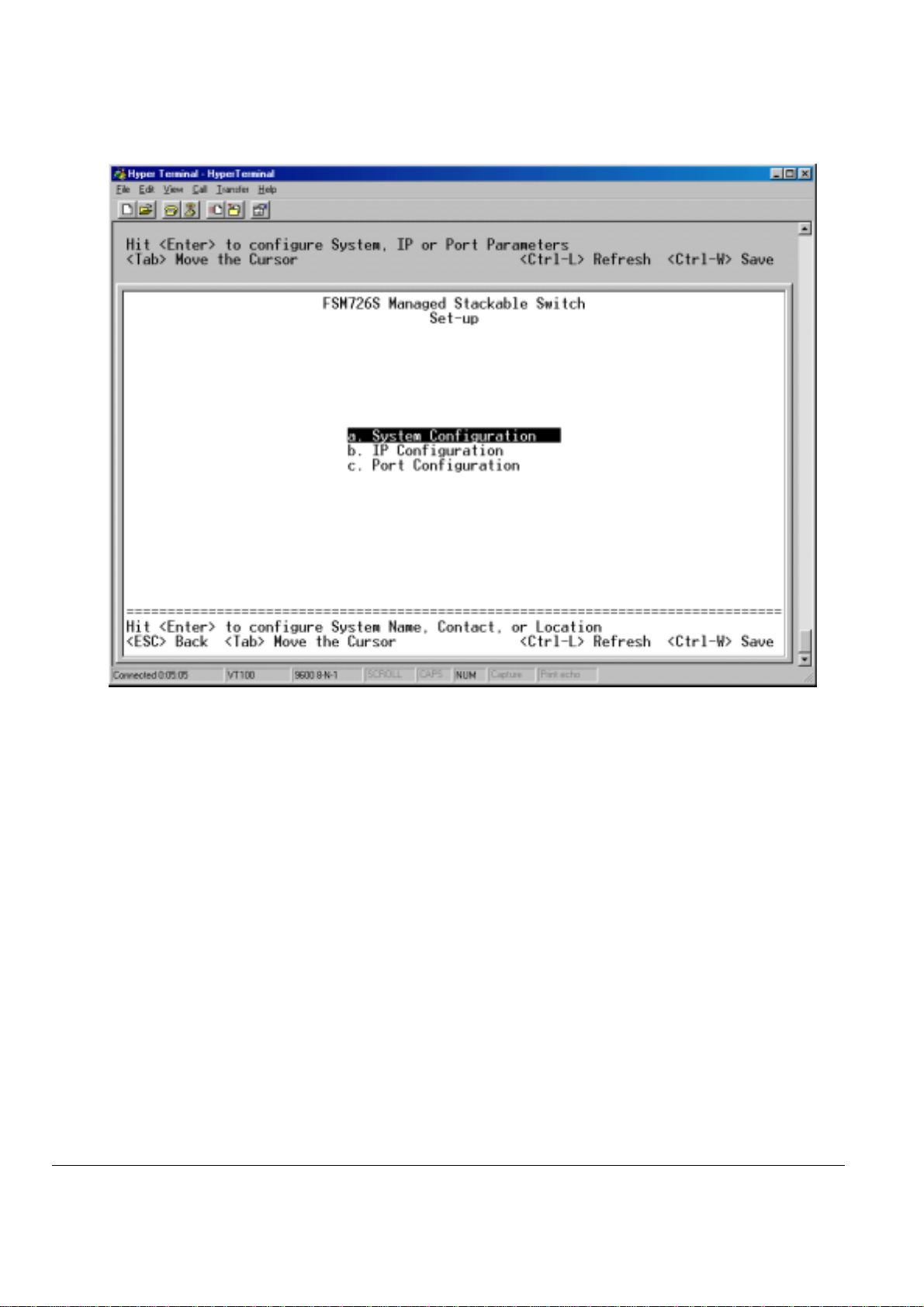
Figure 4-6: Set-Up
6. On the Set Up page, hit the ‘B’ key to select the IP Configuration page.
Page 25 of 121
Page 27
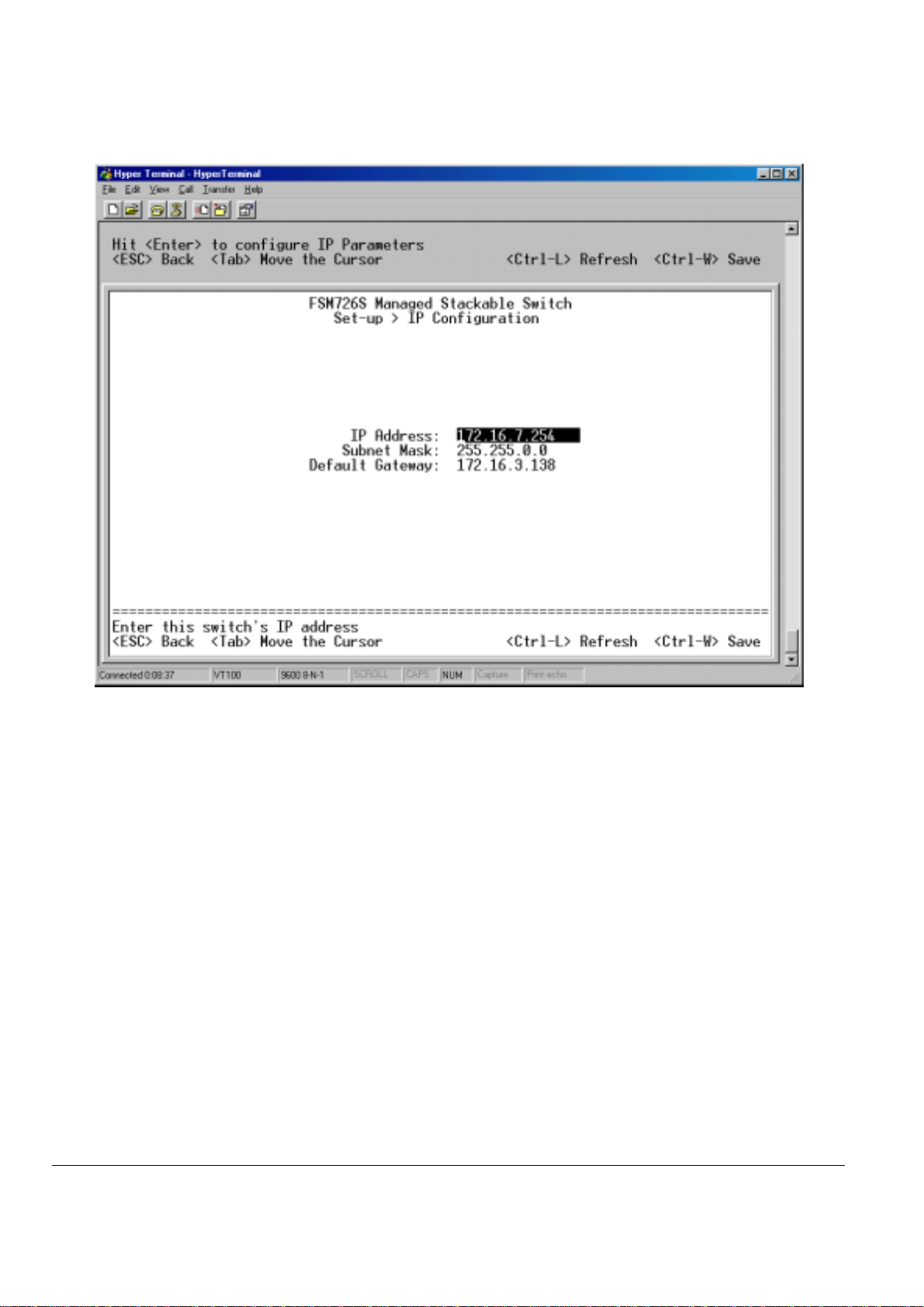
Figure 4-7: IP Configuration
7. On the IP Configuration page, type in the desired IP Address for this switch, followed by the ‘Enter’ key.
Note: this switch is not DHCP client capable. You must assign a static IP address to the master switch.
8. Now type in the desired Network Mask, followed by the ‘Enter’ key.
9. Now type in the desired Default Gateway, followed by the ‘Enter’ key.
10. Use Ctrl-W to save these new settings. Hit the ‘Y’ key or ‘Enter’ to confirm saving the new settings to NVRAM.
11. Now hit the ‘ESC’ key twice to return to the Main Menu.
12. On the Main Menu page, hit the ‘D’ key to select the Tools page.
Page 26 of 121
Page 28
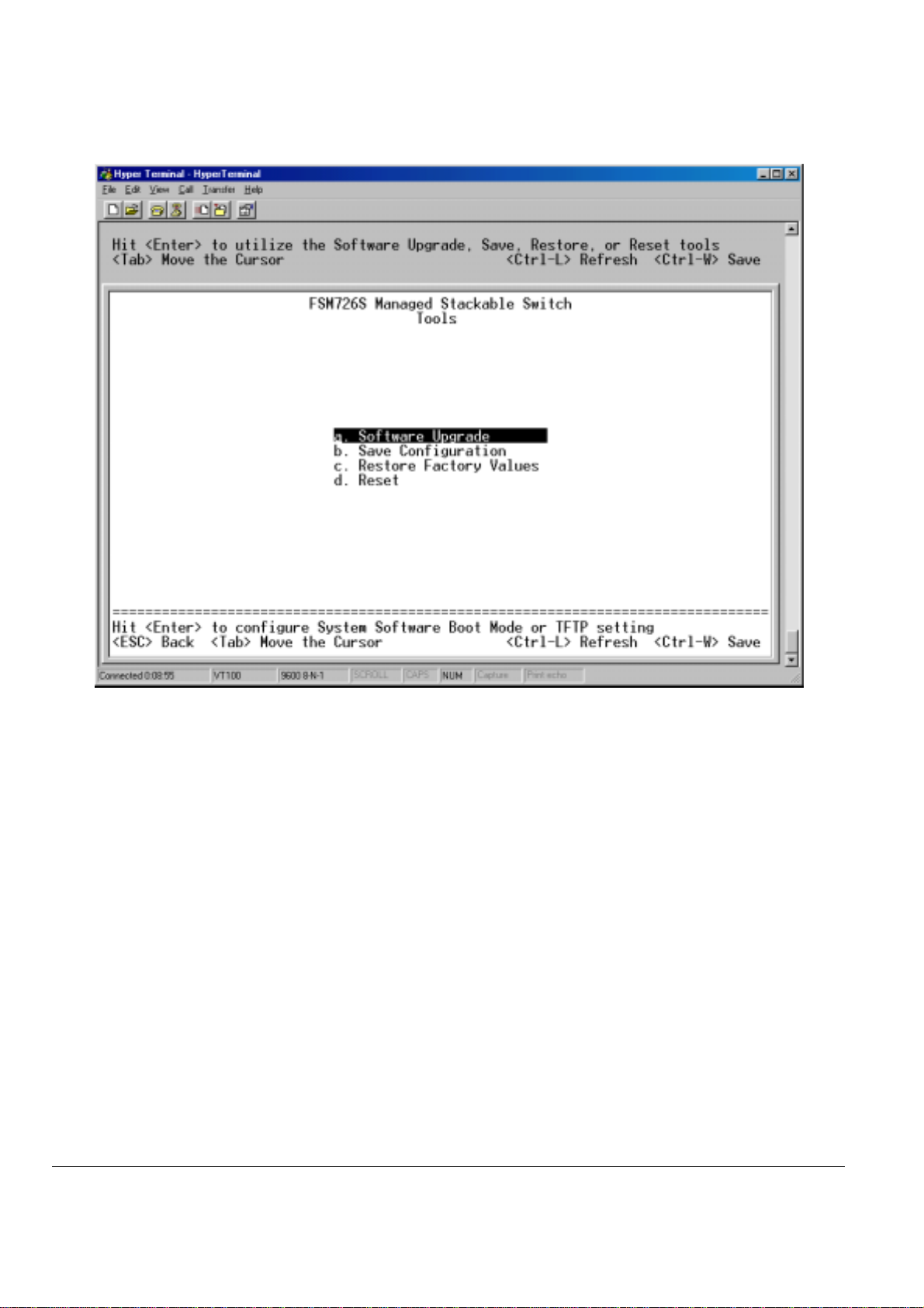
Figure 4-8: Tools page
13. On the Tools page, hit the ‘D’ key to Reset the switch. Hit the ‘Y’ key or ‘Enter’ to confirm resetting the switch.
The switch will now reset, loading the new IP address. At this point you can use your web browser to manage your switch through the network.
After you have connected your computer to the switch via one of the network ports, simply launch your web browser and type the IP address in the
Address Bar to use the Graphical User Interface (GUI) for configuration, observation, and management of your switch.
Page 27 of 121
Page 29
Step 8: Connecting Devices to the Switch
The following procedure describes how to connect devices to the switch’s RJ-45 ports. Your NETGEAR Model FSM726S or FSM750S Managed
Stackable Switch contains Auto Uplink™ technology, which allows you to attach devices using either straight-through or crossover cables.
Figure 4-9: Connecting Devices to the Switch
Connect each device to an RJ-45 network port on the switch’s front panel (see Figure 4-9). Use Category 5 (Cat5) unshielded twisted-pair (UTP)
cable terminated with an RJ-45 connector to make these connections.
Note: Ethernet specifications limit the cable length between the switch and the attached device to 100 m (328 ft).
Addin g or Rem o vi n g Sw i tc he s to t he st ac k
For the master unit to properly manage the stack, we recommend the following steps when adding or removing a switch from the stack
1. Power down all switches in
Note: Do not add or remove stacking cables while the switch is powered up.
2. Remove/Add the necessary switches
Note: the Stack In port on the master unit is always empty.
3. Power up the slave units in the stack.
4. Power up the master unit
the stack.
Page 28 of 121
Page 30

CHAPTER 5: SWITCH MANAGEMENT OVERVIEW
This chapter gives an overview of switch management, including the methods you can use to manage your NETGEAR Model FSM726S or
FSM750S Managed Stackable Switch. Topics include:
Management Access Overview
SNMP Access
Protocols
Software Upgrade Procedure
Management Access Over view
Your NETGEAR Model FSM726S or FSM750S Managed Stackable Switch gives you the flexibility to access and manage the switch using any or
all of the following methods:
An administration console
Web browser interface
External SNMP-based network-management application
The administration console and Web browser interface support are embedded in the switch’s firmware and available for immediate use. Each of
these management methods has advantages. Table 5-1 compares the three management methods.
Table 5-1. Comparing Switch Management Methods
Management Method Advantages Disadvantages
Administration console Out-of-band access via direct cable connection
Web browser Can be accessed from any location via the switch’s
SNMP Agent
means network bottlenecks, crashes, and downtime
do not slow or prevent access
No IP address or subnet needed
Menu-based
HyperTerminal access to full functionality
(HyperTerminal are built into Microsoft Windows
95/98/NT/2000 operating systems)
Secure – MAKE SURE THE AREA WHERE THE
SWITCH IS INSTALLED IS A SECURE AREA
IP address
Ideal for configuring the switch remotely
Compatible with Internet Explorer and Netscape
Navigator Web browsers
Familiar browser interface
Graphical data available
Most visually appealing
Communicates with switch functions at the
Management Information Base (MIB) level
Based on open standards
For a more detailed discussion of the Administration Console, see chapter 6. For a more detailed discussion of the Web Browser Interface, see
chapter 7.
Must be near switch or use dial-up connection
Not convenient for remote users
Not graphical
.
Security can be compromised (hackers need
only know IP address and subnet mask)
May encounter lag times on poor connections
Displaying graphical objects over a browser
interface may slow navigation
Requires SNMP manager software
Least visually appealing of all three methods
Limited amount of information available
Some settings require calculations
Security can be compromised (hackers need
only know the community name)
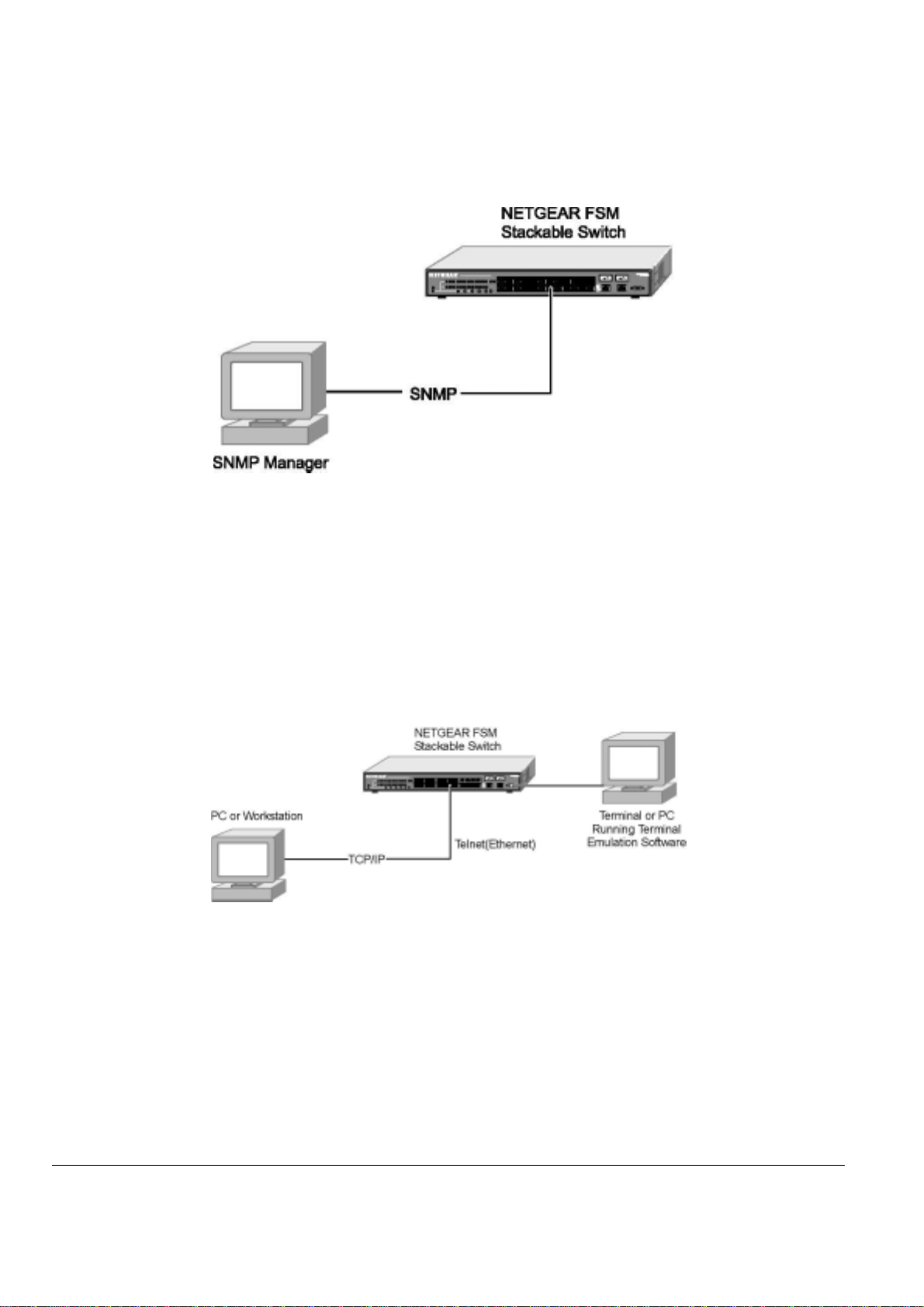
SNMP Access
With this access method, you can use an external Simple Network Management Protocol (SNMP) -based application to manage your NETGEAR
Model FSM726S or FSM750S Managed Stackable Switch. Figure 5-1 shows an example of this management method.
This management method requires the SNMP agent on the switch and the SNMP Network Management Station to use the same community string.
This management method, in fact, uses two community strings: the GET community string and the SET community string. If the SNMP Network
Page 29 of 121
Page 31
management Station only knows the SET community string, it can read from and write to the MIBs. However, if it only knows the GETcommunity
string, it can only read MIBs. The default GET community string for the switch is ‘public’.
Figure 5-1: SNMP-Based Management Method
Protocols
Your NETGEAR Model FSM726S or FSM750S Managed Stackable Switch supports the following protocols:
Virtual terminal protocols, such as Telnet
SNMP
Virtual Terminal Protocols
A virtual terminal protocol is a software program, such as Telnet, that allows you to establish a management session from a Macintosh, a PC, or a
UNIX workstation. Because Telnet runs over TCP/IP, you must have at least one IP address configured on the NETGEAR Model
FSM726S/FSM750S Managed Stackable Switch before you can establish access to it with a virtual terminal protocol.
Terminal emulation differs from a virtual terminal protocol in that you must connect a terminal or PC directly to the console port. Figure 5-2 shows a
UNIX workstation connected to the system through a virtual terminal protocol (Telnet), and a terminal connecting directly to the console port
through a null-modem cable.
Figure 5-2: Administration Console Access
SNMP Protocol
SNMP is the standard management protocol for multi-vendor IP networks. SNMP supports transaction-based queries that allow the protocol to
format messages and to transmit information between reporting devices and data-collection programs. SNMP runs on top of the User Datagram
Protocol (UDP), offering a connectionless-mode service.
Software Upgrade Procedure
The application software is field upgradeable. The upgrade procedure and the required equipment are described in the following section.
Note that once the system is up, it is controlled by an executing application image residing in non-volatile memory. No software upgrade is possible
during this mode. The upgrade can only be done when the system is resetting. To initiate this sequence, the user must set the ‘Next Boot From’
configuration parameter to ‘Boot from Net’ during normal operation, and then perform a ‘reset’. When the ‘Boot from Net’ option is set, the switch
will start using an image residing on a TFTP server on the network. Be sure that the TFTP server residing on the network is accessible by the
switch. Once completed, the software version should be verified in the System page.
Page 30 of 121
Page 32

Note: It is highly recommended, though not necessary, to use a RS-232 serial port connection to the switch during the software upgrading
procedure. When using a Telnet Session or web interface alone, your connection to the switch will not be available until the switch has entered
forwarding mode. This takes approximately three minutes.
The upgrade procedure is as follow:
Go to Main Menu>Tools>Software Upgrade (in the Web or Console Interface).
1.
2. Select ‘Boot from Net’ option.
3. Verify information such as the IP address for the TFTP Server, Gateway IP address, and the file name and its path of the new image.
4. Save the setting in non-volatile memory. In the Browser interface, use the ‘Apply’ button, and the Tools> Save Configuration screen. In the
console interface, use Ctrl-W and confirm the change to NVRAM.
5. Restart the system via the Tools>Reset command
6. Bootstrap will retrieve the new image then pass control to it.
7. The system executes the new software image.
Note: the previous image in non-volatile memory will not be replaced by the new image using this option. The image in non-volatile memory will
only be over-written if ‘Boot from Net and Save’ option is selected.
8. Test your switch to make sure the new image is working correctly. If you decide to keep the new image, go to Software Download again.
Select ‘Boot from Net & Save’ option.
9. Save the setting in non-volatile memory. In the Browser interface, use the ‘Apply’ button, and the Tools> Save Configuration screen. In the
console interface, use Ctrl-W and confirm the change to NVRAM.
10. Restart the system via the Tools>Reset command
11. The new image should over-write the old image in non-volatile memory. Verify it by going to the Software Download screen and checking the
Software Release information.
Note: IP address, Network Mask, and Default Gateway are not affected by upgrading the software. The settings will still be in non-volatile memory.
Page 31 of 121
Page 33

Page 32 of 121
Page 34

CHAPTER 6: ADMINISTRATION CONSOLE ACCESS
The administration console is an internal, character-oriented, VT-100/ANSI menu-driven user interface for performing management activities. Using
this method, you can view the administration console from a terminal, PC, Apple Macintosh, or UNIX workstation connected to the switch’s console
port. Figure 6-1 shows an example of this management method.
Note: All screen shots for this chapter u se an FSM726S. Screen shots for the FSM750S are very si milar.
Figure 6-1: Administration Console Management Method
Direct Access
Direct access to the switch console is achieved by connecting the switch’s console port to a VT-100 or compatible terminal or to a PC, Apple
Macintosh, or UNIX workstation equipped with a terminal-emulation program. This connection is made using the null-modem cable supplied with
the switch.
The following list provides examples of terminal-emulation programs:
The terminal-emulation program should use the following settings:
The direct access management method is required when you configure the switch for the first time. Thereafter, we recommend you use the Web
management access method (described in chapter 7) to manage the switch.
HyperTerminal (which is built into the Microsoft Windows operating systems)
ZTerm (Apple Macintosh)
TIP (UNIX workstation)
Baud rate: 9,600 bps
Data bits: 8
Parity: none
Stop bit: 1
Flow control: none
The console, using VT100 terminal emulation, can be accessed from the RS-232 serial port or a telnet connection. The switch offers password
protection for this interface. All of the following examples of the Console’s User Interface show a screen capture from a telnet session.
Page 33 of 121
Page 35

When attached to the User Interface via a Telnet Session, the following must be set in order to use the arrow keys: Under the terminal pull down
menu choose Properties and make sure the VT100 Arrows option is turned on.
User Interface
The switch offers a menu-driven interface.
Characteristics
There are several characteristics to the User Interface pages that are necessary to know before proceeding to use it. The TAB key or the arrow
keys may be used to move within menus and sub-screens. At the bottom of every screen are some key commands available to the user for that
particular screen, as well as some helpful information.
The common keystrokes and their definitions and intricacies are listed below:
ESC Return to the previous menu or screen, or abort editing
Tab Select field
Ctrl-L Refresh the screen
Ctrl-D Log off (password enabled)
Ctrl-M Move to field (Switch Statistics and Port Configuration menus only)
Ctrl-W Saves current configuration to Non-Volatile RAM (NVRAM)
Spacebar Toggles between possible settings for a field
Enter Select a menu item, edit a field, or accept a value after editing a field
Ctrl-X Delete a table entry
Page 34 of 121
Page 36

The initial screen depends on if password protection has been enabled. If it has, it is the welcome screen, seen below in Figure 6-2. If there is no
password set on the system, the Main Menu will be displayed and access is granted immediately. By default, password protection is disabled. If
enabled, the default password is ‘1234’.
To enable password protection:
o Choose Security from the Main Menu
Toggle Password Protection to Enabled
o
Enter and verify new password
o
Save with Ctrl-W
o
Figure 6-2 Initial Welcome screen of User Interface (Password enabled)
Page 35 of 121
Page 37

Main Menu
The main menu displays all the sub-menus that are available. Striking ‘Enter’ when an option is highlighted will confirm the choice of the specified
sub-menu. The ‘hotkey’ or letter in front of each menu option can also be typed to directly choose that option. As shown in Figure 6-3, there are six
menu items to choose from:
o System
o Status
o Set-Up
Tools
o
Security
o
Advanced
o
To logout of the user interface, hit Ctrl-D at anytime during your telnet session. You will be brought back to the login screen (password enabled) or
Main Menu (password disabled).
Figure 6-3: Main Menu
Page 36 of 121
Page 38

Main Menu> System
This screen displays the following:
System uptime
System Description
System Name- user definable
System Contact-user definable
System Location-user definable
MAC Address
Figure 6-4: System Information
Page 37 of 121
Page 39

Main Menu> Status
There are two sub-menus at Status menu, the Switch Statistics and MAC Address Table.
Main Me n u > Status >Statistics
There are two sections in this screen. The Unit number at the top indicates the switch in the stack, and left-side Port-ID field allows you to choose a
port to be observed. To get to the left side, use Ctrl-M to move to that field. The central portion of the screen displays the basic statistics
associated with the port, which is highlighted at the Port-ID field.
Figure 6-5: Switch Statistics
Page 38 of 121
Page 40

Main Menu> Status > MAC Address Table (Dynamic Addresses)
The MAC Address lookup table allows you to view the dynamic MAC addresses that are currently in the address database. When addresses are in
the database, the packets intended for those addresses are forwarded directly to those ports. You can filter out addresses in the table by port,
VLAN, and/or MAC address by entering a value in those fields, and selecting ‘Query’.
Figure 6-6: Address Manager: MAC Address Table
Page 39 of 121
Page 41

Main Menu> Set-Up
There are two sub-menus at Set-Up menu, Port Configuration and IP Configuration.
Main Menu> Set-Up> Port Configuration
On this page, you can set up the port characteristics related to link operations (see Figure 6-7). All of the parameters on this page are toggle
settings. To change, or toggle, between options, hit Ctrl-M to move the curser to the ports field and simply strike the space bar when the
appropriate option is highlighted. To modify ports 17 to 26, you must tab through ports 1 to 16. The comments field is available for you to enter a
description of the port.
Admin field
Allow you to Enable or Disable the port.
State
The State field displays the Spanning Tree State of the port (Blocking, Listening, Learning, Forwarding, or Disabled). You can only observe the
status of the ports; you cannot modify this field. The Spanning Tree Protocol controls this field.
Rate/Duplex field
Offers the choice of Full-duplex, Half-duplex, or Auto negotiation.
Enabling auto-negotiation on a port allows a port to sense the communication speed and negotiate the duplex mode (full duplex or half duplex)
automatically. The ports will select the highest possible throughput. The port can auto-negotiate with any port that is compliant with IEEE 802.3u. If
the other port is not IEEE802.3u compliant, the port will default to half-duplex, 10 Mbps mode. Users can operate the communication speed and
duplex mode manually.
Flow Control
Allow you to enable or disable Flow Control.
Flow control is a protocol that prevents packets from being dropped by reducing the amount of traffic to a level that can be accommodated. If
enabled on both ends of a connection, it will prevent the sender from sending data until the receiver can accept it. This switch complies with the
IEEE802.3x flow control standard.
Comments
Allow you to name the port or make notes.
Gigabit Ports
For the two-gigabit ports on each switch in the stack, the port type may be chosen. The default is that the port uses the RJ-45 interface. If so
chosen, the user may use a GBIC interface. If so, the user must switch the port type from ‘GT’ to ‘GB’. This can be done by hitting the space bar on
the two letters next to the port number.
: enabling the GBIC connector for a Gigabit Ethernet port disables the built-in 1000BASE-T port.
Note
Note: GBIC ports do not support Auto Negotiation. You must manually configure the GBIC port. The default values are 1000 Mbps, full duplex
.
Page 40 of 121
Page 42

Figure 6-7: Port Configuration
Page 41 of 121
Page 43
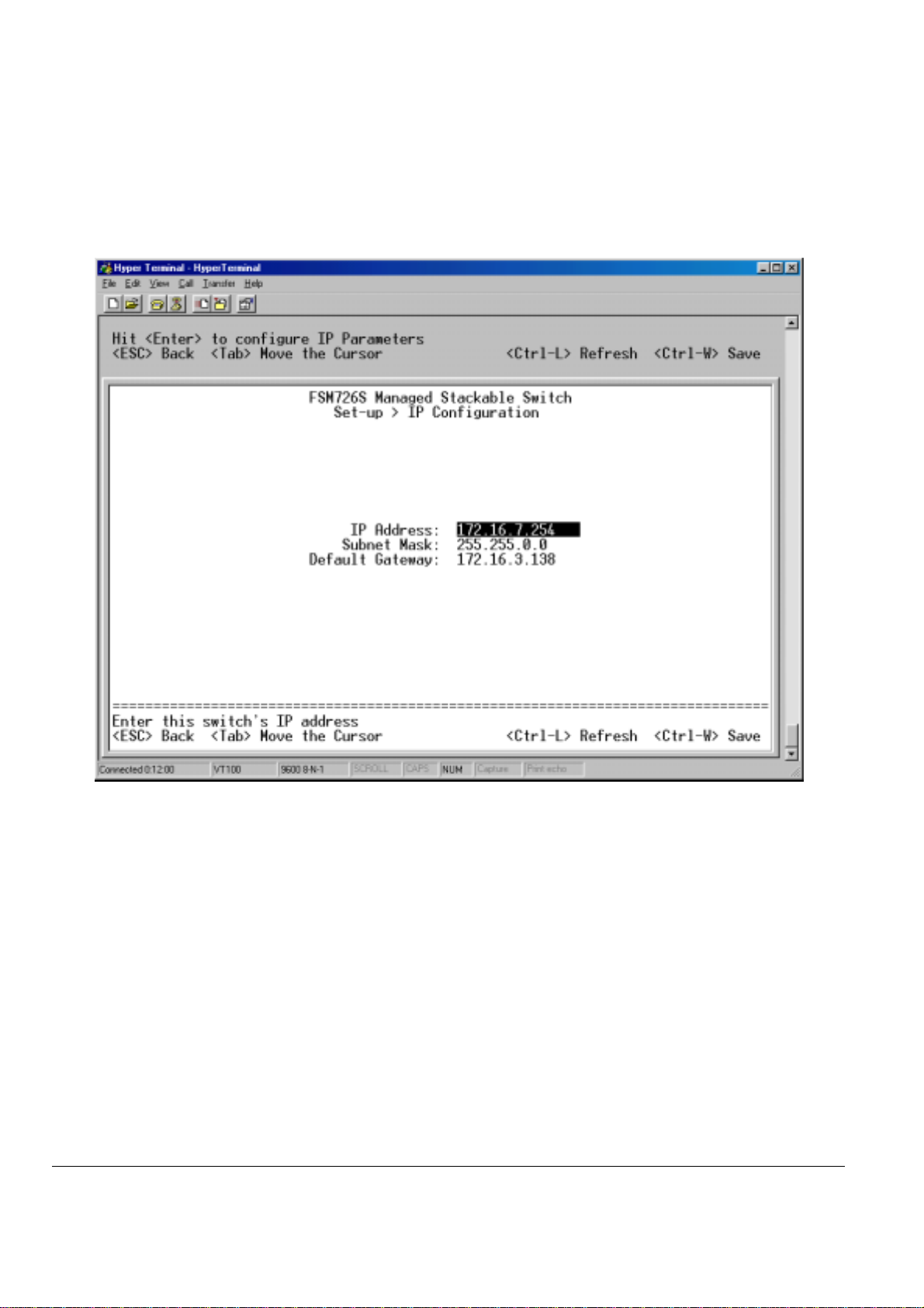
Main Menu> Set-Up> IP Configuration
This menu manages the IP related information of the system.
o Enter a site-specific IP address, Gateway Address, and Network Mask (or subnet mask). Consult your network administrator for the
information.
Press Ctrl-W to save any changes to NVRAM.
o
Figure 6-8: Set-up Manager: IP Configuration
Page 42 of 121
Page 44
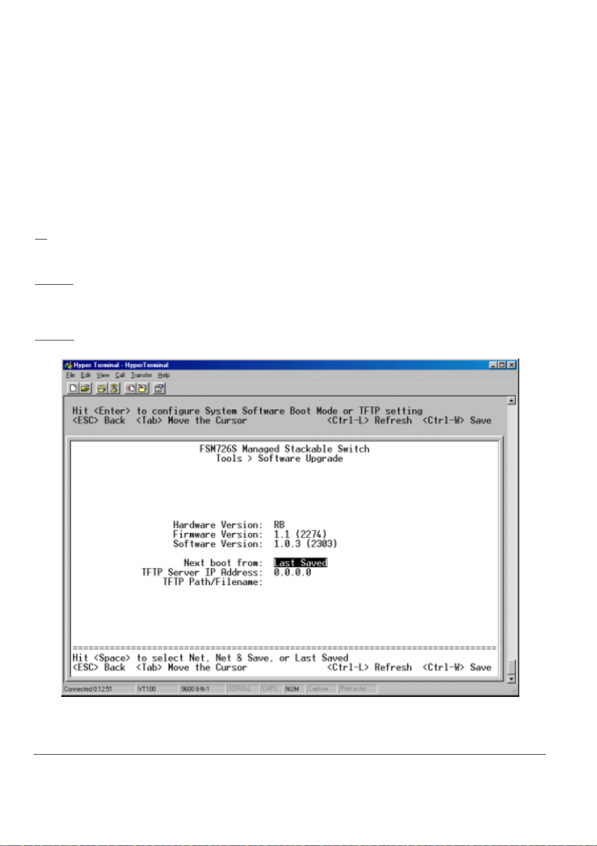
Main Menu> Tool s
There are some system setup tools provided:
Main Menu> Tools> Software Upgrade
This screen allows you to select an image file and the location from where it can be downloaded using TFTP. There are three ‘Boot from:’ options:
Net, Net & Save, and Last Saved. Please refer to Chapter 5 when updating software.
Net option:
This option allows you to try out a new image before upgrading. It requires a TFTP filename and a server IP address to retrieve the specified image
from the given IP address.
The new image will not overwrite the one in non-volatile memory.
Net & save
This option requires the same setup as the Net option, i.e. TFTP server and a new image. However, it copies the image to non-volatile memory
directly and then the system boots from non-volatile memory
Warning: The previous image in non-volatile memory will be lost when the procedure completes.
Last Saved option
The system will boot from non-volatile memory. This option will automatically show up after the ‘Net & save’ option is selected and the unit is reset.
Software Upgrade
o
o Save Configuration
o Restore Factory Values
o Reset
option
Figure 6-9: Software Update
Page 43 of 121
Page 45

Main Menu> Tools> Save Configuration
After making any changes to the screens within the console interface, users must save the changed settings to NVRAM.
Save Configuration to NVRAM
Select Save Configuration and then use either ‘Enter’ or ‘Y’ to save the configuration to NVRAM.
Restore Factory Values
Select Restore Factory Values to reset the switch parameters to their original default settings. In order for changes to take effect, you must Reset
the switch.
Note: network IP settings (i.e. IP address, Gateway Address, Network Mask) will not be affected by this command.
Figure 6-10: Restore Factory Values
Page 44 of 121
Page 46

Main Menu> Tools> Reset
Reset Switch will restart the switch, the equivalent of turning the power off and on. Reset switch will clear the statistical counters to zero.
Figure 6-11: Reset
Page 45 of 121
Page 47

Main Menu> Security
This screen allows the user to enable or disable the web interface and change the password for both the Console and Web sessions. To use
password protection, you must enable Password Protection.
If you forget your password, contact NETGEAR technical support at 1-888-NETGEAR (in North America).
Figure 6-12: Security
Page 46 of 121
Page 48

Main Menu> Advanced Menu
There are 8 sub-menus here.
The Advanced page allows professional users to operate more complicated features of the device, which include VLAN, Spanning Tree, Port
Trunking, Multimedia support (IGMP), traffic prioritization, SNMP, and port mirroring. These features are powerful and can degrade or damage a
network’s performance if improperly used.
Main Menu> Advance d Menu> Port Mirro ring
This menu option allows you to enable the Port Mirroring capability (see Figure 6-13). You need to specify both the Source and Monitor port. The
Monitor port will show a copy of every packet that arrives and departs at the Source port.
Port Mirroring
o
o Port Trunking
o Traffic Prioritization
o VLANS
o Spanning Tree
MAC
o
Multimedia Support
o
SNMP
o
o Port Mirroring: Users can designate a port for monitoring traffic from one or more other ports or of a single VLAN configured on the switch.
o Port Trunking: a feature that allows multiple links between switches to work as one virtual link (aggregate link). Trunks can be defined for
o Multimedia Support (IGMP): The Internet Group Management Protocol (IGMP) is an Internet protocol that provides a way for network
o Traffic Prioritization (CoS): Class of Service (CoS), also referred to as Quality of Service (QoS), is a way of managing traffic in a network,
o VLANs: A Virtual Local Area Network (VLAN) is a means to electronically separate ports on the same switch from a single broadcast
o Spanning Tree Protocol (STP) ensures that only one path at a time is active between any two network nodes. There are maybe more than
o MAC: MAC address table
The switch monitors the network activity by copying all traffic from the specified monitoring sources to the designated
monitoring port, to which a network analyzer can be attached.
similar port types only. For example, a 10/100 port cannot form a Port Trunk with a gigabit port. For 10/100 ports, trunks
can only be formed within the same bank. A bank is a set of eight ports. Up to four trunks can be operating at the same
time. Toggle the ports to the correct trunk number to set up a trunk. After clicking Apply, the trunk will be enabled.
Spanning Tree will treat trunked ports as a single virtual port.
devices to report multicast group membership to adjacent routers.
by treating different types of traffic with different levels of service priority. Higher priority traffic gets faster treatment during
times of switch congestion.
domain into separate broadcast domains. By using VLAN, users can group by logical function instead of physical location.
There are 64 VLAN supported on this switch.
two physical path between any two nodes for redundant paths; STP ensures only one physical path is active and the
others are blocked. STP will prevent an inadvertent loop in a network, which can disable your network due to a “Broadcast
storm”, the result of a broadcast message traveling through the loop again and again.
Page 47 of 121
Page 49
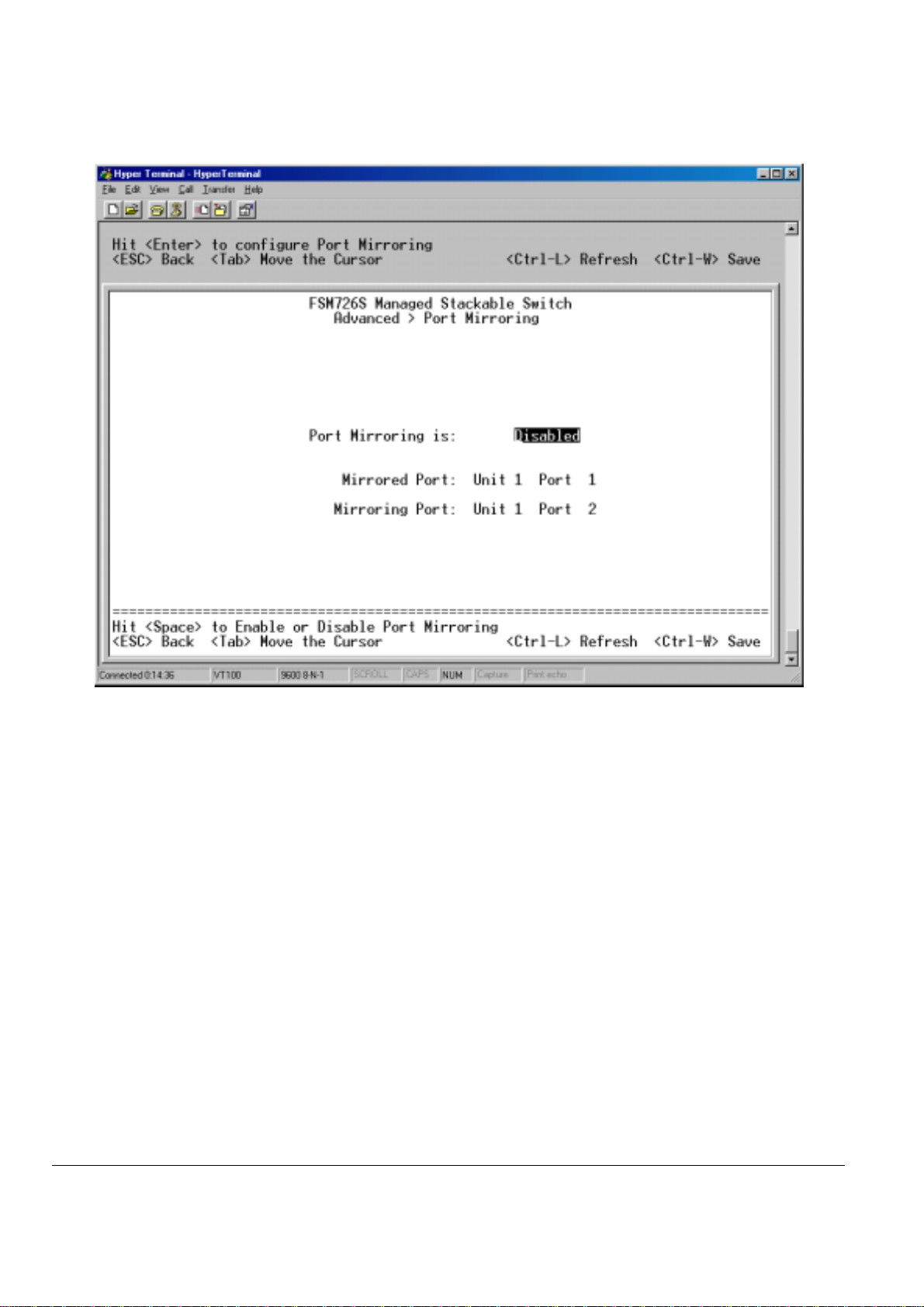
Figure 6-13: Port Mirroring
Page 48 of 121
Page 50

Main Menu> Advanced Menu> Port Trunking
Port Trunking is a feature that allows multiple links between switches to work as one virtual link or aggregate link. Trunks can be defined for similar
port types only. For example, a 10/100 port cannot form a Port Trunk with a gigabit port. For 10/100 ports, trunks can only be formed within the
same bank. A bank is ports 1 to 8, ports 9 to 16, ports 17 to 24, or port 25 and port 26 (using an FSM726S as an example), on the same switch unit.
Up to four trunks can be enabled at the same time within a stack. To set up a trunk, use the space bar to select the ports that will participate in the
trunk. Spanning Tree will treat trunked ports as a single virtual port.
Note: you must use straight-though cables for all links in the trunk. Do not use crossover cables.
Note: you must disable auto-negotiation on the ports in a trunk prior to setting up the trunk.
Figure 6-14: Port Trunking
Page 49 of 121
Page 51

Main Menu> Advance d Menu> Tr affi c P r ioritiza tio n
Port Priority allows the user to specify which ports have greater precedence in situations where traffic may be buffered in the switch due to
congestion. The ports with a setting of ‘high’ will transmit their packets before those with a ‘normal’ setting. The settings on this page only affect
ingress packets that are not already tagged for priority. To raise the priority of a given port, toggle the port’s setting from ‘normal’ to ‘high’. The
default and normal setting for a port is ‘normal’.
Figure 6-15: Traffic Prioritization
Page 50 of 121
Page 52

Main Menu> Advanced Menu> VLAN Setup
A Virtual Local Area Network (VLAN) is a means to electronically separate ports on the same switch from a single broadcast domain into separate
broadcast domains. By using VLAN, users can group by logical function instead of physical location. This switch supports up to 64 VLANs. This
switch supports static, port-based VLANs.
The VLAN Setup options are as follows:
Figure 6-16: VLANS
Page 51 of 121
Page 53

Main Menu> Advanced Menu> VLANS Setup> VLAN Admin
Up to 64 VLANs with unique ID numbers and names can be added. VLAN ID numbers must be in the range of 1-4094.
Add a VLAN
1. Type a unique numeric VLAN ID and hit Enter
2. Type a unique VLAN name and hit Enter
Remove a port or an entire VLAN
To remove an entire VLAN, just press Ctrl-X anywhere on that line
Figure 6-17: VLAN Administration
Page 52 of 121
Page 54

Main Menu> Advanced Menu> VLANS Setup> VLAN Membership
This matrix allows for real time management of up to 64 VLANs. To add a port to a VLAN, position the cursor in the desired matrix location and
toggle the options with the SPACE bar.
A ‘U’ or ‘T’ will be displayed for each port assigned to the VLAN (see Figure 6-20), where ‘U’ stands for untagged and ‘T’ for tagged. If a port is an
untagged member of a VLAN, the VLAN tag will be striped from the frame before it is sent out that port. If the port is a tagged member of a VLAN,
the VLAN tag will stay in the frame when it is sent. A ‘_’ space indicates that the port is not a member of the particular VLAN, and will not get any
traffic for that VLAN. VLAN tagging is a standard set by the IEEE to facilitate the spanning of VLANs across multiple switches. (Reference:
Appendix C and IEEE Std 802.1Q-1998 Virtual Bridged Local Area Networks)
Figure 6-18: VLAN Membership
Page 53 of 121
Page 55

Main Menu> Advanced Menu> VLANS Setup> VLAN Ports
All untagged packets entering the switch will by default be tagged with the ID specified by the port’s PVID. This screen allows you to specify the
PVID for each port. The number next to each port indicates which PVID is set for each port. Following industry standards, PVID 1 is the default
PVID
Figure 6-19: PVID Settings
Page 54 of 121
Page 56

Main Menu> Advanced Menu> Spanning Tree
This switch is compliant with IEEE802.1D Spanning Tree Protocol (STP). STP ensures that only one path at a time is active between any two
network nodes. There are maybe more than two physical path between any two nodes for redundant paths; STP ensures only one physical path is
active and the others are blocked. STP will prevent an inadvertent loop in a network, which can disable your network due to a “Broadcast storm”,
the result of a broadcast message traveling through the loop again and again.
Figure 6-20: Spanning Tree
Page 55 of 121
Page 57

Main Menu> Advanced Menu> Spanning Tree> Bridge S ettings
The following information is presented on this page:
Root Port
o
Root Port Path Cost
o
Bridge Hello Time
o
Bridge Max Age
o
Bridge Forward Delay
o
Root Bridge Priority
o
Root MAC Address
o
Switch MAC Address
o
Spanning Tree can be enabled or disabled in this screen.
Enable: There are four other tunable parameters to be addressed when enabled.
Hello Time Time between configuration messages sent by the Spanning Tree algorithm
Max Age Amount of time before a configuration message is discarded by the system
Forward Delay Amount of time system spent transitioning from the ‘learning’ to the ‘listening’ to the ‘forwarding’ states
Bridge Priority Priority setting among other switches in the Spanning Tree
Disable: Disable Spanning Tree algorithm on the system.
When Spanning tree is used in conjunction with a set of aggregated ports, otherwise known as a port trunking, Spanning Tree will treat the trunk as
a single virtual port.
Figure 6-21: Spanning Tree: Bridge Settings
Page 56 of 121
Page 58

Main Menu> Advanced Menu> Spanning Tree> P ort Settings
For the Port Settings options, you can specify Spanning Tree parameters for each port. These parameters include port priority, path cost, and
Fastlink.
Table 6-1 STP Port Setting Parameters
Parameters Range Description
Prty (Priority) 0-255 STP bases on this to determine the port to use for forwarding. The port with the lowest number
Cost
Fastlink in STP mode
When a port running the standard STP is connected, it will go through the STP negotiation (listening -> learning -> forwarding or blocking) before it
will be fully available. If a client is trying to access a server through the switch running the STP negotiation, it will not be able to connect to it
immediately. This can be a problem for some networks. Fastlink mode solves this problem by setting the port directly to forwarding mode, thus
allowing any server access request to be forwarded. Fastlink mode can cause temporary loops in your network, but the STP will find and eliminate
them. Fastlink is best used on end node ports, i.e. ports connected to PCs or servers, to avoid network loops.
1-65535 The switch uses this to determine which port is the forwarding port. All other factors equal, the
has the highest priority.
path with the lowest cost to the root bridge will be the active path.
Figure 6-22: Spanning Tree: Port Settings
Page 57 of 121
Page 59

Main Menu> Advanced Menu> MAC Address Manager
There are two advanced setup parameter can be configured here.
Static Address
o
Address Aging
o
Figure 6-23: MAC
Page 58 of 121
Page 60

Main Menu> Advanced Menu> MAC Address Manager> Addre ss A ging
The aging time is the amount of time that an entry is kept in the bridge tables prior to being purged (or aged). The range (in parentheses)
represents the minimum and the maximum values that the timer can be set.
Figure 6-24: MAC: Address Aging
Page 59 of 121
Page 61

Main Menu> Advanced Menu> MAC Address Manager> Static Addresses
The Static Addresses Table, allows the administrator to specify Media Access Control (MAC) addresses for specific ports that will not be purged
from the bridge table by the aging function.
Add an entry
Type the MAC address under the first column, and hit Enter.
o
Enter the port number, which is associated with the MAC address.
o
If all the information is correct, the new entry will appear in the list below, which is in order by port ID. Otherwise, an error message will be displayed
and the cursor will return to the MAC Address field.
Remove an entry
Tab down to the entry and press Ctrl-X. This will erase the MAC address from NVRAM. You do not need to save (hit Ctrl-W).
o
Figure 6-25: MAC: Static Address
Page 60 of 121
Page 62
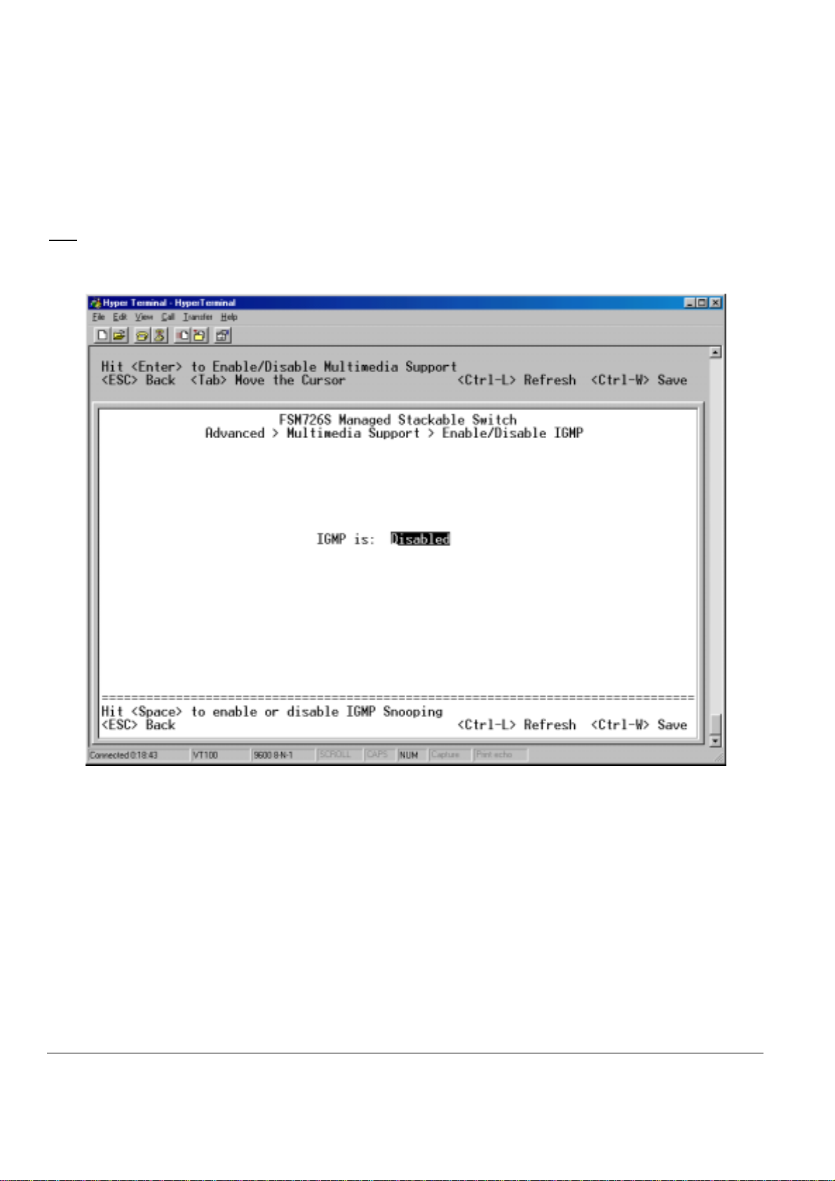
Main Menu> Advanced Menu> Enable/Disable IGMP
In networks where multimedia applications generate multicast traffic, Internet Group Multicast Protocol (IGMP) can greatly reduce unnecessary
bandwidth usage by limiting traffic forwarding that is otherwise broadcast to the whole network. Enabling IGMP will allow individual ports to detect
IGMP queries, report packets, and manage IP multicast traffic through the switch.
IGMP
Enable The system will detect IGMP queries, report packets, and manage IP multicast traffic through the switch
Disable The switch will forward traffic and disregard any IGMP requests.
Figure 6-26: Multimedia Support
Page 61 of 121
Page 63
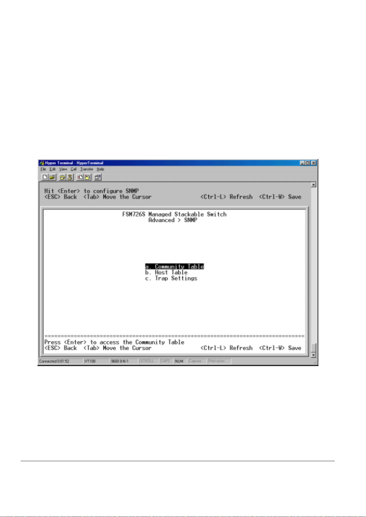
Main Menu> Advance d Menu> SNMP
You can manage this switch by SNMP from a network management station.
SNMP management features on the switch include:
o Simple Network Management Protocol (SNMP)
Support Standard MIBs:
o
• MIB II (RFC1213)
• Ethernet Interface MIB (RFC1643)
• Bridge MIB (RFC1493)
• Private Enterprise MIB
• 4-Group RMON (RFC1757)
This page has three options:
Community Table
o
Host Table
o
Trap Setting
o
Figure 6-27: SNMP Management
Page 62 of 121
Page 64

Main Menu> Advanced Menu> SNMP> Community Table
You can create up to eight different community strings with combinations of GET, SET and TRAP privileges. These community strings need to be
set prior to setting host access, as the host table depends on the existence of community strings. The public string has GET privileges by default.
Figure 6-28: SNMP Management: Community Table
Page 63 of 121
Page 65

Main Menu> Advanced Menu> SNMP> Host Table
The screen, shown in Figure 6-29, grants a host the access rights to the switch.
Host Authorization must be enabled to use the host table. Host Authorization is used as a security feature to limit people who are not listed in the
host table from accessing the switch.
If Host Authorization is enabled, the host must be added to this table, through the Console port connection in order for an end station to be access
the switch via SNMP.
Add host
Enter the host name, IP address, and the community string. Press Enter after each entry to move to the next field.
o
In the Status field, press the Spacebar until the desired Status is displayed.
o
Press Ctrl-W to save all changes.
o
Figure 6-29: SNMP Management: Host Table
Page 64 of 121
Page 66

Main Menu> Advanced Menu> SNMP> Trap Settings
Authentication Traps
When on, the system will generate an SNMP trap upon a host authorization failure. This failure occurs when a host tries to gain access to the
system but the host’s IP is not in the SNMP host table.
Figure 6-30: SNMP Management: Trap Settings
Page 65 of 121
Page 67

Page 66 of 121
Page 68

CHAPTER 7: WEB MANAGEMENT ACCESS
Your NETGEAR Model FSM726S or FSM750S Managed Stackable Switch provides a built-in browser interface that lets you configure and manage
it remotely using a standard Web browser such as Microsoft Internet Explorer or Netscape Navigator. This interface also allows for system
monitoring of the Switch. The ‘help’ page will cover many of the basic functions and features of the switch and it’s web interface.
When you configure the switch for the first time from the console, you can assign an IP address and subnet mask to the switch. Thereafter, you can
access the switch’s Web interface directly using your Web browser by entering the switch’s IP address into the address bar. In this way, you can
use your Web browser to manage the switch from a central location, just as if you were directly connected to the switch’s console port. Figure 7-1
shows this management method.
Figure 7-1: Web Management Method
Web Management requires either Microsoft Internet Explorer 5.0 or later or Netscape Navigator 6.0 or later.
Web Pages
Before connecting to the switch via a web browser (i.e. Netscape Navigator), a login screen will appear prompting for an administrator password (if
the password protection is enabled). The User Name will always be ‘admin’. Enter the password to access the switch’s management mode. Once
the password is entered correctly, the front page will appear.
Figure 7-2: Password
Note: If password protection is enabled (using the console) without setting your own password, the default password is ‘1234’.
Page 67 of 121
Page 69

There are 6 menu options available:
o
o
o
o
o
o
System
Status
Set-up
Tools
Security
Advanced
There is a help menu in the top of right side of screen; you can click the ‘help’ or the question mark to read the help menu.
The help menu contains:
Web-Based Management Introduction to the Web management features.
Device Management Introduction of the basic icons and management of the device
Interface Operations Describes Web browser requirements, and common commands
Product Overview Describes supported SNMP and Web management features
Summary of Features Feature List
Within the various browser interface pages, there are several buttons that you can use. Their names and functions are below:
Reload: Pulls that screen’s data from current values on the system
Apply: Submits change request to system and refreshes screen data
Add: Adds new entries to table information and refreshes screen data
Remove: Removes selected entries from table and refreshes screen data
Reset: Reset system, the action is equivalent to power off /on.
Restore: Restore the system factory default value, except password and IP.
Query: System will retrieve the useful information in database.
Page 68 of 121
Page 70

System
This is a welcome page, which displays system information, such as:
These parameters are not editable from this screen. They can be modified in the Set Up> System Configuration page.
System Description
o
o System Name
o System Contact
o System Location
o MAC Address
IP Address
o
Subnet Mask
o
Default Gateway
o
Software Version
o
Figure 7-3: System
Page 69 of 121
Page 71

Status
The Status page contains 5 menus:
Status > Switch Statistics
The Switch Statistics Chart allows you to compare one type of statistic across all the ports.
Switch Statistics Chart
There are 24 kinds of Statistics that you can review on this screen:
Inbound Octet Rate: Received Byte per second.
Inbound Unicast Packet Rate: Received Unicast packet per second.
Inbound Non-unicast Packet rate: Received Non-unicast packet per second.
Inbound Discard Rate: Received and is discarded packet per second.
Inbound Error Rate: Received error packet per second.
Outbound Octet Rate: Transmitted byte per second.
Outbound Unicast Packet Rate: Transmitted unicast packet per second.
Outbound Non-unicast Packet rate: Transmitted non-unicast packet per second.
Outbound Discard Rate: Transmitted and is discarded packet per second.
Outbound Error Rate: Transmitted error packet per second.
Ethernet Undersize Packet Rate: Less than 64byte length packet per second.
Ethernet Oversize Packet Rate: More than 1518byte length packet per second
Inbound Octets: Received bytes
Inbound Unicast Packets: Received unicast packet
Inbound Non-unicast Packets: Received non-unicast packet
Inbound Discards: Received and is being discarded packet.
Inbound Errors: Received and is a error packet
Outbound Octets: Transmitted byte
Outbound Unicast Packets: Transmitted unicast packet
Outbound Non-unicast Packets: Transmitted non-unicast packet.
Outbound Discards: Transmitted and is being discarded packet
Outbound Errors: Transmitted and is an Error packet.
Ethernet Undersize Packets: Less than 64byte length packet
Ethernet Oversize Packets: more than 1518 byte length packet.
Switch Statistics
o
o Port Statistics
o Port Settings
o MAC Address Table
o Error Chart
Statistics The type of system data to be monitored
o
Refresh Rate The time interval between automatic refreshes (5, 10, 15, 30 seconds)
o
Color The color setting for the chart
o
Page 70 of 121
Page 72

Figure 7-4: Statistics: Switch Statistics
Page 71 of 121
Page 73

Status > Port Statistics
The Port Statistics Chart shows all the statistic types for one port over time.
Port The port on which data will be monitored
o
Refresh Rate The time interval between automatic refreshes
o
Color The color setting for the data
o
There are 12 kinds of Port Statistics
Inbound Octets: Received bytes
Inbound Unicast Packets: Received unicast packet
Inbound Non-unicast Packets: Received non-unicast packet
Inbound Discards: Received and is being discarded packet.
Inbound Errors: Received and is a error packet
Outbound Octets: Transmitted byte
Outbound Unicast Packets: Transmitted unicast packet
Outbound Non-unicast Packets: Transmitted non-unicast packet.
Outbound Discards: Transmitted and is being discarded packet
Outbound Errors: Transmitted and is an Error packet.
Ethernet Undersize Packets: Less than 64byte length packet
Ethernet Oversize Packets: more than 1518 byte length packet.
Figure 7-5: Statistics: Port Statiscis
Page 72 of 121
Page 74
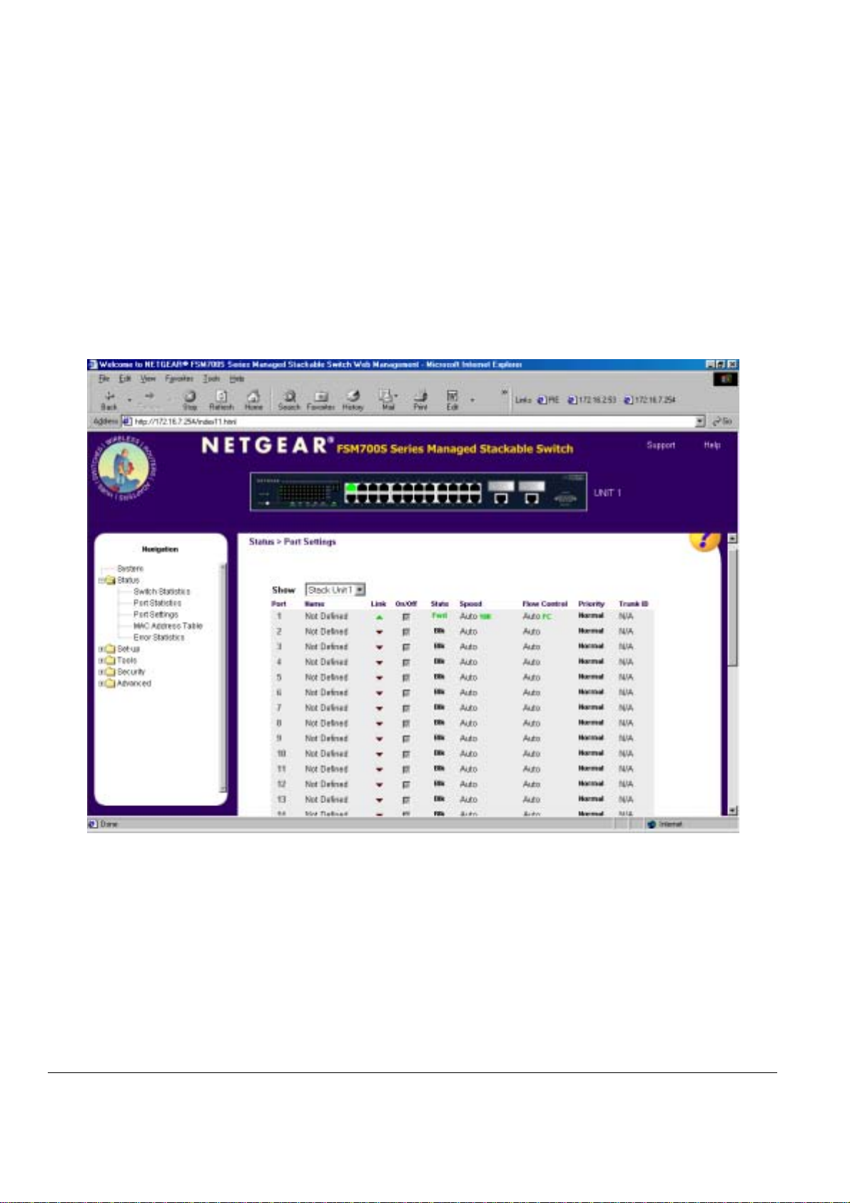
Status > Port Settings
This page displays the port settings. To configure the ports, go to the ‘Port Configuration’ under the ‘Set-up’ sub menu.
Port Number: The port number on the switch
o
Port Name: The name of the port. This is a user-defined label.
o
Link Status: A green triangle pointing up indicates a valid link, while a red triangle pointing down indicates no link.
o
On/Off: Indicates if the port is enabled or disabled by the Administrator.
o
State: This refers to the Spanning Tree state of the port. Ports will be Blocking (Blk), Listening (Lis), Learning (Lrn),
o
Speed: Indicates the speed and duplex for the port. The possible entries are Auto-negotiation (Auto); 10 Mbps half duplex
o
Flow Control: Indicates whether Flow Control support is set for automatic (Auto) or off (Disabled)
o
Priority Indicates if the port is set to high priority or normal priority. This is an advanced feature that is configured under
o
Trunk ID Indicates if the port is a member of a trunk by showing the ID number of the trunk. This is an advanced feature that
o
Forwarding (Fwd) or Disabled (Dis).
(10M Half); 10 Mbps full duplex (10M Full); 100 Mbps half duplex (100M Half); or 100 Mbps full duplex (100M Full).
Traffic Prioritization
is configured under Port Trunking
Figure 7-6: Port Configuration: Port Settings
Page 73 of 121
Page 75

Status > MAC Address Table
The MAC Address Table is a dynamic address lookup table allows you to view the dynamic MAC addresses that are currently in the address
database. When addresses are in the database, the packets intended for those addresses are forwarded directly to those ports. You can filter the
displayed addresses by port, VLAN, and/or MAC address by checking those fields.
Figure 7-7: Status Manager: MAC Address Table
Page 74 of 121
Page 76

Status > Error Statistics
The Error Statistics Graph allows you to chart one type of statistic for any combination of ports. In the case of the Error Statistics Graph, the chart
will present data across time so that fluctuations in time can be easily seen. All charts have a maximum ceiling of more than 2.1 billion
(2,147,483,647). You can see the value of each bar or line in the chart by clicking on the bar. The following will outline the settings for each type of
graph.
When all of the variables are set, click Draw.
Statistics The type of system errors to be monitored
o
Refresh Rate The time interval between automatic refreshes (5,10,15, 30 seconds)
o
Port Selection The port for data to be monitored
o
Figure 7-8: Statistics: Error Statistics
Page 75 of 121
Page 77
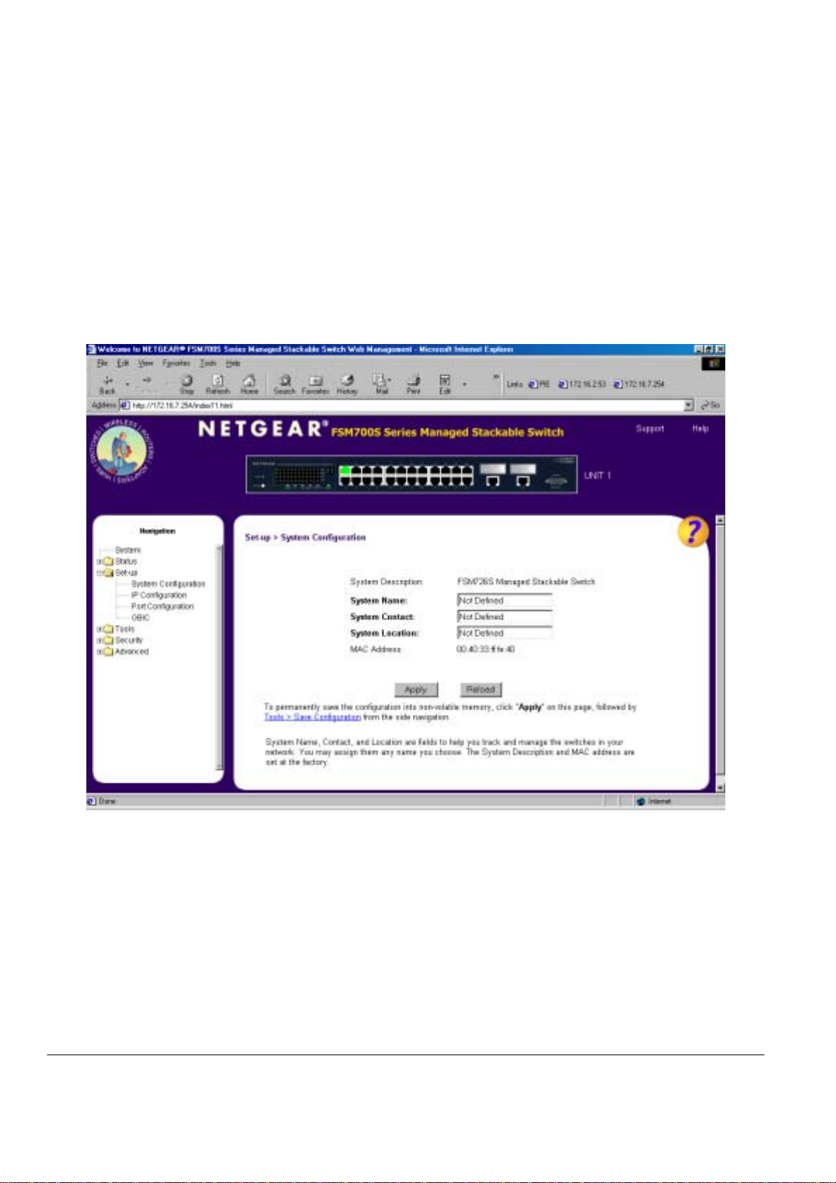
Set-up
There are four kinds of configuration in the Setup page:
Set-up> System Configuration
This page will allow access to the system information parameters.
System Configuration
o
o IP Configuration
o Port Configuration
o Gigabit Port Configuration (GBIC)
o Enter System Name, System Contact, System Location
o Click Apply to change the System Configuration
Save Configuration to NVRAM and reset the system to implement the changes (Tools > Save Configuration)
o
Figure 7-9: System Configuration
Page 76 of 121
Page 78
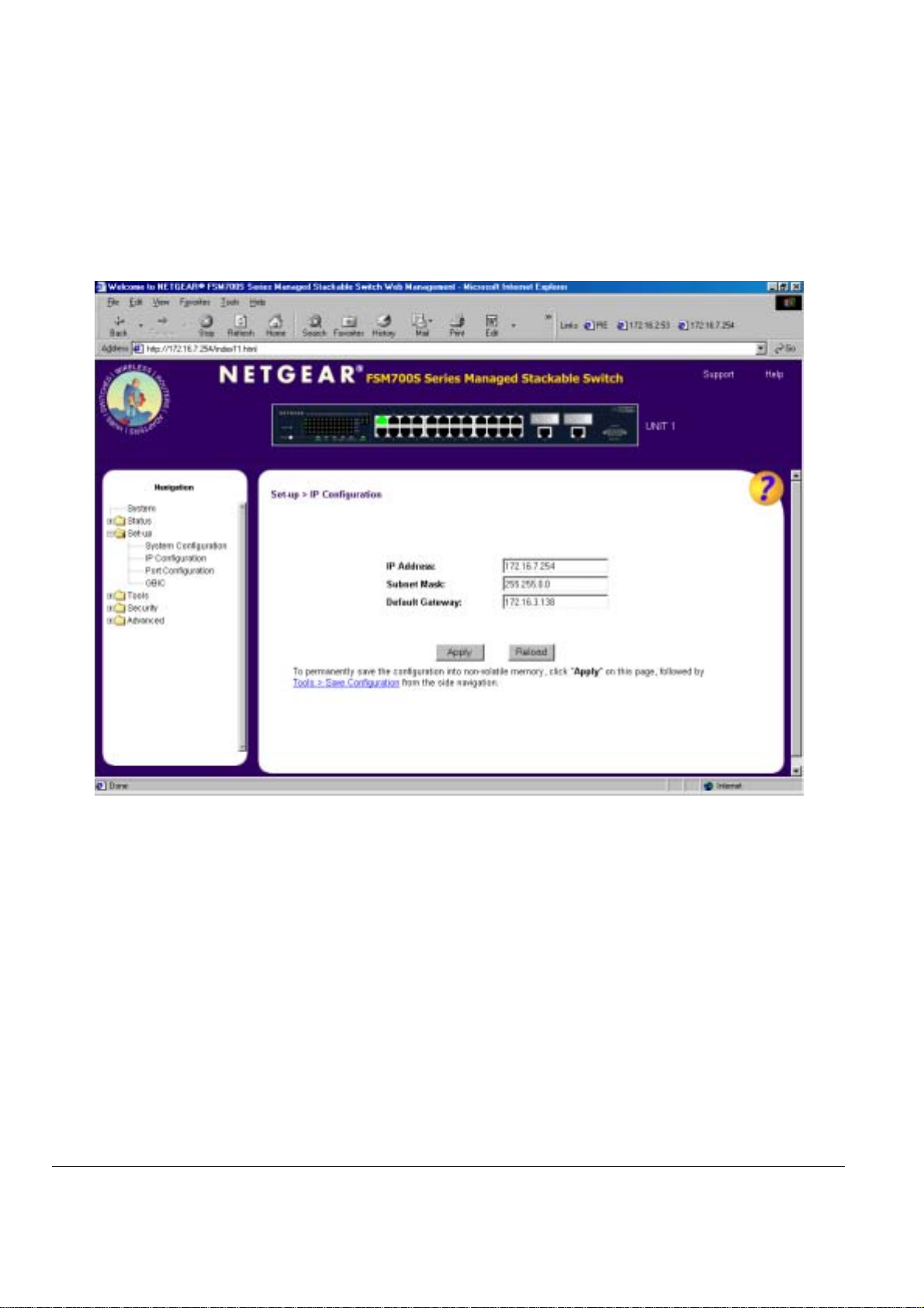
Set-up> IP Configura tion
You can manage this switch over the network using its IP address, as set in this menu.
There are three tunable parameters to be set by the system administrator.
Enter site-specific IP address, Gateway address and Net mask
o
Click Apply to change the IP settings
o
Save Configuration to NVRAM and reset the system to implement the changes (Tools > Save Configuration)
o
Figure 7-10: System Manager: IP Configuration
Page 77 of 121
Page 79
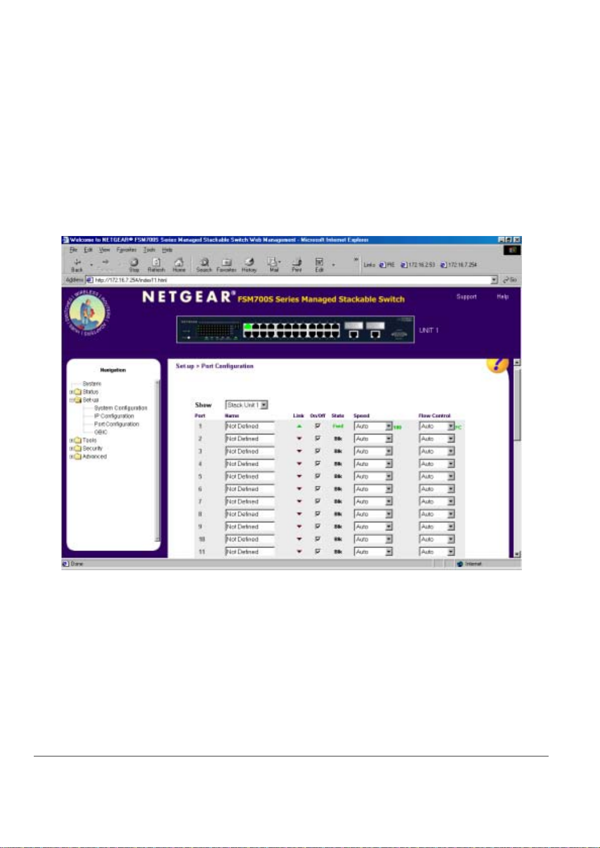
Set-up> Port Configuration
You can configure the status per port at ‘Port Configuration’ menu.
Port Number: The port number on the switch
o
Port Name: The name of the port. This is a user-defined label.
o
Link Status: A green triangle pointing up indicates a valid link, while a red triangle pointing down indicates no link.
o
On/Off: Indicates if the port is enabled or disabled by the Administrator.
o
State: This refers to the Spanning Tree state of the port. Ports will be Blocking (Blk), Listening (Lis), Learning (Lrn),
o
Speed: Indicates the speed and duplex for the port. The possible entries are Auto-negotiation (Auto); 10 Mbps half duplex
o
Flow Control: Indicates whether Flow Control support is set for automatic (Auto) or off (Disabled)
o
Forwarding (Fwd) or Disabled (Dis).
(10M Half); 10 Mbps full duplex (10M Full); 100 Mbps half duplex (100M Half); or 100 Mbps full duplex (100M Full).
Figure 7-11: Setup: Port Configuration
Page 78 of 121
Page 80

Set-up> GBIC
This page allows the user to choose the port type of the gigabit ports. The default is copper (RJ-45). If the user chooses to use a GBIC, the setting
on this page must be appropriately set.
Note: enabling the GBIC connector for a Gigabit Ethernet port disables the built-in 1000BASE-T port.
Figure 7-12: Setup: GBIC
Page 79 of 121
Page 81

Tools
The Tools page contains functions to maintain your switch. There is a firmware upgrade; the means to save current settings to non-volatile
memory (NVRAM); as well as software reset mechanism. The page has three sub-pages:
o Software Upgrade
o Save Configuration
o Device Reset
Tools> Software Upgrad e
In the Software Upgrade screen, the system can be configured to download and boot from a new image from the network. Please refer to Chapter
5 when updating software. Choose the method for the next system boot process: 'Net' will boot from the network, 'Net and Save' will boot from the
network and permanently save the retrieved boot image in the switch, 'Last Saved' will boot from the boot image last saved in non-volatile memory
in the switch. For booting from the network, supply the TFTP server IP address and boot image file name, then select 'Apply'.
Net option
This option allows the user to try out a new image before upgrading. It requires a TFTP filename and a server IP address to retrieve the specified
image from the given IP address. The new image will not overwrite the one in non-volatile memory. (This is the default setting. See Figure 7-13)
Net & save
This option requires the same setup as the Net option, i.e. TFTP server and a new image. However, it copies the image to non-volatile memory and
then the system boots from non-volatile memory.
Last Saved
The system will boot from non-volatile memory. This option will automatically show up after the ‘Net & save’ option is selected and the unit is reset.
option
option
Figure 7-13: Software Upgrade
Page 80 of 121
Page 82

Tools> Save Configuration
After making any changes to the screens within the Web Interface, you can save the changed settings to NVRAM. If changes are not saved to
NVRAM, then they will be lost during the next switch reset or reboot.
Restore the factory configuration by selecting 'Restore'.
: network IP settings (i.e. IP address, Gateway Address, Network Mask) will not be affected by the Restore command.
Note
Figure 7-14: Save Configuration
Page 81 of 121
Page 83

Tools> Device Reset
In this screen the user can reset (power cycle) the switch. This is primarily used to upgrade the firmware or restore defaults. Reset the switch by
selecting 'Reset'
Figure 7-15: Device Reset
Page 82 of 121
Page 84

Security
Passwords
The password entered is encrypted on the screen and will display as a sequence of asterisks (*). The user name is ‘admin’ and cannot be
changed. The user name and password are case sensitive.
Note: If you have enabled password protection without setting your own password, the default password is ‘1234’.
Enable the password protection
o
Type the new administrator password in the New password field
o
Type the same password in the Verify field
o
Click Apply to activate the new password
o
Figure 7-16: System Manager: Password Admin
Page 83 of 121
Page 85

Advanced
The Advanced page allows professional users to operate more complicated features of the device, which include VLAN, Spanning Tree, Port
Trunking, Multimedia support (IGMP), traffic prioritization, SNMP, and port mirroring. These features are powerful and can degrade or damage a
network’s performance if improperly used.
o Port Mirroring: Users can designate a port for monitoring traffic from one or more other ports or of a single VLAN configured on the switch.
The switch monitors the network activity by copying all traffic from the specified monitoring sources to the designated monitoring port, to
which a network analyzer can be attached.
Port Trunking: a feature that allows multiple links between switches to work as one virtual link (aggregate link). Trunks can be defined for
o
similar port types only. For example, a 10/100 port cannot form a Port Trunk with a gigabit port. For 10/100 ports, trunks can only be
formed within the same bank. A bank is a set of eight ports. Up to four trunks can be operating at the same time. Toggle the ports to the
correct trunk number to set up a trunk. After clicking Apply, the trunk will be enabled. Spanning Tree will treat trunked ports as a single
virtual port.
Multimedia Support (IGMP): The Internet Group Management Protocol (IGMP) is an Internet protocol that provides a way for network
o
devices to report multicast group membership to adjacent routers.
Traffic Prioritization (CoS): Class of Service (CoS), also referred to as Quality of Service (QoS), is a way of managing traffic in a network,
o
by treating different types of traffic with different levels of service priority. Higher priority traffic gets faster treatment during times of
switch congestion.
VLANs: A Virtual Local Area Network (VLAN) is a means to electronically separate ports on the same switch from a single broadcast
o
domain into separate broadcast domains. By using VLAN, users can group by logical function instead of physical location. There are 64
VLAN supported on this switch.
Spanning Tree Protocol (STP) ensures that only one path at a time is active between any two network nodes. There are maybe more
o
than two physical path between any two nodes for redundant paths; STP ensures only one physical path is active and the others are
blocked. STP will prevent an inadvertent loop in a network, which can disable your network due to a “Broadcast storm”, the result of a
broadcast message traveling through the loop again and again.
o MAC: MAC address table management
o
Advanced>Disable Advance Alerting: To prevent the accidental use, there are warnings that appear when an advanced feature is
selected. This screen allows experienced users might want to bypass these warnings during a browser session. The warning
will be re-activate at the next browser session in case another, less experienced user is accessing the switch
Figure 7-17: Advanced > Disable Advanced Alerting
Page 84 of 121
Page 86

Advanc e d > P o rt Mi rr or i n g
Port mirroring is a feature to help in the debugging of a network. This web interface page allows the enabling or disabling of port mirroring and the
setting of source and monitor ports. The monitor port will show a copy of every packet that arrives or leaves the source port.
Figure 7-18: Port Mirroring
Page 85 of 121
Page 87

Advanced > Port Trunking
Port Trunking is a feature that allows multiple links between switches to work as one virtual link (aggregate link). Trunks can be defined for similar
port types only. For example, a 10/100 port cannot form a Port Trunk with a gigabit port. For 10/100 ports, trunks can only be formed within the
same bank. A bank is a group of 8 10/100 ports or 2 gigabit ports, for example, ports 1 to 8, ports 9 to 16, ports 17 to 24, or port 25 and port 26, on
the same switch unit. Up to four trunks can be enabled at the same time within a stack. To set up a trunk, use the space bar to select the ports
that will participate in the trunk. Spanning Tree will treat trunked ports as a single virtual port.
Figure 7-19: Port Trunking
Page 86 of 121
Page 88
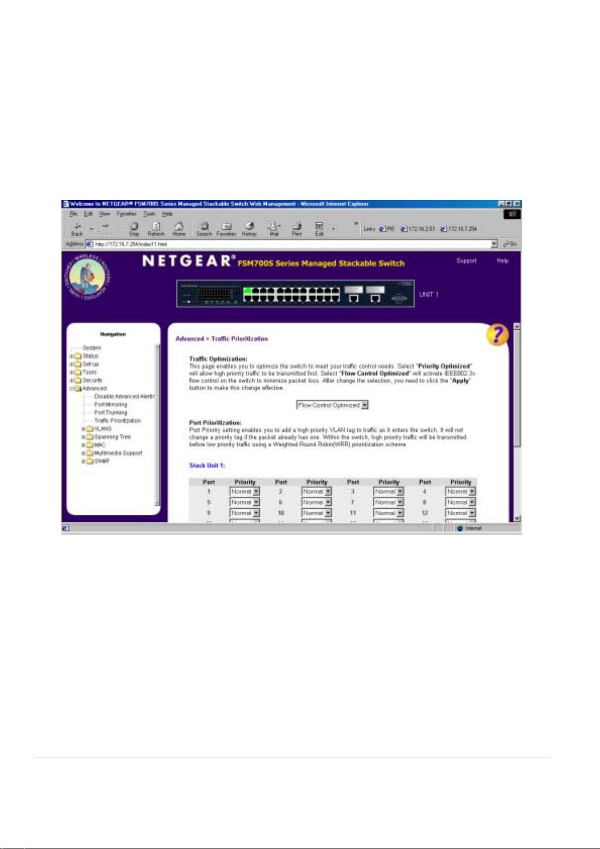
Advanced > Traffic Prioritization
Port Priority allows the user to specify which ports have greater precedence in situations where traffic may be buffered in the switch due to
congestion. The ports with a setting of ‘high’ will add a tag to incoming packets that identify them as having higher priority. If congestion at an
outgoing port occurs, these higher priority packets will be transmitted before those with a ‘normal’ tag. If a packet arrives at the swtich with a
priority tag, the swtich will not change it. The tags used to track packet priority are the standard VLAN tag, which will be removed from the packet
before it leaves the switch if that exiting port is designated a VLAN untagged port.
To raise the priority of a given port, switch the port’s setting from ‘normal’ to ‘high’. The default and normal setting for a port is ‘normal’.
Figure 7-20: Traffic Priortization Settings
Page 87 of 121
Page 89

Advanced> VLAN
VLANs: A Virtual Local Area Network (VLAN) is a means to electronically separate ports on the same switch from a single broadcast domain into
separate broadcast domains. By using VLAN, users can group by logical function instead of physical location. There are 64VLAN supported on this
switch. This switch supports static, port-based VLANs.
A ‘U’ or ‘T’ will be displayed for each port assigned to the VLAN (see Figure 7-21), where ‘U’ stands for untagged and ‘T’ for tagged. If a port is an
untagged member of a VLAN, the VLAN tag will be striped from the frame before it is sent out that port. If the port is a tagged member of a VLAN,
the VLAN tag will stay in the frame when it is sent. A ‘_’ space indicates that the port is not a member of the particular VLAN, and will not get any
traffic for that VLAN. The VLAN tagging option is a standard set by the IEEE to facilitate the spanning of VLANs across multiple switches
(Reference: Appendix C and IEEE Std 802.1Q-1998 Virtual Bridged Local Area Networks).
From this menu, you can create a new VLAN, add new ports to an existing VLAN, remove ports from an existing VLAN or, delete a VLAN.
Create a new VLAN Group
o Under the ‘Show VLAN’ drop down menu, select ‘Add a new VLAN’.
Enter the VLAN Id and name in the provided fields.
o
Add VLAN members if so desired. (See below).
o
Click Apply.
o
Delete a VLAN Group
Check the Remove VLAN box for the VLAN you want to remove.
o
Click Apply.
o
Add a port to a VLAN Group
o Under the ‘Show VLAN’ drop down menu, select the VLAN you want to edit.
o Click the box below the port number on the line of the VLAN so that a ‘T’ (tagged) or ‘U’ (untagged) appears.
o Click Apply.
Remove a port from a VLAN Group
Click the box again until a blank box appears. This will remove VLAN membership from the port.
o
Click Apply.
o
Page 88 of 121
Page 90

Figure 7-21: VLANS: VLAN’s and Primary VLAN
Advanced> VLAN> VLAN Port
All untagged packets entering the switch will by default be tagged as specified by the port’s Primary VLAN Identification (PVID). This screen allows
you to specify the PVID for each port.
Page 89 of 121
Page 91

Figure 7-22: VLAN: VLAN Port Settings
Page 90 of 121
Page 92

Advanced> Spanning Tree
Spanning Tree Protocol (STP) ensures that only one path at a time is active between any two network nodes. There are maybe more than two
physical path between any two nodes for redundant paths; STP ensures only one physical path is active and the others are blocked. STP will
prevent an inadvertent loop in a network, which can disable your network due to a “Broadcast storm”, the result of a broadcast message traveling
through the loop again and again.
There are two sub-page of Spanning Tree configuration:
Bridge Settings
o
Port Settings
o
Page 91 of 121
Page 93
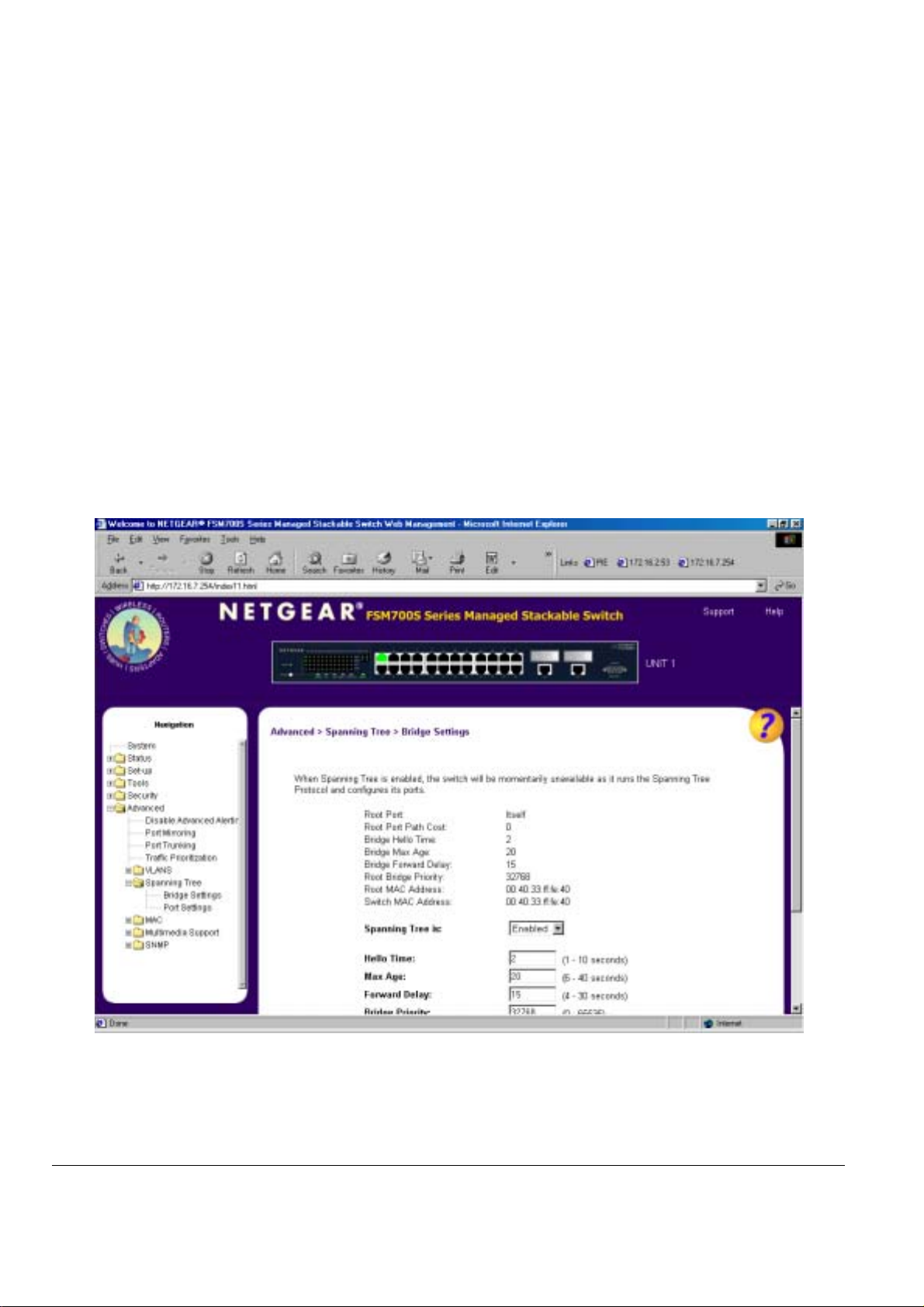
Advanced> Spanning Tree > Bridge Settings
The following information is presented on the this page:
Root Port
o
Root Port Path Cost
o
Bridge Hello Time
o
Bridge Max Age
o
Bridge Forward Delay
o
Root Bridge Priority
o
Root MAC Address
o
Switch MAC Address
o
Spanning Tree can be enabled or disabled in this screen.
Enable: There are four other tunable parameters to be addressed when enabled.
Hello Time Interval between configuration messages sent by the Spanning Tree algorithm
Max Age Amount of time before a configuration message is discarded by the system
Forward Delay Amount of time system spends in ‘learning’ and ‘listening’ states
Bridge Priority Priority setting among other switches in the Spanning Tree
Disable: Disable Spanning Tree algorithm on the system.
When Spanning tree is used in conjunction with a set of aggregated ports, also known as a port trunking, Spanning Tree will treat the trunk as a
single virtual port.
Figure 7-23: Spanning Tree: Bridge Settings
Page 92 of 121
Page 94

Advanced> Spanning Tree > Port Settings
For the Port Settings options, you can specify Spanning Tree parameters for each port. The Spanning Tree parameters include port priority, path
cost, and Fastlink.
Table 7-1. STP Port Setting Parameters
Parameters Range Description
Prty (Priority) 0-255 STP bases on this to determine the port to use for forwarding. The port with the lowest number
Cost
1-65535 The switch uses this to determine which port is the forwarding port. All other factors equal, the
has the highest priority.
path with the lowest cost to the root bridge will be the active path.
Fastlink in STP mode
When a port running the standard STP is connected, it will go through the STP negotiation (listening -> learning -> forwarding or blocking) before it
will be fully available. If a client is trying to access a server through the switch running the STP negotiation, it will not be able to connect to it
immediately. This can be a problem for some networks. Fastlink mode solves this problem by setting the port directly to forwarding mode, thus
allowing any server access request to be forwarded. Fastlink mode can cause temporary loops in your network, but the STP will eliminate them.
Fastlink is best used on end node ports, i.e. ports connected to PCs or servers, to avoid network loops.
Figure 7-24: Spanning Tree: Port Settings
Page 93 of 121
Page 95

Advanced> MAC
There are two kind of configuration in advanced MAC setup:
o Aging Time
o Static Address
Advanced> MAC> Address Aging
Aging Time is a variable that must be configured. Its purpose is to determine the amount of time an entry is held in the forwarding tables while no
activity occurs from that address. Entries should be removed to update the table for MAC addresses that have moved or are turned off.
The default value is set to 300 seconds (5 minutes).
o The administrator may change this value to any value between 10 and 1,000,000 seconds.
o After changing the value, click ‘Apply’
Figure 7-25: MAC > Address Aging
Page 94 of 121
Page 96
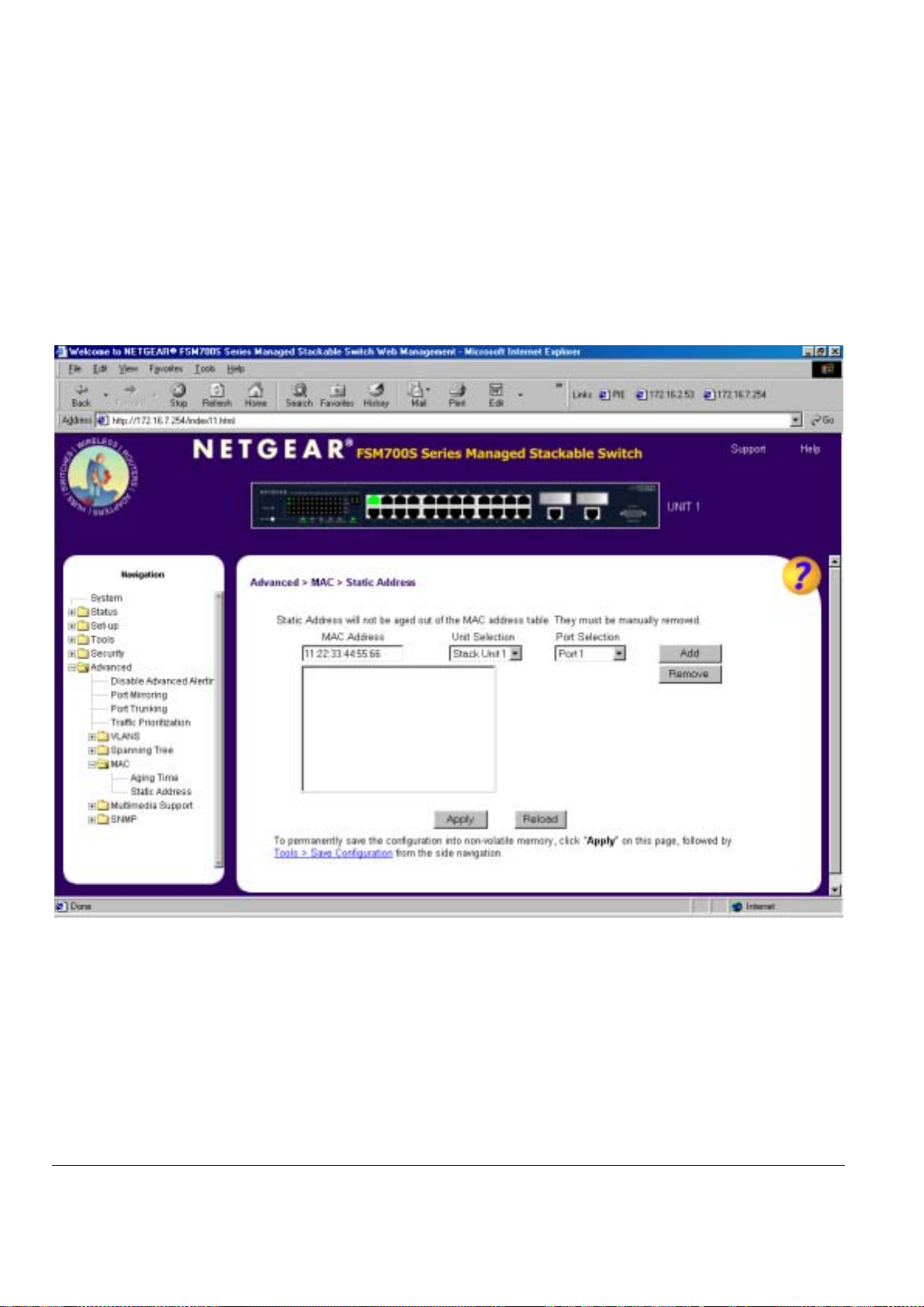
Advanced> MAC> Static Addresses
Any system, whose MAC address and the port number are listed in this screen, will not be purged from the system’s forwarding table by the aging
process.
Add a new entry
Remove an exist entry
Enter the MAC address and port in the appropriate boxes
o
Click Add
o
o Highlight that entry in the table, by clicking on the MAC address
o Choose Remove
Figure 7-26: MAC > Static Addresses
Page 95 of 121
Page 97

Advanced> Multimedia Support>Enable/ Disable IGMP
In networks where multimedia applications generate multicast traffic, Internet Group Multicast Protocol (IGMP) can greatly reduce unnecessary
bandwidth usage by limiting traffic forwarding that is otherwise broadcast to the whole network. Enabling IGMP will allow individual ports to detect
IGMP queries, report packets, and manage IP multicast traffic through the switch.
IGMP
Enable The system will detect IGMP queries, report packets, and manage IP multicast traffic through the switch
Disable The switch will forward traffic and disregard any IGMP requests.
Figure 7-27: Multimedia Support > Enable/Disable IGMP
Page 96 of 121
Page 98

Figure 7-28: Multimedia Support > Static Multicast Groups
Page 97 of 121
Page 99

Advanced> SNMP
Users can manage this switch by SNMP from a network management station.
SNMP management features on the switch include:
o Simple Network Management Protocol (SNMP)
Support Standard MIBs:
o
This page has three SNMP Settings:
o Community Table
o
o
Advanced> SNMP> Community Table
The administrator can create up to eight different community strings with combinations of GET, SET and TRAP privileges. These community
strings need to be set prior to setting host access, as the host table depends on the existence of community strings. The public string has GET
privileges by default.
• MIB II (RFC1213)
• Ethernet Interface MIB (RFC1643)
• Bridge MIB (RFC1493)
• Enterprise MIB
• 4-Group RMON (RFC1757)
Host Table
Trap Setting
Figure 7-29: SNMP Management: Community Table
Page 98 of 121
Page 100

Advanced> SNMP> Host Table
The SNMP Host Table screen allows you to add and remove hosts from access rights that have been granted to community groups. The
permissions GET, SET and TRAP are assigned to a community name and then these permissions are assigned to individual machines by adding
those machines and their IP address to the appropriate community string. Host Authorization can be Enabled or Disabled.
If Host Authorization is enabled, the host must be added to this table, through the Console port connection in order for an end station to be access
the switch via SNMP.
Figure 7-30: SNMP Management > Host Table
Page 99 of 121
 Loading...