

Netgate XG-7100-1U Product Manual

Product Manual
XG-7100-1U
Netgate
Aug 08, 2018

CONTENTS
1 Quick Start Guide 2
1.1 I/O Ports . . . . . . . . . . . . . . . . . . . . . . . . . . . . . . . . . . . . . . . . . . . . . . . . . 2
1.2 XG-7100 Switch Overview . . . . . . . . . . . . . . . . . . . . . . . . . . . . . . . . . . . . . . . 4
1.3 Getting Started . . . . . . . . . . . . . . . . . . . . . . . . . . . . . . . . . . . . . . . . . . . . . . 23
1.4 Connecting to Console Port . . . . . . . . . . . . . . . . . . . . . . . . . . . . . . . . . . . . . . . 33
1.5 Additional Resources . . . . . . . . . . . . . . . . . . . . . . . . . . . . . . . . . . . . . . . . . . . 39
1.6 Warranty and Support Information . . . . . . . . . . . . . . . . . . . . . . . . . . . . . . . . . . . . 39
1.7 Safety and Legal . . . . . . . . . . . . . . . . . . . . . . . . . . . . . . . . . . . . . . . . . . . . . 40
2 High Availability 48
2.1 High Availability Prerequisites . . . . . . . . . . . . . . . . . . . . . . . . . . . . . . . . . . . . . . 48
2.2 Configuring a HA Cluster . . . . . . . . . . . . . . . . . . . . . . . . . . . . . . . . . . . . . . . . 51
2.3 Components of a High Availability Cluster . . . . . . . . . . . . . . . . . . . . . . . . . . . . . . . 58
2.4 Testing High Availability . . . . . . . . . . . . . . . . . . . . . . . . . . . . . . . . . . . . . . . . . 59
2.5 Troubleshooting High Availability . . . . . . . . . . . . . . . . . . . . . . . . . . . . . . . . . . . . 61
2.6 Upgrading pfSense on a High Availability Cluster . . . . . . . . . . . . . . . . . . . . . . . . . . . 64
3 Reinstalling pfSense 66
4 BIOS Flash Procedure 68
4.1 Update via the GUI . . . . . . . . . . . . . . . . . . . . . . . . . . . . . . . . . . . . . . . . . . . . 68
i

Product ManualXG-7100-1U
Thank you for your purchase of the pfSense® XG-7100 1U System. This Netgate appliance provides a powerful,
reliable, cost-effective solution.
Quick Start Guide
The Quick Start Guide covers the first time connection procedures and will provide you with the information you need
to get your appliance up and running.
References
• High Availability
• Reinstalling pfSense
• BIOS Flash Procedure
• pfSense Documentation
CONTENTS 1
CHAPTER
ONE
QUICK START GUIDE
This Quick Start Guide covers first time connection procedures for a new appliance.
Table of Contents
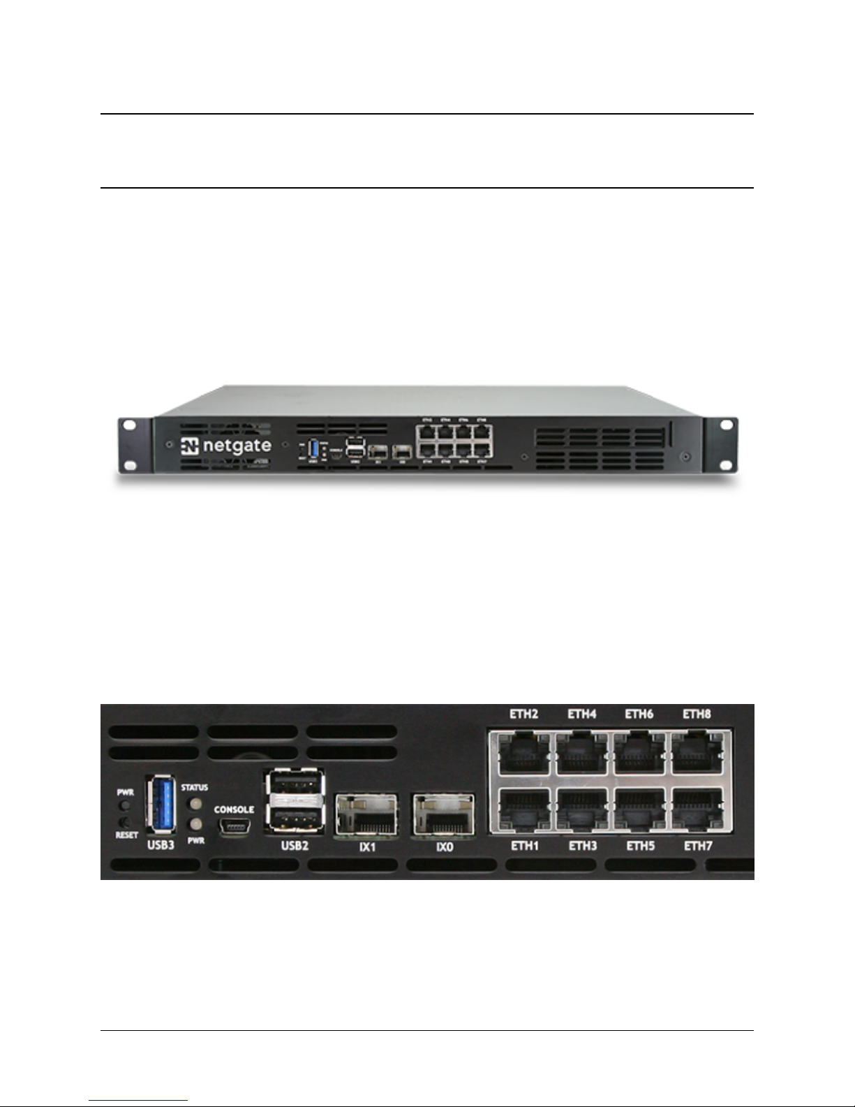
1.1 I/O Ports
Ports are assigned as pictured.
2
Product ManualXG-7100-1U
1.1.1 Ethernet Ports
Interface Name Port Name Port Type Port Speed
WAN ETH1 RJ-45 1 Gbps
LAN ETH2-ETH8 RJ-45 1 Gbps
OPT1 IX0 SFP+ 10 Gbps
OPT2 IX1 SFP+ 10 Gbps
Note: ETH1-8 are switched ports sharing 5 Gbps (2x 2.5 Gbps) to the Intel SoC. These ports can be isolated as an
independent interface with the configuration of VLAN tagging as shown in XG-7100 Switch Overview.
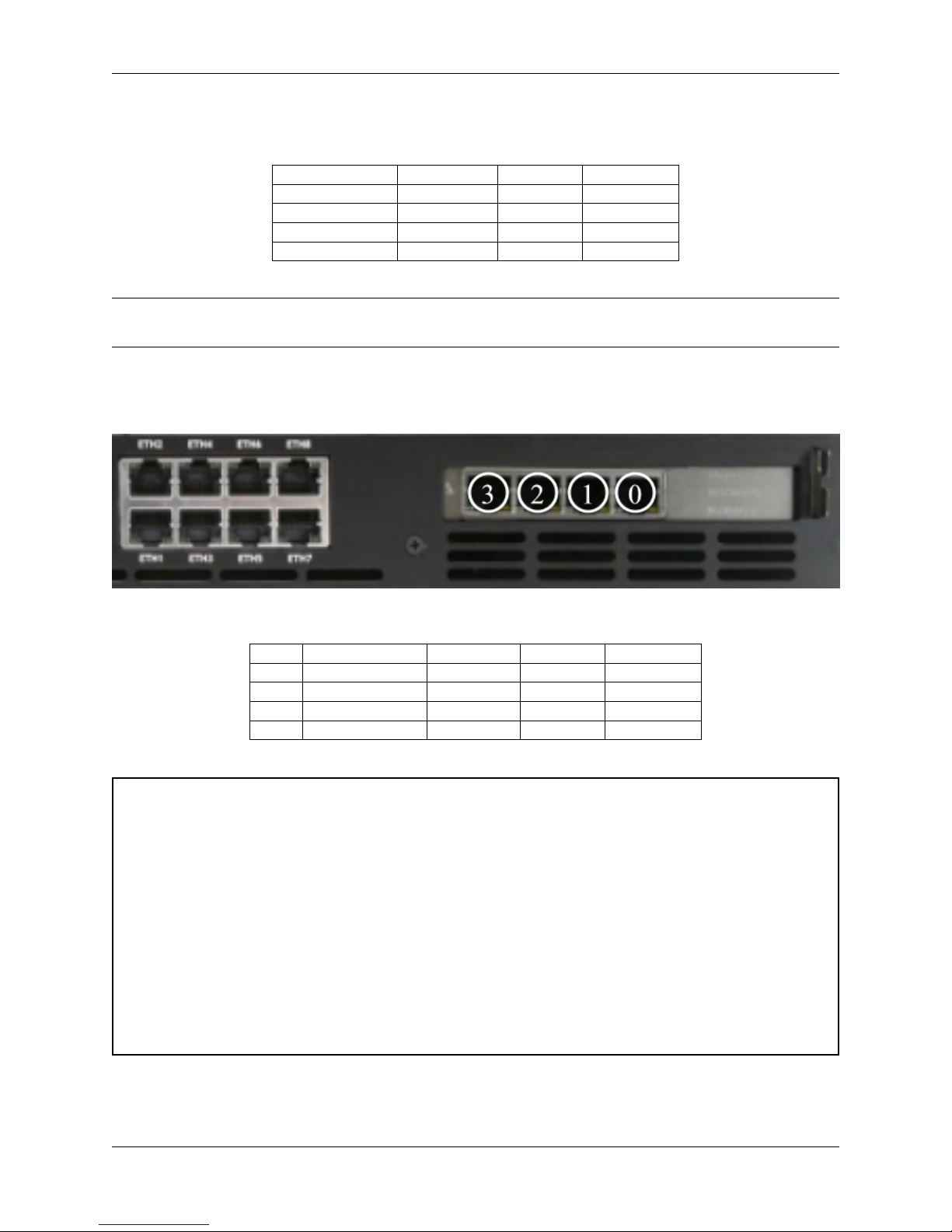
1.1.2 Optional 4-Port Intel 1 Gb Ethernet Expansion Card
Ports are assigned as numbered.
Num Interface Name Port Name Port Type Port Speed
0 OPT3 igb0 RJ-45 1 Gbps
1 OPT4 igb1 RJ-45 1 Gbps
2 OPT5 igb2 RJ-45 1 Gbps
3 OPT6 igb3 RJ-45 1 Gbps
Warning: High Availability (HA) can be used, but currently there is one restriction when it comes to configuring
switchports for HA. Because the uplinks from the switch to the SoC are always up, failover is only effective in
scenarios where a system completely dies. If a single switch interface goes down, CARP will not be able to detect
this properly so the PRIMARY will remain PRIMARY on any switch interfaces that drop link.
The SECONDARY will also consider itself PRIMARY of the network associated to the switch link that dropped.
In this situation, LAN clients will likely go through the SECONDARY but will not be able to get online if NAT
is utilized with a WAN CARP IP. It’s possible to NAT to the WAN interface IP to get around this but it can cause
state issues during failover.
There is an Intel-supplied driver issue, which is noted in the Intel Release Notes for the C3000, preventing 1Gbps
copper modules from being recognized on the SFP+ ports. We expect Intel will address this in the near future.
LAGG is not currently supported on the ethernet switchports.
This will be addressed in a future pfSense release.
1.1. I/O Ports 3
Product ManualXG-7100-1U
1.1.3 Other Ports, Buttons, and Indicators
• Semi-recessed Power (PWR) (performs a graceful shutdown of pfSense software)
• Recessed Reset Button (performs a hard reset, immediately turning the system off)
• 1x USB 3.0
• Status LED
• Power (PWR) LED (green when powered on, red after a graceful shutdown)
• Console (Mini-USB)
• 2x USB 2.0
Note: When a graceful shutdown is performed, the XG-7100 Power (PWR) LED will turn red but will stay lit. The
Ethernet activity LEDs will turn off. The power supply fan will continue to run. Turning off the rocker switch on the
back of the power supply will eliminate all power to the system.
The power button should be depressed 3-5 seconds to initiate a graceful shutdown or to power on the device when the
PWR LED is red.
Warning: A hard reset of the system could cause data corruption and should be avoided. Halt or reboot the
system through the console menu or the web configurator to avoid data corruption.
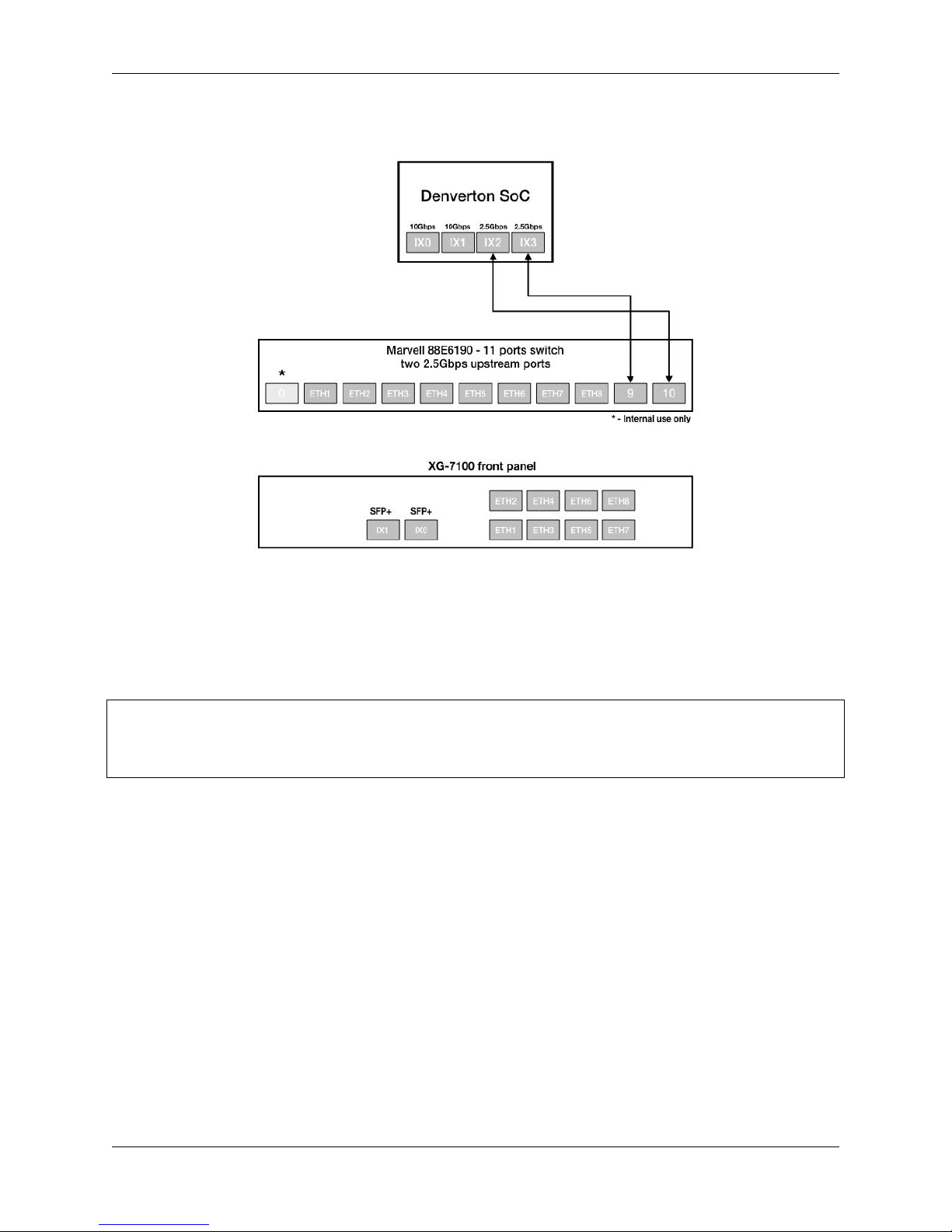
1.2 XG-7100 Switch Overview
1.2.1 Interface Links
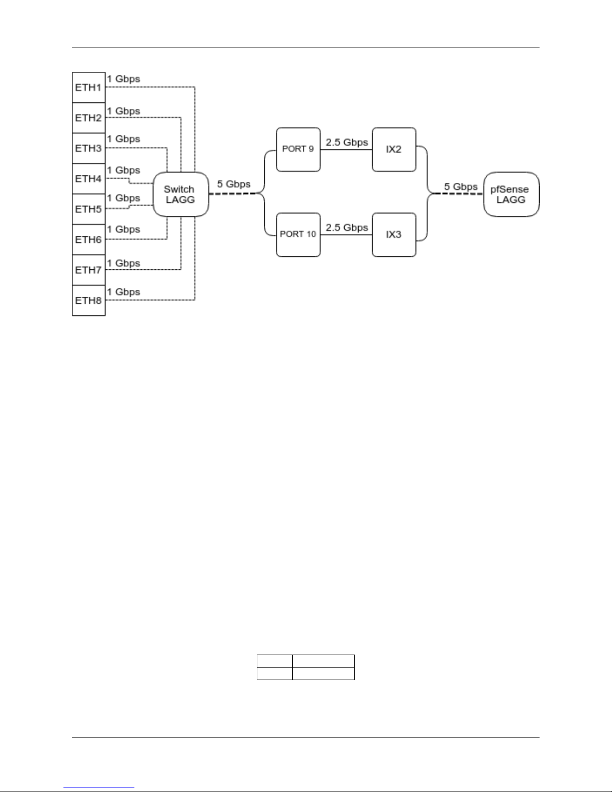
In addition to two SFP+ interfaces, there is also an ethernet switch on the XG-7100. There are eight ethernet ports on
this switch that are physically accessible - these interfaces are referred to as ETH1-ETH8. In addition to those 8 ports,
there are also three additional ports that operate behind the scenes - PORT 0, PORT 9 (ix2), and PORT 10 (ix3).
ETH1-ETH8 are gigabit switchports.
PORT 9-10 are 2.5 Gbps uplink switchports. These two ports connect the ethernet switch to a Denverton SoC. The
SFP+ interfaces (ix0 and ix1) also connect to this SoC.
The diagram below demonstrates how these interfaces are connected:
1.2. XG-7100 Switch Overview 4
Product ManualXG-7100-1U
From the operating systems perspective, there are four physical interfaces present:
ix0 - 10Gbps SFP+
ix1 - 10Gbps SFP+
ix2 - 2.5 Gbps (2500-Base-KX, switch link to SoC/CPU)
ix3 - 2.5 Gbps (2500-Base-KX, switch link to SoC/CPU)
1.2.2 Switch LAGG
ix2 and ix3 (switch uplink ports 9 and 10), are configured as a load-balanced LAGG. This provides an aggregate uplink
capable of 5Gbps for ethernet switchports ETH1-8. This is further demonstrated in the diagram below:
1.2. XG-7100 Switch Overview 5
Product ManualXG-7100-1U
When data is received on ETH1-8, the switch is capable of utilizing LAGG to determine whether that data should be
sent out of PORT 9 or PORT 10. That data then passes over one of two 2.5Gbps switch links (PORT 9/10) to the SoC.
Data coming from PORT 9 has a direct line to ix2 and data from PORT 10 has a direct line to ix3.
pfSense LAGG will then take in traffic from both ix2 and ix3 as though it came in on a single interface, lagg0. The
same concept applies to traffic sourcing from the pfSense LAGG to the switch LAGG.
1.2.3 Switch VLANs
By default, ETH1 on the the switch is configured as a WAN interface and ETH2-8 are configured as the LAN interface.
These eight switchports are customizable and each can be configured to act as an independent interface. For example,
all of these configurations are possible:
• ETH1-8 dedicated as a LAN switch
• ETH1-4 configured as a switch for LAN network A and ETH5-8 configured as a switch for LAN network B
• ETH1-8 configured as individual network interfaces
• ETH1 configured for WAN A, ETH2 configured for WAN B, ETH3 configured for LAN network A, ETH4-6
configured as a switch for LAN network B, and ETH8 configured as a H/A sync port.
These scenarios are possible by utilizing VLANs. Each of the switchports (ETH1-8 and PORT9-10) are VLAN aware
interfaces. They are capable of functioning like a standard access or trunk port:
Access Port: Adds a VLAN tag to inbound untagged traffic
Trunk Port: Allows tagged traffic containing specified VLAN IDs
In the default configuration, two VLANs are used to create the ETH1 WAN interface and ETH2-8 LAN interface:
ETH1-8 are configured to act as Access ports.
1.2. XG-7100 Switch Overview 6
WAN VLAN 4090
LAN VLAN 4091
Product ManualXG-7100-1U
• When data comes into the ETH1 interface, a VLAN tag of 4090 is added to the ethernet frame.
• When data comes into interfaces ETH2-8, a VLAN tag of 4091 is added to the ethernet frame.
PORT9-10 are configured to act as Trunk ports.
• By default, only ethernet frames containing a VLAN tag of 4090 or 4091 are allowed over the trunk.
Each VLAN configured on the switch uses the LAGG interface as its parent interface. For example, the default
interface assignment for WAN and LAN:
WAN lagg0.4090
LAN lagg0.4091
This means vlan4090 and vlan4091, as well as any other VLANs created for the switch, all share the same 5Gbps
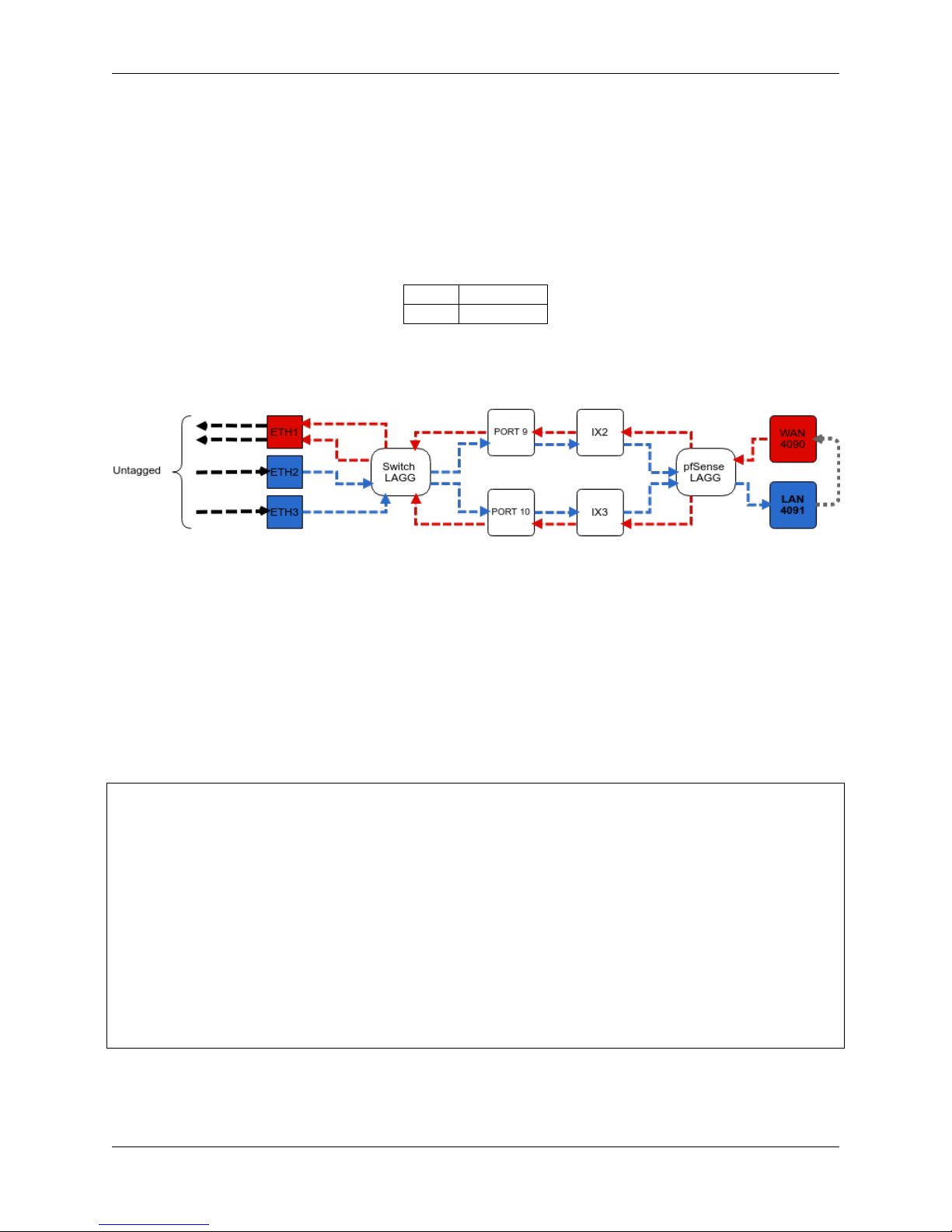
LAGG uplink across two 2.5Gbps links. The visual below demonstrates how the VLAN tagging works along with the
traffic flow:
Note that traffic leaving and entering the ETH1-3 interfaces in the visual above are untagged. Devices sending/receiving traffic over these ports do not need to be VLAN aware. The VLAN tagging that occurs within the
switch is completely transparent to clients. It’s used solely for segmenting switch traffic internally.
Aside from being able to specify whether a switchport should act as an access or trunk port, it’s also possible to disable
802.1q VLAN mode. When this is done, a third mode called Port VLAN Mode is enabled. In this mode, any and all
VLAN tags are allowed on all ports. No VLAN tags are added or removed. Think of it as a dummy switch that retains
VLAN tags on frames, if present. This mode is useful when you have numerous VLANs on your network and want to
physically segment the switch, while allowing the same VLANs on all segments of the switch.
In Port VLAN Mode, rather than specifying which interfaces are associated to a VLAN, you can specify which
physical ports form a switch. For example, if I want to create two physical switches that act as individual dummy
switches - allowing tagged or untagged traffic, I could configure Port VLAN Mode like so:
// UPLINKS
VLAN group 9, Port 9, Members 1,2,3,4,10
VLAN group 10, Port 10, Members 1,2,3,4,9
// SWITCH-A
VLAN group 1, Port 1, Members 2,3,4,9,10
VLAN group 2, Port 2, Members 1,3,4,9,10
VLAN group 3, Port 3, Members 1,2,4,9,10
VLAN group 4, Port 4, Members 1,2,3,9,10
// SWITCH-B
VLAN group 5, Port 5, Members 6,7,8
VLAN group 6, Port 6, Members 5,7,8
VLAN group 7, Port 7, Members 5,6,8
VLAN group 8, Port 8, Members 5,6,7
With this configuration in place, ETH1-8 now function like so:
1.2. XG-7100 Switch Overview 7

Product ManualXG-7100-1U
// SWITCH-A
PORT 1 = ETH1
PORT 2 = ETH2
PORT 3 = ETH3
PORT 4 = ETH4
PORT 9 = UPLINK 1
PORT 10 = UPLINK 2
// SWITCH-B
PORT 5 = ETH5
PORT 6 = ETH6
PORT 7 = ETH7
PORT 8 = ETH8
SWITCH-A
ETH1-4 can talk to each other and to the LAGG uplink. PORT9-10 are members of this switch. . .this is required for
this switch to have uplink to pfSense.
SWITCH-B
ETH5-8 can talk to each other but because PORT9-10 are not included as members, clients connecting to ETH5-8 can
only talk to other clients on ETH5-8. They will not be able to reach the SoC where ix2 and ix3 are defined, so they
never reach pfSense. This can be useful if you want a device other than pfSense to act as the primary uplink for those
connected clients.
Since WAN and LAN are assigned to lagg0.4090 and lagg0.4091, if Port VLAN Mode is enabled, be sure to update
the LAN and WAN interface assignment to reference the appropriate VLAN. Also remember to create the new VLANs
with lagg0 as the parent interface.
If Port VLAN Mode is being used to handle untagged traffic, the LAGG0 interface should be added, enabled, and
configured under Interface Assignments.
1.2.4 Configuring the Switch
Switch Section
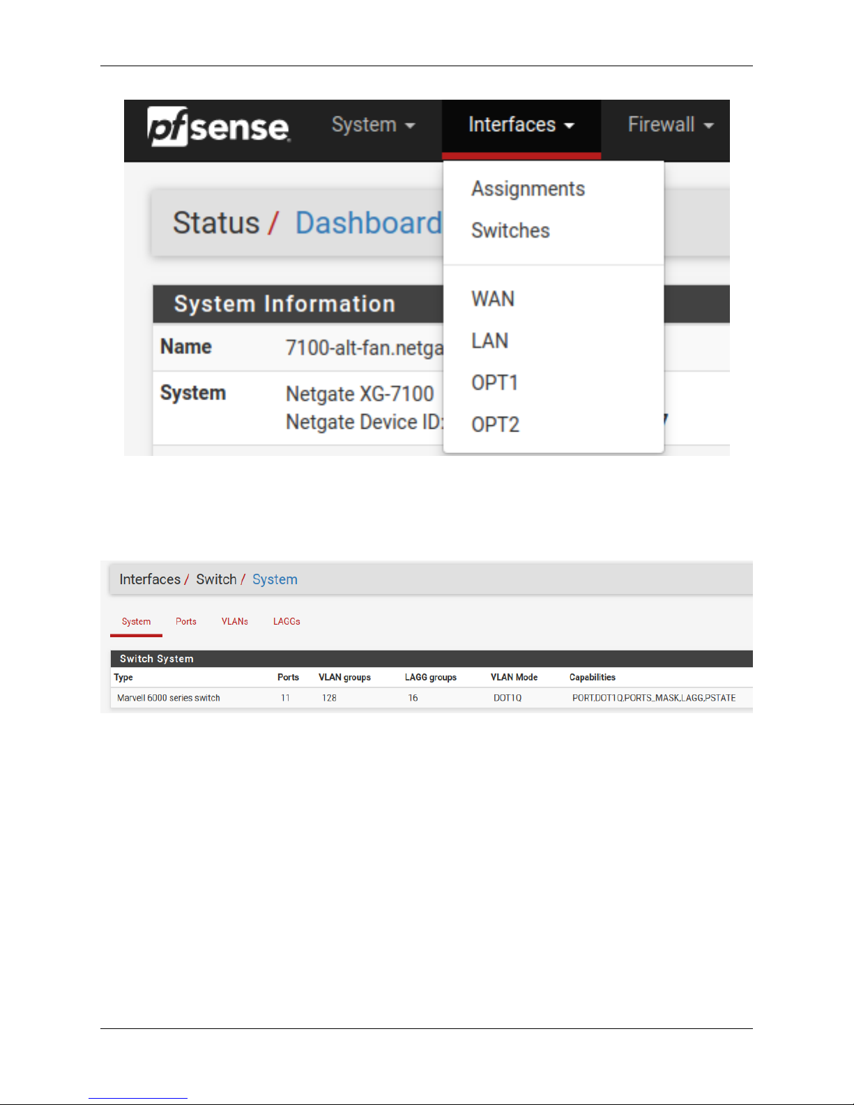
From the pfSense webGUI, there is a menu option called Switches under the Interfaces drop-down. This section
contains switch specific configuration options.
1.2. XG-7100 Switch Overview 8
Product ManualXG-7100-1U
Selecting Switches from the drop-down will bring up the Switch page with four sections:
System
Fig. 1: Information on the Marvell 6000 switch
LAGGs
Ports
Information on switchport status and port names. If 802.1q is enabled, this section can also be used to specify the
native VLAN ID for each port. The Port VID defined will be used to tag inbound untagged traffic.
VLANs
Enable/Disable 802.1q VLAN mode. Configure VLAN access/trunk interfaces with 802.1q or configure port groups
with Port VLAN Mode.
1.2. XG-7100 Switch Overview 9
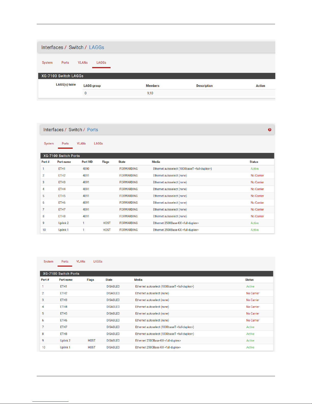
Fig. 2: Information on members of the switch LAG
Product ManualXG-7100-1U
Fig. 3: 802.1q enabled (default)
Fig. 4: Port VLAN Mode
1.2. XG-7100 Switch Overview 10
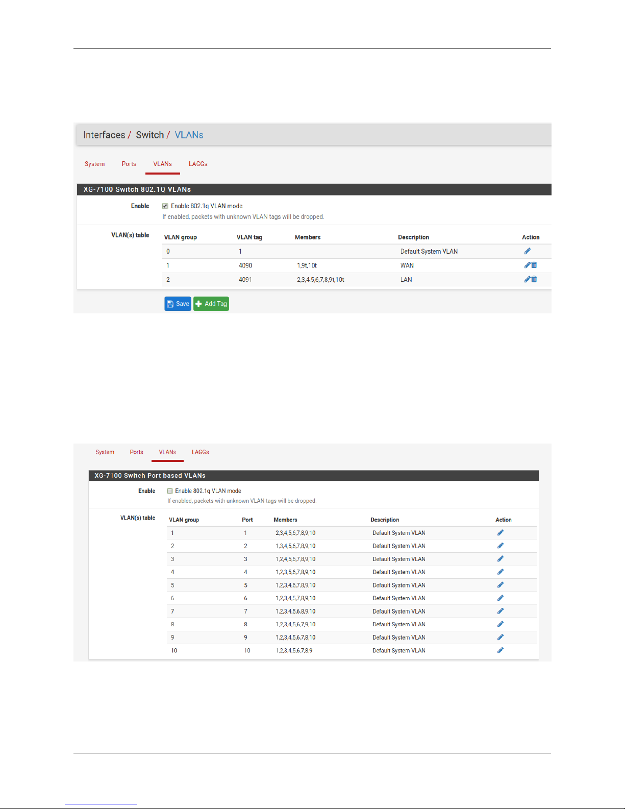
Fig. 5: 802.1q enabled (default)
Product ManualXG-7100-1U
1.2. XG-7100 Switch Overview 11
Fig. 6: Port VLAN Mode
Product ManualXG-7100-1U
Interfaces Section
There is also relevant configurations under Interfaces -> Assignments.
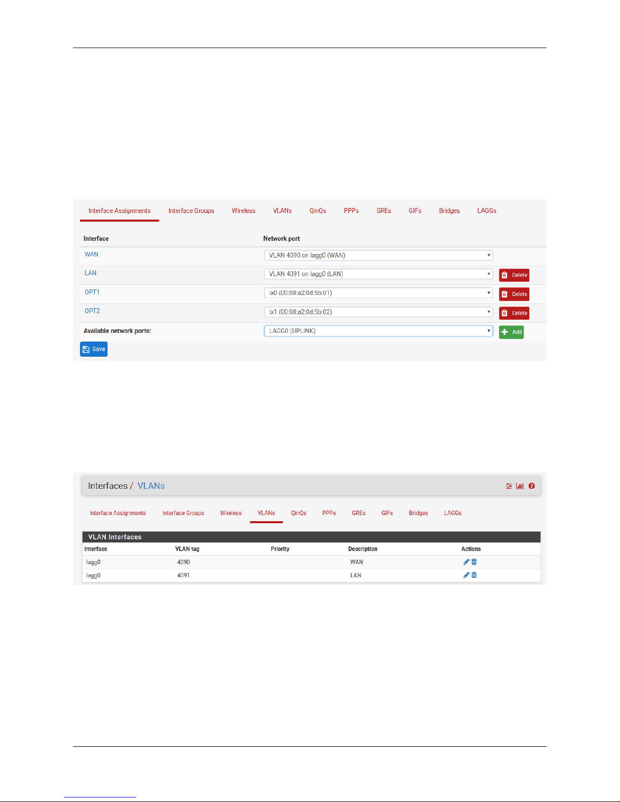
Interface Assignments
Under Interface Assignments, notice LAGG0 (UPLINK) is displayed as an available port but is not enabled in the
list of interfaces. This is because the default configuration is only expecting VLAN tagged traffic so the VLAN child
interface 4090 and 4091 are enabled instead.
VLANs
Under VLANs, the default WAN and LAN VLAN can be seen. Additional VLAN networks that will be used by the
switch should be defined here with lagg0 as the parent interface.
Any additional VLAN interface added to the switch should also be added, enabled, and configured under Interface
Assignments. Firewall rules will also be needed for new interfaces added.
LAGGs
Under LAGGs, the default lagg0 containing ix2 and ix3 can be seen. The lagg0 interface should not be modified.
1.2. XG-7100 Switch Overview 12

Product ManualXG-7100-1U
1.2.5 Switch Configuration Examples
Dedicated LAN switch
In this scenario, SFP+ port ix0 will be configured as the WAN interface. ETH1-8 will be configured as a LAN switch.
For this specific example, I’ll perform the WAN interface reassignment over console. Re-assigning the WAN can be
done from the webGUI as well.
This is what the default interface assignments look like on a XG-7100 without an addon NIC:
In this example, ix0 will be WAN, so select option 1 to re-assign WAN from lagg0.4090 to ix0:
1.2. XG-7100 Switch Overview 13
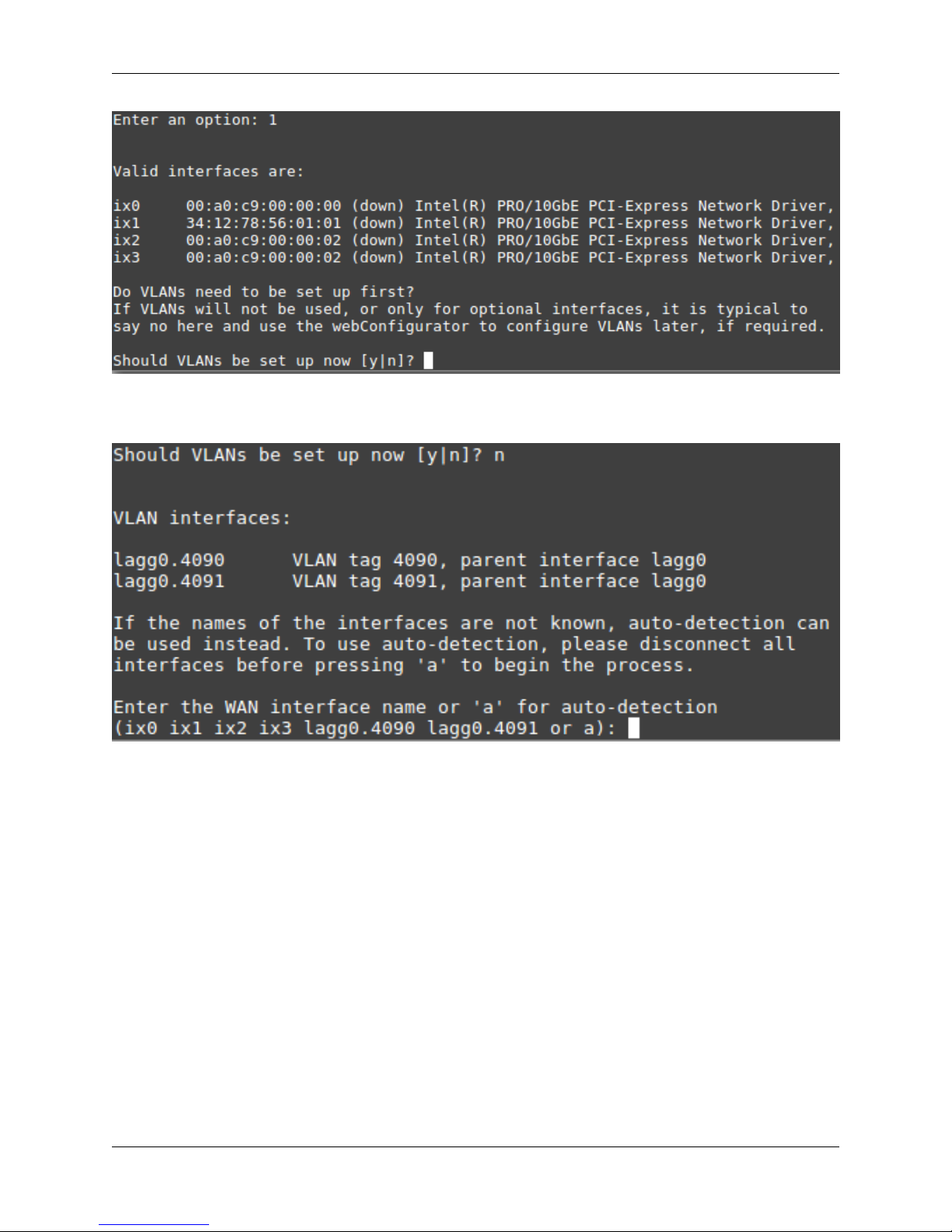
No additional VLANs are needed for this, so enter n to continue.
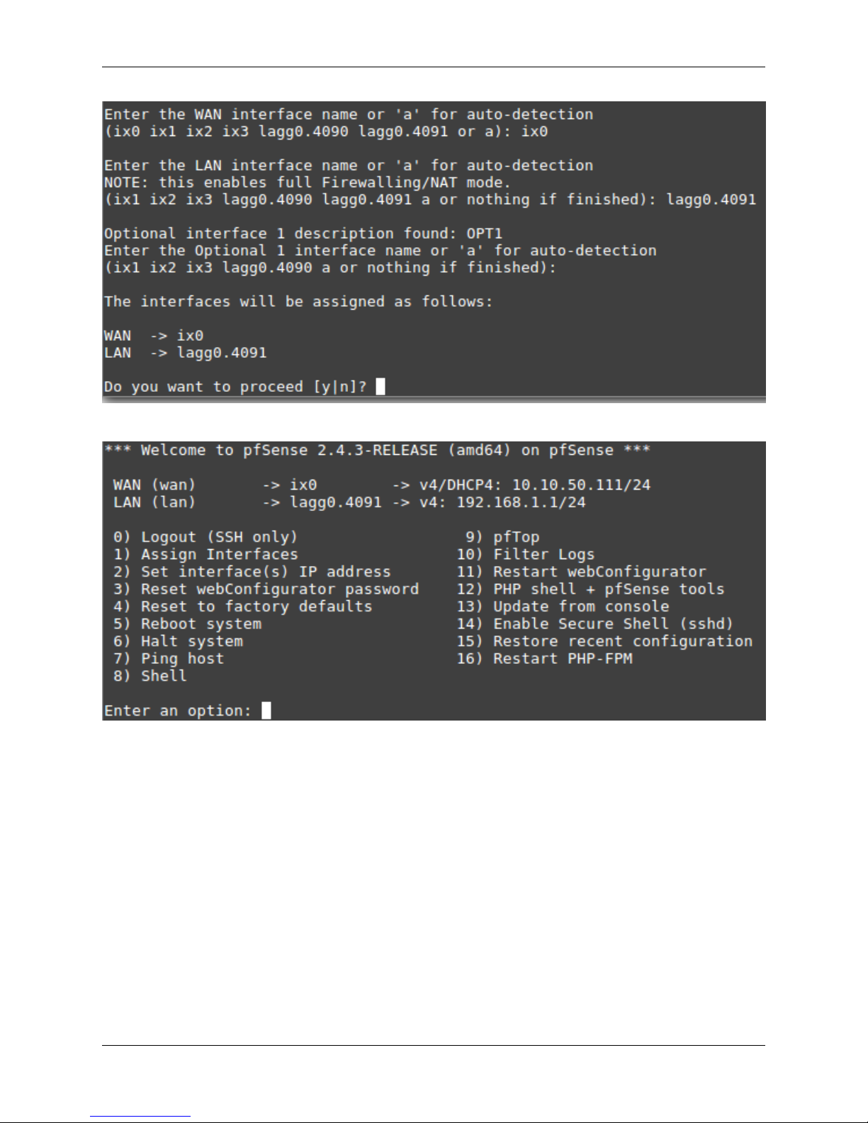
Input ix0 as the new WAN interface name:
Product ManualXG-7100-1U
Input the same default LAN interface of lagg0.4091 for the LAN interface name and press Enter to complete the
interface reassignment:
1.2. XG-7100 Switch Overview 14
The interface assignments should show like this now:
Product ManualXG-7100-1U
At this point SFP+ port ix0 is now configured as the WAN interface. The LAN interface is still configured the same as
the default. Next, the switch will need to be updated so that ETH1 (previously WAN) acts the same as ETH2-8. This
will be done from the webGUI.
From the webGUI, pull up the Switch VLAN configuration under Interfaces -> Switches -> VLANs:
1.2. XG-7100 Switch Overview 15

Product ManualXG-7100-1U
VLAN 4090 is no longer needed since WAN is dedicated to ix0 now. You can either select on the row containing
4090 to delete this entry, or click to remove port 1 as a member:
For this example, I simply removed VLAN 4090 from the switch with . Now edit the VLAN 4091 entry to include
Member 1 as shown below:
1.2. XG-7100 Switch Overview 16
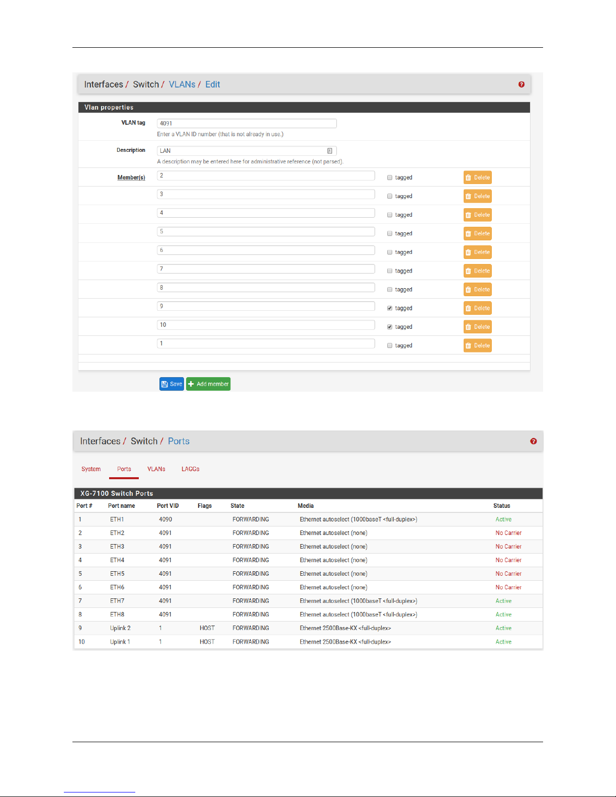
Product ManualXG-7100-1U
Next, update the PVID for ETH1 so that it uses VLAN 4091 rather than the old VLAN 4090. To do this, click on the
Ports tab and click on the 4090 Port VID to modify it:
Then click on Save:
1.2. XG-7100 Switch Overview 17
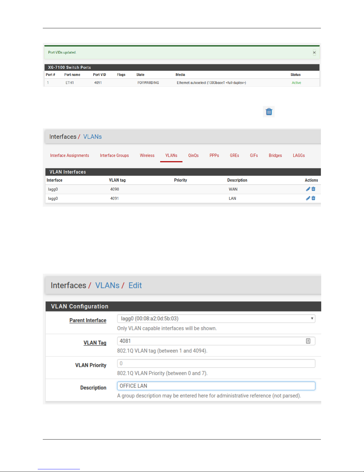
Product ManualXG-7100-1U
At this point, everything should be configured properly. ETH1-8 will act as a single LAN switch. One final step that
should be performed is to remove the old VLAN 4090 from pfSense. So far VLAN 4090 was only removed from
the switch. To remove the old VLAN, go to Interfaces -> Assignments -> VLANs and use on the 4090 row to
remove this VLAN interface:
Two LAN switches
In this scenario, the LAN switch from the previous example will be split into two LAN switches.
A new LAN network should be created in pfSense first. Similar to the existing LAN interface, another VLAN interface
should be used so the switch can segment traffic appropriately.
Create a new VLAN with lagg0 as the parent under Interfaces -> Assignments -> VLANs:
Once the VLAN has been created, it should look something like this:
1.2. XG-7100 Switch Overview 18
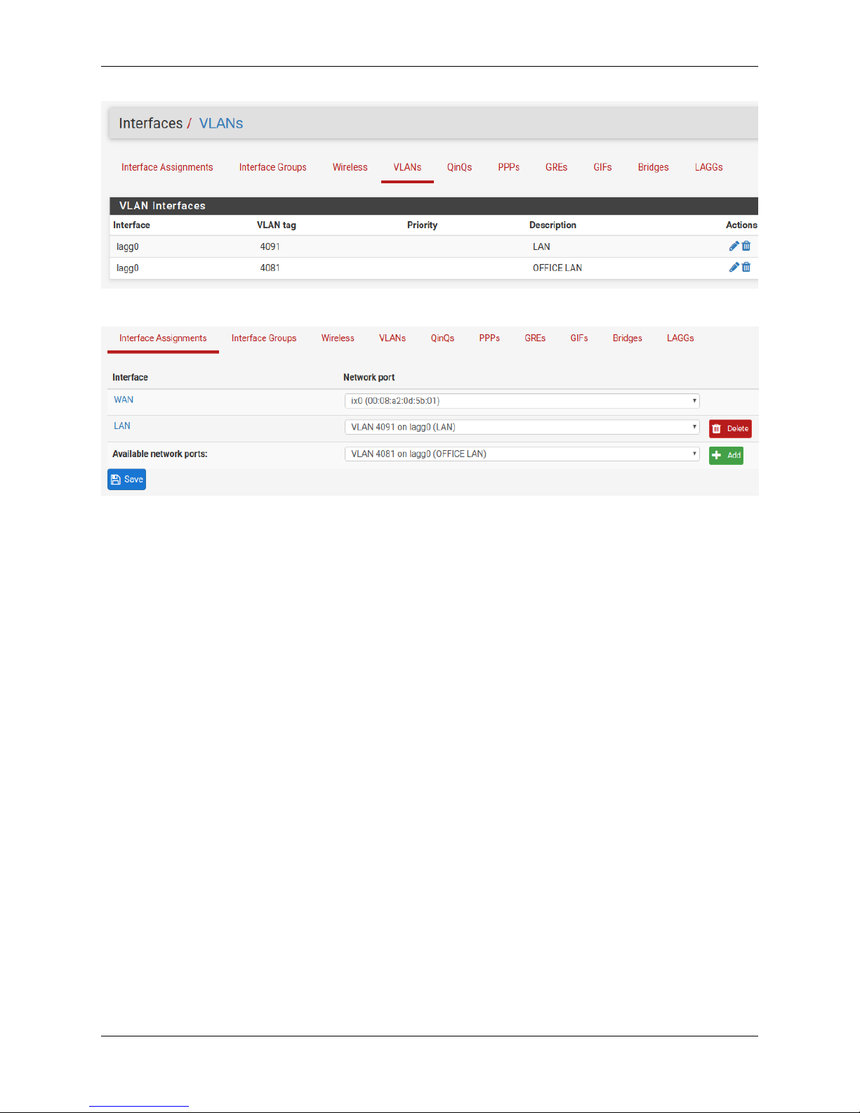
Add, enable, and configure the VLAN interface under Interfaces Assignments:
Product ManualXG-7100-1U
1.2. XG-7100 Switch Overview 19
 Loading...