

Page 1

Security Gateway Manual
SG-5100
© Copyright 2002 - 2019 Rubicon Communications LLC
Dec 06, 2019
Page 2

OUT OF THE BOX
1 Getting Started 2
2 Initial Configuration 4
3 pfSense Overview 9
4 Input and Output Ports 13
5 Safety and Legal 16
6 Connecting to the Console Port 25
7 Reinstalling pfSense Software 31
8 M.2 SATA Installation 33
9 Additional Resources 45
10 Warranty and Support 46
i
Page 3
Security Gateway Manual SG-5100
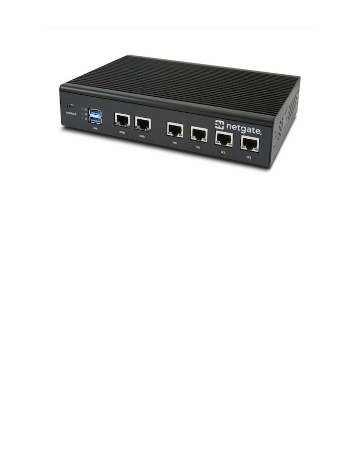
This Quick Start Guide covers the first time connection procedures for the Netgate® SG-5100 Firewall Appliance and
will provide the information needed to keep the appliance up and running.
© Copyright 2002 - 2019 Rubicon Communications LLC 1
Page 4
CHAPTER
ONE
GETTING STARTED
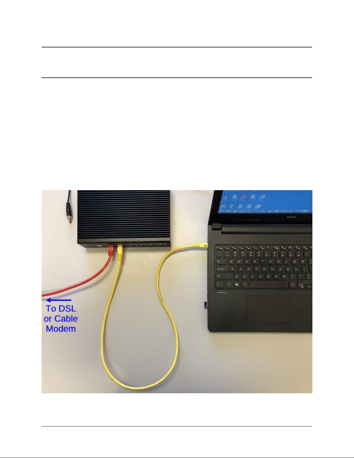
The basic firewall configuration begins with connecting the pfSense® appliance to the Internet. The pfSense appliance
should be unplugged at this time.
Connect one end of an Ethernet cable to the WAN port (shown in the Input and Output Ports section) of the pfSense
appliance. The other end of the same cable should be inserted into a port of the Cable or DSL modem. The modem
provided by the ISP should have multiple LAN ports. Any port should work.
Next, connect one end of a second Ethernet cable to the LAN port (shown in the Input and Output Ports section) of
the pfSense appliance. Connect the other end to the computer.
2
Page 5

Security Gateway Manual SG-5100
Warning: The default IP Address on the LAN subnet on the pfSense firewall is 192.168.1.1/24. The same
subnet cannot be used on both WAN and LAN, so if the default IP address on the ISP-supplied modem is also
192.168.1.1/24, disconnect the WAN interface until the LAN interface on the firewall has been renumbered
to a different subnet (like 192.168.2.1/24).
© Copyright 2002 - 2019 Rubicon Communications LLC 3
Page 6
CHAPTER
TWO
INITIAL CONFIGURATION
Plug the power cable into the power port (shown in the Input and Output Ports section) to turn on the pfSense Firewall.
Allow 4 or 5 minutes to boot up completely.
1. From the computer, log into the Web Interface
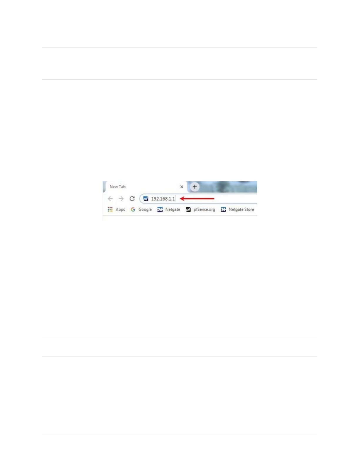
Open a web browser (Google Chrome in this example) and type in 192.186.1.1 on the address bar. Press
Enter.
Fig. 1: Enter the Default LAN IP Address
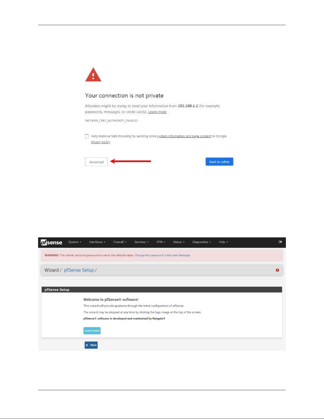
2. A warning message may appear. If this message or similar message is encountered, it is safe to proceed. Click
the Advanced Button and the click Proceed to 192.168.1.1 (unsafe) to continue.
3. At the Sign In page, enter the default pfSense username and password and click Next.
• Default Username: admin
• Default Password: pfsense
2.1 The Setup Wizard
The following steps will step through the Setup Wizard for the initial configuration of the firewall.
Note: Ignore the warning to reset the ‘admin’ account password. One of the steps in the Setup Wizard is to change
the default password.
1. Click Next to start the Setup Wizard.
2. Click Next after you have read the information on Netgate Global Support.
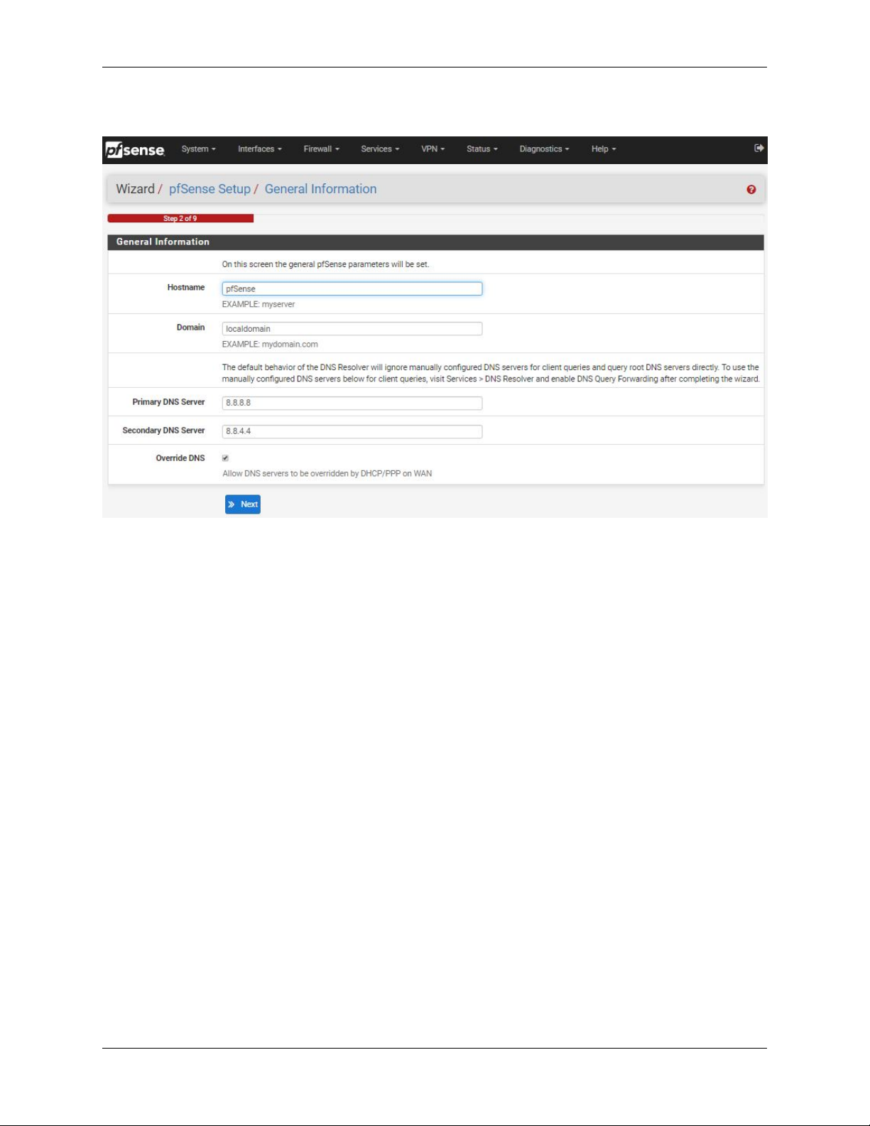
3. On the General Information page, use the following as a guide to configure the firewall.
Hostname: Any desired name can be entered. For the purposes of this guide, the default hostname pfsense
is used.
Domain: The default localdomain is used for the purposes of this tutorial.
4
Page 7
Security Gateway Manual SG-5100
Fig. 2: Click Advanced and then Proceed to 192.168.1.1 (unsafe)
Fig. 3: Click Next
© Copyright 2002 - 2019 Rubicon Communications LLC 5
Page 8
Security Gateway Manual SG-5100
DNS Servers: For purposes of this setup guide, use the Google public DNS servers (8.8.8.8 and 8.8.4.4).
Fig. 4: Type in the DNS Server information and Click Next
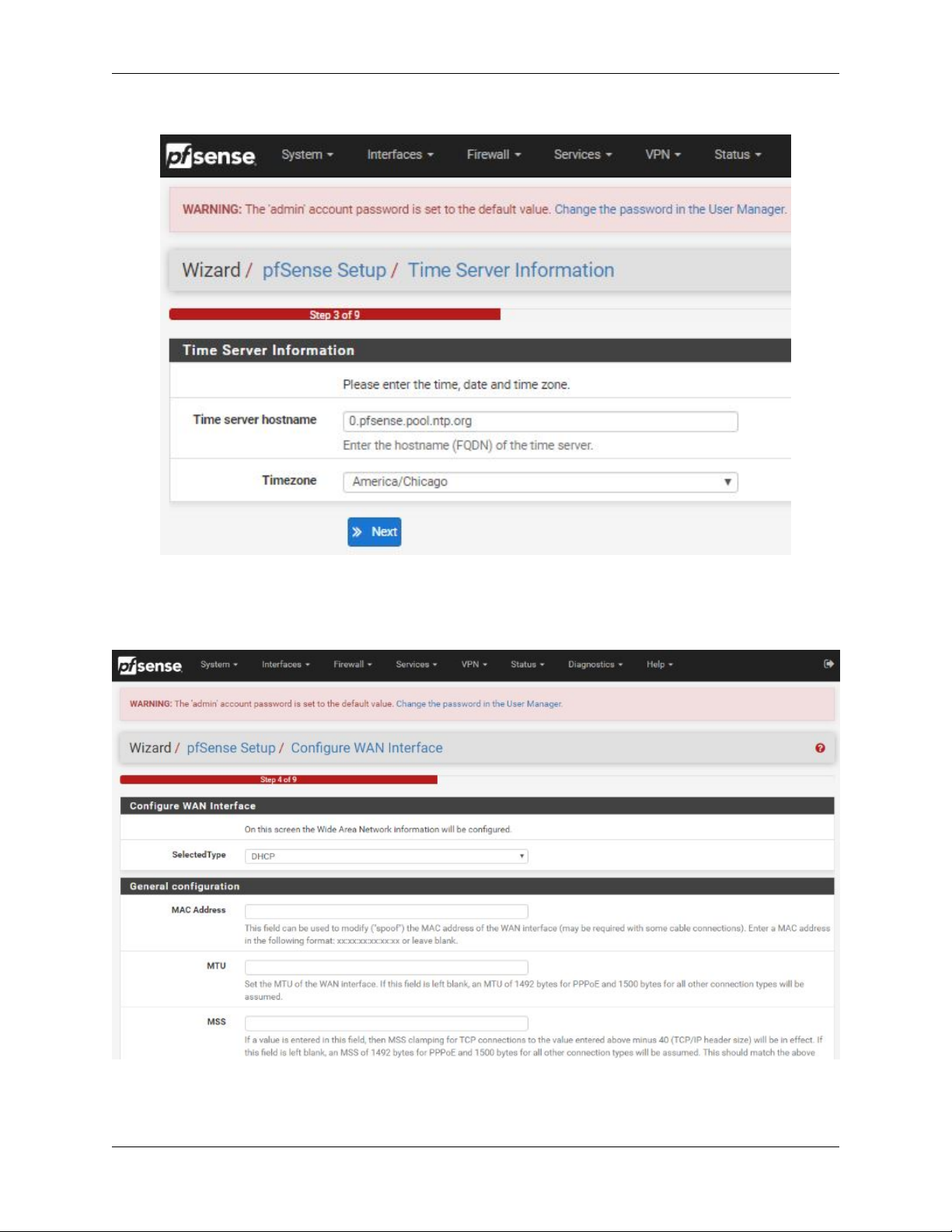
4. Use the following information for the Time Server Information page.
Time Server Hostname: Use the default pfSense time server address.
Timezone: Select the time zone for the location of the firewall. For this guide, the Timezone will be set to
America/Chicago for US Central time.
5. The WAN interface is the Public IP address the network will use to communicate with the Internet. Use the
following information for the WAN configuration page.
DHCP is the default and is the most common type of interface for home cable modems.
Default settings for the other items on this page should be acceptable for normal home users.
6. Configuring LAN IP Address & Subnet Mask. The default LAN IP address of 192.168.1.1 and subnet mask
of 24 is usually sufficient.
7. Change the Admin Password. Enter the same password in both fields.
8. Click Reload to save the configuration.
9. After a few seconds, a message will indicate the Setup Wizard has completed. To proceed to the pfSense
dashboard, click Finish.
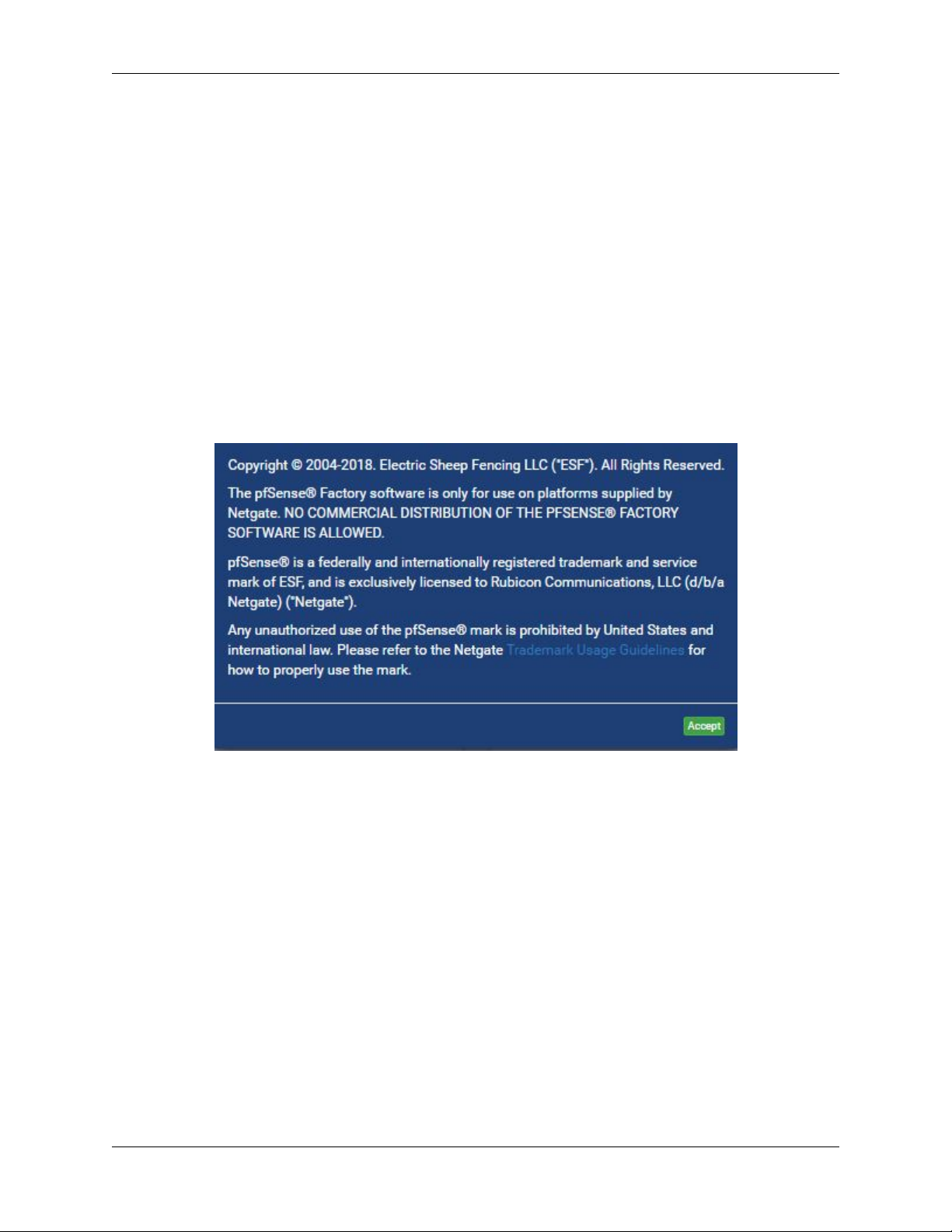
10. A final notification screen will appear stating that NO COMMERCIAL DISTRIBUTION. .. Click Accept
to continue to the pfSense dashboard.
This completes the basic configuration for the pfSense firewall.
© Copyright 2002 - 2019 Rubicon Communications LLC 6
Page 9
Security Gateway Manual SG-5100
Fig. 5: Change the Timezone and Click Next
Fig. 6: Default Settings Should be Acceptable. Click Next
© Copyright 2002 - 2019 Rubicon Communications LLC 7
Page 10
Security Gateway Manual SG-5100
Fig. 7: Read and Click Accept
© Copyright 2002 - 2019 Rubicon Communications LLC 8
Page 11
CHAPTER
THREE
PFSENSE OVERVIEW
This page provides an overview of the pfSense® dashboard and navigation. It also provides information on how to
perform frequent tasks such as backing up the pfSense software and connecting to the pfSense firewall console.
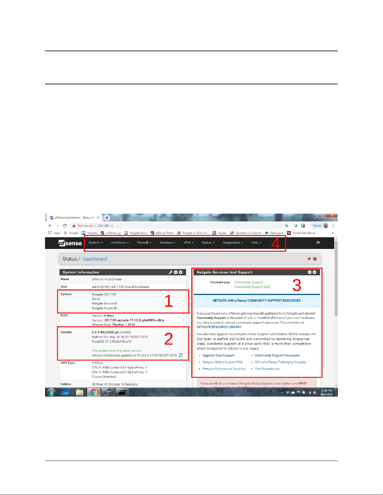
3.1 The Dashboard
pfSense software is highly configurable, all of which can be done through the dashboard. This orientation will help to
navigate and further configure the firewall.
Fig. 1: The pfSense Dashboard
Section 1 shows important system information such as the model, Serial Number, and Netgate Device ID for this
pfsense firewall.
Section 2 identifies what version of pfSense software is installed, and if an update is available.
9
Page 12
Security Gateway Manual SG-5100
Section 3 describes Netgate Service and Support.
Section 4 shows the various menu headings. Each menu heading has drop-down options for a wide range of configu-
ration choices.
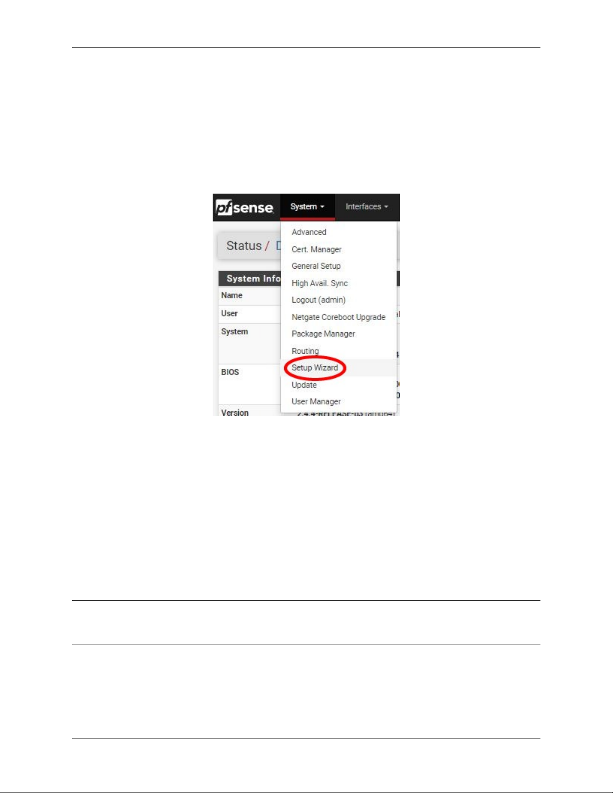
3.2 Re-running the Setup Wizard
To re-run the Setup Wizard, navigate to System -> Setup Wizard.
Fig. 2: Re-run the Setup Wizard
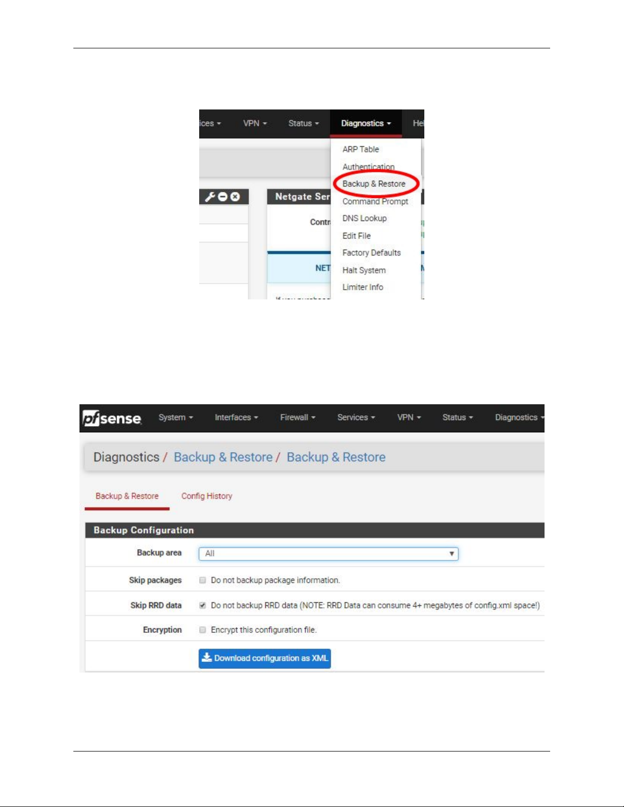
3.3 Backup and Restore
It is important to backup the firewall configuration prior to updating or making any configuration changes. From the
menu at the top of the page, browse to Diagnostics > Backup/Restore.
Click Download configuration as XML and save a copy of the firewall configuration to the computer connected to the pfSense firewall.
This backup (or any backup) can be restored from the same screen by choosing the backed up file under Restore
Configuration.
Note: Auto Config Backup is a built-in service located at Services -> Auto Config Backup. This service will save
up to 100 encrypted backup files automatically, any time a change to the configuration has been made. Visit the Auto
Config Backup page for more information.
3.3.1 Connecting to the Console
There are times when accessing the console is required. Perhaps GUI console access has been locked out, or the
password has been lost or forgotten.
© Copyright 2002 - 2019 Rubicon Communications LLC 10
Page 13
Security Gateway Manual SG-5100
Fig. 3: Backup & Restore
Fig. 4: Click Download configuration as XML
© Copyright 2002 - 2019 Rubicon Communications LLC 11
Page 14

Security Gateway Manual SG-5100
See also:
Connecting to the Console Port Connect to the console. Cable is required.
Tip: To learn more about getting the most out of your pfSense appliance, sign up for a pfSense Training course or
browse our extensive Resource Library.
© Copyright 2002 - 2019 Rubicon Communications LLC 12
Page 15
4.1 Rear Side
CHAPTER
FOUR
INPUT AND OUTPUT PORTS
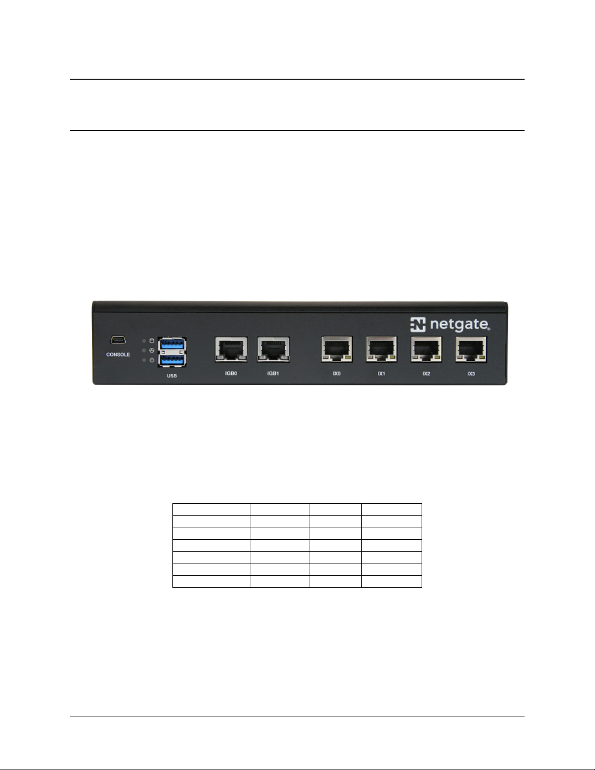
4.2 Ethernet Ports
Interface Name Port Name Port Type Port Speed
WAN IGB0 RJ-45 1 Gbps
LAN IGB1 RJ-45 1 Gbps
OPT1 IX0 RJ-45 1 Gbps
OPT2 IX1 RJ-45 1 Gbps
OPT3 IX2 RJ-45 1 Gbps
OPT4 IX3 RJ-45 1 Gbps
13
Page 16

Security Gateway Manual SG-5100
Status LED State Description
Left LED
(Link Status)
Right LED
(Speed)
Note: All Ethernet ports of the pfSense® appliance support auto-MDIX and are capable of utilizing either straightthrough or crossover ethernet cables.
Warning: The ix(4) driver used for ports IX0-IX3 does not support ALTQ traffic shaping directly. Limiters
may be used instead, or use tagged VLAN interfaces which can be used with ALTQ traffic shaping.
Solid Amber Link has been established and there
is no activity on this port
Blinking Amber Link has been established and there
is activity on this port
Off No link has been established
Solid Green Operating asa 100 Mbpsconnection
Blinking Amber Operating as a Gigabit connection
(1000 Mbps)
Off No link has been established
4.3 Other Ports and Indicators
• Console (Mini-USB)
• Status LEDs
• 2x USB 3.0
Status LED Description
Top LED Add-on storage activity (does not show eMMC activity)
Middle LED Activity
Bottom LED Power
4.4 Front Side
1. Receessed Reset Button
© Copyright 2002 - 2019 Rubicon Communications LLC 14
Page 17

Security Gateway Manual SG-5100
2. Power Button
3. Power (12VDC with threaded locking connector)
Center Pin Positive
© Copyright 2002 - 2019 Rubicon Communications LLC 15
Page 18

• Safety Notices
• Electrical Safety Information
• FCC Compliance
• Industry Canada
• CE Marking
• RoHS/WEEE Compliance Statement
– English
– Deutsch
CHAPTER
FIVE
SAFETY AND LEGAL
– Español
– Français
– Italiano
• Declaration of Conformity
–ˇCesky[Czech]
– Dansk [Danish]
– Nederlands [Dutch]
– English
– Eesti [Estonian]
– Suomi [Finnish]
– Deutsch [German]
– ΕλληνικH [Greek]
– Magyar [Hungarian]
– Íslenska [Icelandic]
– Italiano [Italian]
– Latviski [Latvian]
– Lietuviškai [Lithuanian]
– Malti [Maltese]
16
Page 19

Security Gateway Manual SG-5100
– Norsk [Norwegian]
– Slovensky [Slovak]
– Svenska [Swedish]
– Español [Spanish]
– Polski [Polish]
– Português [Portuguese]
– Român˘a [Romanian]
• Disputes
• Applicable Law
• Site Policies, Modification, and Severability
• Miscellaneous
• Limited Warranty
5.1 Safety Notices
1. Read, follow, and keep these instructions.
2. Heed all warnings.
3. Only use attachments/accessories specified by the manufacturer
Warning: Do not use this product in location that can be submerged by water.
Warning: Do not use this product during an electrical storm to avoid electrical shock.
5.2 Electrical Safety Information
1. Compliance is required with respect to voltage, frequency, and current requirements indicated on the manufacturer’s label. Connection to a different power source than those specified may result in improper operation,
damage to the equipment or pose a fire hazard if the limitations are not followed.
2. There are no operator serviceable parts inside this equipment. Service should be provided only by a qualified
service technician.
3. This equipment is provided with a detachable power cord which has an integral safety ground wire intended for
connection to a grounded safety outlet.
a) Do not substitute the power cord with one that is not the provided approved type. If a 3 prong plug is
provided, never use an adapter plug to connect to a 2-wire outlet as this will defeat the continuity of the
grounding wire.
b) The equipment requires the use of the ground wire as a part of the safety certification, modification or
misuse can provide a shock hazard that can result in serious injury or death.
© Copyright 2002 - 2019 Rubicon Communications LLC 17
Page 20

Security Gateway Manual SG-5100
c) Contact a qualified electrician or the manufacturer if there are questions about the installation prior to
connecting the equipment.
d) Protective grounding/earthing is provided by Listed AC adapter. Building installation shall provide appro-
priate short-circuit backup protection.
e) Protective bonding must be installed in accordance with local national wiring rules and regulations.
5.3 FCC Compliance
Changes or modifications not expressly approved by the party responsible for compliance could void the user’s authority to operate the equipment. This device complies with Part 15 of the FCC Rules. Operation is subject to the
following two conditions:
1. This device may not cause harmful interference, and
2. This device must accept any interference received, including interference that may cause undesired operation.
Note: This equipment has been tested and found to comply with the limits for a Class B digital device, pursuant
to part 15 of the FCC Rules. These limits are designed to provide reasonable protection against harmful interference
when the equipment is operated in a residential environment.
5.4 Industry Canada
This Class B digital apparatus complies with Canadian ICES-3(B). Cet appareil numérique de la classe B est conforme
à la norme NMB-3(B) Canada.
5.5 CE Marking
CE marking on this product represents the product is in compliance with all directives that are applicable to it.
5.6 RoHS/WEEE Compliance Statement
5.6.1 English
European Directive 2002/96/EC requires that the equipment bearing this symbol on the product and/or its packaging
must not be disposed of with unsorted municipal waste. The symbol indicates that this product should be disposed
of separately from regular household waste streams. It is your responsibility to dispose of this and other electric and
electronic equipment via designated collection facilities appointed by the government or local authorities. Correct
disposal and recycling will help prevent potential negative consequences to the environment and human health. For
more detailed information about the disposal of your old equipment, please contact your local authorities, waste
disposal service, or the shop where you purchased the product.
© Copyright 2002 - 2019 Rubicon Communications LLC 18
Page 21

Security Gateway Manual SG-5100
5.6.2 Deutsch
Die Europäische Richtlinie 2002/96/EC verlangt, dass technische Ausrüstung, die direkt am Gerät und/oder an der
Verpackung mit diesem Symbol versehen ist, nicht zusammen mit unsortiertem Gemeindeabfall entsorgt werden darf.
Das Symbol weist darauf hin, dass das Produkt von regulärem Haushaltmüll getrennt entsorgt werden sollte. Es liegt in
Ihrer Verantwortung, dieses Gerät und andere elektrische und elektronische Geräte über die dafür zuständigen und von
der Regierung oder örtlichen Behörden dazu bestimmten Sammelstellen zu entsorgen. Ordnungsgemäßes Entsorgen
und Recyceln trägt dazu bei, potentielle negative Folgen für Umwelt und die menschliche Gesundheit zu vermeiden.
Wenn Sie weitere Informationen zur Entsorgung Ihrer Altgeräte benötigen, wenden Sie sich bitte an die örtlichen
Behörden oder städtischen Entsorgungsdienste oder an den Händler, bei dem Sie das Produkt erworben haben.
5.6.3 Español
La Directiva 2002/96/CE de la UE exige que los equipos que lleven este símbolo en el propio aparato y/o en su
embalaje no deben eliminarse junto con otros residuos urbanos no seleccionados. El símbolo indica que el producto
en cuestión debe separarse de los residuos domésticos convencionales con vistas a su eliminación. Es responsabilidad
suya desechar este y cualesquiera otros aparatos eléctricos y electrónicos a través de los puntos de recogida que ponen
a su disposición el gobierno y las autoridades locales. Al desechar y reciclar correctamente estos aparatos estará
contribuyendo a evitar posibles consecuencias negativas para el medio ambiente y la salud de las personas. Si desea
obtener información más detallada sobre la eliminación segura de su aparato usado, consulte a las autoridades locales,
al servicio de recogida y eliminación de residuos de su zona o pregunte en la tienda donde adquirió el producto.
5.6.4 Français
La directive européenne 2002/96/CE exige que l’équipement sur lequel est apposé ce symbole sur le produit et/ou son
emballage ne soit pas jeté avec les autres ordures ménagères. Ce symbole indique que le produit doit être éliminé dans
un circuit distinct de celui pour les déchets des ménages. Il est de votre responsabilité de jeter ce matériel ainsi que
tout autre matériel électrique ou électronique par les moyens de collecte indiqués par le gouvernement et les pouvoirs
publics des collectivités territoriales. L’élimination et le recyclage en bonne et due forme ont pour but de lutter contre
l’impact néfaste potentiel de ce type de produits sur l’environnement et la santé publique. Pour plus d’informations
sur le mode d’élimination de votre ancien équipement, veuillez prendre contact avec les pouvoirs publics locaux, le
service de traitement des déchets, ou l’endroit où vous avez acheté le produit.
5.6.5 Italiano
La direttiva europea 2002/96/EC richiede che le apparecchiature contrassegnate con questo simbolo sul prodotto e/o
sull’imballaggio non siano smaltite insieme ai rifiuti urbani non differenziati. Il simbolo indica che questo prodotto
non deve essere smaltito insieme ai normali rifiuti domestici. È responsabilità del proprietario smaltire sia questi
prodotti sia le altre apparecchiature elettriche ed elettroniche mediante le specifiche strutture di raccolta indicate dal
governo o dagli enti pubblici locali. Il corretto smaltimento ed il riciclaggio aiuteranno a prevenire conseguenze
potenzialmente negative per l’ambiente e per la salute dell’essere umano. Per ricevere informazioni più dettagliate
circa lo smaltimento delle vecchie apparecchiature in Vostro possesso, Vi invitiamo a contattare gli enti pubblici di
competenza, il servizio di smaltimento rifiuti o il negozio nel quale avete acquistato il prodotto.
© Copyright 2002 - 2019 Rubicon Communications LLC 19
Page 22

Security Gateway Manual SG-5100
5.7 Declaration of Conformity
5.7.1ˇCesky[Czech]
NETGATE tímto prohla uje, e tento NETGATE device, je ve shod se základními po adavky a dal ími p íslu n mi
ustanoveními sm rnice 1999/5/ES.
5.7.2 Dansk [Danish]
Undertegnede NETGATE erklærer herved, at følgende udstyr NETGATE device, overholder de væsentlige krav og
øvrige relevante krav i direktiv 1999/5/EF.
5.7.3 Nederlands [Dutch]
Hierbij verklaart NETGATE dat het toestel NETGATE device, in overeenstemming is met de essentiële eisen en
de andere relevante bepalingen van richtlijn 1999/5/EG. Bij deze verklaart NETGATE dat deze NETGATE device,
voldoet aan de essentiële eisen en aan de overige relevante bepalingen van Richtlijn 1999/5/EC.
5.7.4 English
Hereby, NETGATE , declares that this NETGATE device, is in compliance with the essential requirements and other
relevant provisions of Directive 1999/5/EC.
5.7.5 Eesti [Estonian]
Käesolevaga kinnitab NETGATE seadmeNETGATEdevice, vastavust direktiivi 1999/5/EÜ põhinõuetele ja nimetatud
direktiivist tulenevatele teistele asjakohastele sätetele.
5.7.6 Suomi [Finnish]
NETGATE vakuuttaa täten että NETGATE device, tyyppinen laite on direktiivin 1999/5/EY oleellisten vaatimusten
ja sitä koskevien direktiivin muiden ehtojen mukainen. Français [French] Par la présente NETGATE déclare que
l’appareil Netgate, device est conforme aux exigences essentielles et aux autres dispositions pertinentes de la directive
1999/5/CE.
5.7.7 Deutsch [German]
Hiermit erklärt Netgate, dass sich diese NETGATE device, in Übereinstimmung mit den grundlegenden Anforderungen und den anderen relevanten Vorschriften der Richtlinie 1999/5/EG befindet”. (BMWi)
5.7.8 ΕλληνικH [Greek]
ΜΕ ΤΗΝ ΠΑΡΟΥΣΑ NETGATE ΔΗΛΩΝΕΙ ΟΤΙ NETGATE device, ΣΥΜΜΟΡΦΩΝΕΤΑΙ ΠΡΟΣ ΤΙΣ ΟΥΣΙ-
ΩΔΕΙΣ ΑΠΑΙΤΗΣΕΙΣ ΚΑΙ ΤΙΣ ΛΟΙΠΕΣ ΣΧΕΤΙΚΕΣ ΔΙΑΤΑΞΕΙΣ ΤΗΣ ΟΔΗΓΙΑΣ 1995/5/ΕΚ.
© Copyright 2002 - 2019 Rubicon Communications LLC 20
Page 23

Security Gateway Manual SG-5100
5.7.9 Magyar [Hungarian]
Alulírott, NETGATE nyilatkozom, hogy a NETGATE device, megfelel a vonatkozó alapvetõ követelményeknek és az
1999/5/EC irányelv egyéb elõírásainak.
5.7.10 Íslenska [Icelandic]
Hér me l sir NETGATE yfir ví a NETGATE device, er í samræmi vi grunnkröfur og a rar kröfur, sem ger ar eru í
tilskipun 1999/5/EC.
5.7.11 Italiano [Italian]
Con la presente NETGATE dichiara che questo NETGATE device, è conforme ai requisiti essenziali ed alle altre
disposizioni pertinenti stabilite dalla direttiva 1999/5/CE.
5.7.12 Latviski [Latvian]
Ar o NETGATE deklar , ka NETGATE device, atbilst Direkt vas 1999/5/EK b tiskaj m pras b m un citiem ar to saist
tajiem noteikumiem.
5.7.13 Lietuviškai [Lithuanian]
NETGATE deklaruoja, kad šis NETGATE ı˛renginys atitinka esminius reikalavimus ir kitas 1999/5/EB Direktyvos
nuostatas.
5.7.14 Malti [Maltese]
Hawnhekk, Netgate, jiddikjara li dan NETGATE device, jikkonforma mal- ti ijiet essenzjali u ma provvedimenti o rajn
relevanti li hemm fid-Dirrettiva 1999/5/EC.
5.7.15 Norsk [Norwegian]
NETGATE erklærer herved at utstyret NETGATE device, er i samsvar med de grunnleggende krav og øvrige relevante
krav i direktiv 1999/5/EF.
5.7.16 Slovensky [Slovak]
NETGATE t mto vyhlasuje, e NETGATE device, sp a základné po iadavky a v etky príslu né ustanovenia Smernice
1999/5/ES.
5.7.17 Svenska [Swedish]
Härmed intygar NETGATE att denna NETGATE device, står I överensstämmelse med de väsentliga egenskapskrav
och övriga relevanta bestämmelser som framgår av direktiv 1999/5/EG.
© Copyright 2002 - 2019 Rubicon Communications LLC 21
Page 24

Security Gateway Manual SG-5100
5.7.18 Español [Spanish]
Por medio de la presente NETGATE declara que el NETGATE device, cumple con los requisitos esenciales y cualesquiera otras disposiciones aplicables o exigibles de la Directiva 1999/5/CE.
5.7.19 Polski [Polish]
Niniejszym, firma NETGATE o wiadcza, e produkt serii NETGATE device, spełnia zasadnicze wymagania i inne
istotne postanowienia Dyrektywy 1999/5/EC.
5.7.20 Português [Portuguese]
NETGATE declara que este NETGATE device, está conforme com os requisitos essenciais e outras disposições da
Directiva 1999/5/CE.
5.7.21 Român˘a [Romanian]
Prin prezenta, NETGATE declar˘a c˘a acest dispozitiv NETGATE este în conformitate cu cerint,ele esent,iale s,i alte
prevederi relevante ale Directivei 1999/5/CE.
5.8 Disputes
ANY DISPUTE OR CLAIM RELATING IN ANY WAY TO YOUR USE OF ANY PRODUCTS/SERVICES, OR
TO ANY PRODUCTS OR SERVICES SOLD OR DISTRIBUTED BY RCL OR ESF WILL BE RESOLVED BY
BINDING ARBITRATION IN AUSTIN, TEXAS, RATHER THAN IN COURT. The Federal Arbitration Act and
federal arbitration law apply to this agreement.
THERE IS NO JUDGE OR JURY IN ARBITRATION, AND COURT REVIEW OF AN ARBITRATION AWARD
IS LIMITED. HOWEVER, AN ARBITRATOR CAN AWARD ON AN INDIVIDUAL BASIS THE SAME DAMAGES AND RELIEF AS A COURT (INCLUDING INJUNCTIVE AND DECLARATORY RELIEF OR STATUTORY DAMAGES), AND MUST FOLLOW THE TERMS OF THESE TERMS AND CONDITIONS OF USE AS
A COURT WOULD.
To begin an arbitration proceeding, you must send a letter requesting arbitration and describing your claim to the
following:
Rubicon Communications LLC
Attn.: Legal Dept.
4616 West Howard Lane, Suite 900
Austin, Texas 78728
legal@netgate.com
The arbitration will be conducted by the American Arbitration Association (AAA) under its rules. The AAA’s rules
are available at www.adr.org. Payment of all filing, administration and arbitrator fees will be governed by the AAA’s
rules.
We each agree that any dispute resolution proceedings will be conducted only on an individual basis and not in a class,
consolidated or representative action. We also both agree that you or we may bring suit in court to enjoin infringement
or other misuse of intellectual property rights.
© Copyright 2002 - 2019 Rubicon Communications LLC 22
Page 25

Security Gateway Manual SG-5100
5.9 Applicable Law
By using any Products/Services, you agree that the Federal Arbitration Act, applicable federal law, and the laws of
the state of Texas, without regard to principles of conflict of laws, will govern these terms and conditions of use and
any dispute of any sort that might arise between you and RCL and/or ESF. Any claim or cause of action concerning
these terms and conditions or use of the RCL and/or ESF website must be brought within one (1) year after the claim
or cause of action arises. Exclusive jurisdiction and venue for any dispute or claim arising out of or relating to the
parties’ relationship, these terms and conditions, or the RCL and/or ESF website, shall be with the arbitrator and/or
courts located in Austin, Texas. The judgment of the arbitrator may be enforced by the courts located in Austin, Texas,
or any other court having jurisdiction over you.
5.10 Site Policies, Modification, and Severability
Please review our other policies, such as our pricing policy, posted on our websites. These policies also govern your
use of Products/Services. We reserve the right to make changes to our site, policies, service terms, and these terms
and conditions of use at any time.
5.11 Miscellaneous
If any provision of these terms and conditions of use, or our terms and conditions of sale, are held to be invalid, void
or unenforceable, the invalid, void or unenforceable provision shall be modified to the minimum extent necessary in
order to render it valid or enforceable and in keeping with the intent of these terms and conditions. If such modification
is not possible, the invalid or unenforceable provision shall be severed, and the remaining terms and conditions shall
be enforced as written. Headings are for reference purposes only and in no way define, limit, construe or describe the
scope or extent of such section. Our failure to act with respect to a breach by you or others does not waive our right
to act with respect to subsequent or similar breaches. These terms and conditions set forth the entire understanding
and agreement between us with respect to the subject matter hereof, and supersede any prior oral or written agreement
pertaining thereto, except as noted above with respect to any conflict between these terms and conditions and our
reseller agreement, if the latter is applicable to you.
5.12 Limited Warranty
DISCLAIMER OF WARRANTIES AND LIMITATION OF LIABILITY
THE PRODUCTS/SERVICES AND ALL INFORMATION, CONTENT, MATERIALS, PRODUCTS (INCLUDING SOFTWARE) AND OTHER SERVICES INCLUDED ON OR OTHERWISE MADE AVAILABLE TO YOU
THROUGH THE PRODUCTS/SERVICES ARE PROVIDED BY US ON AN “AS IS” AND “AS AVAILABLE” BASIS, UNLESS OTHERWISE SPECIFIED IN WRITING. WE MAKE NO REPRESENTATIONS OR WARRANTIES
OF ANY KIND, EXPRESS OR IMPLIED, AS TO THE OPERATION OF THE PRODUCTS/SERVICES, OR THE
INFORMATION, CONTENT, MATERIALS, PRODUCTS (INCLUDING SOFTWARE) OR OTHER SERVICES
INCLUDED ON OR OTHERWISE MADE AVAILABLE TO YOU THROUGH THE PRODUCTS/SERVICES, UNLESS OTHERWISE SPECIFIED IN WRITING. YOU EXPRESSLY AGREE THAT YOUR USE OF THE PRODUCTS/SERVICES IS AT YOUR SOLE RISK.
TO THE FULL EXTENT PERMISSIBLE BY APPLICABLE LAW, RUBICON COMMUNICATIONS, LLC (RCL)
AND ELECTRIC SHEEP FENCING (ESF) DISCLAIM ALL WARRANTIES, EXPRESS OR IMPLIED, INCLUDING, BUT NOT LIMITED TO, IMPLIED WARRANTIES OF MERCHANTABILITY AND FITNESS FOR A PARTICULAR PURPOSE. RCL AND ESF DO NOT WARRANT THAT THE PRODUCTS/SERVICES, INFORMATION, CONTENT, MATERIALS, PRODUCTS (INCLUDING SOFTWARE) OR OTHER SERVICES INCLUDED
© Copyright 2002 - 2019 Rubicon Communications LLC 23
Page 26

Security Gateway Manual SG-5100
ON OR OTHERWISE MADE AVAILABLE TO YOU THROUGH THE PRODUCTS/SERVICES, RCL’S OR ESF’S
SERVERS OR ELECTRONIC COMMUNICATIONS SENT FROM RCL OR ESF ARE FREE OF VIRUSES OR
OTHER HARMFUL COMPONENTS. RCL AND ESF WILL NOT BE LIABLE FOR ANY DAMAGES OF ANY
KIND ARISING FROM THE USE OF ANY PRODUCTS/SERVICES, OR FROM ANY INFORMATION, CONTENT, MATERIALS, PRODUCTS (INCLUDING SOFTWARE) OR OTHER SERVICES INCLUDED ON OR
OTHERWISE MADE AVAILABLE TO YOU THROUGH ANY PRODUCTS/SERVICES, INCLUDING, BUT NOT
LIMITED TO DIRECT, INDIRECT, INCIDENTAL, PUNITIVE, AND CONSEQUENTIAL DAMAGES, UNLESS
OTHERWISE SPECIFIED IN WRITING.
IN NO EVENT WILL RCL’S OR ESF’S LIABILITY TO YOU EXCEED THE PURCHASE PRICE PAID
FOR THE PRODUCT OR SERVICE THAT IS THE BASIS OF THE CLAIM.
CERTAIN STATE LAWS DO NOT ALLOW LIMITATIONS ON IMPLIED WARRANTIES OR THE EXCLUSION
OR LIMITATION OF CERTAIN DAMAGES. IF THESE LAWS APPLY TO YOU, SOME OR ALL OFTHE ABOVE
DISCLAIMERS, EXCLUSIONS, OR LIMITATIONS MAY NOT APPLY TO YOU, AND YOU MIGHT HAVE
ADDITIONAL RIGHTS.
© Copyright 2002 - 2019 Rubicon Communications LLC 24
Page 27

CHAPTER
SIX
CONNECTING TO THE CONSOLE PORT
There are times when directly accessing the console is required. Perhaps webGUI or SSH access has been locked out,
or the password has been lost or forgotten. This guide shows how to regain access directly through the console.
6.1 Simple Configuration
Below are the simple instructions for connecting to the console port with Microsoft Windows. If these steps do not
work for you or if you’re an operating system other than Windows, then please skip forward to Advanced Configura-
tion.
6.1.1 Serial Terminal Emulation Client
A serial terminal emulation program is required to access the pfSense® appliance console through the serial interface.
PuTTY is free and recommended.
6.1.2 Configuring Serial Terminal Emulator
PuTTY must be configured to communicate with the pfSense appliance. In order to do so, you must first know what
COM Port your computer has assigned to your serial port. Even if you assigned your serial port to COM1 in the BIOS,
Windows may remap it to a different COM Port.
To determine this, you must open Windows Device Manager and view the COM port assignment:
25
Page 28

Security Gateway Manual SG-5100
Note: The first time you connect your computer to the pfSense appliance, it may take up to 3 minutes for the driver
to install. It should install automatically for Windows 7 and above.
Open PuTTY and locate the Session display as shown below. Set Serial line to the COM Port that is displayed in
Windows Device Manager, COM3 for this example, and the Speed to 115200 bits per second, the speed of the BIOS
in this case. For the Connection type, select Serial.
Click the Open button and the console screen will be displayed.
6.2 Advanced Configuration
A Prolific PL2303 USB-to-UART bridge driver is used to provide access to the console, which is exposed via the USB
Mini-b (5-pin) port on the appliance.
© Copyright 2002 - 2019 Rubicon Communications LLC 26
Page 29

Security Gateway Manual SG-5100
6.2.1 Install the Driver
Install an appropriate Prolific PL2303 USB to UART Bridge driver on the workstation used to connect with the system
if needed. There are drivers available for Windows, Mac OS X, and Linux available for download.
6.2.2 Connect a USB Cable
Next, locate an appropriate USB cable that has a USB Mini-b (5-pin) connector on one end and a regular USB (Type
A) plug on the other end. These cables are commonly used with smaller USB peripherals such as GPS units, cameras,
and so on.
Gently push the USB Mini-b (5-pin) plug end into the console port on the appliance and connect the USB type A plug
into an available USB port on the workstation.
Tip: Be certain to gently push in the USB Mini-b (5-pin) connector on the system side completely. With most cables
there will be a tangible “click”, “snap”, or similar indication when the cable is fully engaged.
6.2.3 Locate the Console Port Device
The appropriate device to attach the terminal program to each platform varies by platform and must be located before
attempting to connect to the console.
Windows
To locate the device name on Windows, open Device Manager and expand the section for Ports (COM & LPT).
Look for an entry with a title such as Prolific USB-to-Serial Comm Port. If there is a label in the name that contains
“COMX” where X is a decimal digit (e.g. COM1), that value is what would be used as the port in the terminal
program.
Mac OS X
The device associated with the system console is likely to show up as /dev/cu.usbserial.
Linux
The device associated with the system console is likely to show up as /dev/ttyUSB0. Look for messages about the
device attaching in the system log files or by running dmesg.
Note: If the device does not appear in /dev/, see the note above in the driver section about manually loading the Linux
driver and then try again.
© Copyright 2002 - 2019 Rubicon Communications LLC 27
Page 30

Security Gateway Manual SG-5100
FreeBSD
The device associated with the system console is likely to show up as /dev/cuaU0. Look for messages about the device
attaching in the system log files or by running dmesg.
6.2.4 Launch a Terminal Program
Use a terminal program to connect to the system console port. PuTTY is a popular terminal program that is available
on various operating systems. Some other choices of terminal programs:
• Linux: screen, PuTTY, minicom, dterm
• Mac OS X: screen, ZTerm, cu
• Windows: PuTTY, SecureCRT, Do not use Hyperterminal
• FreeBSD: screen, cu
The settings to use within the terminal program are:
Speed 115200 baud
Data bits 8
Parity none
Stop bits 1
Flow Control Off or XON/OFF. Hardware flow control (RTS/CTS) must be disabled.
Client-Specific Examples
PuTTY
Launch PuTTY and configure it for a Serial type connection with a speed of 115200 using the port name located
previously.
• Windows Example:
• Linux Example:
© Copyright 2002 - 2019 Rubicon Communications LLC 28
Page 31

Security Gateway Manual SG-5100
PuTTY generally handles most cases OK but can have issues with line drawing characters on certain platforms.
These settings seem to work best (tested on Windows):
Window Columns x Rows = 80x24
Window > Appearance Font = Courier New 10pt or Consolas 10pt
Window > Translation Remote Character Set = Use font encoding or UTF-8
Window > Translation Handling of line drawing characters = Use font in both ANSI and OEM modes
or Use Unicode line drawing code points
Window > Colours Indicate bolded text by changing = The colour
GNU screen
In many cases screen may be invoked simply by using the proper command line:
• Mac OS X
sudo screen /dev/cu.usbserial 115200
• Linux
sudo screen /dev/ttyUSB0 115200
• FreeBSD
sudo screen /dev/cuaU0 115200
If portions of the text are unreadable but appear to be properly formatted, the most likely culprit is a character encoding
mismatch in the terminal. For example, on OS X this is commonly required
sudo screen -U /dev/cu.usbserial 115200
Adding the -U parameter to the screen command line arguments forces it to use UTF-8 for character encoding.
6.3 Troubleshooting
6.3.1 No Serial Output
If there is no output at all, check the following items:
• Ensure the cable is correctly attached and fully inserted
• Ensure the terminal program is using the correct port
• Ensure the terminal program is configured for the correct speed. The default BIOS speed is 115200, and many
other modern operating systems use that speed as well. Some older operating systems or custom configurations
may use slower speeds such as 9600 or 38400.
• Ensure the operating system is configured for the proper console (e.g. ttyS1 in Linux). Consult the various
operating install guides on this site for further information.
6.3.2 Garbled Serial Output
If the serial output apears to be garbled, binary, or random characters check the following items:
• Ensure the terminal program is configured for the correct speed. (See “No Serial Output” above)
© Copyright 2002 - 2019 Rubicon Communications LLC 29
Page 32

Security Gateway Manual SG-5100
• Ensure the terminal program is configured for the proper character encoding, such as UTF-8 or Latin-1, depending on the operating system. (See the previous entry under “GNU screen”)
6.3.3 Serial Output Stops After the BIOS
If serial output is shown for the BIOS but stops afterward, check the following items:
• Ensure the terminal program is configured for the correct speed for the installed operating system. (See “No
Serial Output” above)
• Ensure the installed operating system is configured to activate the serial console.
• Ensure the installed operating system is configured for the proper console (e.g. ttyS1 in Linux). Consult the
various operating install guides on this site for further information.
• If booting from a USB flash drive, ensure that the drive was written correctly and contains a bootable operating
system image.
© Copyright 2002 - 2019 Rubicon Communications LLC 30
Page 33

CHAPTER
SEVEN
REINSTALLING PFSENSE SOFTWARE
1. Please open a support ticket to request access to the factory firmware by selecting Firmware Access as the
General Problem and then select Netgate SG-5100 Desktop for the platform. Make sure to include the serial
number in the ticket to expedite access.
Once the ticket is processed, the latest stable version of the firmware will be attached to the ticket, with a name
such as:
pfSense-netgate-memstick-serial-2.4.4-RELEASE-p3-amd64.img.gz
Note: The pfSense® factory version is the version that is preinstalled on Netgate appliances. The factory
image is optimally tuned for our hardware and contains some features that cannot be found elsewhere, such as
the AWS VPN Wizard.
2. Write the image to a USB memstick. Locating the image and writing it to a USB memstick is covered in detail
under Writing Flash Drives.
3. Connect to the console port of the pfSense device.
4. Insert the memstick into an open USB port and boot the system.
5. After a minute the pfSense loader menu will be displayed with a 3 second timer. Either allow the menu to
timeout or press 1 (the default) to continue.
6. Console options are presented for serial console installation. The default option is vt100, which should work
for most. Choose the correct console output for your system.
Please choose the appropriate terminal type for your system.
Common console types are:
ansi Standard ANSI terminal
vt100 VT100 or compatible terminal
xterm xterm terminal emulator (or compatible)
cons25w cons25w terminal
7. The installer will automatically launch and several options will be presented. On Netgate appliances, choosing
Enter for the default options will complete the installation process.
Note: Options such as the type of disk partition can be modified through this installation if required.
8. Once the installer is finished, choose No and press Enter to skip going to a shell.
9. The installer will then prompt to Reboot the system. Select Reboot and press Enter. The system will shutdown
and reboot.
31
Page 34

Security Gateway Manual SG-5100
Dec 21 22:41:37 Waiting (max 60 seconds) for system process `vnlru` to stop... d
one
Waiting (max 60 seconds) for system process `bufdaemon` to stop... done
Waiting (max 60 seconds) for system process `syncer` to stop...
Syncing disks, vnodes remaining... 0 0 done
All buffers synced.
Uptime: 5m43s
umass0: detached
umass1: detached
uhub1: detached
10. Remove the USB drive from the USB port.
Important: If the USB drive remains attached, the system will boot into the installer again because by default
the system firmware is configured so that a device plugged into the USB port will be booted with a higher
priority.
See also:
For information on restoring from a previously saved configuration, go to Backup and Restore.
© Copyright 2002 - 2019 Rubicon Communications LLC 32
Page 35

CHAPTER
EIGHT
M.2 SATA INSTALLATION
The XG-5100 Desktop has 8 GB of onboard eMMC storage. Optionally, a M.2 SATA drive can be installed as an
upgrade or to bypass the onboard eMMC flash memory.
Note: The SG-5100 does not support NVMe drives.
Warning: Before proceeding:
1. Backup your configuration file, if possible.
2. Unplug the system for at least 60 seconds to ensure all phantom power has dissipated.
3. Anti-static protection must be used throughout this procedure.
4. Any hardware damage incurred during this procedure is not covered by the hardware warranty.
Note: The standoff for the M.2 SATA drive is not populated with a screw. A screw is provided in the original
packaging the SG-5100 came in. If the original packaging is not available, a Standard M3 x 0.5 4mm Long Pan
Head Screw can be used to secure the M.2 SATA drive in place.
Note: By default, the M.2 SATA drive will be the first drive recognized by pfSense® software. pfSense must be
reinstalled on the M.2 SATA drive.
The M.2 SATA slot is located underneath the a large heatsink/drive carrier, so the entire heatsink must be removed.
The standoff is for the 2242 (22mm x 42mm) M.2 SATA drive.
1. Remove 3 screws from both sides of the SG-5100 (6 screws total) as shown below.
2. Turn the system over carefully to avoid scratching the top of the appliance. Remove the 2 screws as indicated
below.
3. Remove the cover.
4. Remove the 4 heatsink screws as indicated.
5. Gently lift the heatsink away from the memory as shown and remove it. Be careful of the thermal transfer pad
above the memory and connecting the heatsink to the chassis
33
Page 36

Security Gateway Manual SG-5100
Fig. 1: M.2 SATA Location
Fig. 2: Remove 3 Case Screws from Both Sides
© Copyright 2002 - 2019 Rubicon Communications LLC 34
Page 37

Security Gateway Manual SG-5100
Fig. 3: Remove the Bottom Screws
Fig. 4: Remove the Heatsink Screws
© Copyright 2002 - 2019 Rubicon Communications LLC 35
Page 38

Security Gateway Manual SG-5100
Fig. 5: Note the Memory Thermal Transfer Pad
Fig. 6: Note the Chassis Thermal Transfer Pad
© Copyright 2002 - 2019 Rubicon Communications LLC 36
Page 39

Security Gateway Manual SG-5100
Warning: Be sure to replace these thermal pads if they come off during the upgrade process.
6. Insert the M.2 SATA drive into the slot at about a 30° angle.
Warning: The M.2 SATA card is keyed. Do not force it into the slot.
7. Gently push down the M.2 SATA card and place the screw into the standoff.
8. Locate the Thermal Pads that came with the SG-5100. There will be two in a plastic bag. This procedure will
use the larger one.
9. The Thermal Pad has film on both sides. One side is shiny and is sticky. The shiny side will stick the the
heatsink. The non-shiny side is “tacky”, but not sticky. The tacky side will go to the M.2 SATA drive.
10. The Thermal Pad will attach to the large aluminum heatsink.
11. Remove the shiny film from the Thermal Pad and stick it to the heatsink as shown. Try to center it on the cutout,
but it doesn’t need to be exact.
12. Remove the film from the non-sticky side of the Thermal Pad.
13. Replace the heatsink as shown. Replace the 4 screws securing the heatsink in place.
14. Replace the system cover.
© Copyright 2002 - 2019 Rubicon Communications LLC 37
Page 40

Security Gateway Manual SG-5100
Fig. 7: Insert the M.2 SATA Drive at about a 30° Angle
© Copyright 2002 - 2019 Rubicon Communications LLC 38
Page 41

Security Gateway Manual SG-5100
Fig. 8: Secure the M.2 SATA Drive
© Copyright 2002 - 2019 Rubicon Communications LLC 39
Page 42

Security Gateway Manual SG-5100
Fig. 9: Thermal Pads that come with the SG-5100
Fig. 10: Both Sides of the Thermal Pads
© Copyright 2002 - 2019 Rubicon Communications LLC 40
Page 43

Security Gateway Manual SG-5100
Fig. 11: Thermal Pads that come with the SG-5100
© Copyright 2002 - 2019 Rubicon Communications LLC 41
Page 44

Security Gateway Manual SG-5100
Fig. 12: Stick the Thermal Pad to the Heatsink
© Copyright 2002 - 2019 Rubicon Communications LLC 42
Page 45

Security Gateway Manual SG-5100
Fig. 13: Stick the Thermal Pad to the Heatsink
© Copyright 2002 - 2019 Rubicon Communications LLC 43
Page 46

Security Gateway Manual SG-5100
Fig. 14: Replace the Heatsink
© Copyright 2002 - 2019 Rubicon Communications LLC 44
Page 47

CHAPTER
NINE
ADDITIONAL RESOURCES
9.1 Netgate Training
Netgate training offers training courses for increasing your knowledge of pfSense® products and services. Whether
you need to maintain or improve the security skills of your staff or offer highly specialized support and improve your
customer satisfaction; Netgate training has got you covered.
https://www.netgate.com/training
9.2 Resource Library
To learn more about how to use your pfSense appliance and for other helpful resources, make sure to browse our
Resource Library.
https://www.netgate.com/resources
9.3 Professional Services
Support does not cover more complex tasks such as CARP configuration for redundancy on multiple firewalls or
circuits, network design, and conversion from other firewalls to pfSense®. These items are offered as professional
services and can be purchased and scheduled accordingly.
https://www.netgate.com/our-services/professional-services.html
9.4 Community Options
If you elected not to get a paid support plan, you can find help from the active and knowledgeable pfSense community
on our forums.
https://forum.netgate.com/
45
Page 48

CHAPTER
WARRANTY AND SUPPORT
• One year manufacturer’s warranty.
• Please contact Netgate for warranty information or view our Product Lifecycle page.
• All Specifications subject to change without notice
For support information, view our support plans.
See also:
For more information on how to use pfSense® software, see the pfSense Documentation and Resource Library.
TEN
46
 Loading...