

Netgate SG-1000, XG-1540, SG-3100 Product Manual
Product Manual
SG-1000
Netgate
Dec 07, 2017

CONTENTS
1 SG-1000 Quick Start Guide 2
1.1 I/O Ports . . . . . . . . . . . . . . . . . . . . . . . . . . . . . . . . . . . . . . . . . . . . . . . . . 3
1.2 Getting Started . . . . . . . . . . . . . . . . . . . . . . . . . . . . . . . . . . . . . . . . . . . . . . 5
1.3 Connecting to Console Port . . . . . . . . . . . . . . . . . . . . . . . . . . . . . . . . . . . . . . . 15
1.4 Additional Resources . . . . . . . . . . . . . . . . . . . . . . . . . . . . . . . . . . . . . . . . . . . 21
1.5 Warranty and Support Information . . . . . . . . . . . . . . . . . . . . . . . . . . . . . . . . . . . . 22
1.6 Safety and Legal . . . . . . . . . . . . . . . . . . . . . . . . . . . . . . . . . . . . . . . . . . . . . 22
2 SG-1000 FAQ 30
2.1 How do I restore the firewall OS? (firmware) . . . . . . . . . . . . . . . . . . . . . . . . . . . . . . 30
2.2 How do I reset to factory defaults? . . . . . . . . . . . . . . . . . . . . . . . . . . . . . . . . . . . . 31
2.3 Is the CPU temperature too high? . . . . . . . . . . . . . . . . . . . . . . . . . . . . . . . . . . . . 32
2.4 What should my speed test results be? . . . . . . . . . . . . . . . . . . . . . . . . . . . . . . . . . . 32
2.5 Is booting from USB OTG supported? . . . . . . . . . . . . . . . . . . . . . . . . . . . . . . . . . . 32
2.6 What packages are available? . . . . . . . . . . . . . . . . . . . . . . . . . . . . . . . . . . . . . . 32
2.7 Why isn’t “my favorite package” available? . . . . . . . . . . . . . . . . . . . . . . . . . . . . . . . 34
2.8 Why do I see failure messages in the BIOS output while booting? . . . . . . . . . . . . . . . . . . . 34
2.9 The boot environment on eMMC is corrupted and it will not boot from Micro-SD . . . . . . . . . . . 35
3 Reinstalling pfSense 36
i

Product Manual, SG-1000
Thank you for your purchase of the pfSense® SG-1000 System This hardware platform provides a powerful, reliable,
cost-effective solution.
Quick Start Guide
The SG-1000 Quick Start Guide covers the first time connection procedures and will provide you with the information
you need to get your appliance up and running.
Premium Documentation
Included with the purchase of an eligible appliance is access to The pfSense Book (700+ pages of premium online
documentation and guides). Make sure you have activated your bundled support to gain access.
Frequently Asked Questions
For answers to basic questions about the SG-1000 platform, consult the SG-1000 FAQ.
References
• Reinstalling pfSense
CONTENTS 1
CHAPTER
ONE
SG-1000 QUICK START GUIDE
This Quick Start Guide covers first time connection procedures for a new appliance.
2
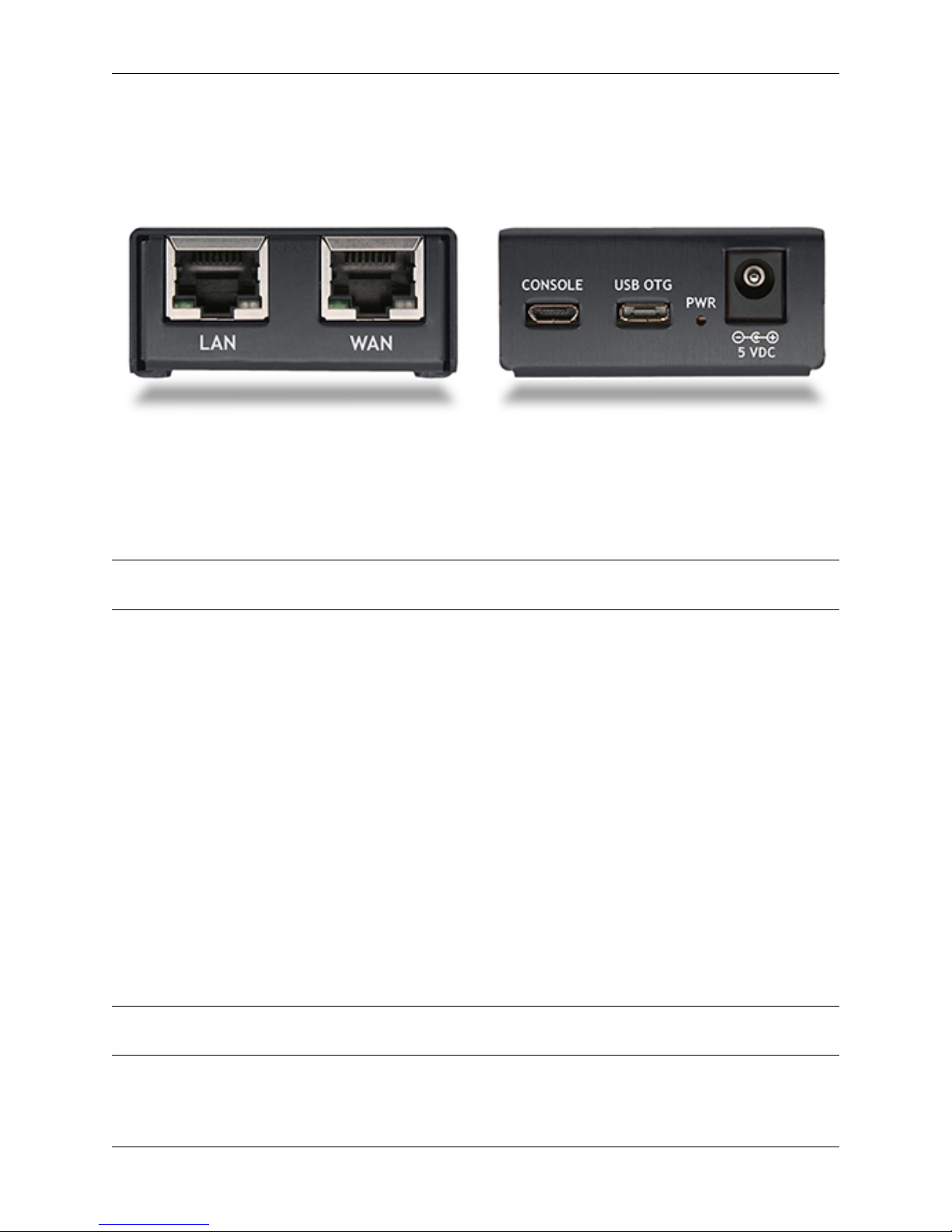
Table of Contents
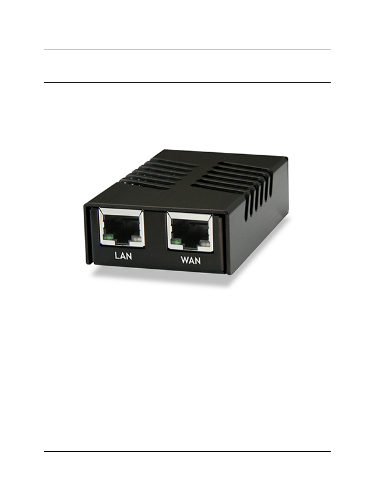
1.1 I/O Ports
Ports are assigned as pictured.
Front
• LAN (cpsw1)
Product Manual, SG-1000
• WAN (cpsw0)
Note: Both the WAN and LAN ports of the pfSense appliance support auto-MDIX and are capable of utilizing either
straight-through or crossover ethernet cables.
Back
• Console (Micro-USB)
• USB OTG
• Status LED
• Power
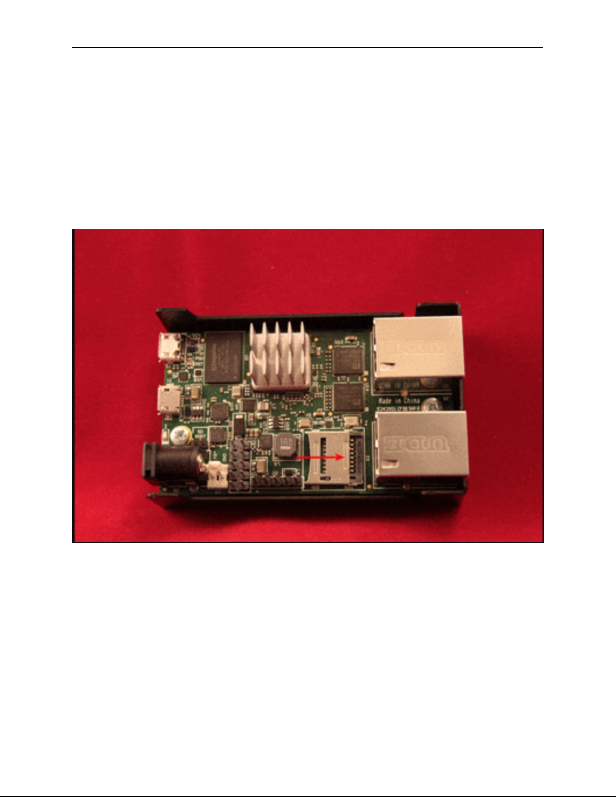
Internal
The Micro-SD card socket uses a sliding lock cover, not a push-style mechanism.
To install a Micro-SD card:
• Gently slide the cover toward the network interface port to unlock it
• Raise the lid
• Place the Micro-SD card in the socket, contacts down
• Gently close the lid
• Slide the cover toward the power connector to lock it in place
Tip: If the cover will not close gently, check the alignment of the Micro-SD card as it may not be settled completely
into the socket in the correct place.
1.1. I/O Ports 3
Product Manual, SG-1000
Fig. 1.1: Installing a Micro-SD card in the SG-1000
1.1. I/O Ports 4
Product Manual, SG-1000
1.2 Getting Started
Tip: Before configuring the pfSense appliance it is best to activate the bundled Gold by following the instructions at
https://www.netgate.com/register/.
The basic firewall configuration begins with connecting the pfSense appliance to the Internet. Neither the modem nor
the pfSense appliance should be powered up at this time.
Establishing a connection to the Internet Service Provider (ISP) starts with connecting one end of an ethernet cable to
the WAN port (shown in the I/O Ports section) of the pfSense appliance.
Warning: The default LAN subnet on the firewall is 192.168.1.0/24. The same subnet cannot be used on
both WAN and LAN, so if the subnet on the WAN side of the firewall is also 192.168.1.0/24, disconnect the
WAN interface until the LAN interface has been renumbered to a different subnet.
The opposite end of the same ethernet cable should be inserted in to the LAN port of the ISP-supplied modem. The
modem provided by the ISP might have multiple LAN ports. If so, they are usually numbered. For the purpose of this
installation, please select port 1.
The next step is to connect the LAN port (shown in the I/O Ports section) of the pfSense appliance to the computer
which will be used to access the firewall console.
Connect one end of thesecond ethernet cable to the LANport (shown in the I/O Ports section) of the pfSense appliance.
Connect the other end to the network connection on the computer. In order to access the web configurator, the PC
network interface must be set to use DHCP, or have a static IP set in the 192.168.1.x subnet with a subnet mask
of 255.255.255.0. Do not use 192.168.1.1, as this is the address of the firewall, and will cause an IP conflict.
1.2.1 Initial Setup
The next step is to power up the modem and the firewall. Plug in the power supply to the power port (shown in the I/O
Ports section).
Once the modem and pfSense appliance are powered up, the next step is to power up the computer.
Once the pfSense appliance is booted, the attached computer should receive a 192.168.1.x IP address via DHCP
from the pfSense appliance.
1.2.2 Logging Into the Web Interface
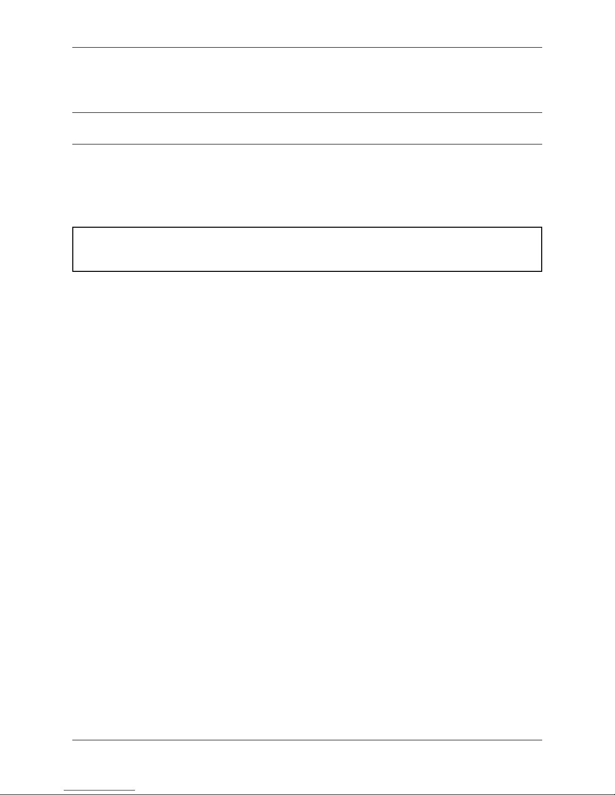
Browse to https://192.168.1.1 to access the web interface. In some instances, the browser may respond with a message
indicating a problem with website security. Below is a typical example in Google Chrome. If this message or similar
message is encountered, it is safe to proceed.
1.2. Getting Started 5
Product Manual, SG-1000
At the login page enter the default pfSense password and username:
Username admin
Password pfsense
Click Login to continue
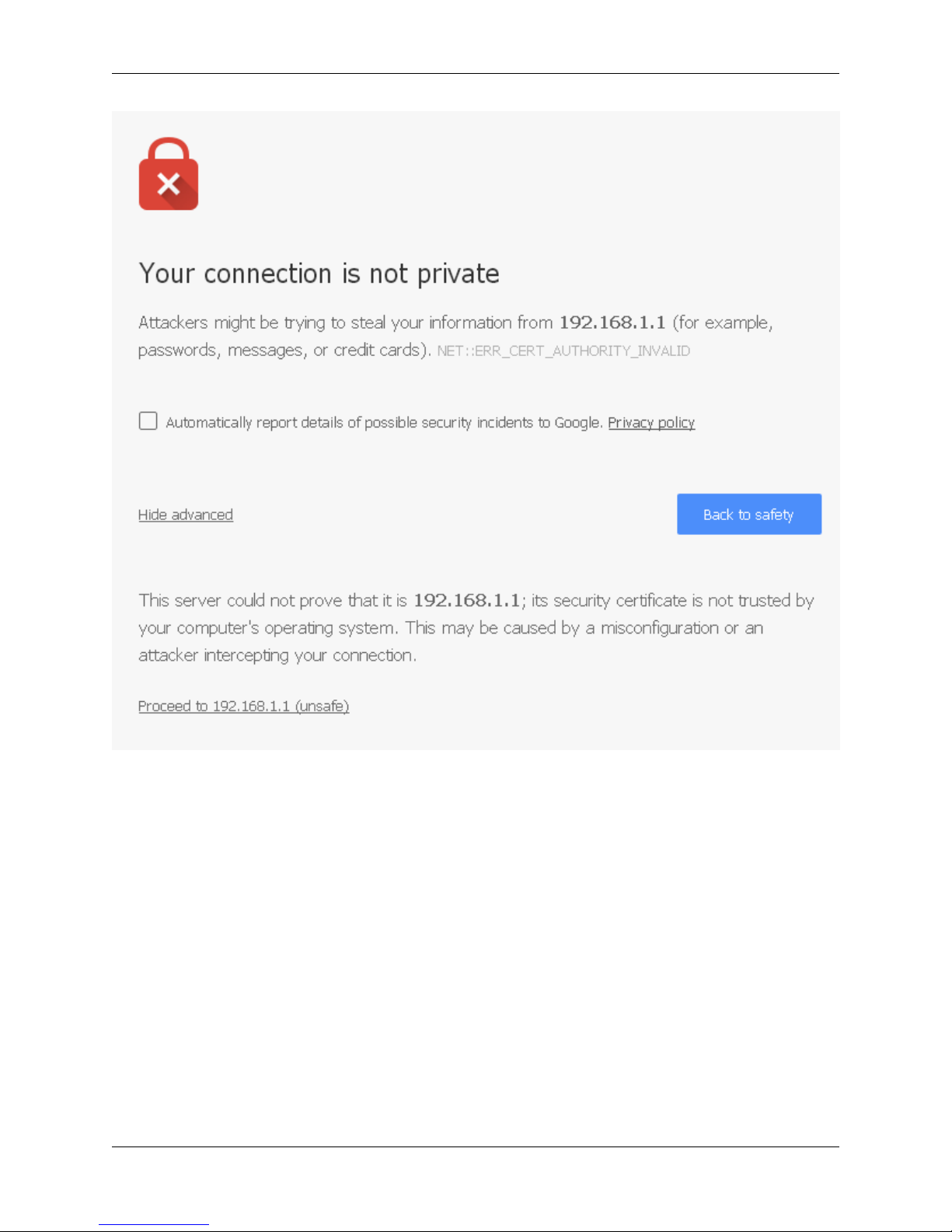
1.2.3 Wizard
Upon successful login, the following is displayed.
1.2. Getting Started 6
1.2.4 Configuring Hostname, Domain Name and DNS Servers
Product Manual, SG-1000
1.2.5 Hostname
For Hostname, anydesired name canbe entered asit does notaffect functionality of the firewall. Assigning a hostname
to the firewall will allow the GUI to be accessed by hostname as well as IP address.
For the purposes of this guide, use pfsense for the hostname. The default hostname, pfsense may be left unchanged.
Once saved in the configuration, the GUI may be accessed by entering http://pfsense as well as http://192.168.1.1
1.2.6 Domain
If an existing DNS domain is in use within the local network (such as a Microsoft Active Directory domain), use that
domain here. This is the domain suffix assigned to DHCP clients, which should match the internal network.
For networks without any internal DNS domains, enter any desired domain name. The default localdomain is used
for the purposes of this tutorial.
1.2.7 DNS Servers
The DNS server fields can be left blank if the DNS Resolver is used in non- forwarding mode, which is the default
behavior. The settings may also be left blank if the WAN connection is using DHCP, PPTP or PPPoE types of Internet
connections and the ISP automatically assigns DNS server IP addresses. When using a static IP on WAN, DNS server
IP addresses must be entered here for name resolution to function if the default DNS Resolver settings are not used.
1.2. Getting Started 7
Product Manual, SG-1000
DNS servers can be specified here even if they differ from the servers assigned by the ISP. Either enter the IP addresses
provided by the ISP, or consider using Google public DNS servers (8.8.8.8, 8.8.4.4). Google DNS servers are
used for the purpose of this tutorial. Click Next after filling in the fields as appropriate.
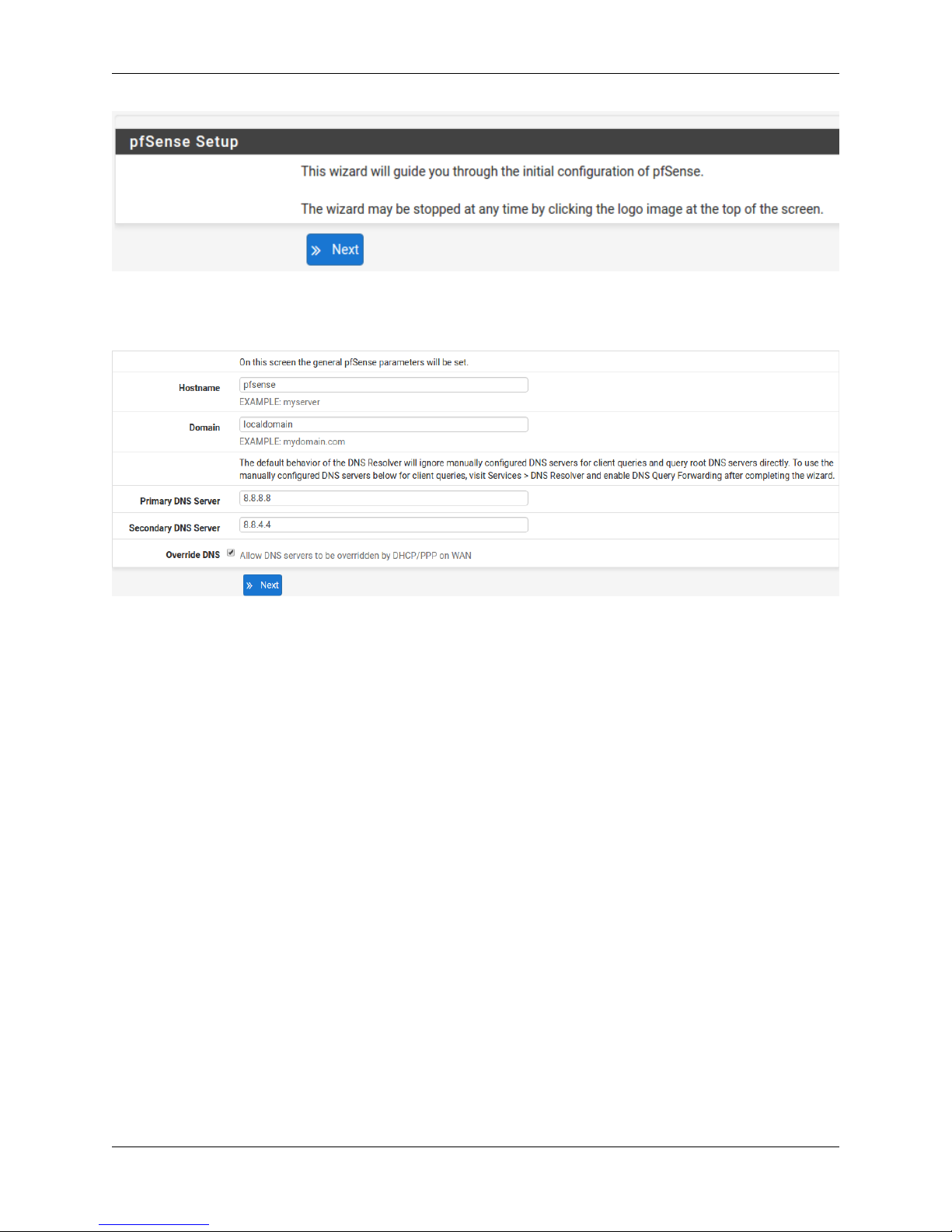
1.2.8 Time Server Configuration
1.2.9 Time Server Synchronization
Setting time server synchronization is quite simple. We recommend using the default pfSense time server address,
which will randomly select an NTP server from a pool.
1.2.10 Setting Time Zone
Select an appropriate time zone for the location of the firewall. For purposes of this manual, the Timezone setting will
be set to America/Chicago for US Central time.
1.2.11 Configuring Wide Area Network (WAN) Type
The WAN interface type is the next to be configured. The IP address assigned to this section becomes the Public IP
address that this network will use to communicate with the Internet.
This depicts the four possible WAN interface types. Static, DHCP, PPPoE and PPTP. One must be selected from the
drop-down list.
Further information from the ISP is required to proceed when selecting Static, PPPoE and PPTP such as login name
and password or as with static addresses, an IP address, subnet mask and gateway address.
1.2. Getting Started 8
Product Manual, SG-1000
DHCP is the most common type of interface for home cable modems. One dynamic IP address is issued from the
ISP DHCP server and will become the public IP address of the network behind this firewall. This address will change
periodically at the discretion of the ISP. Select DHCP as shown and proceed to the next section.
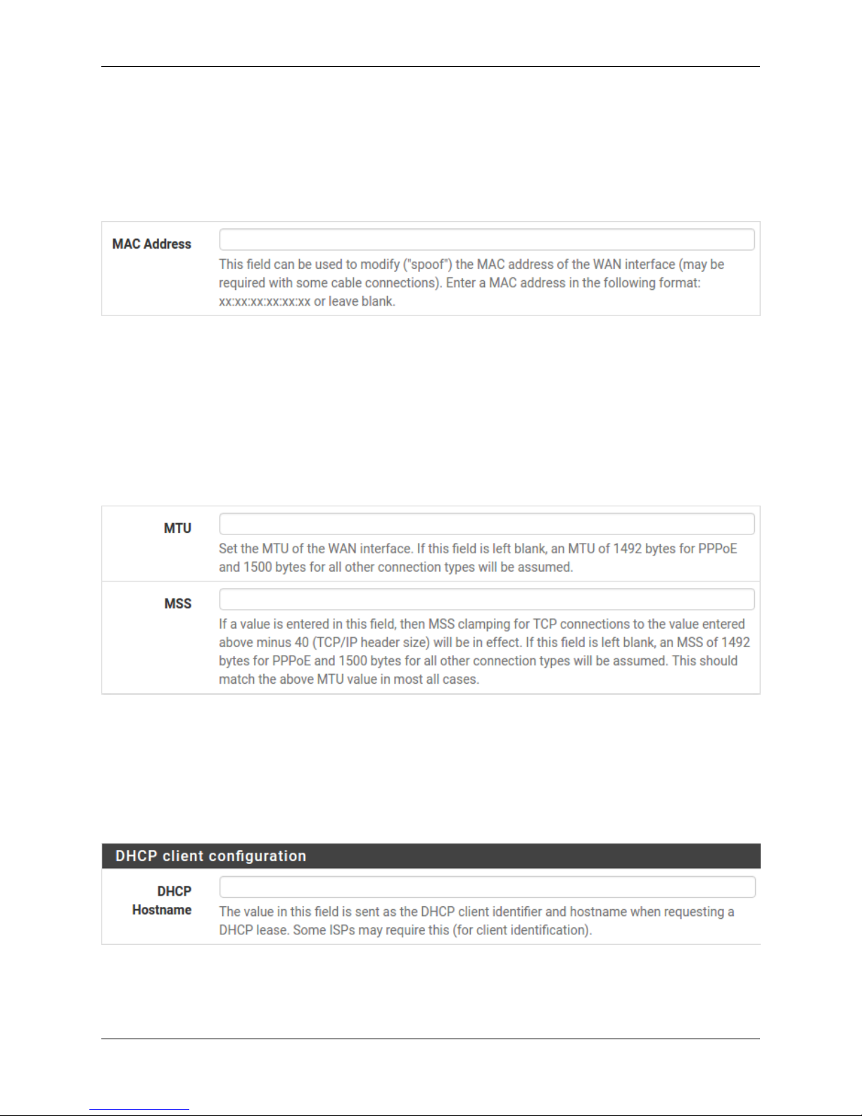
1.2.12 MAC Address
If replacing an existing firewall, the WAN MAC address of the old firewall may be entered here, if it can be determined.
This can help avoid issues involved in switching out firewalls, such as ARP caches, ISPs locking to single MAC
addresses, etc.
If the MAC address of the old firewall cannot be located, the impact is most likely insignificant. Power cycle the ISP
router and modem and the new MAC address will usually be able to get online. For some ISPs, it may be necessary to
call them when switching devices, or an activation process may be required.
1.2.13 Configuring MTU and MSS
MTU or Maximum Transmission Unit determines the largest protocol data unit that can be passed onwards. A 1500byte packet is the largest packet size allowed by Ethernet at the network layer and for the most part, the Internet so
leaving this field blank allows the system to default to 1500-byte packets. PPPoE is slightly smaller at 1492-bytes.
Leave this blank for a basic configuration.
1.2.14 Configuring DHCP Hostname
Some ISPs specifically require a DHCP Hostname entry. Unless the ISP requires the setting, leave it blank.
1.2. Getting Started 9
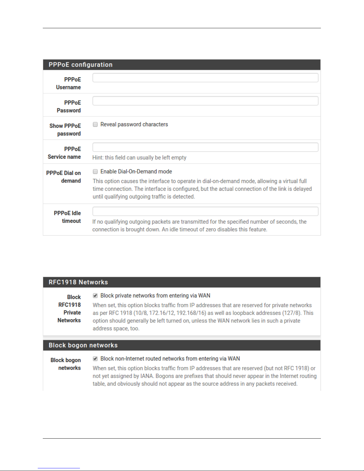
1.2.15 Configuring PPPoE and PPTP Interfaces
Product Manual, SG-1000
Information added in these sections is assigned by the ISP. Configure these settings as directed by the ISP
1.2.16 Block Private Networks and Bogons
When enabled, all private network traffic originating on the internet is blocked.
Private addresses are reserved for use on internal LANs and blocked from outside traffic so these address ranges may
be reused by all private networks.
1.2. Getting Started 10
 Loading...