

Neteon EF23-1-Fm-SC-2, EF23-1-Fs-SC-30, EF23-1G-1Fs-SC-10, EF23-1G-1Fm-SC-550M, EF23-1G-1SFP Installation Manual
Page 1
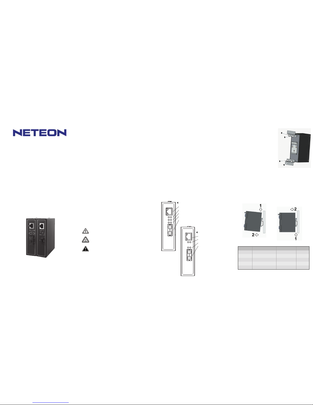
Industrial Ethernet to Fiber Media Convertor
Hardware Installation Guide
Version 1.2
Updated in April, 2015
Introduction Inside the Package
Product Description
EF23 Series
Tel: 886-3-5508137
Fax: 886-3-5508131
www.atop.com.tw
P/N:89900403G
EF23 Series
10/100 Base-T(X) to 100Base-FX Media Converters
EF23G Series
1000Base-T to 1000Base-X Media Converters
Atop Technologies, Inc.
Thank you for c hoosing the Atop Industrial DIN -Rail Ethernet to Fiber Me dia
Converter. The EF23/EF23G Series provide industrial grade media conver-
sion between 10/100Base-T(X ) and 100Base-FX (SC connector ); and
1000Base-T and 1000 BASE-X(SC connector or SFP).
This Guide covers Five product models:
EF23 Series
■
EF23-1-Fm-SC-2:
Fast Ether net 10/100Base-T(X) to 10 0Base-FX Medi a Converter wi th
extended operatin g temperature.
Include 1 10/100M bps RJ45 and 1 100Mbps Multi -mode Optical Fiber.
■
EF23-1-Fs-SC-30:
Fast Ethernet 10/100B ase-T(X) to 1 00Base-FX Me dia Converte r with
extended operatin g temperature.
Include 1 10/100M bps RJ45 and 1 100Mbps Singl e-mode Optical Fiber.
EF23G Series
■
EF23-1G-1Fm-SC-5 50M:
Gigabit Ethernet 1000Base-T to 1000Bas e-X Media Converter with extended
operating tempera ture.
Include 1 1000Mbp s RJ45 and 1 1000M Multi-mod e Optical Fiber.
■
EF23-1G-1Fs-SC-1 0:
Gigabit Ethernet 1000Base-T to 1000Bas e-X Media Converter with extended
operating tempera ture.
Include 1 1000Mbp s RJ45 and 1 1000Mbps Single -mode Optical Fiber.
■
EF23-1G-1SFP:
Gigabit Ethernet 1000Base-T to 1000Bas e-X Media Converter with extended
operating tempera ture.
Include 1 1000Mbp s RJ45 and 1 1000Mbps SFP sl ot.
This device c omplies with Part 15 of the FCC Rules. Ope ration is subject to
the following two conditions:
(1) this device m ay not cause harmful interfe rence, and
(2) this device m ust accept any interference received; including interfer ence
that may cau se undesired operation.
■
Main Pr oduct
■
Atop EF 23/EF23G in dustrial Et hernet Medi a Converter x1
■
Standar d accessori es
■
3-pin Termin al Block (2 ESDVM-03P) x1
Atop P/N: 5070670 1G
■ RJ-45 Port Plugs x1
Ato p P/N: 3990 012G
■ Hardware In stallation Guide (Warran ty card is include) x1
Ato p P/N: 8990 0403G
Optional Accessories
■
3-pin Termin al Block(2E SDVM-03P )
Ato p P/N: 5070 6701G
■
Adapter : 3-pin Termina l block (5. 08 mm) power adaptor,
100-240VAC in put, 1.25A @ 12VDC outpu t, US plug
Ato p P/N: 7010 0000000027G
■ Adapter : 3-pin Termina l block (5. 08 mm) power adaptor,
100-240VAC in put, 1.25A @ 12VDC outpu t, EU plug
Ato p P/N: 7010 0000000028G
Hardware Installation
■
Electrical
Step 1: Unpack the Media Converter, check
to m ake sure no external damages .
Step 2: Connect the powe r adapter/supply (6-48VDC);
It i s normal to see the PWR indi cator on.
Step 3: Connect the RJ-4 5 port to your Ethernet devi ce.
Step 4: Connect the fibe r optical port from EF23 to
anot her EF23 or a switch. Make sure you
conn ect the cable’s Tx to Rx and Rx to Tx.
At this p oint, you should see the
FX_L INK/ACT LED indicator on.
Step 5: Now check to mak e sure your Ethernet device can access the
netw ork.
■
Mechanical
Media Converters are equipped with a DIN-Rail bracket attached onto the
rear panel. Follo w the steps below to fasten the Media Converter to the
DIN-Rail.
Step 1: Tilt the unit slightl y backwards.
Step 2: Fit the unit ove r top the DIN-Rail.
Step 3: Push downwards a nd against the DIN-Rail for locking.
Step 4: Check that the u nit is locked into position.
1. TX Po rt: 10/100 Base-T(X)
2. Green : PWR SPD LED
3. Green : TX_LINK/A CT TX_FDX/C OL LED
4. Green : FX_LINK/A CT FX_F DX/COL LED
5. FX Po rt: 100 Bas e-FX (SC Co nnector)
EF23G Series
1. TX Po rt: 1000 Ba se-T
2. Green : ACT TX_LIN K
3. Green : PWR F X_FDX/COL LE D
4. FX Po rt: 1000 Ba se-X
(SC Connector o r SFP Solt)
EF23 Series DIP Switch Definition
* SPEED is only f or TX
* LFP: Link Fault Pass-through
* This table only a pplies to EF23 series
WARNING:
Disconnect the po wer and allow to cool 5 minu tes before touching.
Never install or work on electrical or cabling duri ng p eriods of
lighting act ivity. Never connect o r disconnect power when hazardous gases are pre sent.
Caution:
CLASS 1 LASER PRO DUCT. Do not stare in to the laser!
DIP Switch
1
2
3
4
5
Mode
TX_DUPLEX_MODE
FX_DUPLEX_MODE
SPEED_MODE
LFP
Auto Negotiation
OFF
Full(default)
Full(default)
100M(default)
Disable(default)
Enable(default)
ON
Half
Half
10M
Enable
Disable
Page 2
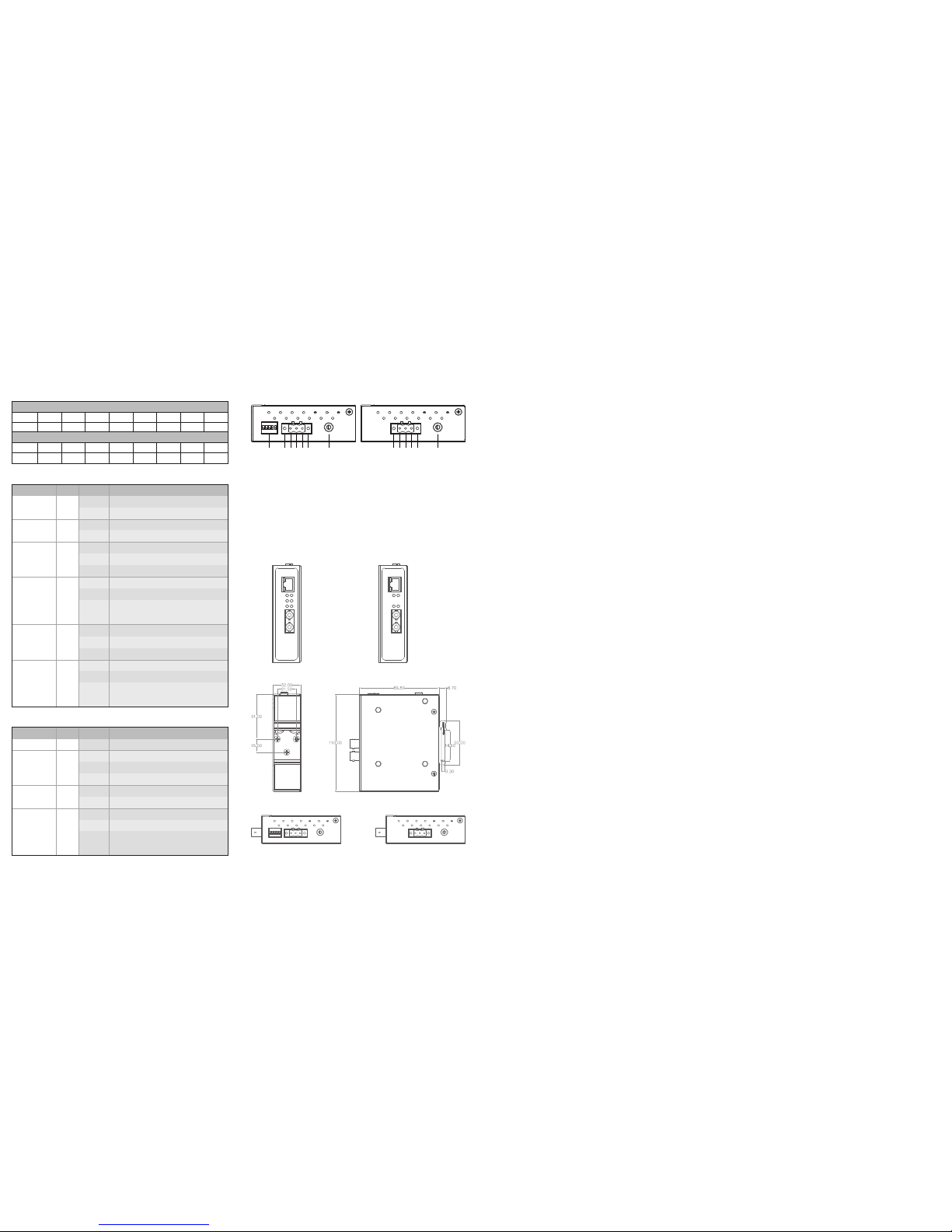
3-pin Terminal Block for power input
Mechanical dimensions(unit=mm)
Front view-EF23 Series
Back view Side view and Panel Mounting View
Front view-EF23G Series
Top view-EF23 Series Top view-EF23G Series
─
7 6 5 4 3 2 1 6 5 4 3 2 1
EF23 Series EF23G Series
Pin Assignment of Network Connections
10/100/1000Base-T(X) Ethernet Port Connection
10/100BASE-T(X)
Pin
Signal1Tx+2Tx-3Rx+4─5─6Rx-7─8─
1. Grou nding screw
2. LOCK
3. Fram e Ground
4. V-
5. V+
6. LOCK
7. DIP S witch
1. Grou nding screw
2. LOCK
3. Fram e Ground
4. V-
5. V+
6. LOCK
LED
PWR
SPEED (SPD)
TX_LINK\ACT
TX_FDX\COL
FX_LINK\ACT
FX_FDX\COL
Color
Green
Green
Green
Green
Green
Green
State
On
Off
On
Off
On
Off
Blinking
On
Off
Blinking
On
Off
Blinking
On
Off
Blinking
Description
System is powered on
System is not powe red on
TX port is running at 100Mbps
TX port is running at 10Mbps
TX port is connect ed
TX port is disconn ected
Data is transmitti ng on this port
TX port is transmi tting in full duplex mode
TX port is transmi tting in half duplex mode
TX port is transmi tting in half duplex mode
and collision has occurred
FX port is connect ed
FX port is disconn ected
Data is transmitti ng on this port
FX port is transmi tting in full duplex mode
FX port is transmi tting in half duplex mode
FX port is transmi tting in half duplex mode
and collision has occurred
1000BASE-T
Pin
Signal
1
BI_DA+2BI_DA-3BI_DB+4BI_DC+5BI_DC-6BI_DB-7BI_DD+8DI_DD-
EF23G Series LED Indicators
LED
ACT
TX_LINK\ACT
PWR
FX_LINK\ACT
Color
Green
Green
Green
Green
State
Blinking
On
Off
Blinking
On
Off
On
Off
Blinking
Description
Data is transmitting on both TX and FX ports
TX port is connect ed
TX port is disconn ected
Data is transmitti ng on this port
System is powered on
System is not powe red on
FX port is connect ed
FX port is disconn ected
FX port is transmi tting in half duplex mode
and collision has occurred
 Loading...