

Page 1

iConn510M Datasheet Rev1.0
www.netdevice.co.kr
NetDevice
Page 2

iConn510M Datasheet Rev1.0
1. Introduction
iConn510M은 임베디드 시스템에 인터넷 통신 기능을 간편하게 탑재할 수 있도록 하기 위해
만들어진 Drop-in 모듈입니다.
이 모듈은 TCP/IP 프로토콜 스택부터, Ethernet MAC, Ethernet PHY, Transformer와 RJ45
connector가 모두 탑재된 제품으로, 단지 사용자의 시스템 내 프로세서와 Local bus로 연결하
고 메모리 제어를 하듯이 데이터를 읽고 쓰기만 하는 것으로 인터넷 통신이 가능하게 됩니다.
또한, 소량 생산을 하는 업체의 경우, MAC address 할당의 어려움을 해소하고자 상용 MAC
address를 내부의 EEPROM에 탑재하였으므로 따로 MAC address를 할당 받을 필요도 없습니
다.
TCP/IP 프로토콜 스택은 위즈네트의 W5100을 사용하였으므로 프로토콜 스택 처리와 관련한
자세한 사항은 위즈네트의 W5100 Datasheet를 참조하기 바랍니다.
1.1. 특징
• 10/100BaseTx 지원
• Half/Full Duplex 지원
• Auto-negotiation, Auto Crossover Detection
• IEEE 802.3/802.3u 호환
• 3.3V with 5V I/O tolerance
• Hardwired Protocol : TCP, IPv4, UDP, ICMP, ARP, PPPoE, IGMP, DLC, MAC, PHY
• Socket 4개 지원
• 상용 MAC address 내장
• DHCP, SMTP, DNS, DDNS 지원
• 2mm Pitch 2x14 header pin type
1.2. 구성 (Block Diagram)
www.netdevice.co.kr
2
NetDevice
Page 3
iConn510M Datasheet Rev1.0
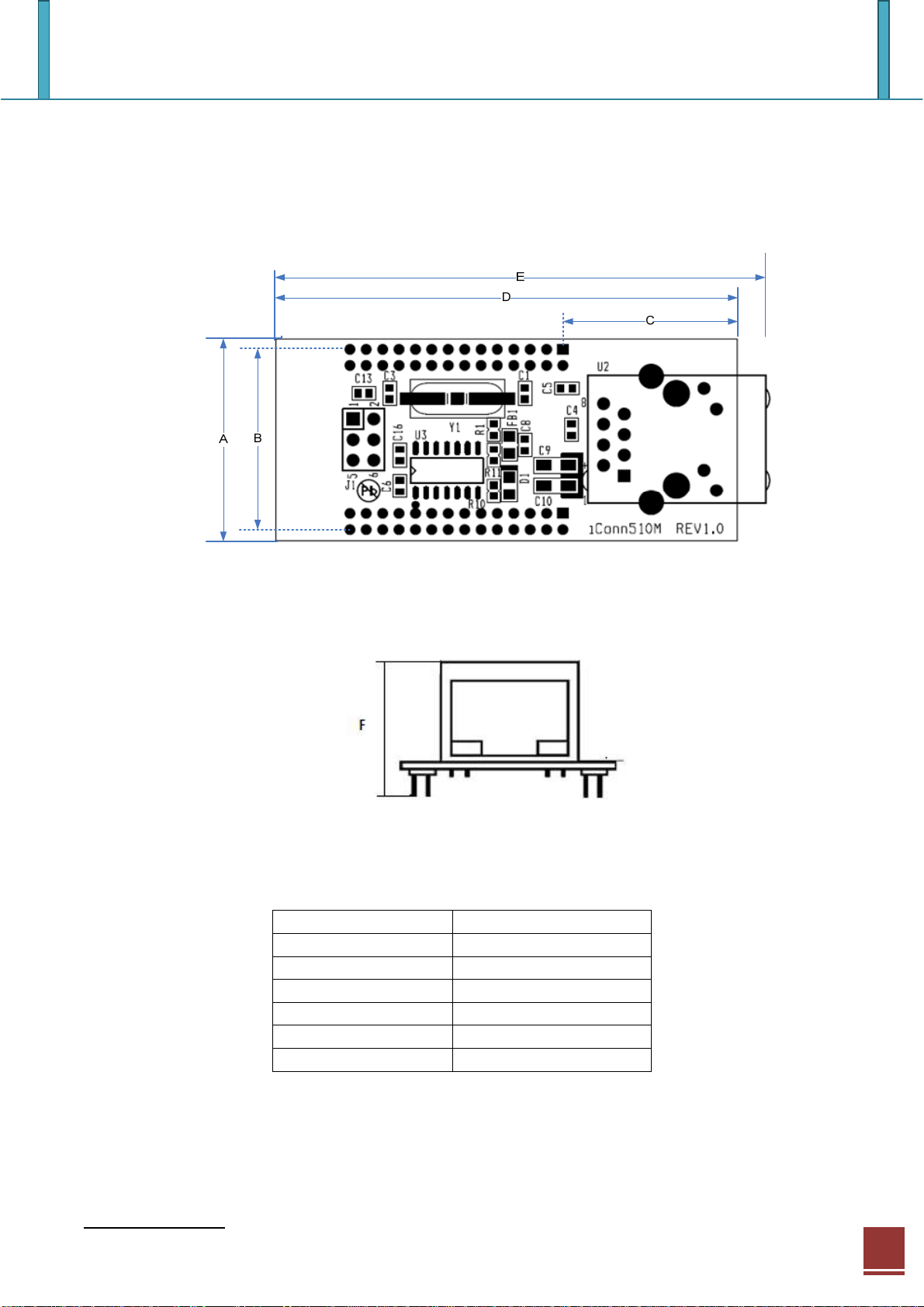
2. Dimension
..
Symbol Dimension(mm)
A 25.0
B 22.5
C 21.5
D 56.0
E 60.0
F 22.0
www.netdevice.co.kr
3
NetDevice
Page 4
iConn510M Datasheet Rev1.0
3. Pin assignment & descriptions
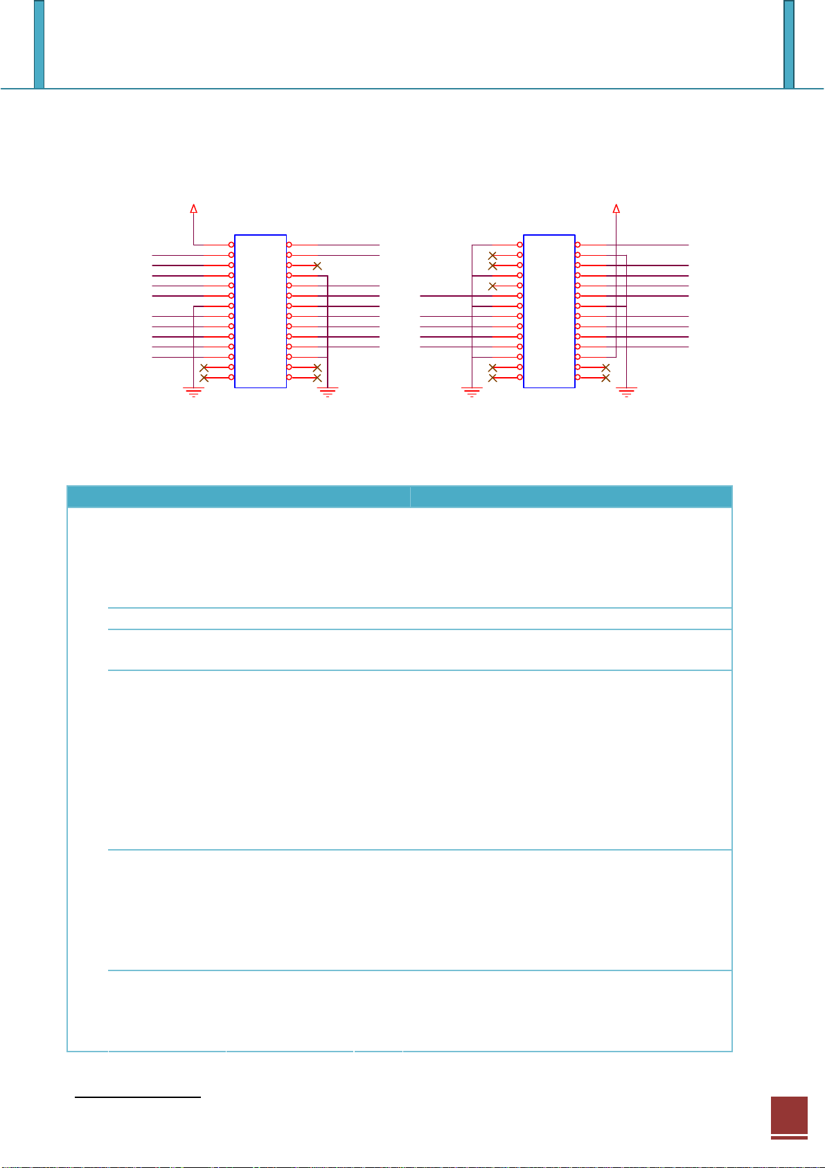
3.1 Pin assignment
3V3D
3V3D
/WR
/CS
A14
A12
A10
A8
A6
A4
A2
A0
JP1
1 2
3 4
5 6
7 8
9 10
11 12
13 14
15 16
17 18
19 20
21 22
23 24
25 26
27 28
HEAD ER 14X2
/INT
/RD
A13
A11
A9
A7
A5
A3
A1
FDX_LED /LINK_LED
D1
D3
D5
D7
JP2
1 2
3 4
5 6
7 8
9 10
11 12
13 14
15 16
17 18
19 20
21 22
23 24
25 26
27 28
HEAD ER 14X2
3.2 Descriptions
PIN Location PIN Name I/O Description
[23:7] A0~A14 I ADDRESS
JP1
Used as Address[14:0] pin
These pins are used to select a register or
memory. Address pins are internally pulled
down.
8, 13, 24 GND I GROUND
1 VCC(3.3V) I POWER
3.3V power supply
2 /INT O INTERRUPT
Active low
This pin indicates that W5100 requires MCU
attention after socket connecting,
disconnecting, data receiving or timeout.
The interrupt is cleared by writing
IR(Interrupt Register) or Sn_IR(Socket nth
Interrupt Register). All interrupts are
maskable.
3 /WR I WRITE ENABLE
Active low
Strobe from MCU to write an internal
register/memory selected by ADDR[14:0].
Data is latched into the W5100 on the rising
edge of this input.
4 /RD I READ ENABLE
Active low
Strobe from MCU to read an internal
register/memory selected by ADDR[14:0].
/RESET
COL_LED
TX_LED
RX_LED
D0
D2
D4
D6
www.netdevice.co.kr
4
NetDevice
Page 5

iConn510M Datasheet Rev1.0
5 /CS I CHIP SELECT
Active low
Chip Select is for MCU to access to internal
registers or memory. /WR and /RD select
direction of data transfer.
6, 25, 26, 27,
28
1, 4, 7, 13,
JP2
14, 23
2 /RESET I RESET
24 VCC(3.3) I POWER
3, 5, 9, 25,
26, 27, 28
[15:22] D0 ~ D7 I/O DATA
6 COL_LED O Collision LED
8 TX_LED O Transmit activity LED
10 RX_LED O Receive activity LED
11 FDX_LED O Full Duplex LED
12 /LINK_LED O Link LED
NC
GND I GROUND
NC
This pin is active Low input to initialize or
re-initialize W5100. By asserting this pin
low for at least 2us, all internal registers will
be re-initialized to their default states.
3.3V power supply
Used as Data[7:0] pin
These pins are used to read and write
register or memory data.
Active low when collisions occur.
Active low indicates the presence of
transmitting activity.
Active low indicates the presence of
receiving activity.
Active low when in full duplex operation.
Active high when in half duplex operation.
Active low in link state indicates a good
status for 10/100M. It is always ON when
the link is OK and it flashes while in a TX or
RX state.
www.netdevice.co.kr
5
NetDevice
 Loading...