

Page 1

N
i
s
d
l
i
r
WL-12 Series
– 3G L
U
ght In
er
ustria
Gu
l M2M
de
Route
Page 2

C
s
e
e
a
i
C
C
g
y
y
m
r
s
p
n
v
u
r
o
f
o
w
t
t
h
o
b
s
d
l
p
e
e
e
,
m
a
s
f
c
n
n
l
e
Cop
right
Cop
right© 2013 NetCo
The
information containe
ent of NetComm Wi
con
Note: This d
Sav
our environment
Wh
n this equipment ha
The
cardboard box, the
tronic equipment alo
elec
se be responsible a
Ple
m Wireless Limited
d herein is proprieta
eless.
ocument is subject t
reached the end o
lastic contained in t
ng with your househ
d protect our enviro
. All rights reserved.
y to NetComm Wirel
change without no
its useful life, it mus
he packaging, and t
ld waste. You may
nment.
ess. No part of this
ice.
be taken to a recyc
e parts that make u
e subject to penalti
ocument may be tra
ling centre and proc
p this device can be
s or sanctions und
nslated, transcribed
ssed separately fro
recycled in accord
r the law. Instead, a
reproduced, in any
domestic waste.
nce with regionally e
k for disposal instru
form, or by any mea
stablished regulatio
tions from your mu
s without prior writt
s. Never dispose of
icipal government.
n
this
Th
s manual co
Net
omm Wireless NWL
Net
omm Wireless NWL
ers the follo
-12-01
-12-02
ing product
:
Net
omm Wireless 3G Li
2
ht Industrial M2M Ro
ter
www.netcommwire
ess.com
Page 3

T
eProPhyPla
vSta
rSysAppAppAppAppAppAppSaf
n
l
.
c
i
s
e
g
.
e
.
d
s
.
e
a
.
m
e
b
v
u
f
e
T
4
u
o
c
t
n
o
g
e
V
1
e
.
.
.
.
M
.
.
.
.
.
.
.
.
.
.
.
.
n
s
M
e
.
.
.
.
.
.
.
.
.
.
.
.
.
.
.
.
.
.
.
.
.
.
.
.
.
.
.
.
.
.
.
.
.
.
R
r
Initial docume
ab
Ov
rview .......
Introduction .............
Target audience ......
Prerequisites ...........
Notation ...................
duct introdu
Product overview ....
Package contents ...
Product features ......
sical dimens
Physical dimension
LED indicators .........
Ethernet port LED in
Interfaces ................
cement of th
Mounting options ....
Ins
tallation and
Powering the router .
Power consumption
Installing the router .
Ad
anced confi
tus ...........
Int
rnet .........
Data Connection .....
Connect on Deman
Operator Settings ....
SIM security setting
LAN .........................
Routing ....................
VPN .........................
vices .........
Se
Dynamic DNS ..........
Network time (NTP) .
Data stream manag
Watchdogs ..............
SNMP ......................
TR-069 .....................
GPS .........................
SMS messaging ......
Diagnostics .............
Sending an SMS Di
tem ..........
Log ..........................
System Configuratio
HTTPS key manage
SSH Key Managem
endix A: Ta
endix B: De
endix C: Mo
endix D: De
Restoring factory d
Recovery mode .......
endix E: HT
endix F: RJ-
ety and prod
nt release
e
................
.....................................
.....................................
.....................................
.....................................
tion ..........
.....................................
.....................................
.....................................
ons and indi
....................................
.....................................
dicators ........................
.....................................
e router ......
.....................................
configuration
.....................................
.....................................
.....................................
uration .......
................
................
.....................................
....................................
.....................................
....................................
.....................................
.....................................
.....................................
................
.....................................
.....................................
..................................
.....................................
.....................................
.....................................
.....................................
.....................................
.....................................
gnostic Command ......
................
.....................................
n ...................................
ent .............................
nt .................................
les ............
ice Mounting
nting Bracke
ault Settings.
fault settings ................
.....................................
PS - Uploadi
5 connector
ct care ......
f C
................
.....................................
.....................................
.....................................
.....................................
................
.....................................
.....................................
.....................................
ators .........
.....................................
.....................................
.....................................
.....................................
................
.....................................
of the 3G Li
.....................................
.....................................
.....................................
................
................
................
.....................................
.....................................
.....................................
.....................................
.....................................
.....................................
.....................................
................
.....................................
.....................................
.....................................
.....................................
.....................................
.....................................
.....................................
.....................................
.....................................
.....................................
................
.....................................
.....................................
.....................................
.....................................
................
Dimensions ..
...............
................
.....................................
.....................................
g a self-sign
................
................
DOCUMENT
nt
................
.....................................
.....................................
.....................................
.....................................
................
.....................................
.....................................
.....................................
................
.....................................
.....................................
.....................................
.....................................
................
.....................................
ht Industrial
.....................................
.....................................
.....................................
................
................
................
.....................................
.....................................
.....................................
.....................................
.....................................
.....................................
.....................................
................
.....................................
.....................................
.....................................
.....................................
.....................................
.....................................
.....................................
.....................................
.....................................
.....................................
................
.....................................
.....................................
.....................................
.....................................
................
................
................
................
.....................................
.....................................
d certificate
................
................
ERSION
Table
- Document Revisio
................
.....................................
.....................................
.....................................
.....................................
................
.....................................
.....................................
.....................................
................
.....................................
.....................................
.....................................
.....................................
................
.....................................
2M router ..
.....................................
.....................................
.....................................
................
................
................
.....................................
.....................................
.....................................
.....................................
.....................................
.....................................
.....................................
................
.....................................
.....................................
.....................................
.....................................
.....................................
.....................................
.....................................
.....................................
.....................................
.....................................
................
.....................................
.....................................
.....................................
.....................................
................
................
................
................
.....................................
.....................................
................
................
................
nt
History
................
.....................................
.....................................
.....................................
.....................................
................
.....................................
.....................................
.....................................
................
.....................................
.....................................
.....................................
.....................................
................
.....................................
................
.....................................
.....................................
.....................................
................
................
................
.....................................
.....................................
.....................................
.....................................
.....................................
.....................................
.....................................
................
.....................................
.....................................
.....................................
.....................................
.....................................
.....................................
.....................................
.....................................
.....................................
.....................................
................
.....................................
.....................................
.....................................
.....................................
................
................
................
................
.....................................
.....................................
................
................
................
................
.....................................
.....................................
.....................................
.....................................
................
.....................................
.....................................
.....................................
................
.....................................
.....................................
.....................................
.....................................
................
.....................................
................
.....................................
.....................................
.....................................
................
................
................
.....................................
.....................................
.....................................
.....................................
.....................................
.....................................
.....................................
................
.....................................
.....................................
.....................................
.....................................
.....................................
.....................................
.....................................
.....................................
.....................................
.....................................
................
.....................................
.....................................
.....................................
.....................................
................
................
................
................
.....................................
.....................................
................
................
................
................
.....................................
.....................................
.....................................
.....................................
................
.....................................
.....................................
.....................................
................
.....................................
.....................................
.....................................
.....................................
................
.....................................
................
.....................................
.....................................
.....................................
................
................
................
.....................................
.....................................
.....................................
.....................................
.....................................
.....................................
.....................................
................
.....................................
.....................................
.....................................
.....................................
.....................................
.....................................
.....................................
.....................................
.....................................
.....................................
................
.....................................
.....................................
.....................................
.....................................
................
................
................
................
.....................................
.....................................
................
................
................
DATE
................
.....................................
.....................................
.....................................
.....................................
................
.....................................
.....................................
.....................................
................
.....................................
.....................................
.....................................
.....................................
................
.....................................
................
.....................................
.....................................
.....................................
................
................
................
.....................................
.....................................
.....................................
.....................................
.....................................
.....................................
.....................................
................
.....................................
.....................................
.....................................
.....................................
.....................................
.....................................
.....................................
.....................................
.....................................
.....................................
................
.....................................
.....................................
.....................................
.....................................
................
................
................
................
.....................................
.....................................
................
................
................
.. 5
........ 5
........ 5
........ 5
........ 5
.. 6
........ 6
........ 6
........ 7
.. 8
........ 8
........ 9
...... 10
...... 11
. 12
...... 12
. 18
...... 18
...... 19
...... 19
. 20
. 21
. 24
...... 24
...... 28
...... 32
...... 33
...... 37
...... 41
...... 51
. 65
...... 65
...... 66
...... 67
...... 69
...... 72
...... 74
...... 75
...... 78
...... 82
...... 85
. 92
...... 92
...... 96
.... 103
.... 107
111
112
114
115
.... 116
.... 117
118
120
121
www
.netcommwireless.com
N
etComm Wireless 3G
Light Industrial M2M
oute
3
Page 4

NetComm Wireless 3G Light Industrial M2M Router
4
www.netcommwireless.com
Page 5

O
n
a
r
o
N
e
c
a
e
u
v
b
h
n
r
g
n
n
e
o
c
t
n
w
f
p
h
M
p
i
e
w
c
e
c
t
e
t
R
r
v
I
trodu
This
document provides
T
rget
This
document is intend
P
ereq
Bef
re continuing with th
otatio
The
following symbols a
The followin
A de
A we
A flat
The followi
The followi
rvi
tion
you all the informati
udien
d for system integra
isites
e installation of your
ice with a working E
browser such as In
ead screwdriver if fi
e used in this user g
note requires atte
g note provides a
g note provides use
w
n you need to set u
e
tors or experienced
3G Light Industrial
hernet network ada
ternet Explorer, Moz
eld terminated pow
uide:
tion.
arning.
ul information.
, configure and use
ardware installers
2M Router, please
ter.
lla Firefox or Google
r is required.
the NetComm Wirel
ho understand tele
onfirm that have the
Chrome.
ss NWL-12 3G Ligh
ommunications term
following:
Industrial M2M Rou
inology and concept
er.
s.
www
.netcommwireless.com
N
etComm Wireless 3G
Light Industrial M2M
oute
5
Page 6

Product introduction
Product overview
Penta-band 3G with quad-band 2G auto-fallback
HSPA+ up to 14.4 Mbps DL
Ethernet port with full passive Power over Ethernet (PoE) support (802.3af) (NWL-12-01 only)
RS232/RS422/RS485 Port and USB 2.0 OTG port
Integrated ZigBee multipoint mesh wireless networking (NWL-12-01 only)
Built in GPS supporting an active or passive GPS Antenna via external SMA connector
Three multi-purpose I/O ports
One dedicated ignition input
Internal diversity antennas with option for external main antenna (autosensing)
Intelligent, Tri-Colour LED display for clear, easy to read modem status information
Extensive device management with support for TR-069, Web GUI and full feature management with SMS
Flexible mounting suitable for in-home use or industrial applications with built-in wall mount and DIN rail mounting options
Package contents
The NetComm Wireless 3G Light Industrial M2M Router package consists of:
1 x 3G Light Industrial M2M Router
2 x 3G antennas
1 x 1.5m yellow Ethernet cable 8P8C
1 x DIN rail mounting bracket
1 x six-way terminal block
1 x quick start guide and safety manual
If any of these items are missing or damaged, please contact NetComm Wireless Support immediately. The NetComm Wireless Support website can be found at:
http://support.netcommwireless.com.
NetComm Wireless 3G Light Industrial M2M Router
6
www.netcommwireless.com
Page 7

r
v
e
s
n
N
e
t
M
3
e
d
y
M
a
a
s
y
i
c
p
y
e
s
w
a
t
p
f
t
a
o
n
e
M
b
o
t
y
m
R
n
A
h
s
r
P
oduct
The
NetComm Wireless
ide state-of-the-art f
pro
hav
an Internet connec
The
3G Light Industrial
erve usage; TR-069
con
ope
management syste
The
NetComm Wireless
eatur
WL-12 3G Light In
atures and versatilit
ion via the use of S
2M Router includes
support for easy m
m allows you to exp
G Light Industrial M
s
ustrial M2M Router i
at an affordable pr
S diagnostics and
many features such
nagement of a grou
nd the feature set b
2M Router meets th
an M2M device de
ce. Compatible with
ommands.
as Dial on Demand
of 3G Light Industri
producing your ow
global demand for
igned by NetComm
network worldwide,
hich provides a me
al M2M routers; and
n custom software a
reliable and cost-e
Wireless to address
he 3G Light Industri
ans to seamlessly c
the ability to functio
plications.
fective M2M device
the rapid growth in
l M2M Router can
nnect or disconnect
as an SSH server t
that successfully cat
2M deployments. I
e managed remotel
the mobile broadba
secure communica
ers to mass deploy
has been designed
even when it does
d connection to
dditionally, t
tions.
ent across busines
to
ot
e
es.
www
.netcommwireless.com
N
etComm Wireless 3G
Light Industrial M2M
oute
7
Page 8

C
P
h
o
g
s
l
s
u
a
o
n
h
i
a
e
ig
H
X
Tab
o
R
M
A
s
s
d
hy
i
ndi
P
ysica
Bel
w is a list of the phy
ic
cat
dime
ical dimensions of t
l d
rs
sions
e 3G Light Industri
m
l M2M Router.
nsi
n
an
Figure 1 – 3G L
(WITHOUT E
Length
Depth
Height
Weight
Net
omm Wireless 3G Li
8
ht Industrial M2M Ro
ter
3G LIG
ht Industrial M2M
T INDUSTRIAL M2
XTERNAL ANTENN
140 mm
103 mm
30 mm
le 2 - Device Dimen
outer Dimensions
ROUTER
S ATTACHED)
ions
www.netcommwireless.com
Page 9

E
e
M
E
s
s
E
r
u
t
h
f
s
1
s
s
s
T
n
u
o
r
A
k
S
a
e
O
R
r
L
D ind
The
3G Light Industrial
icator
2M Router uses 7 L
L
D ICON
Ds to display the c
NAME
rrent system and co
Figure 2 - 3G Lig
COLOUR
nnection status.
t Industrial M2M Ro
STATE
ter LED Indicators
DESCRIPTI
ON
Off
lash
Double
Power
k
Netwo
On
On
Slow fla
On
Blinking
Slow fla
On
Slow fla
Slow fla
Fast flas
1
hing
hing
hing
hing
hing
Power off
Powering up
Power on
Power on in recove
Hardware error
Connected via WW
Traffic via WWAN
Connecting PDP
Registered network
Registering networ
SIM PIN locked
SIM PUK locked
y mode
N
On
On
Signal
strength
On
On
able 3 - LED Indicat
Can’t connect
3G
2G GPRS
GSM only (no GPR
rs
)
1
Th
term “blinking” mean
that the LED may puls
e, with the intervals tha
the LED is on and off
ot being equal. The te
rm “flashing” means th
t the LED turns on and
off at equal intervals.
www
.netcommwireless.com
N
etComm Wireless 3G
Light Industrial M2M
oute
9
Page 10

Signal strength LEDs
The following table lists the signal strength range corresponding with the number of lit signal strength LEDs.
NUMBER OF LIT LEDS SIGNAL STRENGTH
All LEDs unlit < -109 dBm
1 -109 dBm to -101dBm
2 -101 dBm to -91 dBm
3 -91 dBm to -85 dBm
4 -85 dBm to -77 dBm
5 > -77 dBm
Table 4 - Signal strength LED descriptions
LED update interval
The signal strength LEDs update within a few seconds with a rolling average signal strength reading. When selecting a location for the router or connected or positioning an external antenna,
please allow up to 20 seconds for the signal strength LEDs to update before repositioning.
Ethernet port LED indicators
The Ethernet port of the 3G Light Industrial M2M Router has two LED indicators on it.
Figure 3 - Ethernet port LED indicators
The table below describes the statuses of each light and their meanings.
LED STATUS DESCRIPTION
On There is a valid network link.
Green
Blinking There is activity on the network link.
On The Ethernet port is operating at a speed of 100Mbps.
Amber
Off The Ethernet port is operating at a speed of 10Mbps or no Ethernet cable is connected.
Table 5 - Ethernet port LED indicators description
NetComm Wireless 3G Light Industrial M2M Router
10
www.netcommwireless.com
Page 11

n
e
a
t
y
e
u
d
B
o
3
r
m
e
e
e
t
2
h
3
o
o
h
s
a
S
s
D
/
n
n
s
d
n
w
o
e
k
p
p
a
C
R
r
I
terfac
The
following interfaces
s
re available on the
G Light Industrial M
M Router:
Figure 4 - Interface
Main an
enna socket
Auxiliar
antenna socket
GPS ant
enna socket
Six-way
terminal block connector
Reset b
tton
SIM car
slot
RJ45 Po
E Ethernet port
Mini US
2.0 OTG port
Serial p
rt
ITEM
SMA female connec
SMA female connec
SMA female connec
Connect power sou
Refer to the diagra
Press and hold for l
Press and hold for 5
Press and hold for 1
Insert SIM card her
Connect one or sev
supply can serve as
Provides connectivi
Female DB9 port su
tor for main antenna.
tor for auxiliary antenna.
tor for GPS antenna.
ce, ignition and I/O wires
and table on under Step
ss than 5 seconds to reb
to 15 seconds to reboot t
5 to 20 seconds to reset t
.
ral devices via a network
a backup power source if
y for optional external stor
porting 9-wire RS-232, R
ere. Power, ignition and I
of the Installing your dev
ot to normal mode.
recovery mode.
e router to factory default
switch here. This port can
required (PoE available o
ge or a USB Ethernet do
-485 or RS-422 (software
Table 6 – Interface
ESCRIPTION
O wires may be terminate
ice section for correct wiri
settings.
also optionally receive Po
NWL-12-01 only).
gle. Supplies up to 0.5A t
selectable).
on optional terminal bloc
g of the terminal block. O
er over Ethernet (802.3af
connected device.
k and connected to DC in
perates in the 8-40V DC r
PoE) in which case the D
ut jack.
nge.
power
www
.netcommwireless.com
N
etComm Wireless 3G
Light Industrial M2M
oute
11
Page 12
C
P
M
o
e
g
c
s
n
M
a
n
u
m
o
o
o
u
h
i
u
a
t
u
h
o
t
l
o
W
g
e
r
a
u
e
o
w
e
r
o
s
n
l
a
n
la
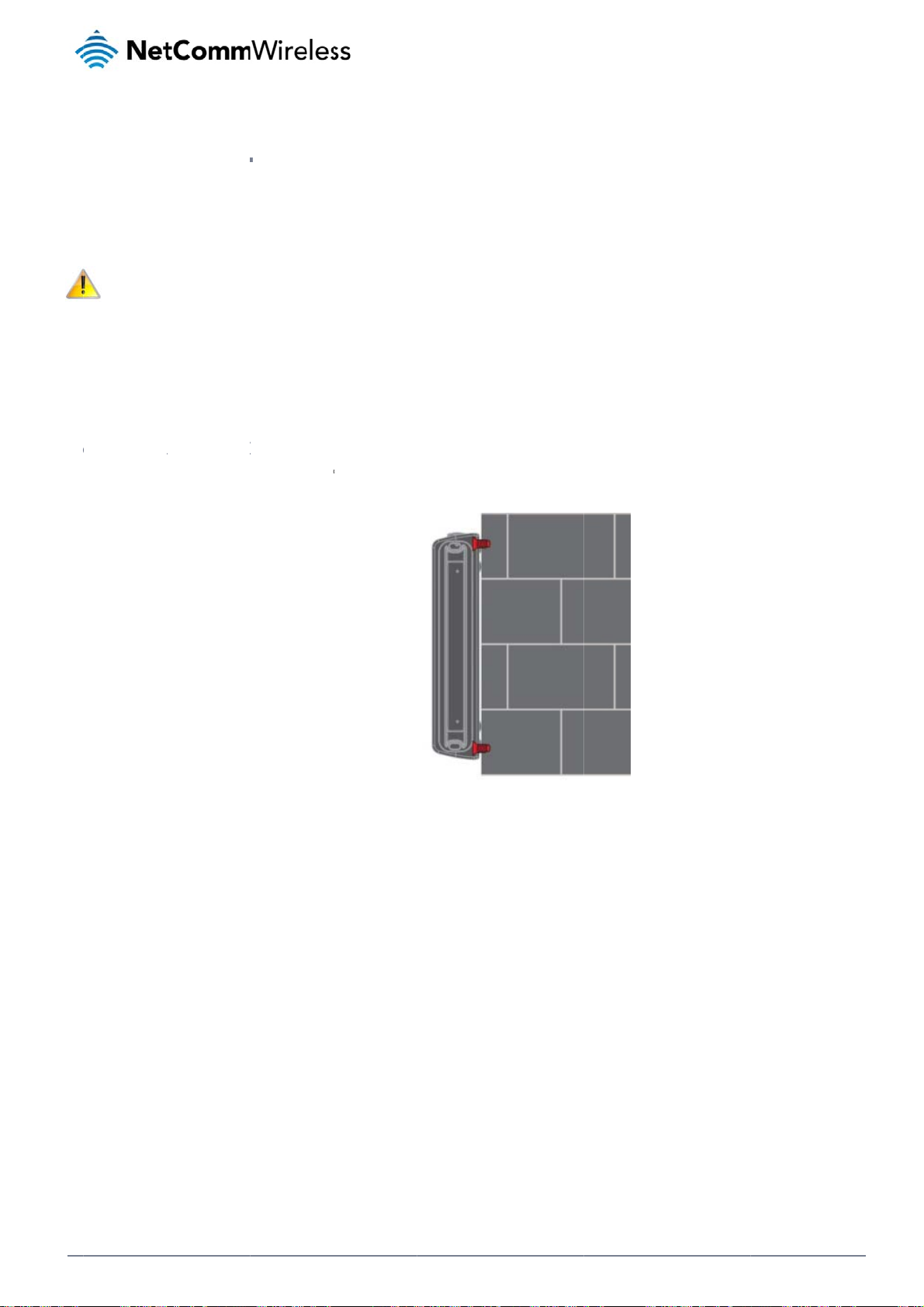
The
two external high-pe
adju
sting the orientation
Note: When
ounti
The
3G Light Industrial
M
unted fl
Wh
n mounted flat agai
e
rformance antennas
of the antennas. If y
electing a location f
g opti
2M router can be q
t against t
st the wall, the 3G L
ent
supplied with the ro
u are unable to get
r the router, allow a
ns
ickly and easily mo
e wall
ght Industrial M2M r
of
ter are designed to
n acceptable signa
least 20 seconds fo
nted in a variety of l
uter has a slimline f
he
provide optimum si
l, try moving the rout
r the signal strength
cations.
orm factor. Use app
ro
nal strength in a wid
r to a different plac
LEDs to update bef
opriately sized scre
ter
range of environm
or mounting it diffe
re trying a different l
s in the mounting h
nts. If you find the
ently.
ocation or connecti
les provided on the
ignal strength is we
g an external anten
base of the unit.
k, try
a.
Figure 5 -
all mount - Flat ag
inst the wall
Net
12
omm Wireless 3G Li
ht Industrial M2M Ro
ter
www.netcommwire
ess.com
Page 13

e
r
m
l
w
I
M
-
w
o
o
d
-
d
t
a
e
-
T
cu
i
n
e
t
q
c
D
R
r
P
rpendicu
If a l
arge surface area is
opriately sized scre
app
C
Section D
The
3G Light Industrial
ar to the
not available, there i
s in the mounting h
N Rail m
2M router easily sli
all
s the option of moun
les provided on the
unt
es onto a C Section
ing the router perpe
back of the unit.
Figure 6 - W
DIN rail so that it is h
ndicular to the wall.
ll mount - Perpendi
orizontally mounted.
his gives the router
lar to the wall
The DIN Rail mounti
a small wall footprin
ng bracket is not re
while remaining se
uired for C Section
urely attached. Use
IN rail mounting.
To
ount the unit on a C
Section DIN rail, sli
e it on as illustrated
below:
Figur
7 - C Section DIN ra
Figure 8
- Mounting the unit o
l mount
a DIN rail
www
.netcommwireless.com
N
etComm Wireless 3G
Light Industrial M2M
oute
13
Page 14

Mounting bracket
The provided mounting bracket provides additional methods of mounting the 3G Light Industrial M2M router.
To attach the mounting bracket, slide it onto the rear of the router as shown in the diagram below:
Figure 9 - Sliding on the mounting bracket
To remove the bracket, press the PUSH button and slide the router off the bracket:
NetComm Wireless 3G Light Industrial M2M Router
14
Figure 10 - Removing the mounting bracket
www.netcommwireless.com
Page 15

R
r
www.netcommwireless.com
NeetComm Wireless 3G Light Industrial M2M
oute
15
Page 16

C
s
s
r
g
m
N
m
M
a
u
r
w
r
e
u
t
d
r
n
a
l
D
c
e
u
m
d
ia
o
a
il
t
t
D
V
U
ing the
By fi
rst attaching the DI
U
ing the
The
3G Light Industrial
ounting b
rail bracket to the
ounting b
2M router may be v
acket for
all, the 3G Light Ind
acket for
rtically mounted to
wall mou
strial M2M router c
Figure 11 – Wa
Top hat
he wall with the bra
ting
n be easily attache
l mount - Mounted v
IN rail m
ket by sliding the br
and removed from
DIN rail bracket
unting
cket onto a top hat
he bracket.
IN rail
Alte
natively, you can att
ch it to the DIN Rail
by using the V ben
Figu
Figur
in the bracket as ill
e 13 - Attaching the
12 - Top hat DIN ra
strated below:
ounting bracket to
mount
e DIN rail using the
bend
Net
omm Wireless 3G Li
16
ht Industrial M2M Ro
ter
www.netcommwireless.com
Page 17

e
t
t
m
u
h
F
u
e
e
e
R
r
D
sk moun
In si
uations where wall
ounts and DIN rails are not required, yo
can simply place t
e 3G Light Industria
igure 14 - Desk mo
l M2M router on a d
nt
sk using its rubber f
et to prevent it from
slipping.
www
.netcommwireless.com
N
etComm Wireless 3G
Light Industrial M2M
oute
17
Page 18

Installation and configuration
of the 3G Light Industrial M2M
router
Powering the router
The 3G Light Industrial M2M router can be powered in one of three ways:
1. Power over Ethernet (802.3af PoE) (available on the NWL-12-01 only)
2. DC power input via 6-pin connector (8-40V DC)
3. DC power input via field terminated power source (8-40V DC)
The green power LED on the router lights up when a power source is connected.
Power over Ethernet (802.3af PoE) (available on the NWL-12-01 only)
Power over Ethernet (PoE) is a method of connecting network devices through Ethernet cable where power and data are passed along a single cable. This may be a desirable method of
powering the device if PoE is available, or if it’s most convenient in the desired installation environment to only have a single cable running to the 3G Light Industrial M2M router.
There are 5 power classes defined in the IEEE 802.3-2005 standard, of which the 3G Light Industrial M2M router is a class 3 device.
CLASS CLASSIFICATION CURRENT POWER RANGE CLASS DESCRIPTION
3 26-30 mA 6.49 – 12.95 W Mid power
Table 7 - PoE power classes
To use PoE to power the 3G Light Industrial M2M router, simply connect your router to a PoE injector or PoE network switch using the bundled yellow Ethernet cable 8P8C.
DC power via 6-pin connector
The DC input jack can accept power from a separately sold DC power supply. Both a standard temperature range DC power supply and an extended temperature range DC power supply are
available to purchase as accessories.
To power the device via DC Power via the 6-pin connector, remove the attached green terminal block from your router and connect the external DC power supply to the router’s green DC power
jack.
DC power via field terminated power source
If an existing 8-40V DC power supply is available, you can insert the wires into the supplied terminal block to power your router. Use a No. 3 flathead screwdriver to tighten the terminal block
screws and secure the power wires, making sure the polarity of the wires are correctly matched, as illustrated below.
NetComm Wireless 3G Light Industrial M2M Router
18
Figure 15 - Locking Power Terminal Block
www.netcommwireless.com
Page 19

a
D
Vi
e
u
o
a
d
w
v
n
r
w
M
h
u
w
t
e
c
w
n
t
q
a
o
o
s
r
e
n
n
m
e
w
u
a
n
n
r
e
e
G
c
o
1
o
o
P
t
u
e
a
g
a
a
d
e
M
o
d
o
)
c
n
d
a
p
w
w
Av
t
y
n
e
y
R
(
ck
e
e
a
y
d
m
a
y
r
a
r
u
n
e
u
e
y
o
i
y
a
e
i
m
o
t
n
l
P
s
a
c
r
n
y
o
R
D
r
r
w
w
r
w
F
ilover po
The
3G Light Industrial
t jack of the router, t
inpu
C input jack, witho
the
ewing po
You
can view the curren
Dev
lopment Kit to acce
To v
iew the router’s pow
s page.
stat
er supp
2M router includes
e router will source
t affecting the route
er sourc
power input mode i
ss this information fo
r source informatio
TERMINAL
+
-
i
I/O
rt (NWL-
upport for connecti
power exclusively fr
’s operation. When
informa
the Advanced stat
r advanced purpos
, log in to the router
Positive wire for power
Ground wire.
Dedicated terminal for
Three terminals used f
Table 8
2-01 only
n of two power sour
m the PoE source. I
oE power is restore
ion
s section of the devi
s (e.g. configuring S
and expand the Adv
DESC
.
ignition detection.
or input/output detection.
- Locking power blo
es at the same tim
the event that pow
, the router automat
ce’s web user interf
MS alerts to inform
anced status box on
IPTION
Please refer to the User G
pin outs
. When a PoE Ether
r from the PoE cabl
cally switches back
ce. This is useful for
ou of the power stat
the status page. Se
ide).
et cable is connecte
is lost, the router w
o receive power fro
remotely monitoring
s of the router).
the Status section
d and DC power is
ill automatically swit
the PoE input sou
the device. You ca
f this manual for mo
lso supplied to the
h to source power f
ce.
also use the Softwa
e information on the
C
om
e
P
wer
To
ssist with power con
con
itions. It’s important
net
ork activity.
A
erage po
I
stalli
Afte
you have mounted
1. Connect e
2. Ensure the
requires d
If you’re us
injector).
indicators
onsu
sumption planning, t
to note that this tabl
er cons
Powered on, idle
Powered on, con
Powered on, con
Peak power draw
g the
he router and conn
uipment that requir
ta access via the 3
ing PoE as the powe
external power sour
n the device with th
ption
he following table su
serves as an indic
mption fi
nd connected to pa
ected to packet dat
ected to packet dat
at maximum 3G mo
outer
cted a power sourc
s network access to
Light Industrial M2
r source, you need t
e is switched on an
se listed on page 8
mmarises average
tion only as the po
ures
STATE
cket data
with average load
with heavy traffic
ule transmission po
Table 9 -
, follow these steps
the Ethernet port of
router. You can co
connect any devic
wait 2 minutes for
of this guide.
ower consumption
er consumed by the
er
erage power consu
to complete the inst
your router. This ma
nnect one device di
s via an available d
our 3G Light Indust
uring the various sta
device is affected b
ption figures
llation process.
be your computer f
ectly, or several dev
ta Ethernet port on
ial M2M router to st
es of the 3G Light I
many variables inc
POWER CONSUM
1.2W
2.0W
4.0W
5.0W
r advanced configu
ces using a network
our PoE power sour
rt up. To check the
dustrial M2M router
luding signal strengt
TION
ration purposes, or
switch.
ce (be it a PoE netw
tatus of your router,
under normal usage
h, network type, and
our end equipment
rk switch or PoE po
compare the LED
hich
er
www
.netcommwireless.com
N
etComm Wireless 3G
Light Industrial M2M
oute
19
Page 20

C
A
o
g
v
M
e
o
e
e
t
a
u
c
w
t
p
d
e
t
n
t
t
,
e
c
n
n
g
dad
M
a
d
g
o
a
b
e
s
t
d
a
r
s
e
g
A
o
d
n
f
u
f
o
m
l
y
a
a
d
The
3G Light Industrial
To l
g in to the web-bas
1. Open a we
2. Enter the l
use one of
an
2M Router comes
d user interface rou
b browser (e.g. Inter
gin username and
the default account
ed
ith preconfigured se
er:
net Explorer, Firefox
assword. If this is th
etails to log in.
co
tings that should sui
Safari), type http://1
Figure 16 – Log i
first time you are lo
fi
t most customers. F
92.168.1.1 into the
prompt for the web-
gging in or you have
ur
r advanced configu
ddress bar and pre
ased user interfac
not previously confi
tio
ation, log in to the w
s Enter. The web-ba
ured the password
eb-based user inter
sed user interface l
for the “root” or “ad
ace of the router.
g in screen is displa
in” accounts, you c
ed.
n
Note: To acc
For security r
then Adminis
The
Status page is displ
ss all features of th
easons, we highly re
ration page.
yed when you log i
ADMI
Username:
Password:
router, you must us
commend that you
successfully.
N MANAGER ACCO
Table 10 -
the root manager
hange the passwor
UNT
a
min Us
min Pa
anagement accoun
ccount.
s for the root and a
ROOT MANAGER
rname: ro
sword: a
login details
min accounts upon i
CCOUNT
min
nitial installation. Yo
can do so by navig
ating to the System
nd
Net
20
omm Wireless 3G Li
ht Industrial M2M Ro
ter
www.netcommwire
ess.com
Page 21

S
o
u
s
e
d
a
t
a
g
n
e
p
u
y
e
a
n
T
R
w
r
tat
The
status page of the w
Syst
em information, LAN
butt
ns to show or hide t
s
eb interface provide
details, Cellular con
hem. Extra status bo
system related info
nection status, Pack
xes will appear as a
rmation and is displ
t data connection s
ditional software fe
yed when you log i
atus and Advanced
tures are enabled (
to the 3G Light Ind
status details. You c
.g. VPN connectivit
strial M2M router m
n toggle the sectio
).
nagement console.
s from view by click
he status page sho
ing the or
s
Fi
ure 17 - The Status
age
www
.netcommwireless.com
N
etComm Wireless 3G
Light Industrial M2M
oute
21
Page 22

ITEM DEFINITION
System information
System up time The current uptime of the router.
Board version The hardware version of the router.
Serial Number The serial number of the router.
Software The software version number running on the router.
Model The type of phone module and the firmware version of the module.
Firmware version The firmware revision of the phone module.
IMEI The International Mobile Station Equipment Identity number used to uniquely identify a mobile device.
LAN
IP The IP address and subnet mask of the router.
MAC Address The MAC address of the router.
Ethernet Port Status Displays the current status of the Ethernet port and its operating speed.
Cellular connection status
SIM Status Displays the activation status of the router on the carrier network.
Signal strength (dBm) The current signal strength measured in dBm
Network registration status The status of the router’s registration for the current network.
Operator selection The mode used to select an operator network.
Current operator The current operator network in use.
Roaming status The roaming status of the router.
Allowed bands The bands to which the router may connect.
Current band The current band being used by the router.
Coverage The mobile equipment identifier (MEID) of the router, a unique code for identifying devices on a CDMA network.
WWAN Connection Status
Profile name The name of the active profile.
Status The connection status of the active profile.
Default profile Indicates whether the current profile in use is the default profile.
WWAN IP The IP address assigned by the mobile broadband carrier network.
DNS server The primary and secondary DNS servers for the WWAN connection.
APN The Access Point Name currently in use.
Connection uptime The length of time of the current mobile connection session.
Advanced status
Mobile country code The Mobile Country Code (MCC) of the router.
Mobile network code The Mobile Network Code (MNC) of the router.
Signal quality (Ec/N0) A measurement of the portion of the received signal that is usable. This is the signal strength minus the signal noise level.
Received signal code power (RSCP) The power level of the signal on the current connection’s particular channel.
Power input mode Displays whether power is currently being sourced from the PoE Ethernet port or from the DC input jack (PoE available on NWL-12-01 only)
HSUPA category Displays the HSUPA category (1-9) for the current uplink
HSDPA category Displays the HSDPA category (1-8) for the current downlink.
SIM ICCID The Integrated Circuit Card Identifier of the SIM card used with the router, a unique number up to 19 digits in length.
Primary scrambling code (PSC) The Primary scrambling code for the current signal.
DC input voltage Displays the current voltage of the power input source provided via the DC Input jack
Location area code (LAC) The ID of the cell tower grouping the current signal is broadcasting from.
NetComm Wireless 3G Light Industrial M2M Router
22
www.netcommwireless.com
Page 23

C
a
A
t
m
t
h
n
m
r
e
e
R
r
IMSI
Cell ID
Channel number (UARF
The Internation
N)
The channel nu
unique code
l mobile subscriber identit
hat identifies the base sta
ber of the current 3G/2G
Table
y is a unique identifier of t
ion from within the locatio
connection.
11 - Status page ite
e user of a cellular netwo
area of the current mobil
details
k.
network signal.
www.netcommwireless.com
N
etComm Wireless 3G Light Industrial M2M
oute
23
Page 24

Internet
The Internet section provides configuration options for Wireless WAN, LAN, Routing and VPN connectivity.
Data Connection
The data connection page allows you to configure and enable/disable the connection profile. To access this page, click on the Networking menu, and under the Wireless WAN menu, select the
Data Connection item.
NetComm Wireless 3G Light Industrial M2M Router
24
Figure 18 – Data connection settings
www.netcommwireless.com
Page 25

o
w
a
c
f
u
a
m
c
c
g
h
h
n
o
d
o
y
n
d
n
p
u
d
e
m
t
a
n
e
g
s
2
w
u
t
e
.
-
o
s
e
te
t
a
g
o
o
N
o
r
t
w
o
a
e
g
e
e
m
t
o
g
o
l
r
R
d
a
n
r
Data connection
Transparent Bridge (PPP
Profile name list
Default
Status
APN
Username
Roaming settings
Allow data roaming
C
nnecting
The
router supports the
een different conne
bet
For
dvanced networkin
sele
ting two profiles wit
con
lict and result in neit
ens
re smooth operatio
ITEM
oE)
to the mo
onfiguration of up t
tion settings.
purposes, you ma
h the same APN as t
er profile establishi
.
Toggles the tra
Sets the corres
Toggles the cor
The APN config
The username
When set to ON
router will deny
bile broa
six APN profiles; th
activate a maximu
his can cause only o
g a connection. We
sparent bridge function o
onding profile to be the d
esponding profile on and
red for the correspondin
sed to log on to the corre
, the router will allow local
network access to data se
Table 1
band net
se profiles allow yo
of two profiles simu
ne profile to connec
recommend that the
and off.
fault gateway for all outb
off. If your carrier support
profile.
ponding APN.
devices to access the Wir
rvices when roaming onto
- Data connection i
ork
to configure the se
ltaneously (depend
. Similarly, activatin
two active connecti
DEFINITIO
und traffic except traffic f
it, two profiles may be tu
less WAN network when t
a foreign network. This se
m details
tings that the router
nt on network supp
two profiles which
n profiles have diff
r which there are configur
ed on simultaneously.
e MachineLink 3G is roa
ting is ON by default.
ill use to connect to
rt). When activating
re both configured t
ring, manually confi
ed static route rules or pr
ing onto a foreign networ
the 2G/3G network
wo connection profi
automatically dete
ured APNs to avoid
file routing settings.
. When set to OFF, the
and switch easily
es, you should avoi
mine an APN can c
connection issues a
use a
d
M
nually c
To
anually configure a
1. Click the E
nfiguring
connection profile:
it button correspon
a connec
ing to the Profile th
ion profil
t you wish to modify
Figure 19
. The data connectio
- Data connection pr
n profile settings pa
file settings
e is displayed.
www
.netcommwireless.com
N
etComm Wireless 3G
Light Industrial M2M
oute
25
Page 26

2. Click the Profile toggle key to turn the profile on. Additional settings appear.
Figure 20 - Data connection settings - Profile turned on
3. In the Profile name field, enter a name for the profile. This name is only used to identify the profile on the router.
4. Ensure that the Automatic APN selection toggle key is set to off. If it is not, click it to toggle it to the off position.
5. In the APN field, enter the APN Name (Access Point Name) and if required, use the Username and Password fields to enter your login credentials.
6. Next to Authentication type, select the either CHAP or PAP depending on the type of authentication used by your provider.
7. The Reconnect delay field specifies the number of seconds to wait between connection attempts. The default setting of 30 seconds is sufficient in most cases but you may modify it
to wait up to 65535 seconds if you wish.
8. The Reconnect retries field specifies the number of times to attempt to connect to the network if the router fails to establish a connection. It is set to 0 by default which causes the
router to attempt to reconnect indefinitely.
9. The Metric value is used by router to prioritise routes (if multiple are available) and is set to 20 by default. This value is sufficient in most cases but you may modify it if you are
aware of the effect your changes will have on the service.
10. The MTU field allows you to modify the Maximum Transmission Unit used on the connection. Do not change this unless instructed to by your carrier.
11. Use the NAT Masquerading toggle key to turn NAT Masquerading on or off. NAT masquerading, also known simply as NAT is a common routing feature which allows multiple LAN
devices to appear as a single WAN IP via network address translation. In this mode, the router modifies network traffic sent and received to inform remote computers on the internet
that packets originating from a machine behind the router actually originated from the WAN IP address of the router’s internal NAT IP address. This may be disabled if a framed
route configuration is required and local devices require WAN IP addresses.
12. For advanced networking such as using dual simultaneous PDP contexts, you may wish to configure a particular profile to route only certain traffic via that profile by configuring a
custom address and mask of traffic to send via that profile. To do this, in the Profile routing settings section, enter the Network address and Network mask of the remote network. If
you do not want to use this feature, or are unsure, please leave these fields blank, which will not designate any particular traffic to be routed via this profile. For more information on
configuring Profile routing settings, see the Setting a default gateway with two active connection profiles example.
NetComm Wireless 3G Light Industrial M2M Router
26
www.netcommwireless.com
Page 27

o
r
n
g
a
c
s
u
f
d
c
e
o
d
a
p
n
t
e
s
o
s
o
R
w
r
13. Click the S
C
nfirming
Afte
configuring the pa
con
ection, the WWAN
usa
e button.
ve button when yo
a success
ket data session, an
ection is expanded
have finished enteri
ul conne
ensuring that it is
showing the details
ng the profile details
tion
nabled, click on the
f the connection an
Figure 21 - P
.
Status menu item at
the Status field dis
cket data connectio
the top of the page
lays Connected. To
status section
o return to the Statu
see details on the c
page. When there i
nnected session, y
a mobile broadban
u can click the Sho
d
data
www
.netcommwireless.com
N
etComm Wireless 3G
Light Industrial M2M
oute
27
Page 28

C
C
nWhe
o
c
g
t
o
g
n
u
e
a
m
g
(
n
i
m
n
b
t
v
S
e
W
n
a
p
E
f
o
r
e
r
s
d
t
u
e
a
e
l
onnec
The
connect on demand
ection to the mobile
con
n the data connecti
Note: When i
C
nfigurin
To
onfigure Connect on
1. Click the N
2. On the Co
on D
feature keeps the P
broadband network
n is established, the
nteresting packets a
Connect
demand:
etworking menu ite
nect on demand pa
mand
cket Data Protocol
. When a packet of i
router monitors traff
rrive, the recovery ti
on Dema
from the top menu
e, click the Connec
PDP) context deacti
terest arrives or an
c and terminates th
e for the wireless
d
ar.
on demand toggle
ated by default whil
MS wake-up comm
link when it is idle.
AN connection is a
key so that it is ON.
e making it appear t
nd is received, the
proximately 20-30 s
xtra options appea
locally connected
outer attempts to es
conds.
. See the following s
evices that the rout
tablish a mobile bro
ub-sections for furth
r has a permanent
dband data connec
r instructions.
tion.
Figure 22 - Co
nect on demand con
iguration option
Net
omm Wireless 3G Li
28
ht Industrial M2M Ro
ter
www.netcommwire
ess.com
Page 29

e
o
f
e
x
n
x
m
w
r
m
r
n
r
e
N
d
d
o
c
p
s
p
s
w
e
d
r
t
k
y
s
p
w
C
e
m
t
d
t
D
g
a
t
a
a
o
i
m
o
ty
t
o
e
o
d
g
g
d
e
c
n
k
o
t
n
n
e
o
b
e
p
d
u
D
t
r
t
R
u
m
e
d
S
t
r
d
S
tting the
In s
me situations, you
this
eature, click Enable
host
on the specified po
outer to
ay wish to have the
dial port filter and e
t(s) will trigger the c
ial a conn
internet connection
nter the port numbe
nnection to dial. No
ection wh
isabled except at ti
or list of port numbe
e that when this fea
en traffic
es when outbound
rs separated by co
ure is enabled, the
s detecte
traffic to a particular
mas. When you sel
ptions to ignore spe
on speci
external host’s port
ct this option, all out
ific packet types ar
fic ports
r range of ports is s
bound ICMP/TCP/U
not available.
nt to the router. To
P packets to any re
se
ote
You
can allow Microsoft
to s
t it to ON.
E
cluding c
Dep
ending on your envi
TCP
, UDP or ICMP pack
ected device.
con
etwork awareness (
ertain pa
onment, you might
ts. When any of the
NCSI) traffic through
ket types
refer to exclude cert
e options are chec
Figure 23 – Dial on
but if you prefer tha
Figure 24 -
from trig
ain types of traffic p
ed the router will no
Figure 25 – Di
emand - Data activi
t they do not trigger
Ial on demand - Ign
ering th
ssing through the r
dial a connection w
l on demand - Exclu
triggered connectio
he connection, clic
re NCSI traffic
connecti
uter from triggering
en that type of outb
ing IP protocols
the Ignore Microsoft
n to dial
he data connection.
und destined data
network awareness
You can tell the rou
packet reaches the
(NCSI) traffic toggl
er to ignore outboun
outer from a locally
key
E
cluding c
So
e devices may gene
Net
ork Time Protocol (
that
application type an
ertain ap
rate general traffic a
TP) or Microsoft net
will not dial a conn
lication t
a part of normal o
ork awareness (N
ction when this data
pes from
eration which you m
SI) traffic from devic
type is received.
triggerin
ay not want to trigge
es behind the router
the con
r the data connectio
. When you check th
ection to
. You can set the ro
box for these optio
ial
uter to ignore Domai
ns, it tells the router
Name System (DN
o ignore the reques
),
from
Figure 26 - Dial
n demand - Excludin
application types
www
.netcommwireless.com
N
etComm Wireless 3G
Light Industrial M2M
oute
29
Page 30

Setting timers for connection and disconnection
The router has a number of timer settings which let you determine when a connection is dialled and when it is disconnected.
Figure 27 – Dial on demand - Connect and disconnect timers
OPTION DESCRIPTION
On data activity, stay online for at least
After connecting, stay online for at least
After hanging up, don’t redial for After a connection has been disconnected, you can tell the router to rest for a period of time before re-dialling.
Disconnect regardless of traffic after Forces the router to disconnect the connection regardless of the traffic passing through it. The default setting is never.
Connect regularly, every / Randomise connect frequency by
up to
When traffic as per the configured settings above appear, the router will either continue to stay online, or dial a connection and will not disconnect it
for the specified time period (min. 1 minute, max. 1 hour). This timer is continuously reset throughout the duration of a dial-up session, whenever
data activity is detected matching the rules above.
This timer configures the router to not hang-up the connection for the specified time period after initially dialling the connection. This setting cannot
be less than the keep online period above. This timer affects the connection only once per dial up session, at the beginning of the session.
If you want to have the router dial a connection at regular intervals, use Connect regularly, every to specify the interval between dials. Setting this to
never effectively disables this option.
The router also features the ability to randomise the time at which the first dial action is performed. This is useful in situations such as where you
have numerous routers in an area where a power outage has occurred. Setting a random dial time helps to reduce network congestion when all the
routers are powered on so they do not all try to connect simultaneously.
When it is set to at least 2 minutes, you are able to configure the router to randomise the time it begins to dial. The randomised dial timer only affects
the initial dial after the unit powers on or after the settings are saved. For example, if you configure the router to dial every 2 minutes with a
randomised dial time of 1 minute, the router will dial the initial connection at a time greater than 2 minutes, but less than 3 minutes. After the first dial,
the router will dial the connection exactly every 2 minutes.
Table 13 - Connect on demand - Connect and disconnect timers descriptions
Verbose mode
The router provides the option of logging all the data activity which matches the settings for the Dial on demand feature for advanced troubleshooting purposes. To enable the logging of the Dial
on demand feature, click the Enable verbose mode toggle key to switch it ON. See the System log section for more information.
Figure 28 – Dial on demand - Verbose logging configuration
NetComm Wireless 3G Light Industrial M2M Router
30
www.netcommwireless.com
Page 31

a
r
e
M
S
o
e
c
u
w
/
o
o
c
o
a
u
n
a
h
o
u
e
e
e
s
e
h
c
R
o
n
r
M
nually c
The
e may be times whe
whe
never necessary. Th
Wh
n you have finished
S
S Wake
The
router can also be
Wake up function.
SM
nnecting
n you need to either
online status of the
onfiguring the opti
p
oken up by means
disconne
force a connection t
connection is displ
ns for the Dial on de
f an SMS message
ting
be made or force a
yed above the butto
Figure 29 - Di
and feature, click t
sing the SMS diagn
disconnection man
ns.
l on demand - Onlin
he Save button at th
stics feature by sen
ally. You can use th
/Offline control
bottom to save you
ding a zero byte cla
Manual connect an
r changes.
s 1 flash SMS. See t
d Manual disconne
he Diagnostics secti
t buttons to do this
n for details on usi
g the
www
.netcommwireless.com
N
etComm Wireless 3G
Light Industrial M2M
oute
31
Page 32

C
O
n
e
e
k
p
e
g
o
a
e
v
i
r
n
a
A
M
M
M
M
M
a
e
C
s
e
a
o
u
n
e
u
u
y
c
a
n
e
p
w
o
u
c
h
t
o
u
e
b
a
f
Fi
m
n
o
o
a
n
h
o
b
w
m
c
p
p
n
u
w
t
h
u
t
a
t
v
e
l
y
h
perat
The
Operator settings p
Note: In ord
already acti
You
may want to do this
con
ect on the network f
Use
the Change band d
The
following band setti
It is
ot necessary to ch
d band selection is
forc
Wh
n All bands is select
The
GSM All and the W
Clic
the Save button to
All B
GSM
WCD
GSM
GSM
GSM
GSM
WCM
WCD
WCD
WCD
WCD
r Setti
ge enables you to s
r to change the cell
e.
if you’re using the ro
requencies that suit
op down list to sele
gs options are avail
nds
All
A All
850
900
1800
1900
DA 850
A 900
A 800
A 1900
A 2100
nge the default setti
no longer available.
d, the router attem
DMA all options allo
ave and apply your
gs
lect which frequen
lar band settings, t
ter in a country with
our requirements.
t the band you wish
ble:
g of All bands in m
ts to find the most s
you to force the d
selection.
y band you will use
e data connection
multiple frequency
o use.
st cases. In fact, loc
itable band based
vice to lock to either
or your connection
igure 30 - Band setti
ust be disabled. W
etworks that may n
king to a particular
n the available net
2G networks only, o
nd enables you to s
gs
en you access this
t all support High S
and can cause con
orks for the inserted
r 3G networks only.
an for available net
age, you are promp
eed Packet Access
ection difficulties if t
SIM card.
ork operators in yo
ed to disable the d
(HSPA). You can sel
he device is moved
r area.
ta connection if it is
ect the router to onl
o a location where t
e
O
erator s
The
operator settings fe
ct operator mode fr
Sel
ttings
ture allows you perf
m automatic to Man
rm a scan of availa
al then click the sc
le networks, and to
n button. This opera
ptionally lock to a p
tion can take a few
articular network ret
inutes and requires
rned by the network
that the packet data
scan. To scan for a
session be disconn
ailable networks, se
cted prior to scanni
t the
ng.
Net
omm Wireless 3G Li
32
ht Industrial M2M Ro
ter
www.netcommwire
ess.com
Page 33

eWhe
I
n
e
u
o
u
s
a
o
t
e
o
t
t
e
f
e
o
a
r
M
s
a
g
re
e
e
f
M
I
tt
a
a
f
e
S
r
e
e
e
s
R
e
r
A lis
t of the detected 3G
service carriers in y
ur area is displayed
Fi
ure 31 - Operator se
.
ings
Sel
ct the most appropri
n Select operator m
S
M sec
The
SIM security setting
U
locking
If th
SIM card is locked,
stat
s of the SIM at the t
If yo
u are not redirected
a) Click on th
ate 3G service from
de is set to Automa
rity s
page can be used
PIN lock
you will receive a n
p of the page.
to the PIN settings p
Networking menu f
he list shown and cl
ic, the router selects
ttings
or authenticating SI
d SIM
tice when you acce
ge, to unlock the SI
om the top menu b
Figu
ck Apply.
the most appropriat
cards that have b
s the Status page a
M:
r, and then click SI
32 - Detected oper
e operator based on
en configured with
ter which you will b
security settings.
tor list
the inserted SIM ca
security PIN.
directed to the PIN
d. This is the default
ettings page to ent
option and is suffici
r the PIN. The PIN
nt for most users.
ettings page lists th
Figure 33 - S
M security settings -
IM PIN locked
www
.netcommwireless.com
N
etComm Wireless 3G
Light Industrial M2M
oute
33
Page 34

C
n
g
p
f
u
f
d
t
a
i
u
N
a
h
N
n
e
o
s
I
r
d
u
s
t
a
o
r
w
m
t
s
h
e
y
F
t
m
n
t
o
e
e
ng
T
o
S
c
e
t
l
u
r
b) Enter the P
c) If you are
Note: Selec
d) Click the S
E
abling/D
The
security PIN protecti
SIM each ti
connect to
When this
PIN, the ro
When this
unattende
IN in the Current PI
lacing the router in
me the SIM asks for
the cellular service.
eature is enabled, t
ter decrypts the PI
eature is disabled a
, this is not desirabl
Remember PIN if y
ve button. If succe
sabling S
on can be turned on
field and then ente
remote, unattende
it (usually at power
e PIN you enter whe
and automatically
d the SIM is PIN loc
.
u do not want to en
sful, the router displ
M PIN pr
or off using the PIN
it again in the Confi
location, you may
p). This enables the
n setting the Reme
ends it to the SIM wi
ked and the PIN mu
er the PIN code eac
ys the following scr
tection
protection toggle ke
m current PIN field
ish to check the Re
SIM to be PIN locke
ber PIN feature is e
hout user interventi
t be manually enter
h time the SIM is ins
en:
.
o confirm the PIN.
ember PIN option.
(to prevent unauth
crypted and stored
n.
d via the router‘s co
rted.
his feature allows th
rised re-use of the
locally on the router.
figuration interface.
e router to automati
IM elsewhere), whil
The next time the SI
In situations where
ally send the PIN to
still allowing the ro
M asks the router fo
he router will be
the
ter to
the
igure 34 - PIN Setti
Net
omm Wireless 3G Li
34
ht Industrial M2M Ro
ter
www.netcommwire
ess.com
Page 35

h
f
e
h
g
a
c
N
C
u
a
e
3
s
ha
N
e
I
R
a
r
C
anging t
If yo
u would like to chan
irm new PIN fields
Con
e SIM PI
e the PIN, click the
nd click the Save b
code
hange PIN button
tton.
nd enter the current
PIN into the Current
PIN and Confirm cu
rrent PIN fields, then
enter the desired P
N into the New PIN
nd
Wh
n the PIN has been
hanged successfull
y, the following scre
n is displayed:
Figure
- PIN settings - C
nge PIN
Figure 36 - SIM
ecurity settings – PI
unlock successful
www
.netcommwireless.com
N
etComm Wireless 3G
Light Industrial M2M
oute
35
Page 36

C
n
r
k
g
a
m
K
h
u
e
o
l
d
e
c
e
7
K
P
e
l
U
locking
Afte
three incorrect atte
Note: To obta
You
will be issued a PU
Clic
the Save button w
PUK lock
pts at entering the
in the PUK unlock c
to enable you to un
en you have finishe
d SIM
PIN, the SIM card b
de, you must conta
ock the SIM and ent
entering the new PI
comes PUK (Person
t Vodafone.
r a new PIN. Enter t
N and PUK codes.
al Unblocking Key) l
he new PIN and PU
ocked and you are r
codes.
quested to enter a PUK code to unlock i
t.
Figure 3
- SIM security - SIM
UK locked
Net
omm Wireless 3G Li
36
ht Industrial M2M Ro
ter
www.netcommwire
ess.com
Page 37

A
A
o
N
S
t
D
u
a
e
c
d
w
o
w
s
e
g
y
a
e
v
e
D
s
k
o
3
s
u
n
g
b
3
c
n
m
s
s
P
e
d
c
N
on
e
S
t
h
n
a
r
s
e
r
t
i
e
t
e
r
o
a
c
m
n
r
f
n
R
a
T
a
r
L
N
L
N config
The
LAN configuration p
ration
ge is used to confi
ure the LAN setting
of the router and to
enable or disable D
S Masquerading.
The
default IP of the Eth
butt
n.
Note: If you
D
S masquera
DN
masquerading allo
serv
er without needing t
With
DNS masquerading
dow
nstream clients then
With
DNS masquerading
ream DNS servers
ups
You
may also override th
the
HCP server assign
In m
ost cases, it is not n
rnet port is 192.168.
hange the IP addre
ing
s the router to prox
know the dynamic
ON, the DHCP serv
send DNS requests
OFF, the DHCP ser
ithout being proxied
e DNS Masqueradin
downstream devic
cessary to disable
1.1 with subnet mas
ss, remember to reb
DNS requests from
lly assigned cellular
r embedded in the
to the 3G Light Indu
er hands out the up
by the 3G Light Ind
g option by specifyi
s the manually confi
NS masquerading
Figure
255.255.255.0. To
ot the router and e
LAN clients to dyna
network DNS server
G Light Industrial M
trial M2M router whi
tream DNS server I
strial M2M router.
g custom DNS Serv
ured addresses an
ut if you need to, cli
– LAN configurati
hange the IP addre
ter the new IP addr
ically assigned DN
.
2M router hands ou
ch proxies them to t
addresses to dow
r IP addresses in th
the DNS Masquer
k the DNS masque
settings
s or Subnet mask,
ss into your browser
servers. When ena
its own IP address (
e upstream DNS se
stream clients direc
e DHCP Server conf
ding option is ignor
ading toggle key to
nter the new IP Add
address bar.
led, clients on the r
.g. 192.168.1.1) as
vers.
ly, so that downstre
guration mentioned i
d.
urn it OFF and then
ress and/or Subnet
outer’s LAN can the
the DNS server add
m clients send DNS
in the next section o
click the Save butto
ask and click the S
use the router as a
ess to LAN clients.
requests directly to
this guide. In this c
.
ve
DNS
he
the
se
www
.netcommwireless.com
N
etComm Wireless 3G
Light Industrial M2M
oute
37
Page 38

DHCP
The DHCP page is used to adjust the settings used by the router’s built in DHPC Server which assigns IP addresses to locally connected devices.
DHCP relay configuration
In advanced networks configurations where the 3G Light Industrial M2M Router should not be responsible for DHCP assignment, but instead an existing DHCP server is located on the Wireless
WAN connection, the clients behind the 3G Light Industrial M2M Router are able to communicate with the DHCP server when DHCP relay is enabled. This enables the 3G Light Industrial M2M
Router to accept client broadcast messages and to forward them onto another subnet.
To configure the router to act as a DHCP relay agent click the DHCP relay toggle key to turn it ON and enter the DHCP server address into the DHCP server address field. DHCP relay is
disabled by default.
Figure 39 – DHCP relay configuration
DHCP configuration
You can manually set the start and end address range to be used to automatically assign addresses within, the lease time of the assigned address, the default domain name suffix, primary and
secondary DNS server, the primary and secondary WINS server, as well as the advanced DHCP settings such as NTP, TFTP and Option 150/Option 160 (VoIP options).
NetComm Wireless 3G Light Industrial M2M Router
38
Figure 40 - DHCP configuration
www.netcommwireless.com
Page 39

e
Ad
C
a
n
2
O
O
a
d
A
C
d
l
a
e
P
s
r
h
h
hSw
hreThse
n
v
d
o
w
h
h
d
n
i
N
t
s
e
–
r
s
P
o
S
m
t
o
e
s
s
O
a
s
e
n
f
e
e
t
p
e
m
R
r
Ent
r the desired DHCP
DHCP start ra
DHCP end ra
DHCP lease ti
Default domai
DNS server 1
DNS server 2
WINS server 1
WINS server
NTP server (
TFTP Server (
DHCP option
DHCP option
OPTION
nge
ge
me (seconds)
n name suffix
IP address
IP address
IP address
IP address
ption 42)
ption 66)
150
160
options and click th
Save button.
S
ts the first IP address of t
S
ts the last IP address of t
T
e length of time in secon
ecifies the default domai
ithout typing the full doma
S
ecifies the primary DNS (
S
ecifies the secondary DN
S
ecifies the primary WINS
S
ecifies the secondary WI
S
ecifies the IP address of
S
ecifies the TFTP (Trivial F
T
is is used to configure Ci
quest to the DHCP server
is is used to configure Po
nds a request to the DHC
he DHCP range
e DHCP range
s that DHCP allocated IP
name suffix for the DHC
in name server1.domain.c
Domain Name System) se
S (Domain Name System)
(Windows Internet Name
S (Windows Internet Na
he NTP (Network Time Pr
ile Transfer Protocol) serv
co IP phones. When a Ci
to obtain this information.
lycom IP phones. When a
P server to obtain this info
DESCRIPTI
ddresses are valid
clients. A domain name
m
rver’s IP address.
server’s IP address.
ervice) server IP address
e Service) server IP addr
tocol) server
r
co IP phone starts, if it is
Specify the string which w
Polycom IP phone starts, i
rmation. Specify the string
N
uffix enables users to acc
ss
ot pre-configured with the
ll be sent as a reply to the
it is not pre-configured wi
which will be sent as a re
ss a local server, for exa
IP address and TFTP add
option 150 request.
th the IP address and TFT
ly to the option 160 reque
ple, server1,
ress, it sends a
address, it
st.
dress reserv
DH
P clients are dynam
To
dd a device to the a
1. Click the +
2. In the Com
3. In the MA
4. In the IP A
5. If the Enab
6. Click the S
tion list
ically assigned an I
dress reservation li
dd button.
puter Name field ent
Address field, ente
dress fields, enter t
le toggle key is not s
ve button to save t
address as they co
t:
er a name for the de
the device’s MAC a
e IP address that y
et to ON, click it to s
e settings.
nect, but you can r
Figure 41
ice.
dress.
u wish to reserve fo
itch it to the ON po
serve an address fo
– DHCP – Address re
the device.
sition.
r a particular device
ervation list
using the address r
servation list.
www
.netcommwireless.com
N
etComm Wireless 3G
Light Industrial M2M
oute
39
Page 40

Dynamic DHCP client list
The Dynamic DHCP client list displays a list of the DHCP clients. If you want to reserve the current IP address for future use, click the Clone button and the details will be copied to the address
reservation list fields. Remember to click the Save button under the Address reservation list section to confirm the configuration.
Figure 42 - Dynamic DHCP client list
NetComm Wireless 3G Light Industrial M2M Router
40
www.netcommwireless.com
Page 41

a
f
c
m
Ad
a
n
n
l
b
o
e
i
u
i
t
a
u
t
p
e
e
r
o
o
c
u
.
o
e
r
o
s
n
p
g
u
a
i
t
d
ng
n
t
e
u
r
a
e
e
r
f
v
R
n
e
r
R
outing
St
tic
Stati
c routing is the alter
iguring the routers i
con
stati
route, the route wil
ative to dynamic ro
your network with a
be broken.
ting used in more c
ll the information ne
mplex network sce
essary to allow the
arios and is used to
ackets to be forwar
facilitate communic
ed to the correct de
tion between device
tination. If you chan
s on different netwo
ge the IP address o
ks. Static routing inv
one of the devices i
olves
the
e routes are added
So
ding Static R
To
dd a new route to th
1. In the Rout
2. From the N
3. In the Dest
4. In the IP s
5. In the Gate
6. In the Metr
7. Click the S
priority, se
y default by the rou
utes
static routing list, c
e name field, type a
etwork interface dro
nation IP address fi
bnet mask field, ent
way IP address field
c field enter the met
it to 0.
ve button to save y
er on initialization s
lick the +Add button
name for the route s
down list, select th
ld, enter the IP add
r the subnet mask
, enter the IP addre
ic for the route. The
ur settings.
Fi
ch as the Ethernet s
The Static routes p
that it can be ident
interface for which
ess of the destinatio
f the route.
s of the gateway tha
metric value is used
ure 43 - Static routi
ubnet route for routi
ge appears.
ified in the static rou
you would like to cr
n of the route.
t will facilitate the ro
by the router to prio
list
g to a device on the
ing list.
ate a static route.
te.
itise routes. The low
Ethernet subnet.
r the value, the high
er the priority. To gi
e the route the high
st
www
.netcommwireless.com
N
etComm Wireless 3G
Light Industrial M2M
oute
41
Page 42

Active routing list
Static routes are displayed in the Active routing list.
Figure 44 - Adding a static route
Figure 45 - Active routing list
Deleting static routes
From the static routing list, click the icon to the right of the entry you wish to delete.
Figure 46 - Deleting a static route
NetComm Wireless 3G Light Industrial M2M Router
42
www.netcommwireless.com
Page 43

h
e
e
s
r
m
V
a
r
e
P
c
s
o
m
o
S
o
d
o
g
d
e
r
n
ra
W
o
B
e
d
s
’
R
o
t
r
RI
P
RIP
Routing Information
e router’s Ethernet
for t
rout
s must be added m
Note: Some
Protocol) is used fo
ubnet could be adv
anually according to
outers will ignore RI
advertising routes t
rtised to a router on
your requirements.
.
other routers. Thus
the PPP interface si
ee Adding Static R
all the routes in the
e so that a router o
utes.
outer’s routing table
this network will kn
will be advertised to
w how to route to a
other nearby router
device on the router
. For example, the r
s Ethernet subnet. S
ute
atic
nable Routing Infor
To
1. Click the R
2. Using the
3. Select the i
4. Click the S
ation Protocol (RIP)
IP toggle key to swit
ersion drop down li
nterface for which y
ve button to confir
h it to the ON positi
t, select the version
u want RIP to apply.
your settings.
n.
of RIP that you woul
You can choose th
Fi
ure 47 - RIP configu
like to use.
LAN interface, the
tion
WAN interface or
oth.
www
.netcommwireless.com
N
etComm Wireless 3G
Light Industrial M2M
oute
43
Page 44

C
e
u
e
s
r
c
g
y
c
m
i
o
i
a
a
u
n
u
c
c
s
g
r
r
a
u
e
t
D
r
s
h
s
s
i
e
a
n
v
s
n
e
5
s
R
f
e
n
u
D
s
s
n
8
e
b
n
a
c
ur
i
o
a
g
e
e
d
e
M
e
e
e
d
u
y
e
h
u
w
l
n
h
o
I
o
R
dundanc
Virt
al Router Redundan
incr
ased reliability is ac
phy
ical router. Two or
routi
ng the data on beha
of th
e virtual router is cal
Mas
ter routers have a pr
A vi
tual router must use
This
address is used by
(VRRP)
y Protocol (VRRP) i
hieved by advertisin
ore physical routers
lf of the virtual route
led the master route
iority of 255 and bac
00-00-5E-00-01-XX
nly one physical ro
onfigurat
a non-proprietary r
a “virtual router” (
are then configured
fails, an arrangeme
.
kup router(s) can ha
s its (MAC) addres
ter at a time, and is
on
dundancy protocol
n abstract represent
to stand for the virtu
t is made for anoth
e a priority betwee
. The last byte of the
the only way that oth
designed to increas
ation of master and
al router, with only o
r physical router to
1 and 254.
address (XX) is the
er physical routers
the availability of th
ackup routers actin
e doing the actual r
utomatically replac
Virtual Router Identif
an identify the mast
e default gateway s
as a group) as a d
uting at any given ti
it. The physical rout
er (VRID), which is
r router within a virt
rvicing hosts on the
fault gateway to th
ime. If the current p
er that is currently fo
ifferent for each virt
al router.
same subnet. This
host(s) instead of o
ysical router that is
rwarding data on be
al router in the netw
e
alf
rk.
onfigure VRRP, conf
To
1. Click the R
2. In the Virtu
3. In the Rout
4. The Virtual
5. Click the S
Note: Config
on a comma
arp –d
igure multiple devic
edundancy (VRRP)
l ID field, enter an I
er priority field, ente
IP address field is u
ve button to save t
ring VRRP change
d prompt type:
<ip addre
s as follows and co
oggle key to activat
between 1 and 25
a value for the prior
ed to specify the V
e new settings.
the MAC address o
(i.e.
s>
arp
Fig
nect them all via an
VRRP.
. This is the VRRP I
ty – a higher value i
RP IP address – thi
the Ethernet port a
–d 192.16
re 48 - VRRP config
Ethernet network sw
which is different f
a higher priority.
is the virtual IP add
d therefore if you w
to clear
.1.1)
ation
tch to downstream
r each virtual router
ress that both virtual
nt to resume with th
the arp cache.(old
evices.
on the network.
routers share.
web configuration
AC address).
ou must use the ne
IP address (VRRP
P) or
Net
omm Wireless 3G Li
44
ht Industrial M2M Ro
ter
www.netcommwire
ess.com
Page 45

o
Ad
c
d
s
f
o
w
A
o
e
y
i
a
e
a
h
l
e
s
r
e
m
d
u
o
s
a
a
p
l
u
o
o
h
t
in
e
s
T
s
s
r
e
o
s
r
e
d
h
h
o
e
s
e
e
R
r
p
o
r
P
rt Forwar
The
Port forwarding list i
ding
used to configure t
e Network Address
Translation (NAT) ru
les currently in effec
on the router.
The
purpose of the port
ding a port f
To
reate a new port for
1. Click the +
2. Use the Pr
3. In the Sour
4. The Sourc
5. In the Dest
6. The Destin
7. Click the S
numbers b
(To) field.
then the d
port range.
orwarding feature is
rwarding ru
arding rule:
dd button. The port
tocol drop down list
ce IP Address field,
Port Range (From)
entering the first in
nation network adre
tion Port Range (F
stination port may b
ve button to confir
to allow mapping of
e
forwarding settings
to select the type of
nter a “friendly” ad
and (To) fields are
the range in the (Fr
s field, enter the IP
om) and (To) fields
configured to any
your settings.
Fig
inbound requests to
creen is displayed.
protocol you want t
ress that is allowed
sed to specify the p
m) field and the last
ddress of the client
re used to specify t
ort. If the Source po
re 49 – Port forward
a specific port on th
use for the rule. Th
to access the router
ort(s) on the source
in the range in the (
to which the traffic
e port(s) on the de
rt range specifies a
g list
WAN IP address t
protocols selection
or a wildcard IP add
ide that are to be fo
o) field. To forward
hould be forwarded.
tination side that are
ange of port numbe
a device connecte
available are TCP,
ress (0.0.0.0) that all
warded. This allows
single port, enter t
to be forwarded. If t
s then the Destinati
on the Ethernet int
UDP and All.
ows all IP addresse
you to send a rang
e port in the (From)
he Source port rang
n port range must b
rface.
to access the route
of consecutive port
field and repeat it in
specifies a single
the same as the S
.
the
ort
urce
www
.netcommwireless.com
N
etComm Wireless 3G
Light Industrial M2M
oute
45
Page 46

Figure 50 - Port forwarding settings
To delete a port forwarding rule, click the button on the Port forwarding list for the corresponding rule that you would like to delete.
NetComm Wireless 3G Light Industrial M2M Router
46
www.netcommwireless.com
Page 47

M
x
p
P
a
c
n
o
g
a
O
o
o
g
u
A
t
o
r
e
h
R
e
r
D
Z
The
Demilitarized Zone (
forw
arding rules, but it e
DMZ configuration
The
DMZ) allows you to
poses the device to
age is used to speci
onfigure all incomin
untrusted networks
fy the IP Address of
traffic on all protoc
s there is no filterin
he device to use as
ols to be forwarded
of what traffic is all
the DMZ host.
o a selected device
wed and what is de
behind the router. T
ied.
is feature can be us
d to avoid complex
port
1. Click the D
2. Enter the I
3. Click the S
MZ toggle key to tur
Address of the dev
ve button to save y
the DMZ function
ice to be the DMZ h
ur settings.
N.
st into the DMZ IP
Fig
re 51 - DMZ configu
ddress field.
ation
www
.netcommwireless.com
N
etComm Wireless 3G
Light Industrial M2M
oute
47
Page 48

Router Firewall
The Router firewall page is used to enable or disable the in-built firewall on the router. When enabled, the firewall performs stateful packet inspection on inbound traffic from the wireless WAN
and blocks all unknown services, that is, all services not listed on the Services configuration page of the router.
With respect to the other Routing options on the Networking page, the firewall takes a low priority. The priority of the firewall can be described as:
DMZ > MAC/IP/Port filtering rules > MAC/IP/Port filtering default rule > Router firewall rules
In other words, the firewall is of the lowest priority when compared to other manual routing configurations. Therefore, a MAC/IP/Port filtering rule takes priority in the event that there is a conflict of
rules. When DMZ is enabled, MAC/IP/Port filtering rules and the router firewall are ignored but the router will still honour the configuration of the Remote router access control settings listed under
Administration Settings.
Figure 52 - Router Firewall toggle key
NetComm Wireless 3G Light Industrial M2M Router
48
www.netcommwireless.com
Page 49

A
b
o
r
c
P
a
c
M
M
D
s
a
e
n
p
e
/
n
/
o
m
t
h
f
a
h
t
e
r
c
/
m
p
g
e
e
o
u
o
A
en
S
n
t
o
e
a
te
d
n
e
c
l
o
ff
e
n
o
o
R
e
w
r
M
C / IP /
The
MAC/IP/Port filter fe
led with a default ru
ena
“Dr
pped”, all connectio
ort filteri
ture allows you appl
le of “Accepted”, all
ns are denied exce
g
y a policy to the traf
connections will be
t for those listed in t
ic that passes throu
llowed except thos
e filtering rules list.
h the router, both in
listed in the “Curre
ound and outboun
t MAC / IP / Port filte
, so that network ac
ring rules in effect” li
ess can be controll
st. Conversely, whe
d. When the filter is
the default rule is s
t to
Note: When
MAC/IP to a
C
eating a
To
reate a filtering rule:
1.
2.
3.
4.
Click the
Using the
change thi
Click the S
In the Curr
enabling MAC / IP /
cess the router, oth
AC / IP
AC / IP / Port filteri
efault rule (inbound
to Dropped, you sh
ve button to confir
nt MAC / IP / Port fil
Port filtering and set
rwise you will not b
Port filte
g toggle key to swit
forward) drop down
uld first configure a
the default rule.
ering rules in syste
Figur
ing the default rule t
able to access the
ing rule
h it to the ON positi
list, select the defau
filter rule that allows
section, click the +
53 - MAC / IP / Por
“Dropped”, you sh
ser interface of the
n.
lt action for the rout
at least one device
dd button.
filtering
uld ensure that you
router without resetti
r to take when traffic
ccess to the router,
have first added a fi
g the router to fact
reaches it. By defau
otherwise you will e
ltering rule which all
ry default settings.
lt, this is configured
fectively be locked
ws at least one kno
to Accepted. If you
ut of the router.
n
5. Enter the d
etails of the rule in t
e section that is dis
Figure 54 - Curr
layed and click the
nt MAC / IP/ Port fil
ave button.
ring rules in effect
www
.netcommwireless.com
N
etComm Wireless 3G
Light Industrial M2M
oute
49
Page 50

Figure 55 - MAC / IP / Port filtering settings
OPTION DESCRIPTION
Use the drop down list to select the direction of the traffic for which you want to apply to the rule. Inbound refers to all traffic that is entering the
Bound
Protocol Use the drop down list to select the protocol for the rule. You can have the rule apply to All protocols, TCP, UDP, UDP/TCP or ICMP.
Source MAC Address Enter the MAC address in six groups of two hexadecimal digits separated by colons (:). e.g. 00:40:F4:CE:FA:1E
Source IP Address Enter the IPv4 address that the traffic originates from and the subnet mask using CIDR notation.
Destination IP Address Enter the IPv4 address that the traffic is destined for and the subnet mask using CIDR notation.
Action
Comment [Optional] Use this field to enter a comment as a meaningful description of the rule.
router including data entering from the WAN and the LAN. Outbound refers to all traffic exiting the router including traffic leaving in the direction of
the WAN and traffic leaving in the direction of the LAN. Forward specifies traffic that enters o n the LAN or WAN side and is forwarded to the
opposite end.
Select the action to take for traffic which meets the above criteria. You can choose to Accept or Drop packets. When the default rule is set to Accept,
you cannot create a rule with an Accept action since the rule is redundant. Likewise, if the de fault rule is set to Dropped you cannot create a rule with
a Drop action.
Table 14 - Current MAC / IP / Port filtering rules in effect
6. The new rule is displayed in the filtering rules list. You can edit the rule by clicking the Edit button or delete the rule by clicking the button.
NetComm Wireless 3G Light Industrial M2M Router
50
Figure 56 - Completed filtering rule
www.netcommwireless.com
Page 51

V
r
e
h
S
e
e
o
m
k
h
N
P
s
O
I
a
g
p
o
e
n
t
a
n
t
h
h
t
t
r
e
n
w
c
Fig
e
r
L
a
o
P
e
N
c
a
A
s
p
R
h
s
M
r
PN
A Vi
tual Private Network
gen
rally not visible to t
The
advantages of a VP
Eac
VPN connection h
Note: The fo
website.
IP
ec
IPS
c operates on Layer
rout
supports IPsec en
Data
Acce
Data
Data
(VPN) is a tunnel pr
e public network.
connection includ
rotection
s Control
rigin Authenticatio
Integrity
s different configura
llowing descriptions
3 of the OSI model
d points and can be
viding a private link
:
ion requirements. T
are an overview of t
nd as such can pro
configured with Site
between two netwo
e following pages d
e various VPN optio
ect higher layered p
to Site VPN tunnels
ks or devices over a
etail the configuratio
ns available. More d
rotocols. IPSec is us
ith third party VPN
public network. Dat
options available f
tailed instructions a
ed for both site to sit
outers.
to be sent via a VP
r the different VPN
e available in separ
VPN and Remote
needs to be enca
onnection types.
ate whitepapers on t
ccess VPN. The 3G
sulated and as suc
he NetComm Wirele
Light Industrial M2
is
s
C
nfigurin
Fro
the menu at the to
Clic
the +Add button to
an IPSec
of the screen, click
begin configuring a
VPN
Networking and und
IPSec VPN connec
er the VPN section,
ion.
lick IPSec. A list of
gure 57 - IPSec VPN
configured IPSec V
ist
N connections is di
played.
www
.netcommwireless.com
N
etComm Wireless 3G
Light Industrial M2M
oute
51
Page 52

NetComm Wireless 3G Light Industrial M2M Router
52
Figure 58 – IPSec profile edit
www.netcommwireless.com
Page 53

R
r
www.netcommwireless.com
NeetComm Wireless 3G Light Industrial M2M
oute
53
Page 54

The following table describes each of the fields of the IPSec VPN Connection Settings page.
ITEM DEFINITION
IPSec profile Enables or disables the VPN profile.
Profile name A name used to identify the VPN connection profile.
Remote IPSec server address The IP address of the IPSec server.
Remote LAN address Enter the IP address of the remote network for use on the VPN connection.
Remote LAN subnet mask Enter the subnet mask in use on the remote network.
Local LAN address Enter the IP address of the local network for use on the VPN connection.
Local LAN subnet mask Enter the subnet mask in use on the local network.
Encapsulation type Select the encapsulation protocol to use with the VPN connection. You can choose ESP, AH or Any.
IKE mode Select the IKE mode to use with the VPN connection. You can choose Main, Aggressive or Any.
PFS Choose whether Perfect Forward Secrecy is ON or OFF for the VPN connection.
IKE encryption Select the cipher type to use for the Internet Key Exchange.
IKE hash Select the IKE Hash type to use for the VPN connection. The hash is used for authentication of packets for the key exchange.
IPSec encryption Select the IPSec encryption type to use with the VPN connection.
IPSec hash Select the IPSec hash type to use for the VPN connection. The hash is used for authentication of packets for the VPN connection.
DH group Select the desired Diffie-Hellman group to use. Higher groups are more secure but also require longer to generate a key.
DPD action Select the desired Dead Peer Detection action. This is the action to take when a dead Internet Key Exchange Peer is detected.
DPD keep alive time Enter the time in seconds for the interval between Dead Peer Detection keep alive messages.
DPD timeout Enter the time in seconds of no response from a peer before Dead Peer Detection times out.
IKE re-key time Enter the time in seconds between changes of the encryption key. To disable changing the key, set this to 0.
SA life time Enter the time in seconds for the security association lifetime.
Select the type of key mode in use for the VPN connection. You can select from:
Key mode
Pre-shared key The pre-shared key is the key that peers used to authenticate each other for Internet Key Exchange.
Remote ID Specifies the domain name of the remote network.
Local ID Specifies the domain name of the local network.
Update Time Displays the last time the key was updated.
Local RSA Key Upload Select the RSA key file for the local router here by clicking the Browse button.
Remote RSA Key Upload Select the RSA key file for the remote router here by clicking the Browse button.
Pre Shared Key
RSA keys
Certificates
Private key Passphrase The Private key passphrase of the router is the passphrase used when generating the router’s private key using OpenSSL CA.
Key / Certificate Select the type of key or certificate to use for authentication. You can select Local private key, Local public certificate, Remote public certificate, CA certificate, CRL certificate.
IPSec Certificate Upload Select the IPSec certificate to upload by clicking the Browse button.
Table 15 - IPSec Configuration Items
NetComm Wireless 3G Light Industrial M2M Router
54
www.netcommwireless.com
Page 55

p
s
s
o
m
k
p
c
u
e
O
g
p
r
e
m
c
m
f
v
a
S
D
e
t
s
e
s
e
r
t
e
e
m
c
g
e
m
w
t
e
d
n
t
C
h
1
o
y
gu
e
d
r
o
C
y
a
m
a
c
V
PN
p
o
t
d
e
t
d
w
B
r
o
e
e
r
S
r
P
n
n
y
e
n
R
d
n
w
r
O
enVPN
Ope
nVPN is an open so
lation (NAT) and fir
tran
tran
ports. Support for
C
nfigurin
Fro
the menu at the to
rce virtual private n
walls and allows au
penVPN is available
an Open
of the screen, click
twork (VPN) progra
hentication by certifi
on several operatin
VPN serv
Networking and fro
for creating point-t
ate, pre-shared ke
systems, including
r
the VPN section on
o-point or server-to-
or username and p
Windows, Linux, Ma
the left, click Open
ulti-client encrypte
ssword. OpenVPN
OS, Solaris, Open
PN. A list of configu
tunnels between ho
orks well through p
SD, FreeBSD, NetB
ed OpenVPN VPN c
st computers. It can
oxy servers and ca
D and QNX.
onnections is displa
traverse network ad
run over TCP and U
ed.
ress
DP
Clic
the +Add button fo
O
enVPN S
To
onfigure an OpenVP
1. Click the O
2. Type a na
3. Use the Se
4. In the VPN
5. Next to Dif
6. Under Ser
7. Under the
Note: The
default pa
differs fro
the Gener
the type of OpenVP
rver
N Server:
penVPN profile togg
e for the OpenVPN
rver port field to sel
ket type is UDP.
network address an
your existing addre
ie-Hellman paramet
er Certificates, ente
te CA certificate but
erver certificates s
iffie-Hellman param
N server/client you
le key to switch it to
erver profile you ar
ct a port number an
d VPN network sub
s scheme.
rs, click the Genera
the required details
on to generate the
ction, select the Aut
ters can take up to
Fi
ould like to configur
he ON position.
creating.
then use the drop
et mask fields, ente
e DH button. This wi
All fields must be c
ertificate Authority (
entication type that
0 minutes to gener
re 59 - OpenVPN V
.
own list to select a
the IP address and
ll create an encrypti
mpleted. The Coun
A) certificate base
you would like to us
te. Please be patien
List
acket type to use f
network subnet mas
n key to secure you
ry field must consist
on this information.
for the OpenVPN S
.
r your OpenVPN Se
to assign to your V
r OpenVPN connecti
of two characters o
rver.
ver. The default Op
N. This is ideally a
on.
ly. When the details
nVPN port is 1194 a
internal IP address
have been entered,
d
hich
click
www
.netcommwireless.com
N
etComm Wireless 3G
Light Industrial M2M
oute
55
Page 56

Certificate Authentication
In the Certificate Management section, enter the required details to create a client certificate. All fields are required. When you have finished entering the details, click the Generate button.
Figure 60 - OpenVPN server configuration – Certificate management
When it is done, you can click the Download P12 button or the Download TGZ button to save the certificate file depending on which format you would like. If for some reason the integrity of your
network has been compromised, you can return to this screen and use the Certificate drop down list to select the certificate and then press the Revoke button to disable it.
Optional: To inform the OpenVPN server of the network address scheme of the currently selected certificate, enter the network address and network subnet mask in the respective fields and
click the Set network information button. If you do not enter the remote subnet here, any packet requests from the server to the client will not be received by the client network because it is not
aware of the remote client’s subnet.
NetComm Wireless 3G Light Industrial M2M Router
56
www.netcommwireless.com
Page 57

e
R
r
Figure 61 – OpenVPN server profile settings
www.netcommwireless.com
N
etComm Wireless 3G Light Industrial M2M
oute
57
Page 58

C
e
o
k
e
o
g
s
o
o
o
O
o
n
e
g
l
e
c
u
h
u
n
e
o
o
V
y
e
c
n
e
k
n
t
V
d
n
e
t
w
t
N
P
t
a
g
N
d
e
k
t
s
e
t
f
p
i
e
s
N
t
e
o
p
c
o
e
k
c
e
r
t
n
n
l
d
V
d
o
Us
rname / Pas
In th
e Username/Passw
t file. This file will ne
ca.c
Note: If y
connecti
word Authe
rd section, enter the
ed to be provided to
u wish to have mor
n.
tication
username and pass
the client.
than one client con
ord you would like
ect to this OpenVP
to use for authentica
server, you must u
tion on the OpenVP
e Certificate authen
Server. Click the D
ication mode as Us
wnload CA certifica
rname/Password on
e button to save the
ly allows for a single
client
nal: To inform the
Opti
clic
the Set Network Inf
awa
re of the remote clie
Wh
n you have finished
C
nfigurin
1. Click the O
2. In the Profi
3. In the Serv
4. Use the Se
5. If the Defa
6. Use the Au
default pa
selected, t
penVPN server of th
rmation button. If y
t’s subnet.
ntering all the requi
an Open
penVPN profile togg
le name field, type a
r IP address field, t
rver port field to sel
ket type is UDP.
lt gateway option is
e OpenVPN conne
thentication type opt
e network address s
u do not enter the r
red information, clic
PN Clie
le key to switch it to
name for the Open
pe the WAN IP add
ct a port number an
applied on the Ope
tion allows for secur
ions to select the Au
Figure 62 - OpenV
cheme of the curren
mote subnet here,
Save to finish confi
t
he ON position.
PN client profile you
ess of the OpenVP
then use the drop
VPN client page, th
communication lin
hentication type tha
N Server – Usernam
ly selected certifica
ny packet requests
uring the OpenVPN
are creating.
server.
own list to select a
OpenVPN server w
s between this rout
you would like to u
/ Password section
e, enter the network
rom the server to th
server.
acket type to use f
ll enable connection
and the remote O
e for the OpenVPN
ddress and networ
client will not be re
r the OpenVPN serv
to be made to othe
enVPN serve
lient.
only.
subnet mask in the
eived by the client
r. The default Open
r client networks co
respective fields an
etwork because it is
PN port is 1194 an
nected to it. If it is n
not
t
Net
omm Wireless 3G Li
58
ht Industrial M2M Ro
ter
www.netcommwire
ess.com
Page 59

e
c
e
e
k
o
c
h
s
o
g
e
l
t
m
o
n
f
V
V
e
V
f
C
V
O
V
e
n
a
e
d
t
e
s
t
d
n
o
e
e
r
s
m
R
r
C
rtificate Aut
In th
e Certificate upload
ted, click the Uploa
sele
entication
section at the botto
d button to send it t
of the screen, click
the router.
the Browse button a
Figure 63 -
nd locate the certific
penVPN client - Cer
ate file you downloa
ficate upload
ed when you config
ured the OpenVPN
erver. When it has b
een
rname / Pas
Us
Ent
r the username and
Use
the Browse button t
Clic
the Save button to
word Authe
password to authent
locate the CA certi
complete the Open
tication
icate with the Open
icate file you saved
PN Client configurat
PN server.
Figure 64 - Open
rom the OpenVPN S
on.
PN Client - Usernam
erver and then pres
/Password sectio
the Upload button t
send it to the route
.
C
nfigurin
To
onfigure an OpenVP
1. Set the Op
2. In the Profi
3. On the rou
an Open
N peer-to-peer conn
nVPN profile toggle
le name field, type a
er designated as th
PN P2P
ection:
key to switch it to th
name for the Open
master, leave the S
onnectio
ON position.
PN P2P profile you
rver IP address fiel
re creating.
empty. On the rou
er designated as th
slave, enter the WA
N IP address of the
aster.
www
.netcommwireless.com
N
etComm Wireless 3G
Light Industrial M2M
oute
59
Page 60

Figure 65 - OpenVPN P2P mode settings
4. Use the Server port field to select a port number and then use the drop down list to select a packet type to use for the OpenVPN server. The default OpenVPN port is 1194 and
default packet type is UDP.
5. In the Local IP Address and Remote IP Address fields, enter the respective local and remote IP addresses to use for the OpenVPN tunnel. The slave should have the reverse
settings of the master.
6. Under the Remote network section, enter the network Address and network Subnet mask. The Network Address and Network Mask fields inform the Master node of the LAN
address scheme of the slave.
7. Press the Generate button to create a secret key to be shared with the slave. When the timestamp appears, you can click the Download button to save the file to exchange with the
other router.
8. When you have saved the secret key file on each router, use the Browse button to locate the secret key file for the master and then press the Upload button to send it to the slave.
Perform the same for the other router, uploading the slave’s secret key file to master.
9. When they are uploaded click the Save button to complete the peer-to-peer OpenVPN configuration.
NetComm Wireless 3G Light Industrial M2M Router
60
www.netcommwireless.com
Page 61

P
o
c
e
g
m
A
p
f
c
e
e
P
a
o
Fig
e
ur
t
r
en
e
e
t
e
P
e
R
h
r
P
TP-Client
The
Point-to-Point Tunne
OSI
model and is includ
C
nfigurin
To
onfigure the PPTP cl
1. From the
lling Protocol (PPTP)
d on Windows com
the PPTP
ient:
enu bar at the top o
is a method for impl
uters.
Client
the screen, click N
menting virtual priv
tworking and then fr
te networks using a
m the VPN section
TCP and GRE tunn
on the left side of th
l to encapsulate PP
screen, click PPTP
packets. PPTP ope
client. The PPTP cli
rates on Layer 2 of t
nt list is displayed.
e
2. Click the +
dd button to begin
onfiguring a new P
TP client profile. Th
gure 66 - PPTP clien
PPTP client edit sc
list
een is displayed.
Fig
re 67 - VPN PPTP cli
t edi
www
.netcommwireless.com
N
etComm Wireless 3G
Light Industrial M2M
oute
61
Page 62

3. Click the Enable PPTP client toggle key to switch it to the ON position.
4. In the Profile name list, enter a profile name for the tunnel. This may be anything you like and is used to identify the tunnel on the router.
5. Use the Username and Password fields to enter the username and password for the PPTP account.
6. In the PPTP server address field, enter the IP address of the PPTP server.
7. From the Authentication type drop down list, select the Authentication type used on the server. If you do not know the authentication method used, select any and the router will
attempt to determine the correct authentication type for you. There are 5 authentication types you can choose from:
CHAP – uses a three way handshake to authenticate the identity of a client.
MS-CHAP v1 – This is the Microsoft implementation of the Challenge Handshake Authentication Protocol for which support was dropped in Windows® Vista.
MS-CHAP v2 - This is the Microsoft implementation of the Challenge Handshake Authentication Protocol which was introduced in Windows® NT 4.0 and is still supported
today.
PAP – The Password Authentication Protocol uses a password as a means of authentication and as such, is commonly supported. PAP is not recommended because it
transmits passwords unencrypted and is not secure.
EAP – Extensible Authentication Protocol. An Authentication protocol commonly used in wireless networks.
8. The metric value helps the router to prioritise routes and must be a number between 0 and 65535. The default value is 30 and should not be modified unless you are aware of the
effect your changes will have.
9. The Use peer DNS option allows you to select whether the remote clients will use the Domain Name Server of the PPTP server. Click the toggle key to set this to ON or OFF as
required.
10. NAT masquerading allows the router to modify the packets sent and received to inform remote computers on the internet that packets originating from a machine behind the router
actually originated from the WAN IP address of the router’s internal NAT IP address. Click the toggle key to switch this to the ON position if you want to use this feature.
11. Set default route to PPTP sets all outbound data packets to go out through the PPTP tunnel. Click the toggle key to switch this to the ON position if you want to use this feature.
12. The Verbose logging option sets the router to output detailed logs regarding the PPTP connection in the System Log section of the router interface.
13. The Reconnect delay is the time in seconds that the router will wait before attempting to connect to the PPTP server in the event that the connection is broken. The minimum time to
wait is 30 seconds so as to not flood the PPTP server with connection requests, while the maximum time to wait is 65335 seconds.
14. The Reconnect retries is the number of connection attempts that the router will make in the event that the PPTP connection goes down. If set to 0, the router will retry the connection
indefinitely, otherwise the maximum number of times to retry cannot be greater than 65335.
15. Click the Save button to save the changes. The VPN will attempt to connect after your click Save. Click the Status button at the top left of the interface to return to the status window
and monitor the VPN’s connection state.
NetComm Wireless 3G Light Industrial M2M Router
62
www.netcommwireless.com
Page 63

R
n
o
c
l
P
g
m
A
n
o
n
f
c
o
o
n
e
R
T
s
o
Fi
p
ig
P
e
t
n
e
s
e
e
w
t
s
R
w
r
G
E tunnel
The
Generic Route Enca
ts only. Once a PPT
clie
C
nfigurin
To
onfigure GRE tunnel
1. From the
ing
psulation (GRE) prot
control session est
GRE tun
ling:
enu bar at the top o
col is used in additi
ablishes the VPN tu
elling
the screen, click N
on to Point-to-Point
nel GRE is used to
tworking and then fr
unnelling Protocol (
ecurely encapsulat
m the VPN section
PTP) to create VPN
the data or payload
on the left side of th
(virtual private net
screen, click GRE.
orks) between clien
The GRE client list i
s and servers or bet
displayed.
een
2. Click the +
dd button to begin
onfiguring a new G
E tunnelling client
igure 68 - GRE clien
rofile. The GRE Clie
list
t Edit screen is disp
layed.
F
3. Click the E
nable GRE Tunnel t
ggle key to switch it
ure 69 – GRE client
to the ON position.
dit
www
.netcommwireless.com
N
etComm Wireless 3G
Light Industrial M2M
oute
63
Page 64

4. In the Profile name, enter a profile name for the tunnel. This may be anything you like and is used to identify the tunnel on the router.
5. In the GRE server address field, enter the IP address of the GRE server.
6. In the Local tunnel address field, enter the IP address you want to assign the tunnel locally.
7. In the Remote tunnel address field, enter the IP address you want to assign to the remote tunnel.
8. In the Remote network address field, enter the IP address scheme of the remote network.
9. In the Remote network subnetmask field, enter the subnet mask of the remote network.
10. The TTL (Time To Live) field is an 8-bit field used to remove an undeliverable data packet from a network to avoid unnecessary network traffic across the internet. The default value
of 255 is the upper limit on the time that an IP datagram can exist. The value is reduced by at least one for each hop the data packet takes to the next router on the route to the
datagram’s destination. If the TTL field reaches zero before the datagram arrives at its destination the data packet is discarded and an error message is sent back to the sender.
11. The Verbose logging option sets the router to output detailed logs regarding the GRE tunnel in the System Log section of the router interface.
12. The Reconnect delay is the time in seconds that the router will wait before attempting to connect to the GRE server in the event that the connection is broken. The minimum time to
wait is 30 seconds so as to not flood the GRE server with connection requests, while the maximum time to wait is 65335 seconds.
13. The Reconnect retries is the number of connection attempts that the router will make in the event that the GRE connection goes down. If set to 0, the router will retry the connection
indefinitely, otherwise the maximum number of times to retry cannot be greater than 65335.
14. Click the Save button to save the changes. The VPN will attempt to connect after your click Save. Click the Status button at the top left of the interface to return to the status window
and monitor the VPN’s connection state.
NetComm Wireless 3G Light Industrial M2M Router
64
www.netcommwireless.com
Page 65

S
D
a
c
v
c
a
N
d
d
d
e
j
o
t
z
a
e
e
o
o
d
d
d
e
j
o
t
z
h
r
y
o
o
e
h
u
o
s
n
m
S
r
e
a
n
d
R
r
er
ynami
The
DDNS page is used
ic
DNS
to configure the Dyn
s
amic DNS feature of
the router. A numbe
r of Dynamic DNS h
sts are available fro
which to select.
Dyn
mic DNS provides
To
onfigure dynamic D
1. Click the D
2. From the D
3. In the User
4. Click the S
method for the rout
S:
DNS configuration t
ynamic DNS drop d
www.
hs.org
yndns.org
www.
yns.cx
www.
asydns.com
www.
ustlinux.com
www.
ds.org
www.
zo.com
www.
oneedit.com
www.
name and Password
ve button to save t
r to update an exte
ggle key to switch it
wn list, select the D
fields, enter the log
e DDNS configurati
Figur
nal name server wit
to the ON position.
namic DNS service
n credentials for yo
n settings.
70 – Dynamic DNS
the current WAN IP
that you wish to use
r DDNS account. E
ettings
address.
The available DDN
ter the password fo
services available
the account again i
re:
the Verify passwor
field.
www
.netcommwireless.com
N
etComm Wireless 3G
Light Industrial M2M
oute
65
Page 66

Network time (NTP)
The NTP (Network Time Protocol) settings page allows you to configure the 3G Light Industrial M2M router to synchronize its internal clock with a global Internet Time server and specify the time
zone for the location of the router. This provides an accurate timekeeping function for features such as System Log entries and Firewall settings where the current system time is displayed and
recorded.
Any NTP server available publicly on the internet may be used. The default NTP server is 0.netcomm.pool.ntp.org.
Figure 71 - NTP settings
Configuring Timezone settings
To configure time zone settings:
1. The Current time field shows the time and date configured on the router. If this is not accurate, use the Time zone drop down list to select the correct time zone for the router. If the
selected zone observes daylight savings time, a Daylight savings time schedule link appears below the drop down list. Click the link to see the start and end times for daylight
savings.
2. When you have selected the correct time zone, click the Save button to save the settings.
Configuring NTP settings
To configure NTP settings:
1. Click the Network time (NTP) toggle key to switch it to the ON position.
2. In the NTP service field, enter the address of the NTP server you wish to use.
3. The Synchronization on WWAN connection toggle key enables or disables the router from performing a synchronization of the time each time a mobile broadband connection is
established.
4. The Daily synchronisation toggle key enables or disables the router from performing a synchronization of the time each day.
5. When you have finished configuring NTP settings, click the Save button to save the settings.
NetComm Wireless 3G Light Industrial M2M Router
66
www.netcommwireless.com
Page 67

D
c
pNME
e
e
e
r
h
A
c
E
E
m
t
o
n
o
u
g
e
u
u
e
r
m
e
a
r
d
p
t
o
o
a
a
m
h
g
ig
S
a
a
t
e
i
s
m
t
p
e
o
c
w
a
e
a
o
n
q
a
e
p
R
d
m
r
d
ata str
The
data stream manag
essing by each virtu
pro
Kit.
The
data stream manag
out
uts of the router. Ce
A format) through t
The
following is an exam
1. Click the +
am
r provides you with
al data tunnel. Cust
r provides a wide ra
tain accessories co
e built-in serial port
ple of how to config
dd button on the ri
anage
he ability to create
mers interested in d
nge of possibilities
nected via the USB
r out of the USB po
re the router to sen
ht side of the page.
appings between in
veloping their own
nd expands upon si
port such as USB to
t using a USB to Ser
GPS data through t
put ports and outpu
pplications to creat
ple PAD functional
Serial cables are al
ial cable.
e serial port:
ports (e.g. Serial P
custom mappings
ty to include the for
o supported. For ex
rt, SMS, GPS, USB)
an contact NetCom
arding and translati
mple, you could se
nd performs any re
m Wireless about ou
n of data between
d the GPS data rec
uired translation or
r Software Develop
ny of the inputs and
ived by the module
ata
ent
(in
2. Click the A
3. In the Data
4. Under the
5. Under the
the serial p
tivate toggle key so
stream name field,
ndpoint A section,
ndpoint B section,
ort output. The scre
that it is in the ON
nter a name to iden
se the Type drop d
se the Type drop d
nshot below shows
osition.
ify the mapping on t
wn list to select GP
wn list to select Seri
n example of typic
Fi
ure 72 - Data strea
F
ure 73 - Activate bu
he Data stream list.
.
al. Under the Serial
l settings for this sc
list
ton
ort settings section,
nario.
use the drop down l
ists to select the ap
ropriate parameters
for
www
.netcommwireless.com
N
etComm Wireless 3G
Light Industrial M2M
oute
67
Page 68

Figure 74 - Data stream manager - GPS to Serial port example
6. Click the Save button to confirm your settings. The new data stream appears in the Data stream list.
Table 16 - Data stream list entry
NetComm Wireless 3G Light Industrial M2M Router
68
www.netcommwireless.com
Page 69

W
a
c
t
o
r
f
d
m
n
o
g
w
t
s
a
t
o
e
w
e
e
e
a
a
d
e
n
s
n
a
o
o
u
f
n
d
n
s
e
e
d
y
u
u
h
a
e
a
r
e
d
e
o
n
r
n
d
d
m
d
R
t
b
a
l
w
r
atchd
To
ccess the Watchdo
gs
s page, click the Se
rvices menu item, th
n select the Watchd
ogs menu item on th
e left.
Fig
Wat
hdogs are features
con
rolled ping packets
reb
ot the device in a la
ecommend using c
We
This
is because the watc
the
ail count is reached.
ue to the nature of
It is
the
obile broadband c
be i
tentionally disconn
hich monitor the ro
o 1 or 2 user specifi
t resort attempt to r
ution when implem
hdog expects to be
he watchdog being
nnection is disable
cted on occasion.
uter for anomalies a
d IP addresses to c
store connectivity.
nting this feature in
ble to access the i
last resort standal
by the user. Theref
d restart the router i
onfirm an active con
ituations where the
ternet at all times, a
ne backup mechani
re, we recommend
re 75 - Watchdogs S
an anomaly occurs
nection. If the watch
evice is intentionall
d will always event
sm that it will contin
d that you disable t
ttings
preventing its norm
og does not receiv
offline for a particul
ally reboot the route
e to do its job and r
is feature if Dial-on-
l operation. When c
responses to the pi
r reason, for examp
if access isn't resto
boot the device eve
emand is configure
nfigured, the watch
ngs after a specified
le, when Dial-on-de
red by the time the v
n when the Dial-on-
or if the mobile bro
ogs feature transmi
number of failures, i
and has been ena
arious timers expire
emand session is id
adband connection
s
t will
led.
nd
e, or
ill
www
.netcommwireless.com
N
etComm Wireless 3G
Light Industrial M2M
oute
69
Page 70

C
d
g
f
s
e
e
n
e
p
u
t
a
o
e
s
r
t
r
a
o
v
e
e
e
c
0
e
s
n
s
r
s
d
d
e
c
c
c
r
n
.
r
i
n
r
l
e
The
watchdog works as
a) The router
b) If all 3 ping
c) If all 3 ping
d) If all 3 acc
e) If all 3 acc
f) When the
Note: The P
To
isable the periodic
ollows:
ends 3 consecutive
s to the first destinat
s to the second des
lerated pings to the
lerated pings to the
umber of failures re
riodic Ping timer sh
ing reset monitor, s
pings to the first de
ion address fail, the
ination address fail,
first destination add
second destination
ches the number c
uld not be set to a
t Fail count to 0.
tination address at t
outer sends 3 cons
he router sends 3 pi
ess fail, the router s
ddress fail, the rout
nfigured in the Fail
alue of less than 21
he interval specified
cutive pings to the
ngs to the first desti
nds 3 pings to the
r registers this as a
ount field, the route
seconds to allow th
in the Periodic Ping
econd destination a
ation address using
econd destination a
fail and returns to st
reboots. If any ping
e router time to reco
timer field.
dress at the Periodi
the Periodic Ping a
dress at the Periodi
p C.
succeeds, the route
nect to the cellular
c Ping timer interval
celerated timer inte
c Ping accelerated t
r returns to step A a
network following a
val.
mer interval.
d does not reboot.
boot.
Figur
76 – Ping watchdog
ettings
Net
omm Wireless 3G Li
70
ht Industrial M2M Ro
ter
www.netcommwire
ess.com
Page 71

o
c
i
d
o
o
g
g
a
o
o
f
o
c
f
h
P
f
g
o
e
5
h
a
e
e
d
e
i
c
e
f
i
y
m
e
w
h
n
e
b
w
n
d
n
e
e
d
5
n
g
w
d
2
e
d
t
m
n
a
n
e
d
t
e
u
e
u
t
o
r
e
o
e
t
t
e
i
n
b
e
e
e
R
e
d
p
m
o
u
R
t
e
p
n
t
w
e
r
C
nfigurin
The
Periodic Ping settin
To
onfigure the ping w
1. In the First
2. In the Sec
3. In the Peri
4. In the Peri
5. In the Fail
D
sabling t
To
isable the Periodic
Note: The traf
watchdog
to the seco
watchdog
Periodic
s configure the rout
tchdog:
destination address
nd destination addr
dic Ping timer field,
unction.
dic Ping accelerate
nd destination addr
ount field, enter an
unction.
e Periodi
ing reset function, s
ic generated by the
Ping setti
r to transmit controll
field, enter a websit
ss field, enter a we
enter an integer bet
timer field, enter a
ss. Setting this to 0
nteger between 1 a
Ping res
t Fail count to 0.
periodic ping featur
gs
ed ping packets to
address or IP addr
site address or IP a
een 300 and 65535
integer between 60
isables the ping wa
d 65535 for the nu
t functio
is usually counted
specified IP addres
ss to which the rout
dress to which the r
for the number of s
and 65535 for the n
tchdog function
ber of times an acc
s chargeable data
ses. If the router do
er should send the fi
outer should send th
conds the router sh
mber of seconds th
lerated ping should
sage. Please keep
s not receive respon
st round of ping req
second round of p
uld wait between pi
router should wait
ail before the router
his in mind when sel
ses to the pings, th
uests.
ing requests.
g attempts. Setting
etween accelerate
reboots. Setting this
ecting how often to
router will reboot.
his to 0 disables th
ping attempts, i.e.
to 0 disables the pi
ing.
ping
ings
g
C
nfigurin
The
router can be config
ot if some anomaly
reb
1. In the Forc
2. If you have
3. Click the S
reboots is
preventing
time and t
a Period
ured to automaticall
ccurs.
reboot every field,
minutes while the
configured a forced
a large number of d
en randomly reboot
ve button to save t
c reboot
reboot after a perio
enter the time in min
aximum value is 65
reboot time, you ca
vices from rebootin
ithin the configure
e settings.
of time specified i
tes between forced
35 minutes.
use the Randomis
simultaneously an
Randomise reboot
minutes. While this
reboots. The defaul
reboot time drop d
flooding the netwo
time.
is not necessary, it d
value is 0 which dis
wn list to select a ra
k with connection at
oes ensure that in th
bles the Periodic r
dom reboot timer.
empts. The router wi
e case of remote ins
boot function. The
andomising the reb
ll wait for the config
allations, the router
inimum period betw
ot time is useful for
red Force reboot ev
ill
en
ery
www
.netcommwireless.com
N
etComm Wireless 3G
Light Industrial M2M
oute
71
Page 72

SNMP
SNMP configuration
The SNMP page is used to configure the SNMP features of the router.
Figure 77 - SNMP configuration
SNMP (Simple Network Management Protocol) is used to remotely monitor the router for conditions that may warrant administrative attention. It can be used to retrieve information from the router
such as the signal strength, the system time and the interface status.
To configure SNMP:
1. Click the SNMP toggle key to switch it to the ON position.
2. Enter Read-only community name and Read-write community name which are used for client authentication.
Community names are used as a type of security to prevent access to reading and/or writing to the routers configuration. It is recommended that you change the Community names
to something other than the default settings when using this feature.
3. Click the Save button to save any changes to the settings.
The Download button displays the Management information base (MIB) of the router. The MIB displays all the objects of the router that can have their values set or report their status. The MIB is
formatted in the SNMP-related standard RFC1155.
NetComm Wireless 3G Light Industrial M2M Router
72
www.netcommwireless.com
Page 73

N
M
t
o
c
e
d
g
s
r
a
a
a
t
o
m
e
e
g
s
M
M
s
F
y
p
p
t
o
k
e
t
s
R
s
r
S
MP traps
SN
P traps are messag
whe
her the link is up or
C
nfigurin
To
onfigure SNMP trap
1. In the Trap
2. In the Hea
3. Use the Tr
4. Use the Tr
s from the router to
own.
SNMP tr
:
destination field, en
tbeat interval field, e
p persistence field t
p retransmission ti
the Network Manag
ps
er the IP address to
nter the number of s
specify the time in
e to specify the len
ment System sent a
which SNMP data is
conds between SN
seconds that an SN
th of time in second
UDP packets. The
to be sent.
P heartbeats.
P trap persists.
between SNMP tra
are often used to n
retransmissions.
tify the managemen
t system of any signi
ficant events such a
To s
end a manual SNMP
Heartbeat, click the
Send heartbeat butt
on. When you have f
igure 78 - SNMP tra
inished configuring
he SNMP traps, clic
the Save button to
ave the settings.
www
.netcommwireless.com
N
etComm Wireless 3G
Light Industrial M2M
oute
73
Page 74

C
R
a
f
w
0
R
c
g
o
R
r
E
o
w
n
u
i
n
C
n
n
m
a
u
c
s
o
r
o
y
b
h
c
u
o
o
S
d
e
s
n
h
re
A
e
m
6
g
o
o
h
e
r
gu
m
e
s
a
t
P
r
s
A
o
a
m
k
h
r
l
e
T
-069
To
ccess the TR-069 c
nfiguration page, cli
k the Services men
item, then select t
e TR-069 menu item
on the left.
The
TR-069 (Technical
iguration of end-use
con
net
orks to multiple CP
TR-
69 uses a bi-directi
Note: You m
T
-069 conf
To
onfigure TR-069:
1. Click the E
2. In the ACS
3. Use the A
4. In the ACS
5. In the Con
6. In the Con
7. The inform
8. In the Infor
9. Click the S
Simpl
Enabl
Firm
Diag
messages.
eport 069) protocol i
devices such as cu
s.
nal SOAP/HTTP-ba
ifies the initial config
es easy restoration
are and software ve
ostics and monitorin
st have your own c
guration
nable TR-069 toggle
URL field, enter the
S username field to
password and Verif
ection Request Use
ection Request Pas
message acts as a
Period field, enter
ve button to save t
s a technical specifi
stomer-premises eq
ed protocol based
uration of a device d
f service after a fact
sion management
g
mpatible ACS infras
key to switch it to th
Auto Configuration
specify the usernam
ACS password fiel
rname field, enter th
sword and Verify pa
eacon to inform the
the number of seco
e settings.
Figu
ation also known as
ipment (CPE) and
n the application lay
uring installation
ry reset or replace
ructure to use TR-0
ON position.
erver’s full domain n
e for the Auto Confi
s, enter the Auto C
username to use f
sword fields, enter t
ACS of the existenc
ds between the info
e 79 - TR-069 confi
CPE WAN Manage
uto Configuration S
er protocol and prov
ent of a faulty devic
9.In order to acces
ame or IP address.
uration Server.
nfiguration Server p
r the connection req
e connection reque
of the router. Click
m messages.
ration
ent Protocol (CWM
rvers (ACS). It is pa
ides several benefit
e
and configure the T
ssword.
uests.
st password.
he Enable periodic
). It is a framework f
ticularly efficient in
for the maintenance
-069 settings you
CS informs toggle
or remote managem
pplying configuratio
of a field of CPEs:
ust be logged into t
ey to turn on the pe
nt and auto-
n updates across
e router as the root
iodic ACS inform
user.
Net
omm Wireless 3G Li
74
ht Industrial M2M Ro
ter
www.netcommwire
ess.com
Page 75

G
c
t
c
o
o
b
d
l
o
e
w
R
b
e
r
PS
The
built-in GPS module
urrent location and
the
To u
se the GPS function,
allows you to use lo
he current GPS sign
set the GPS operati
ation-based service
al conditions (positi
on toggle key to ON
s, monitor field depl
n dilution of precisio
and click the Save
yed hardware or fin
n (PDOP), horizonta
utton.
your current locati
dilution of precision
n. The GPS Status
(HDOP) and vertical
indow provides up t
l dilution of precision
date information a
(VDOP)) of the rout
out
.
www
.netcommwireless.com
N
etComm Wireless 3G
Light Industrial M2M
oute
75
Page 76

The Google map button provides a quick short cut to show your router’s current position on a map and because GPS positioning relies on accurate clock settings to obtain the correct
information about your location, the Clock Sync button allows you to quickly set the router clock to the correct time. This ensures you will always have the correct GPS position information
available.
Mobile Station Based Assisted GPS configuration
If you are not using a dedicated GPS antenna, you may use the nearby mobile base stations to triangulate your position. To do this, set the A-GPS toggle key to the ON position and use the drop
down lists to configure the automatic retry options.
Odometer
Figure 80 - Mobile Stations Based Assisted GPS configuration options
ITEM DESCRIPTION
A-GPS Enable Enables or disables the mobile station based assisted GPS function.
Maximum Retry Count Sets the maximum number of times the router should attempt to triangulate its position.
Retry delay (min ute) Sets the number of minutes the router should wait between attempts to triangulate its position.
Automatic Update Period (day) Sets the number of days that the router should auto matically update the A-GPS data. The maximum update period is 7 days.
Table 17 - Mobile Station Based Assisted GPS configuration options
NetComm Wireless 3G Light Industrial M2M Router
76
www.netcommwireless.com
Page 77

R
r
www.netcommwireless.com
NeetComm Wireless 3G Light Industrial M2M
oute
77
Page 78

SMS messaging
The 3G Light Industrial M2M router offers an advanced SMS feature set, including sending messages, receiving messages, redirecting incoming messages to another destination, as well as
supporting remote commands and diagnostics messages.
Some of the functions supported include:
Ability to send a text message via a CDMA network and store it in permanent storage.
Ability to receive a text message via a CDMA network and store it in permanent storage.
Ability to forward incoming text messages via a CDMA network to another remote destination which may be a TCP/UDP server or other mobile devices.
Ability to receive run-time variables from the device (e.g. uptime) on request via SMS
Ability to change live configuration on the device (e.g. network username) via SMS.
Ability to execute supported commands (e.g. reboot) via SMS
Ability to trigger the 3G Light Industrial M2M router to download and install a firmware upgrade
Ability to trigger the 3G Light Industrial M2M router to download and apply a configuration file
To access the SMS messaging functions of the 3G Light Industrial M2M router, click on the Services menu item from the top menu bar, and then select one of the options under the SMS
messaging section on the left hand menu.
Setup
The Setup page provides the options to enable or disable the SMS messaging functionality and SMS forwarding functionalities of the router. SMS messaging is enabled by default.
NetComm Wireless 3G Light Industrial M2M Router
78
Figure 81 - General SMS Configuration
www.netcommwireless.com
Page 79

M
o
e
E
d
e
E
0
d
e
S
s
o
S
w
d
m
n
m
T
a
m
g
o
a
e
R
P
a
e
o
eToEnEn
n
n
e
d
y
e
f
c
e
n
Tabl
D
n
h
e
e
e
r
e
u
c
d
n
a
n
et
o
a
P
,
i
e
a
a
o
n
b
T
s
e
e
h
S
a
0
g
a
s
n
9
R
d
r
S
S forwar
Inc
ming text messages
Gen
ral SMS configuration
SM
messaging
Mes
ages per page (10-50)
Enc
ding scheme
SM
forwarding configuration
For
arding
Redi
rect to mobile
TCP
address
TCP
port
UDP
address
UDP
port
ing confi
can be redirected t
OPTION
uration
another mobile dev
T
ggles the SMS functionalit
Th
e number of SMS messag
Th
e encoding method used
aracters if the message in
ch
up to 50 characters in len
b
ggles the SMS forwarding
ter a mobile number as th
ter an IP address or doma
Th
e TCP port on which to co
E
ter an IP address or doma
Th
e UDP port on which to co
ice and/or a TCP/U
y of the router on and off.
s to display per page. M
or outbound SMS messag
ludes special characters.
gth.
function of the router on a
destination for forwarde
in name as the destinatio
nnect to the remote destin
in name as the destinatio
nnect to the remote destin
e 18 - SMS Setup S
P message server.
DEFINITION
st be a value between 10
es. GSM 7-bit mode perm
UCS-2 mode allows the s
d off.
SMS messages.
for forwarded SMS mess
tion.
for forwarded SMS mess
ation.
tings
nd 50.
ts up to 160 characters p
nding of Unicode charac t
ges using TCP.
ges using UDP.
r message but drops to 5
ers and permits a messa
e to
R
direct to
You
can forward incomi
For
xample:
If so
meone sends a text
To
isable redirection to
R
direct to
You
can also forward inc
mes
sages.
The
TCP/UDP address c
For
xample:
If so
meone sends a text
2” at the same time.
“20
To
isable redirection to
obile
g text messages to
message and Redir
a mobile, clear the
CP / UD
oming text message
n be an IP address
message and TCP
a TCP or UDP addr
different destinatio
ct to mobile is set to
edirect to mobile fie
address
s to a TCP/UDP bas
or domain name. Th
ddress is set to “192
ss, clear the TCP a
number. This desti
“+61412345678”, t
ld and click the Sav
d destination. The T
port number rang
.168.20.3” and TCP
dress and UDP add
ation number can b
e text message is st
button.
CP or UDP server c
is from 1 to 65535.
port is set to “2002”
ress fields and click
e another mobile ph
red on the router a
n be any kind of pu
lease refer to your
this text message i
the Save button.
ne or a 3G router p
d forwarded to “+61
lic or private server
CP/UDP based SM
stored in the router
one number.
412345678” at the s
if the server accept
server configuratio
and forwarded to “1
me time.
incoming text-base
for which port to us
2.168.20.3” on port
e.
www
.netcommwireless.com
N
etComm Wireless 3G
Light Industrial M2M
oute
79
Page 80

New message
The New message page can be used to send SMS text messages to a single or multiple recipients.
A new SMS message can be sent to a maximum of 100 recipients at the same time. After sending the message, the result is displayed next to the destination number as “Success” or “Failure” if
the message failed to send. By default, only one destination number field is displayed. Additional destination numbers may be added one at a time after entering a valid number for the current
destination number field. To add a destination number, click the button and to remove the last destination in the list, click the button.
Figure 82 - SMS - New Message
Destination numbers should begin with the “+” symbol followed by the country calling code. To send a message to a destination number, enter the “+” symbol followed by the country calling
code and then the destination number.
For example:
To send a message to the mobile destination number 0412345678 in Australia (country calling code 61), enter “+61412345678”.
After entering the required recipient numbers, type your SMS message in the New message field. As you type your message, a counter shows how many characters you have entered out of the
total number available for your chosen encoding scheme. When you have finished typing your message and you are ready to send it, click the Send button.
NetComm Wireless 3G Light Industrial M2M Router
80
www.netcommwireless.com
Page 81

b
b
c
a
w
p
d
f
r
w
t
n
u
o
o
F
w
o
Tabl
m
o
b
p
x
o
s
e
R
r
In
ox / Out
The
Inbox displays all re
ox
eived messages th
t are stored on the
outer while the Outb
x displays all sent
essages.
Figure 83 - SMS Inb
igure 84 - SMS Out
ox
ICON
For
ard button. Click this but
Re
ly button. Click this butto
Ad
to White list. Click this b
Del
ete button. Click this butto
Re
resh button. Click this butt
on to open a new messag
to open a new message
tton to add the sender’s m
to delete the correspond
n to refresh the inbox or
e window where you can f
indow where you can re
obile number to the white
ing message.
utbox to see new messag
le 19 - Inbox/Outbo
DESC
RIPTION
rward the corresponding
ly to the sender.
list on the router.
es.
icon
message to another recipi
ent.
www
.netcommwireless.com
N
etComm Wireless 3G
Light Industrial M2M
oute
81
Page 82

C
D
u
a
M
b
m
g
s
M
c
d
r
m
m
e
u
e
c
w
n
e
t
o
e
F
h
u
a
t
S
n
n
s
n
h
d
d
a
r
e
n
ti
e
r
n
e
r
d
o
l
o
b
f
r
o
iagno
The
Diagnostics page is
s of the router via S
stat
To
ccess the Diagnosti
tics
used to configure th
S commands.
s page, click on the
SMS diagnostics a
Services menu item
nd command execu
then select the SM
ion configuration. T
menu on the left an
is allows you to cha
finally select Diagn
ge the configuration
stics beneath it.
, perform functions
emotely and check
n the
S
S diagno
The
options on this page
ble remote
En
les or disables the
Ena
If re
ote diagnostics co
Note: It is p
restore nor
We highly r
stics and
are described belo
iagnostics a
emote diagnostics f
mands are found, t
ossible to adjust set
al operation.
commended that y
ommand
.
d command
ature. If this setting
he router executes t
ings and prevent yo
u use the white list
igure 85 - SMS diag
executio
execution
is enabled all incomi
ose commands. Thi
r router from functio
nd a password whe
ostics and comman
configur
ng text messages a
s feature is enabled
ning correctly using
utilising this featur
execution configura
tion
e parsed and tested
by default. All remot
remote diagnostics.
to prevent unautho
on
for remote diagnosti
diagnostic comma
If this occurs, you wi
ised access. See th
ics commands.
ds that are receive
ll need to perform a
White list descripti
are stored in the In
actory reset in orde
n for more informati
ox.
to
n.
Net
omm Wireless 3G Li
82
ht Industrial M2M Ro
ter
www.netcommwire
ess.com
Page 83

n
b
s
e
n
MWak
b
n
f
n
x
n
b
n
e
m
n
h
c
e
t
x
a
M
w
s
d
c
a
o
s
s
i
o
M
m
m
a
s
M
h
e
n
x
d
e
m
a
e
d
l
n
g
s
w
s
m
m
h
w
s
w
t
u
s
e
p
a
m
n
e
M
s
t
r
w
a
e
d
e
e
e
m
x
b
e
t
a
n
h
d
y
s
e
o
a
r
e
g
t
m
r
c
e
o
s
s
e
d
k
e
f
l
W
b
e
S
n
h
e
c
s
p
m
m
m
s
s
E
a
N
s
r
R
t
d
a
m
r
O
ly accept aut
Ena
les or disables che
If au
thentication is enabl
word in the white lis
pas
If th
number does not e
This
is enabled by defau
henticated S
king the sender’s p
d, the router will ch
for the correspondi
ist in the white list o
lt and it is strongly a
S messages
one number agains
ck if the sender’s n
g sending number.
r the password doe
vised that you leav
the allowed sender
mber exists in the
If they match, the di
not match, the rout
this feature enable
white list for incomi
hite list. If it exists, t
gnostic or comman
r does not execute t
to maintain securit
g diagnostics and c
e router then check
is executed.
he incoming diagno
.
mmand execution
the password (if co
tic or command in t
MS messages.
nfigured) in the inco
e SMS message.
ing message again
st the
d Set comm
Se
The
3G Light Industrial
router are optional
M2
eup command. If di
Out
ox after they have b
This
can be useful to det
Se
d acknowle
This
option allows you to
If a
ixed number is sele
ack
owledgement mess
ed number t
Fi
This
field defines the de
Fixe
d Number.
Se
d command
Ena
les or disables the
nd acknowl
2M router will auto
ith set commands
abled, the router do
een sent.
ermine if a comman
gement rep
specify where to se
ted, the acknowled
ge will be sent to th
send replie
tination number to
error replie
ending of an error
dgement re
atically reply to cert
nd the Wakeup co
s not send any ack
was received and
ies to
d acknowledgment
ement message will
e number that the S
to
hich error message
essage resulting fro
lies
in types of comman
mand. This option E
owledgement after
xecuted by the rout
messages after the
be sent to the numb
S diagnostic or co
are sent after the e
m the execution of a
ds received, such a
nables or disables s
xecution of a set c
r. This option is dis
xecution of a set, o
er defined in the Fix
mand message ori
ecution of a get, se
get, set, or exec co
get commands, or
nding an acknowle
mmand or SMS Wa
bled by default.
exec command.
d number to send r
inated from. The de
, or exec command.
mand. All error rep
xecute commands.
gment message aft
eup command. All a
plies to field. If the
ault setting is to use
This field is only dis
ies are stored in the
However replies fro
r execution of a set
cknowledgment repl
ender’s number is
the sender’s numbe
layed when Send
Outbox after they h
the 3G Light Indus
command or SMS
ies are stored in the
elected, the
.
rror SMS to is set to
ve been sent.
rial
Se
d error repl
Wh
n Send Error SMS f
Nu
ber. When set to S
to th
e number specified i
es to
r Get/Set/Exec Co
S Sender Number t
n the following field.
mand is set to ON,
e router will reply to
his option is used to
the originating num
specify where the e
er of the SMS diagn
ror SMS is sent. Use
ostic or command.
the radio buttons to
hen set to Fixed Nu
select either Fixed
mber the router will
umber or SMS Sen
end the error mess
er
ges
Se
d a maximu
You
can set the maximu
The
router will send a m
number of
number of ackno
ximum of 100 replie
ledgement and erro
by default.
messages sent wh
n an SMS diagnosti
or command is exe
cuted. The maximu
limit can be set pe
hour, day, week or
onth.
The
number of message
sent is shown belo
the options. The to
al transmitted mess
ge count resets aft
r a reboot or at the
eginning of the time
frame specified.
www
.netcommwireless.com
N
etComm Wireless 3G
Light Industrial M2M
oute
83
Page 84

White List for diagnostic or execution SMS
The white list is a list of mobile numbers that you can create which are considered “friendly” to the router. If Only accept authenticated SMS messages is enabled in the diagnostics section, the
router will compare the mobile number of all incoming diagnostic and command messages against this white list to determine whether the diagnostic or command should be executed. You may
optionally configure a password for each number to give an additional level of security. When a password is specified for a number, the SMS diagnostic or command message is parsed for the
password and will only be executed if the number and password match.
Figure 86 - White list for diagnostic or execution SMS
A maximum of 20 numbers can be stored on the router in the white list. To add a number to the white list, click the “+Add” button.
Figure 87 – Adding a number to the SMS white list
The White List numbers and passwords can be cleared by pressing the button to the right of each entry. To add a number to the white list, enter it in the Destination number field and
optionally define a password in the Password field. When you have finished adding numbers click the Save button to save the entries.
NetComm Wireless 3G Light Industrial M2M Router
84
www.netcommwireless.com
Page 85

e
o
y
r
M
e
g
o
o
a
s
o
d
e
t
a
M
c
u
A
A
e
e
w
p
w
m
a
M
r
S
n
S
s
M
d
c
s
m
M
L
g
a
e
e
g
t
n
m
s
d
h
e
a
t
y
t
d
e
m
g
s
o
e
d
s
o
m
u
a
d
s
s
e
n
n
n
S
o
e
e
g
h
k
o
f
c
p
e
o
o
o
R
e
a
o
r
S
ndin
Foll
w the steps below t
1. Navigate t
2. Confirm th
3. If you wish
4. If you woul
for diagno
you wish t
an S
configure the route
the Services > SM
t the Enable remote
to have the router o
tic or execution SM
also configure a pa
prefer to accept S
S Dia
to optionally accep
messaging > Diag
diagnostics and co
ly accept command
messages section,
sword, enter the pa
S diagnostic comm
nostic
SMS diagnostic co
ostics page
mand execution to
from authenticated
click the +Add butto
sword in the Passw
ands from any send
Com
mands only from a
gle key is set to the
senders, ensure th
n and enter the sen
ord field correspond
r, set the Only acce
and
thenticated sender
ON position. If it is s
t Only accept authe
er’s number in inter
ing to the destinatio
pt authenticated SM
and learn how to se
t to OFF click the to
ticated SMS messa
ational format into t
number.
messages toggle
nd SMS diagnostic
ggle key to switch it
ges is set to the ON
e Destination numb
ey to the OFF positi
ommands to the rou
to the ON position.
osition. In the Whit
field that appears.
n.
ter.
list
If
Note: An alt
button next
5. Click the S
T
pes of S
The
e are three types of
If au
thentication is enabl
The
following are some
exec
get V
set V
PASS
PASS
PASS
pass
get rs
set a
rnative method of a
o the message whi
ve button.
S diagno
ommands that can
te COMMAND
RIABLE
RIABLE=VALUE
d, each command
WORD execute CO
WORD get VARIAB
WORD set VARIABL
xamples of SMS dia
ord6657 execute re
si
n1=testAPNvalue
ding a number to t
h corresponds to th
tic comm
be sent; execute, ge
ust be preceded b
MAND
E
E=VALUE
nostic commands:
boo
e white list is to sen
sender’s number.
nds
and set. The basic
the password:
an SMS message t
syntax is as follows:
the router, navigat
to Services > SMS
messaging > Inbox
nd then click the
S
S ackno
The
router automatically
com
mand acknowledge
is incorrect, for ex
valu
ledgmen
replies to get comm
ent replies toggle k
mple, due to missp
t replies
nds with a value an
y is set to ON. If th
lling.
execute command
Send command err
with either a succe
or replies toggle key
s or error response.
is set to ON, the rou
Set commands will
er will send a reply i
only be responded t
f the command is c
if the Send Set
rrect but a variable
r
www
.netcommwireless.com
N
etComm Wireless 3G
Light Industrial M2M
oute
85
Page 86

SMS command format
Generic Format for reading variables:
get VARIABLE
PASSWORD get VARIABLE
Generic Format for writing to variables:
set VARIABLE=VALUE
PASSWORD set VARIABLE=VALUE
Generic Format for executing a command:
Execute COMMAND
PASSWORD execute COMMAND
Replies
Upon receipt of a successfully formatted, authenticated (if required) command, the gateway will reply to the SMS in the following format:
TYPE SMS CONTENTS NOTES
get command “VARIABLE=VALUE”
set command “Successfully set VARIABLE to VALUE” Only sent if the acknowledgment message function is enabled
execute command “Successfully executed command COMMAND”
Table 20 - SMS Diagnostic Command Syntax
Where “VARIABLE” is the name of the value to be read
Where “VARIABLE (x)” is the name of another value to be read
Where “VALUE” is the content to be written to the “VARIABLE”
Where “COMMAND” is a supported command to be executed by the device (e.g. reboot)
Where “PASSWORD” is the password (if configured) for the corresponding sender number specified in the White List
Multiple commands can be sent in the same message, if separated by a semicolon.
For Example:
get VARIABLE1; get VARIABLE2; get VARIABLE3
PASSWORD get VARIABLE1; get VARIABLE2
set VARIABLE=VALUE1 ; set VARIABLE2=VALUE2
PASSWORD set VARIABLE1=VALUE1; set VARIABLE2=VALUE2; set VARIABLE3=VALUE3
If required, values can also be bound by an apostrophe, double apostrophe or back tick.
For Example:
“set VARIABLE=’VALUE’”
“set VARIABLE=”VALUE””
“set VARIABLE=`VALUE`”
“get VARIABLE”
NetComm Wireless 3G Light Industrial M2M Router
86
www.netcommwireless.com
Page 87

R
r
www.netcommwireless.com
NeetComm Wireless 3G Light Industrial M2M
oute
87
Page 88

C
a
S
S
e
o
E
S
S
s
p
i
g
B
s
b
b
e
d
d
d
c
o
u
p
2
t
o
e
d
i
a
D
E
e
A
s
h
e
t
d
f
a
e
e
e
e
s
d
t
n
m
m
o
U
d
P
d
st
d
c
s
a
p
e
u
e
i
r
p
c
n
u
y
y
o
R
n
y
u
r
u
e
t
y
T
p
s
t
a
f
x
g
c
c
m
e
a
n
b
a
m
n
o
c
e
r
c
e
o
l
e
h
A p
ssword (if required),
“PA
SWORD get Variabl
“PA
SWORD set VARIA
If th
command sent incl
reb
ot with this same pa
For
xample:
“PA
SWORD execute re
“PA
SWORD execute re
Note: Comm
Li
t of valid
A lis
t of valid commands
“pd
cycle”, “pdpdown”
prof
le list page of the W
only needs to be s
e1”; “get VARIABLE
LE1=VALUE1”; “se
udes the “reboot” c
sword.
boot; getVariable1”;
boot; PASSWORD g
ands, variables and
comman
which can be used
and “pdpup” comm
b-UI.
ecified once per SM
”
VARIABLE2=VALU
mmand and has alr
“get VARABLE2”
t Variable1”; “get V
values are case sen
s
n conjunction with t
nds can have a pro
S, but can be prefix
2”
ady passed the whi
RABLE2”
itive.
e execute comman
ile number suffix ‘x’
d to each comman
e list password che
are listed below:
added. Without the
if desired.
k, the device keeps
uffix specified, the c
this password and e
ommand operates a
xecutes the remaini
gainst the default pr
g command line aft
file configured on t
r the
e
#
1 re
2 p
3 p
4 p
5 fa
6 d
boot
pcycle
pdown
pup
torydefaults
wnload
COMMAN
NAME
Immediately performs a
Disconnects (if connect
specified profile in cas
profile number is select
Disconnects the PDP. If
profile number is select
profile.
Reconnects the PDP. If
selected, the router trie
executing the comman
Performs a factory rese
Performs a download a
If the file is a firmware i
location is specified im
If the file is a .tar.gz file,
If the file is a .pdf, the r
on the Web-UI.
Note: If your download
ftp://username:passwor
Note: Authenticated FT
ftp://username:passwor
Table 21 - Li
soft reboot.
ed) and reconnects the d
the profile is active. If no
d and there is no currentl
a profile number is select
d, try to disconnect the c
a profile number is select
to connect to the last act
. The router reports an er
on the router.
d install of a Firmware U
age as in the case of a .
ediately after the comma
the router will apply the fil
uter will assume this is a
RL includes any space c
d@serveraddress/director
addresses may be used
d@serveraddress/director
of Valid SMS diagn
DESC
ta connection. If a profile
rofile number is selected,
activated profile.
d in the command, the ro
rrent active profile. Repo
d in the command, the ro
ve profile. The gateway wi
or if no profile number is s
grade (.cdi), Config File (.
di file, the router will appl
d and may be from an H
e as a configuration file u
ser guide document and
aracters, please encode
%20with%20spaces/filen
following the format as de
/filename.cdi
stic commands
IPTION
umber is selected in the
try to disconnect/reconne
ter tries to disconnect the
s an error if no profile nu
ter tries to connect with th
l check the currently activ
lected and there is no sto
ar.gz) or a help document
the recovery image first a
TP or FTP source URL.
date for the device and re
ave it to the router and m
hese prior to transmission
me.cdi
ined in RFC1738, for exa
ommand, try to disconne
ct the current active profil
specified profile in case t
ber is selected and there
e specified profile. If no p
ated profile and disconne
red last active profile num
(.pdf) file.
nd then the main firmware
boot afterwards.
ke the file available for vi
according to RFC1738, f
ple:
t/reconnect the
. Reports an error if no
e profile is active. If no
is no currently activated
ofile number is
t this profile before
ber.
image. The download
wing via the help menu
r example:
Net
omm Wireless 3G Li
ht Industrial M2M Ro
ter
www.netcommwire
88
ess.com
Page 89

a
11
M
v
o
e
t
o
a
e
t
o
n
e
e
m
D
n
n
n
o
c
c
p
A
e
o
e
o
b
m
m
s
a
g
b
b
r
T
e
e
e
e
e
e
s
e
W
ti
e
n
o
w
t
r
p
w
R
t
s
n
r
e
e
e
a
o
t
t
d
#GueGue
a
2
0x0
x
e
i
M
o
,
r
”
”
R
0
r
The
following table lists
bles are read from
vari
#
alid variables where
r written to for the s
RDB VARIABLE N
“x” is a profile num
ecified profile num
ME
er (1-6). If no profile
er (‘x’).
SMS VARIABLE
is specified, variabl
NAME
READ/
s are read from or
RIT
E
ritten to for the curre
DESC
IPTION
nt active profile. If a
EXA
profile is specified,
PLE VALUE
link.profile.1.en
link.profile.1.ap
link.profile.1.us
0
link.profile.1.pa
link.profile.1.au
link.profile.1.ipl
link.profile.1.st
2
link.profile.1.us
link.profile.1.pa
3
4
link.profile.1.au
5
link.profile.1.ipl
6
wwan.0.radio.i
wwan.0.meid
7
statistics.usag
8
statistics.usag
9
10
/proc/uptime
wwan.0.system
able
n
r
ss
th_type
cal
tus
r
ss
th_type
cal
formation.signal_strength
_current
_current
_network_status.current_
and
profile
username
password
authtype
wanip
rssi
meid
usage
wanuptime
deviceuptime
band
Table 22 -
RW
RW
RW
RW
R
R
R
R
R
R
R
List of SMS diagnos
Profile
3G username
3G password
3G Authentica
WAN IP addre
3G signal stre
MEID number
3G data usage
session
Up time of cur
Device up tim
Current Frequ
band
cs variables
ion type ”p
s 20
gth -65
of current “R
nt 3G session 1 d
ncy channel &
Re
d:
(pr
file no,atd#xxx,user,pass
1,a
td#777,username,passwo
Wri
te:
(at
#xxx, user, pass,auth)
atd
#777,username,password
est, could also return “null
est, could also return “null
p” or”chap”
.44.185.111
dBm
0A1000021D003BB
500 bytes, Tx 1024 bytes
byt
e, Total 0 byte” when wwa
ays 02:30:12 or 0 days 00
1 d
ays 02:30:12
CH
:425 PCS-B Band
auth,iplocal,status)
d, chap,202.44.185.111,u
, Total 1524 bytes” or “Rx
n down
:00:00 when wwan down
p
byte, Tx 0
S
S diagno
The
examples below de
stics exa
onstrate various co
ples
binations of suppo
ted commands. Thi
is not an exhaustiv
list and serves as a
n example of possib
ilities only.
Send SMS to cha
Send SMS to cha
Send SMS to cha
authentication
Send SMS to reb
Send SMS to che
Send SMS to che
DESCRIPTION
ge the data connection u
ge the data connection p
ge the data connection
ot
k the WAN IP address
k the mobile signal stren
ername
ssword
th
Not requir
Required
Not requir
Required
Not requir
Required
Not requir
Required
Not requir
Required
Not requir
Required
AU
HENTICATION
d
d
d
d
d
d
set username=’NetCo
PASSWORD set user
set password= `NetC
PASSWORD set pass
set authtype= ‘pap’
PASSWORD set auth
execute reboot
PASSWORD execute
get wanip
PASSWORD get wani
get rssi
PASSWORD get rssi
INPUT EXAMPLE
mm’
ame= ”NetComm”
mm`
ord= `NetComm`
ype = pap
eboot
www
.netcommwireless.com
N
etComm Wireless 3G
Light Industrial M2M
oute
89
Page 90

Send SMS to check the MEID number
Send SMS to check the current band
Send SMS to Disconnect (if connected) and
reconnect the data connection
Send SMS to disconnect the data connection
Send SMS to connect the data connection
Send multiple get command
Send multiple set command
Send SMS to reset to factory default settings
Send SMS to retrieve status of router
Send SMS to retrieve the history of the session,
including start time, end time and total data usage
Send SMS to configure the router to send syslog to a
remote syslog server
Send SMS to wake up the router, turn on the default
gateway and trigger the ‘connect on demand’ profile
if in waiting state.
Send SMS to perform firmware upgrade when
firmware is located on HTTP server
Send SMS to perform firmware upgrade when
firmware is located on FTP server
Send SMS to turn off PPPoE
Send SMS to turn on PPPoE and set dialstring and
service name
Send SMS to retrieve the PPPoE status, currently
configured dial string and service name
Send SMS to set the LED mode timeout to 10 minutes
Send SMS to retrieve the current LED mode
Retrieve current SSH protocol
Not required get meid
Required PASSWORD get meid
Not required get band
Required PASSWORD get band
Not required execute pdpcycle
Required PASSWORD execute pdpcycle
Not required execute pdpdown
Required PASSWORD execute pdpdown
Not required execute pdpup
Required PASSWORD execute pdpup
Not required get wanip; get rssi
Required PASSWORD get wanip; get rssi
Not required set ssh.genkeys=1; set username=test; set auth=pap
Required PASSWORD set ssh.genkeys=1; set username=test; set auth=pap
Not required execute factorydefaults
Required PASSWORD execute factorydefaults
Not required get status
Required PASSWORD get status
Not required get sessionhistory
Required PASSWORD get sessionhistory
Not required set syslogserver
Required PASSWORD set syslogserver
Not required execute wakeup
Required PASSWORD execute wakeup
Not required
Required
Not required
Required
Not required set pppoe=0
Required PASSWORD set pppoe=0
Not required set pppoe=1,atd#777, Test
Required PASSWORD set pppoe=1,atd#777, Test
Not required get pppoe
Required PASSWORD get pppoe
Not required set ledmode=10
Required PASSWORD set ledmode=10
Not required get ledmode
Required PASSWORD get ledmode
Not required get ssh.proto
Required PASSWORD get ssh.proto
execute download http://download.com:8080/firmware_image.cdi
execute download http://download.com:8080/firmware_image_r.cdi
PASSWORD execute download http://download.com:8080/firmware_image.cdi
PASSWORD execute download http://download.com:8080/firmware_image_r.cdi
execute download ftp://username:password@download.com/firmware _image.cdi
execute download ftp://username:password@ download.com/firmware _image_r.cdi
PASSWORD execute download ftp://username:password@ download.com/firmware_image.c di
PASSWORD execute download ftp://username:password@ download.com/firmware_image_r .cdi
NetComm Wireless 3G Light Industrial M2M Router
90
www.netcommwireless.com
Page 91

c
d
a
u
c
D
h
o
e
e
e
e
e
e
M
p
p
p
r
p
s
s
s
D
D
e
R
r
Select SSH proto
Retrieve passwor
Enable/disable p
Generate set of p
Clear client publi
Retrieve the MEI
ol
authentication status
ssword authentication on
blic/private keys on the h
keys stored on host
of the router
Not requir
d
Required
Not requir
d
Required
Not requir
Required
Not requir
Required
Not requir
Required
Not requir
Required
d
d
d
d
ost
st
Table 23 - S
set ssh.proto=1
PASSWORD set ssh.
get ssh.passauth
PASSWORD get.ssh.
set ssh.passauth=1 o
PASSWORD set ssh.
execute ssh.genkeys
PASSWORD execute
execute ssh.clearkey
PASSWORD execute
get MEID
PASSWORD get MEI
S diagnostics exam
roto=1
assauth
set ssh.passauth=0
assauth=1 or PASSWOR
sh.genkeys
sh.clearkeys
le commands
set ssh.passauth=0
www.netcommwireless.com
N
etComm Wireless 3G Light Industrial M2M
oute
91
Page 92

System
Log
The Log pages are used to display or download the System log and IPSec logs on the router.
System log
The System Log enables you to troubleshoot any issues you may be experiencing with your 3G Light Industrial M2M router. To access the System Log page, click on the System menu. The
System Log is displayed.
Figure 88 - System log file
Log file
Use the Display level drop-down list to select a message level to be displayed. The message levels are described in the table below.
To download the System log for offline viewing, right-click the Download button and choose Save as.. to save the file. To clear the System log, click the Clear button. The downloaded log file is in
Linux text format with carriage return (CR) only at the end of a line, therefore in order to be displayed correctly with new lines shown, it is recommended to use a text file viewer which displays
this format correctly (e.g. Notepad++).
Log data is stored in RAM and therefore, when the unit loses power or is rebooted, it will lose any log information stored in RAM. To ensure that log information is accessible between reboots of
the router there are two options:
1. Enable the Log to file option
NetComm Wireless 3G Light Industrial M2M Router
92
www.netcommwireless.com
Page 93

o
R
r
2. Use a rem
te syslog server
www.netcommwireless.com
NeetComm Wireless 3G Light Industrial M2M
oute
93
Page 94

Enable the log to file option
When the router is configured to log to a file, the log data is stored in flash memory, making it accessible after a reboot of the router. Up to 512kb of log data will be stored before it is overwritten
by new log data. Flash memory has a finite number of program-erase operations that it may perform to the blocks of memory. While this number of program-erase operations is quite large, we
recommend that you do not enable this option for anything other than debugging to avoid excessive wear on the memory.
Use a remote syslog server
The router can be configured to output log data to a remote syslog server. This is an application running on a remote computer which accepts and displays the log data. Most syslog servers can
also save the log data to a file on the computer on which it is running allowing you to ensure that no log data is lost between reboots.
To configure the 3G Light Industrial M2M Router to output log data to a remote syslog server:
1. Click on the System menu from the top menu bar. The System log item is displayed.
2. Under the Remote syslog server section, enter the IP address or hostname of the syslog server in the IP / Hostname [:PORT] field. You can also specify the port number after the
IP or hostname by entering a semi-colon and then the port number e.g. 192.168.1.102:514. If you do not specify a port number, the router will use the default UDP port 514.
3. Click the Save button to save the configuration.
ITEM DEFINITION
All Display all system log messages.
Debug Show extended system log messages with full debugging level details.
Info Show informational messages only.
Notice Show normal system logging information.
Warning Show warning messages only.
Error Show error condition messages only.
Figure 89 - System log
Table 24 - System log detail levels
NetComm Wireless 3G Light Industrial M2M Router
94
www.netcommwireless.com
Page 95

S
d
d
o
h
o
e
a
w
a
e
s
e
g
o
e
e
o
g
e
v
R
s
r
IP
ec log
The
IPSec log section pr
Use
the Log level drop d
be
isconnected as a c
To
ownload the IPSec l
vides the ability for
own list to specify th
ange in logging lev
g, click the Downlo
you to download the
e type of detail you
l requires the IPSec
d IPSec log button
log for the IPSec VP
ant to capture in th
ervice to be restart
nd you will be prom
N function. This can
Figure 90 - IPSec lo
log and then click t
d.
pted to save the file.
assist in troublesho
e Save button. Wh
ting any problems y
n you change the lo
u may have with th
ging level, any acti
IPSec VPN.
e IPSec VPN tunnel
will
www
.netcommwireless.com
N
etComm Wireless 3G
Light Industrial M2M
oute
95
Page 96

C
y
e
r
c
r
s
s
k
o
g
C
c
s
n
s
u
p
a
l
o
h
a
R
o
o
t
u
r
d
u
g
r
o
d
u
h
h
u
c
g
y
h
o
d
n
h
n
w
r
g
i
n
g
t
/
a
i
1
v
i
o
S
u
e
r
a
c
a
e
a
e
c
a
m
s
d
m
t
a
s
g
u
n
r
s
g
e
y
w
.
l
b
u
o
m
S
stem
S
ttings ba
The
settings backup / re
face as root usi
inte
with
your desired setting
onfi
kup and
tore page is used t
g the password a
, backing them up t
uratio
estore
backup or restore t
min. The backup
o a file and then rest
e router’s configura
restore functions c
oring that file to mult
tion or to reset it to f
n be used to easily
iple 3G Light Industr
ctory defaults. In or
onfigure a large nu
ial M2M routers.
er to view the settin
ber of 3G Light Ind
s page you must b
ustrial M2M router b
logged into the we
configuring one ro
user
ter
Ba
k up your ro
Log
in to the web config
If yo
u want to password
files, just click on S
you
Note: The fol
Re
tore your b
1. In the web
2. From the
3. Click Rest
toring the r
Re
Clic
the Restore Defaul
rest
ring of factory defa
Note: All cur
root
It is NOT p
You may c
and
uter’s config
ration interface, clic
rotect your backup
ve. The router will t
owing conditions ap
ssible to edit the co
ange the name of t
ckup config
configuration interfa
estore saved setting
re to copy the settin
uter’s factor
s button to restore t
lts, click OK.
ent settings on the r
efault password
a
ration
k on the System me
configuration files, e
en prompt you to se
ply:-
ntents of the file do
e file if you wish but
ration
e click on the Syste
s section, click on B
s to the new 3G Li
default conf
e factory default co
uter will be lost whe
will be confi
min
Figure 9
u and select Setting
nter your password i
lect a location to sa
nloaded; if you mod
the filename extensi
m menu and select
owse or Choose a fi
ht Industrial M2M ro
guration
figuration. The rout
performing a resto
ured.
– Settings backup
s backup and restor
n the fields under S
e the settings file.
ify the contents of th
on must remain as “.
ettings backup and
le and select the ba
ter. The router will
r asks you to confir
re of factory default
nd restore
.
ve a copy of curren
configuration file in
cfg”
restore.
kup configuration fil
pply these settings
that you wish to re
ettings. The device
settings and click o
any way you will not
e on your computer.
nd inform you it will
tore factory default
P address will chan
n Save. If you don’t
be able to restore it
reboot - click on OK
ettings. If you wish t
e to 192.168.1.1 an
ant to password pr
later.
continue with the
the default userna
tect
e
Net
omm Wireless 3G Li
96
ht Industrial M2M Ro
ter
www.netcommwire
ess.com
Page 97

p
a
m
p
a
d
a
e
e
n
h
h
S
F
_
t
a
F
m
r
p
a
e
t
e
m
t
u
m
g
e
t
c
t
m
a
e
d
e
b
F
t
u
e
o
a
e
ag
e
x
e
a
v
d
e
e
r
n
o
h
e
R
e
r
U
load
To
ccess the Upload p
The
Upload page allows
can also be installe
they
For
ore information on
ge, click on the Sys
you to upload firmw
from this page. PD
pplication develop
em menu, then Syst
re files, HTTPS certi
files, such as this
ent, contact NetCo
m Configuration an
ficates or user creat
ser guide may also
m Wireless about o
d then Upload.
d application pack
e uploaded for acc
ur Software Develop
ges to the 3G Light
ss on the router’s h
ment Kit.
ndustrial M2M route
lp page.
r. When firmware file
s have been upload
d,
U
dating th
The
firmware update pro
Note: In ord
To u
pdate the 3G Light I
1. Power on t
2. Log in to t
3. Select the
4. Under the
5. Click the U
ntc_nwl12
e Firmwa
cess involves first u
r to perform an upd
dustrial M2M Route
e router as describ
e router with the roo
ystem item from th
ile uploads section,
x.xx.xx.x_r.cdi while
pload button. The fir
e
dating the recovery
te, you must be log
r’s firmware:
d in the Installing th
user account (See
top menu bar, sele
click the Browse bu
the main system fir
ware image is uplo
image firmware and
ed into the router wi
router section.
he Advanced config
t the System config
ton. Locate the reco
ware image is nam
ded to the storage
igure 92 - Upload p
then updating the m
th the root manager
uration section for d
ration item from the
very firmware image
d ntc_nwl12_x.xx.x
n the router.
ain firmware image.
ccount (see the Ad
tails)
menu on the left an
file on your comput
.x.cdi.
anced configuratio
then select the Upl
r and click Open. T
section for more d
ad menu item.
e recovery image is
tails).
named
www
.netcommwireless.com
N
etComm Wireless 3G
Light Industrial M2M
oute
97
Page 98

Figure 93 - File upload
6. Repeat steps 4 and 5 for the main system firmware image.
7. The uploaded firmware images are listed in the Uploaded files section. Click the Install link next to the recovery image to begin installing the recovery firmware image and then click
OK on the confirmation window that appears.
Figure 94 - Uploaded files
8. The recovery firmware image is flashed and when it is complete, the router displays “The firmware update was successful” and returns to the main Upload screen.
NetComm Wireless 3G Light Industrial M2M Router
98
Figure 95 - Recovery firmware flash process
www.netcommwireless.com
Page 99

n
a
o
w
e
t
D
a
d
s
e
-
e
d
t
c
m
a
e
s
p
e
s
R
r
r
9. Click the I
10. The install
11. Hold down
Note: Do not
information
stall link to the right
remove the power
tion is complete wh
the reset button on
.
f the main firmware
hen the router’s LE
n the countdown re
he router for 15-20 s
image you uploade
s are flashing as thi
ches zero. The rout
Figure 96
conds to reboot an
and then click OK
is when the firmwar
r attempts to redire
– Installing main fir
restore the factory
o confirm that you w
update is in proce
t you to the Status
ware image
default settings of th
nt to continue with t
s.
age.
router. See the Re
he installation.
toring factory defau
t settings section fo
more
www
.netcommwireless.com
N
etComm Wireless 3G
Light Industrial M2M
oute
99
Page 100

Package manager
The Package Manager page is used to provide details of any user installed packages on the router and allow them to be uninstalled.
For more information on application development, contact NetComm Wireless about our Software Development Kit.
Figure 97 – Software applications manager
The Application name, Version number of the application, the architecture type and time of installation are all displayed. Clicking the Package details link will display a pop-up window with
further details of the package.
To uninstall any software applications, click the Uninstall link.
NetComm Wireless 3G Light Industrial M2M Router
100
www.netcommwireless.com
 Loading...