

Page 1

CDMA M2M Router
NWL-11
USER GUIDE
Page 2

Copyright
Copyright© 2013 NetComm Wireless Limited. All rights reserved.
The information contained herein is proprietary to NetComm Wireless. No part of this document may be translated, transcribed,
reproduced, in any form, or by any means without prior written consent of NetComm Wireless.
Note: This document is subject to change without notice.
Save our environment
When this equipment has reached the end of its useful life, it must be taken to a recycling centre and processed separately from
domestic waste.
The cardboard box, the plastic contained in the packaging, and the parts that make up this device can be recycled in
accordance with regionally established regulations. Never dispose of this electronic equipment along with your household
waste. You may be subject to penalties or sanctions under the law. Instead, ask for disposal instructions from your municipal
government.
Please be responsible and protect our environment.
This manual covers the following products:
NetComm Wireless NWL-11 CDMA M2M Router
DOCUMENT VERSION DATE
Initial document release
Table 1 - Document Revision History
NetComm Wirel ess CDMA M2M Router
2
www.netcommwireless.com
Page 3

Table of contents
Table of contents .................................................................................................................................3
Overview ...........................................................................................................................................4
Introduction ................................................................................................................................................................................................... 4
Target audience ............................................................................................................................................................................................ 4
Prerequisites ................................................................................................................................................................................................ 4
Notation ........................................................................................................................................................................................................ 4
Product introduction .............................................................................................................................5
Product overview .......................................................................................................................................................................................... 5
Package contents ......................................................................................................................................................................................... 5
Product features ........................................................................................................................................................................................... 6
Physical dimensions an d in dicators ............................................................................................................7
Physical dimensions ..................................................................................................................................................................................... 7
LED indicators .............................................................................................................................................................................................. 8
Interfaces.................................................................................................................................................................................................... 10
Placement of the router ....................................................................................................................... 11
Mounting options ........................................................................................................................................................................................ 11
Installation and conf iguration of the CDMA M2M router ................................................................................... 18
Powering the router .................................................................................................................................................................................... 16
Power consumption .................................................................................................................................................................................... 17
Installing the router ..................................................................................................................................................................................... 18
Advanced configu r at io n........................................................................................................................ 20
Status ............................................................................................................................................ 20
Internet .......................................................................................................................................... 22
Data connection .......................................................................................................................................................................................... 22
Dial on Demand .......................................................................................................................................................................................... 27
LAN ............................................................................................................................................................................................................ 30
Routing ....................................................................................................................................................................................................... 35
VPN ............................................................................................................................................................................................................ 43
Services .......................................................................................................................................... 56
Dynamic DNS ............................................................................................................................................................................................. 56
Network time (NTP) .................................................................................................................................................................................... 57
System Monitor .............................................................................................................................................. Error! Bookmark not defined.
SNMP ......................................................................................................................................................................................................... 60
TR-069 ....................................................................................................................................................................................................... 62
HTTPS ....................................................................................................................................................................................................... 63
SMS Diagnostics and Commands .............................................................................................................................................................. 66
Diagnostics ................................................................................................................................................................................................. 72
Sending an SMS diagnostic command ....................................................................................................................................................... 75
System ........................................................................................................................................... 82
Log ............................................................................................................................................................................................................. 82
System configuration .................................................................................................................................................................................. 85
Appendix A: Tables ............................................................................................................................. 94
Appendix B: Device Mounting Dimensions ................................................................................................... 95
Appendix C: Mounting Bracket ................................................................................................................ 96
Appendix D: Default Settings ................................................................................................................. 97
Restoring factory default settings ................................................................................................................................................................ 98
Recovery mode .......................................................................................................................................................................................... 99
Appendix E: HTTPS - Uploading a self-signed certificate ................................................................................ 100
Appendix F: RJ-45 connector ................................................................................................................ 102
Safety and product care ...................................................................................................................... 103
www.netcommwireless.com
NetComm Wirel ess CDMA M2M Router
3
Page 4

Overview
Introduction
This document provides you all the information you need to set up, config ure and use the N etComm Wirele ss NWL-11 CDMA
M2M Router.
Target audience
This document is intended for system integrators or experienced hardware installers who understand telecommunications
terminology and concepts.
Prerequisites
Before continuing with the installation of your CDMA M2M Router, please confirm that have the following:
A device with a working Ethernet network adapter.
A web browser such as Internet Explorer, Mozilla Firefox or Google Chrome.
A flathead screwdriver (No. 3) if field terminated power is required.
Notation
The following symbols are used in this user guide:
The following note requires attention.
The following note provides a warning.
The following note provides useful information.
NetComm Wirel ess CDMA M2M Router
4
www.netcommwireless.com
Page 5

Product introduction
Product overview
Dual-band CDMA (BC0/BC1), 800/1900MHz
CDMA data speeds up to 3.1 Mbps DL
Ethernet port with full passive Power over Ethernet (PoE) support (802.3af)
Internal diversity antennas with option for external main antenna (autosensing)
Intelligent, Tri-Colour LED display for clear, easy to read modem status information
Extensive device management with support for TR-069, Web GUI and full feature management with SMS
Optimized web configuration UI
Flexible mounting suitable for in-home use or industrial applications with built-in wall mount, DIN and C-Rail
mounting options
Package contents
The NetComm Wireless CDMA M2M Router package consists of:
1 x CDMA M2M Router
1 x 1.5m yellow Ethernet cable 8P8C
1 x DIN rail mounting bracket
1 x Quick Start Guide and Safety Manual
If any of these items are missing or damaged, please contact NetComm Wireless Support immediately. The NetComm Wireless
Support website can be found at: http://support.netcommwireless.com.
www.netcommwireless.com
NetComm Wirel ess CDMA M2M Router
5
Page 6

Product features
The NetComm Wireless NWL-11 CDMA M2M Router is an M2M device designed by NetComm Wireless to address the rapid
growth in M2M deployments. It has been designed to provide state-of-the-art features and versatility at an affordable price.
Compatible with North American CDMA networks, the NWL-11 can be managed remotely even when the router does not have
an Internet connection via the use of SMS commands and diagnostics.
The NWL-11 includes many features such as Dial on Demand which provides a means to seamlessly connect or disconnect the
mobile broadband connection to conserve usage; TR-069 support for easy management of a group of NWL-11 routers; and the
ability to function as an SSH server to secure communications. Additionally, the open man agem ent sy ste m allows you to
expand the feature set by producing your own custom software applications.
The NetComm Wireless CDMA M2M Router meets the North American demand for a reliable and cost-effective M2M device
that successfully caters to mass deployment across businesses.
NetComm Wirel ess CDMA M2M Router
6
www.netcommwireless.com
Page 7

Physical dimensions and
indicators
Physical dimensions
Below is a list of the physi cal d imen si ons of the CDMA M2M Ro u ter.
www.netcommwireless.com
Figure 1 – CDMA M2M Router Dimensions
CDMA M2M ROUTER
(WITHOUT EXTERNAL ANTENNA
ATTACHED)
Length 140 mm
Depth 103 mm
Height 30 mm
Weight 180g
Table 2 - Device Dimensions
NetComm Wirel ess CDMA M2M Router
7
Page 8

LED indicators
The CDMA M2M Router uses 7 LEDs to display the current system and connection status.
Figure 2 - CDMA M2M Router LED Indicators
LED
ICON
NAME COLOR STATE DESCRIPTION
Off Power off
Double flash Powering up
Power
Network
On Power on
On Power on in recovery mode
Slow flashing Hardware error
On Connected via WWAN
Blinking1
Slow flashing Connecting data session
On Registered network
Traffic via WWAN
Slow flashing Registering network
On Can’t connect
On EVDO coverage
Signal
strength
On CDMA 1x coverage
Table 3 - LED Indicators
1
The term “blinking” means that the LED may pulse, with the intervals that the LED is on and off not being equal. The term “flashing” means
that the
LED turns on and off at equal intervals.
NetComm Wirel ess CDMA M2M Router
8
www.netcommwireless.com
Page 9

Signal strength LEDs
The following table lists the signal strength range corresponding with the number of lit signal strength LEDs.
NUMBER OF LIT
LEDS
All LEDs unlit < -109 dBm
1 -109 dBm to -101dBm
2 -101 dBm to -91 dBm
3 -91 dBm to -85 dBm
4 -85 dBm to -77 dBm
5 > -77 dBm
Table 4 - Signal strength LED descriptions
SIGNAL STRENGTH
LED update interval
The signal strength LEDs update within a few seconds with a rolling average signal strength reading. When selecting a location
for the router or connected or posi tioning an external antenna, please allow up to 20 seconds for the signal strength LEDs to
update before repositioning.
www.netcommwireless.com
NetComm Wirel ess CDMA M2M Router
9
Page 10

Interfaces
The following interfaces are available on the CDMA M2M Router:
Figure 3 - Interfaces
ITEM DESCRIPTION
Main antenna socket
Power LED Indicates the power status of the device and whether the device is in recovery mode.
Network LED Indicates the network status.
Signal strength LEDs Indicates the signal strength and network type.
RJ45 PoE Ethernet port
Reset button
Two-way captive power
SMA female connector for an optional external antenna (not supplied). The main
internal antenna is disabled when an external ant en na is conn ecte d but th e au xilia ry
antenna remains active to provide (where possible) diversity assistance.
Connect one or several devices via a network switch here. This port can also
optionally receive Power over Ethernet (802.3af PoE) in which case the DC power
supply can serve as backup power source if required.
Press and hold for less than 5 seconds to reboot to normal mode.
Press and hold for 5 to 15 seconds to reboot to recovery mode.
Press and hold for 15 to 20 seconds to reset the router to factory default settings.
Connect power source her e. Po wer wir es ma y be term in ated on optional terminal
block and connected to DC input jack. Operates in the 8-35V DC range.
Table 5 – Interfaces
NetComm Wirel ess CDMA M2M Router
10
www.netcommwireless.com
Page 11

Placement of the router
When selecting a location to mount the CDMA M2M router, keep in mind that it houses two high performance internal antennas
designed to provide optimum signal strength in a wide range of environments. If you find the signal strength is weak, try moving
the router to a different place or mounting it differently. If signal strength doesn’t improve, you may need to attach an external
antenna (not included) to the router’s female SMA connector.
Note: If you connect an external antenna to the female SMA connector, the main internal antenna disables
automatically but the auxiliary internal antenna remains connected to provide (where possible) diversity assistance.
Note: When selecting a location for the router, allow at least 20 seconds for the signal strength LEDs to update before
trying a different location or connecting an external antenna.
Mounting options
The CDMA M2M router can be quickly and easily mounted in a variety of locations.
Mounted flat against the wall
When mounted flat against the wall, the CDMA M2M router has a slimline form factor. Use appropriately sized screws in the
mounting holes provided on the base of the unit.
Figure 4 - Wall mount - Flat against the wall
www.netcommwireless.com
NetComm Wirel ess CDMA M2M Router
11
Page 12

Perpendicular to the wall
If a large surface area is not available, there is the option of mounting the router perpendicular to the wall. This gives the router
a small wall footprint while remaining securely attached. Use appropriately sized screws in the mounting holes provided on the
back of the unit.
Figure 5 - Wall mount - Perpendicular to the wall
C Section DIN Rail mount
The CDMA M2M router easily slides onto a C Section DIN rail so that it is horizontally mounted. The DIN Rail mounting bracket
is not required for C Section DIN rail mounting.
Figure 6 - C Section DIN rail mount
To mount the unit on a C-Section DIN rail, slide it on as illustrated below:
Figure 7 - Mounting the unit on a DIN rail
NetComm Wirel ess CDMA M2M Router
12
www.netcommwireless.com
Page 13

Mounting bracket
The provided mounting bracket provides additional methods of mounting the CDMA M2M router.
To attach the mounting bracket, slide it onto the rear of the router as shown in the diagram below:
Figure 8 - Sliding on the mounting bracket
To remove the bracket, press the PUSH button and slide the router off the bracket:
www.netcommwireless.com
Figure 9 - Removing the mounting bracket
NetComm Wirel ess CDMA M2M Router
13
Page 14

Using the mounting bracket for wall mounting
By first attaching the DIN rail bracket to the wall, the CDMA M2M router can be easily attached and removed from the bracket.
Figure 10 – Wall mount - Mounted via DIN rail bracket
Using the mounting bracket for Top hat DIN rail mounting
The CDMA M2M router may be vertically mounted to the wall with the bracket by sliding the bracket onto a top hat DIN rail
Figure 11 - Top hat DIN rail mount
Alternatively, you can attach it to the DIN Rail by using the V bend in the bracket as illustrated below:
NetComm Wirel ess CDMA M2M Router
14
Figure 12 - Attaching the mounting bracket to the DIN rail using the V bend
www.netcommwireless.com
Page 15

Desk mount
In situations where wall mounts and DIN rails are not required, you can simply place the CDMA M2M router on a desk using its
rubber feet to prevent it from slipping.
Figure 13 - Desk mount
www.netcommwireless.com
NetComm Wirel ess CDMA M2M Router
15
Page 16

Powering the router
The CDMA M2M router can be powered in one of three ways:
1. Power over Ethernet (802.3af PoE)
2. DC power input via 2-pin connector (8-35V DC)
3. DC power input via field terminated power source (8-35V DC)
The green power LED on the router lights up when a power source is connected.
Power over Ethernet (802.3af PoE)
Power over Ethernet (PoE) is a method of connecting network devices through Ethernet cable where power and data are
passed along a single cable. This may be a desirable method of powering the device if PoE is available, or if it’s most
convenient in the desired installation environment to only have a single cable running to the CDMA M2M router.
There are 5 power classes defined in the IEEE 802.3-2005 standard, of which the CDMA M2M router is a class 3 device.
CLASS
3 26-30 mA 6.49 – 12.95 W Mid power
To use PoE to power the CDMA M2M router, simply connect your router to a PoE injector or PoE network switch using the
bundled yellow Ethernet cable 8P8C.
CLASSIFICATION
CURRENT
POWER RANGE CLASS DESCRIPTION
Table 6 - PoE power classes
DC power via 2-pin connector
The DC input jack can accept power from a separately sold DC power supply. Both a standard temperature range DC power
supply and an extended temperature range DC power supply are available to purchase as accessories.
To power the device via DC Power via the 2-pin conn ect or, r emove the attached green terminal block from your router and
connect the external DC power supply to the router’s green DC power jack.
DC power via field terminated power source
If an existing 8-35V DC power supply is available, you can insert the wires into the supplied terminal block to power your router.
Use a No. 3 flathead screwdriver to tighten the terminal block screws and secure the power wires, making sure the polarity of
the wires are correctly matched, as illustrated below.
NetComm Wirel ess CDMA M2M Router
16
Figure 14 - Locking Power Terminal Block
PIN SIGNAL DESCRIPTION
+ V+ Voltage +
- V- Ground
Table 7 - Locking power block pin outs
www.netcommwireless.com
Page 17

Failover power support
The CDMA M2M router includes support for connection of two power sources at the same time. When a PoE Ethernet cable is
connected and DC power is also supplied to the DC input jack of the router, the router will source power exclusively from the
PoE source. In the event that power from the PoE cable is lost, the router will automatically switch to source power from the DC
input jack, without affecting the router’s operation. When PoE power is restored, the router automatically switches back to
receive power from the PoE input source.
Viewing power source information
You can view the current pow er input mode in the Advanced status section of the device’s web user interface. This is useful for
remotely monitoring the device. You can also use the Software Development Kit to access this information for advanced
purposes (e.g. configuring SMS alerts to inform you of the power status of the router).
To view the router’s power source information, log in to the router and expand the Advanced status box on the status page.
See the Status
section of this manual for more information on the status page.
Power consumption
To assist with power consumption planning, the following table summarises average power consumption during the various
states of the CDMA M2M router under normal usage conditions. It’s important to note that this table serves as an indication only
as the power consumed by the device is affected by many variables including signal strength, network type, and network
activity.
Average power consumption figures
STATE POWER CONSUMPTION
Powered on, idle and connected to packet data 1.2W
Powered on, connected to packet data with average
load
Powered on, connected to packet data with heavy
traffic
Peak power draw at maximum 3G module transmission
power
2.0W
4.0W
5.0W
Table 8 - Average power consumption figures
www.netcommwireless.com
NetComm Wirel ess CDMA M2M Router
17
Page 18

Installation and activation of the
CDMA M2M router
Installing the ro uter
After you have mounted the router and connected a power source, follow these steps to complete the installation process.
1. Connect equipment that requires network access to the Ethernet port of your router. This may be your computer for
advanced configuration purposes, or your end equipment which requires data access via the CDMA M2M router. You
can connect one device directly, or several devices using a network switch.
If you’re using PoE as the power source, you need to connect any devices via an available data Ethernet port on your
PoE power source (be it a PoE network switch or PoE power injector).
2. Ensure the external power source is switched on and wait 2 minutes for your CDMA M2M router to start up. To check
the status of your router, compare the LED indicators on the device with those listed on page 8 of this guide.
3. Open a web browser (e.g. Internet Explorer, Firefox, Safari), type http://192.168.1.1
Enter. The web-based user interface log in screen is displayed.
into the address bar and press
Figure 15 – Log in prompt for the web-based user interface
4. Enter the login username and password. If this is the first time you are logging in or you have not previously configured
the password for the “root” or “admin” accounts, you can use one of the default account details to log in.
ADMIN MANAGER
ACCOUNT
Username: admin Username: root
Password: admin Password: admin
Table 9 - Management account login details
Note: To access all features of the router, you must use the root manager account.
For security reasons, we highly recommend that you change the passwords for the root and admin accounts upon initial
installation. You can do so by navigating via the menu to the System and then Administration page.
The Status page is displayed when you log in successfully.
ROOT MANAGER
ACCOUNT
NetComm Wirel ess CDMA M2M Router
18
www.netcommwireless.com
Page 19

Activating the router
The CDMA M2M Router requires activation on the network before it can be used. The router is not activated until you perform
the activation process.
To perform the activation process:
1. Log in to the router as described above. The Status page is displayed and the router prompts you to activate it by
displaying the following pop-up window:
2. Click the OK button on the pop-up window. The router displays “Programming In Progress”. Wait approximately 2
minutes for the activation proc ess to com plet e.
Figure 16: Activation - Programming In Progress
3. When the activation process is complete, the router displays “Programming successful!”
Your router is now activated and ready for use. The CDMA M2M Router comes with preconfigured settings that should
suit most customers. For advanced configur ati on, see the following section.
www.netcommwireless.com
Figure 17: Activation - Programming successful
NetComm Wirel ess CDMA M2M Router
19
Page 20

Advanced configuration
The CDMA M2M Router comes with preconfigured settings that should suit most customers. For advanced configuration, log in
to the web-based user interface of the router as described in the previous section. The following sections detail the advanced
configuration options available on the CDMA M2M Router.
Status
The status page of the web interface provides syste m relat e d information and is displayed when you log in to the CDMA M2M
router management console. The status page shows System information, LAN details, Cellular conne cti on status, Packet data
connection status and Advanced statu s details. You can toggle the sections from view by clicking the or buttons to
show or hide them. Extra status boxes will appear as additional software features are enabled (e.g. VPN connectivity).
NetComm Wirel ess CDMA M2M Router
20
Figure 18 - The Status page
www.netcommwireless.com
Page 21

ITEM DEFINITION
System information
System up time The current uptime of the router.
Board version The hardware version of the router.
Router Serial Number The serial number of the router.
Software The software version number running on the router.
Model The type of phone module and the firmware version of the module.
Firmware The firmware revision of the phone module.
MDN The Mobile Directory Num be r of the ro ute r on the network.
LAN
IP The IP address and subnet mask of the router.
MAC Address The MAC address of the router.
Ethernet Port Status Displays the current status of the Ethernet port and its operating speed.
Cellular connection status
Activation Status Displays the activation status of the rou ter on the ca rri er net w ork .
Coverage Indicates the type of coverage being received by the router’s antennas.
Signal strength (dBm) The current signal strength measured in dBm
Roaming status The roaming status of the router.
SID / NID The System ID and Network ID of the router.
MIP IP Address The Mobile IP Address.
MEID The mobile equipment identifier (MEID) of the router, a unique code for identifying devices on a CDMA network.
Frequency The channel that the router is using on the mobile network.
Network registration status The status of the router’s registration for the current network.
Packet data connection status
Profile name The name of the active profile.
Status The connection status of the active profile.
IP Type
WWAN IP The IP address assigned by the mobile broadband carrier network.
DNS server The primary and secondary DNS servers for the WWAN connection.
Connection uptime The length of time of the current mobile connection session.
Advanced status
Mobile Country Code The Mobile Country Code (MCC) of the router.
Mobile Network Code The Mobile Network Code (MNC) of the router.
Power input mode Displays whether power is currently being sourced from the PoE Ethernet port or from the DC input jack.
DC input voltage Displays the current voltage of the power input source provided via the DC Input jack
PN (1x) Index The pseudo-random number index used in encrypting the mobile connection for RTT connections.
PN (1x EVDO) Index The pseudo-random number index used in encrypting the mobile connection for EVDO connections.
Channel (1x) The 1x (RTT) channel number in use.
Channel (1x EVDO) The 1x (EVDO) channel number in use.
Cell ID A unique code that identifies the base station from within the location area of the current mobile network signal.
Signal quality (Ec/Io)
Received signal code power (RSCP) The power level of the signal on the current connection’s particular channel.
The type of IP in use. SIP is a Simple IP connection and when moving between cell sectors, the PPP session is
torn down. MIP is a Mobile IP connection which creates an address which is persistent between across cell sectors
allowing the mobile connection to remain connected even when moving between cell sectors.
A measurement of the portion of the received signal that is usable. This is the signal strength minus the signal
noise level.
Table 10 - Status page item details
www.netcommwireless.com
NetComm Wirel ess CDMA M2M Router
21
Page 22

Internet
The Internet section provides configuration options for Wireless WAN, LAN, Routing and VPN connectivity.
Data connectio n
The data connection page allows you to configure and enable/disable the connection profile.
NetComm Wirel ess CDMA M2M Router
22
Figure 19 – Data connection settings
www.netcommwireless.com
Page 23

ITEM DEFINITION
WWAN (3G) Profile Settings
Activation Status Shows whether the router has be en act i vate d on the network.
MEID The mobile equipment identifier (MEID) of the router, a unique code for identifying devices on a CDMA network.
Profile Toggles the WWAN connection on and off.
Phone number
User The CDMA username provided for the router by your carrier.
Password The CDMA password provided for the router by your carrier.
Authentication Type The protocol used for authenticating the user on the network.
Reconnect Delay The time to wait between connection attempts when a connection has been dropped or connection failed.
Reconnect Retries The number of times to retry to establish a connection when a connection has been dropped or connection failed.
Metric
MTU
NAT Masquerading
IP Type
Profile routing settings
Network Address
Network Mask The network mask of the remote network.
The metric value is used by the router to prioritise routes. The lower the value, the higher the priority. To give the
route the highest priority, set it to 0.
The maximum transmission uni (MTU) size. The default value is 1460. You should not chan ge t his v alu e unless
instructed to by your network provider.
NAT masquerading, also known simply as NAT is a common routing feature which allows multiple LAN devices to
appear as a single WAN IP via network address translation. In this mode, the router modifies network traffic sent
and received to inform remote computers on the internet that packets originating from a machine behind the router
actually originated from the WAN IP address of the router’s internal NAT IP address.
The type of IP in use. SIP is a Simple IP connection and when moving between cell sectors, the PPP session is
torn down. MIP is a Mobile IP connection which creates an address which is persistent between across cell sectors
allowing the mobile connection to remain connected even when moving between cell sectors.
The network address of the remote network. Entering the remote network address enables the router to route
traffic to that network via this particular connection profile.
Table 11 - Data connection item details
If your device has not yet been activated on the carrier network, the activation status and MEID are displayed.
Figure 20 - Device not activated
Refer to the Activating the router section to activate your router on the network.
www.netcommwireless.com
NetComm Wirel ess CDMA M2M Router
23
Page 24

Connecting to the mobile broadband network
NetComm Wirel ess CDMA M2M Router
24
www.netcommwireless.com
Page 25

Manually configuring a connection profile
To manually configure a connection profile:
1. Click the Profile toggle key to turn the profile ON. Additional settings appear.
Figure 21 - Data connection settings - Profile turned on
2. In the Phone number field, enter the phone number assigned to the device.
3. In the User and Password fields, enter the username and passwords assigned to your account by the carrier.
4. Next to Authentication type, select CHAP or PAP depending on the type of authentication used by your provider.
5. The Reconnect delay field specifies the number of seconds to wait between connection attempts. The default setting
of 30 seconds is sufficient in most cases but you may modify it to wait up to 65535 seconds if you wish.
6. The Reconnect retries field specifies the number of times to attempt to connect to the network if the router fails to
establish a connection. It is set to 0 by default which causes the router to attempt to reconnect indefinitely.
7. The Metric value is used by router to prioritise routes (if multiple are available) and is set to 20 by default. This value is
sufficient in most cases but you may modify it if you are aware of the effect your changes will have on the service.
8. The MTU field specifies the maximum transmission unit which is the largest packet or frame that can be sent in a
packet or frame-based network such as the internet. The default value is 1460. This value should only be modified
under instruction from your carrier.
www.netcommwireless.com
NetComm Wirel ess CDMA M2M Router
25
Page 26

9. Use the NAT Masquerading toggle key to turn NAT Masquerading on or off. NAT masquerading, also known simply
as NAT is a common routing feature which allows multiple LAN devices to appear as a single WAN IP via network
address translation. In this mode, the router modifies network traffic sent and received to inform remote computers on
the internet that packets originating from a machine behind the router actually originated from the WAN IP address of
the router’s internal NAT IP address. This may be disabled if a framed route configuration is required and local devices
require WAN IP addresses.
10. Use the IP Type drop down list to select the type of IP that you want the router to create. SIP Only creates a Simple IP
via Point-to-Point Protocol and if the router moves between cell sectors, the packet data link is lost. MIP Only
establishes a Mobile IP connection using an address which is persistent across cell sectors, allowing the router to
move between sectors without losing the packet data link. MIP Preferred sets the router to use a Mobile IP where
possible, but allowing a Simple IP connection if MIP is not available.
11. For advanced networking such as using dual simultaneous PDP contexts, you may wish to configure a particular profile
to route only certain traffic via that profile by configuring a custom address and mask of traffic to send via that profile.
To do this, in the Profile routing settings section, enter the Network address and Network mask of the remote
network. If you do not want to use this feature, or are unsure, please leave these fields blank, which will not designate
any particular traffic to be routed via this profile. For more information on configuring Profile routing settings, see the
Setting a default gateway with two active connection profiles
12. Click the Save button when you have finished entering the profile details.
example.
Confirming a successful connection
After configuring the packet data session, and ensuring that it is enabled, click on the Status menu item at the top of the page to
return to the Status page. When there is a mobile broadband connection, the WWAN section is expanded showing the details of
the connection and the Status field displays Connected. To see details on the connected s ess ion, you can click the Show data
usage button.
Figure 22 - Packet data connection status section
NetComm Wirel ess CDMA M2M Router
26
www.netcommwireless.com
Page 27

Dial on Demand
The dial on demand feature keeps the Packet Data Protocol (PDP) context deactivated by default while making it appear to
locally connected devices that the router has a permanent connection to the mobile broadband netw or k. When a packet of
interest arrives or an SMS wake-up command is received, the router attempts to establish a mobile broadband data connection.
When the data connection is established, the router monitors traffic and terminates the link when it is idle.
Note: When interesting packets arrive, the recovery time for the wireless WAN connection is approximately 20-30
seconds.
Configuring Dial on Demand
To configure Connect on demand:
1. Click the Internet menu item from the top menu bar.
2. On the Dial on Demand page, click the Dial on Demand toggle key so that it is ON.
Figure 23 - Connect on demand configuration options
3. If you have more than one active connection profile, use the Select profile drop down list to select the profile for which
you want to configure the Connect on demand feature.
Setting the router to dial a connection when traffic is detected on specific ports
In some situations, you may wish to have the internet connection disabled except at times when outbound traffic to a particular
external host’s port or range of ports is sent to the router. To use this feature, click Enable dial port filter and enter the port
number or list of port numbers separated by commas. When you select this option, all outbound ICMP/TCP/UDP packets to any
remote host on the specified port(s) will trigger the connection to dial. Note that when this feature is enabled, the options to
ignore specific packet types are not available.
Figure 24 – Dial on demand - Data activity triggered connection
You can allow Microsoft network awareness (NCSI) traffic through but if you prefer that they do not trigger the connection, click
the Ignore Microsoft network awareness (NCSI) traffic toggle key to set it to ON.
www.netcommwireless.com
Figure 25 - DIal on demand - Ignore NCSI traffic
NetComm Wirel ess CDMA M2M Router
27
Page 28

Excluding certain packet types from triggering the connection to dial
Depending on your environment, you might prefer to exclude certain types of traffic passing through the router from triggering
the data connection. You can tell the router to ignore outbound TCP, UDP or ICMP packets. When any of these options are
checked the router will not dial a connection when that type of outbound destined data packet reaches the router from a locally
connected device.
Figure 26 – Dial on demand - Excluding IP protocols
Excluding certain application types from triggering the connection to dial
Some devices may generate general traffic as a part of normal operation which you may not want to trigger the data connection.
You can set the router to ignore Domain Name System (DNS), Network Time Protocol (NTP) or Microsoft network awareness
(NCSI) traffic from devices behind the router. When you check the box for these options, it tells the router to ignore the request
from that application type and will not dial a connection when this data type is received.
Figure 27 - Dial on demand - Excluding application types
Setting timers for dial-up and di sc on nect ion
The router has a number of timer settings which let you determine when a connection is dialled and when it is disconnected.
NetComm Wirel ess CDMA M2M Router
28
Figure 28 – Dial on demand - Connect and disconnect timers
www.netcommwireless.com
Page 29

OPTION DESCRIPTION
When traffic as per the configured settings above appear, the router will
Keep online for this period of
time after a triggered dial
Do not attempt to hang up for
this period of time after dial
either continue to stay online, or dial a connection and will not disconnect it
for the specified time period (min. 1 minute, max. 1 hour). This timer is
continuously reset throughout the duration of a dial-up session, whenever
data activity is detected matching the rules above.
This timer configures the router to not hang-up the connection for the
specified time period after init i ally diall ing the con nect ion . This setting
cannot be less than the keep online period above. This timer affects the
connection only once per dial up session, at the beginni ng of the session.
Do not attempt to dial for this
period of time after hang-up
Force to hang up after this
period of time regardless of
traffic
Dial every this period of time /
Randomize dial starting time
After a connection has been disconnected, you can tell the router to rest for
a period of time before re-dialling.
Forces the router to disconnect the connection regardless of the traffic
passing through it. The default setting is never.
If you want to have the router dial a connection at regular intervals, use
Connect regularly, every to specify the interval between dials. Setting this
to never effectively disables this option.
The router also features the ability to randomise the time at which the first
dial action is performed. This is useful in situat ion s such as w here you have
numerous routers in an area where a power outage has occurred. Setting a
random dial time helps to reduce network congestion when all the routers
are powered on so they do not all try to connect simultaneously.
When it is set to at least 2 minutes, you are able to configure the router to
randomize the time it begins to dial. The randomized dial timer only affects
the initial dial after the unit powers on or after the settings are saved. For
example, if you configure the router to dial every 2 minutes with a
randomized dial time of 1 minute, the router will dial the initial connection at
a time greater than 2 minutes, but less than 3 minutes. After the first dial,
the router will dial the connection exactly every 2 minutes.
Table 12 - Connect on demand - Connect and disconnect timers descriptions
Verbose mode
The router provides the option of logging all the data activity which matches the settings for the Dial on demand feature for
advanced troubleshooting purposes. To enable the logging of the Dial on demand feature, click the Enable verbose mode
toggle key to switch it ON. See the System log section for more information.
Figure 29 – Dial on demand - Verbose logging configuration
Manually connecting/disconnecting
There may be times when you need to either force a connection to be made or force a disconnection manually. You can use the
Dial and Hangup buttons to do this whenever necessary. The online status of the connection is displayed above the buttons.
Figure 30 - Dial on demand - Online/Offline control
When you have finished configuring the options for the Dial on demand feature, click the Save button at the bottom to save your
changes.
www.netcommwireless.com
NetComm Wirel ess CDMA M2M Router
29
Page 30

Band Settings
The band settings page lets you configure the roaming preference and mode of the radio.
LAN
LAN configuration
The LAN configuration page is used to configure the LAN settings of the router and to enable or disable DNS Masquerading.
Figure 31 – LAN configuration settings
The default IP of the Ethernet port is 192.168.1.1 with subnet mask 255.255.255.0. To change the IP address or Subnet mask,
enter the new IP Address and/or Subnet mask and click the Save button.
Note: If you change the IP address, remember to reboot the router and enter the new IP address into your browser
address bar.
Local DNS Server (DNS masq)
DNS masquerading allows the router to proxy DNS requests from LAN clients to dynamically assigned DNS servers. When
enabled, clients on the router’s LAN can then use the router as a DNS server without needing to know the dynamically assigned
cellular network DNS servers.
With DNS masquerading ON, the DHCP server embedded in the CDMA M2M router hands out its own IP address (e.g.
192.168.1.1) as the DNS server address to LAN clients. The downstream clients then send DNS requests to the CDMA M2M
router which proxies them to the upstream DNS servers.
NetComm Wirel ess CDMA M2M Router
30
www.netcommwireless.com
Page 31

With DNS masquerading OFF, the DHCP server hands out the upstream DNS server IP addresses to downstream clients
directly, so that downstream clients send DNS requests directly to the upstream DNS servers without being proxied by the
CDMA M2M router.
You may also override the DNS Masquerading option by specifying custom DNS Server IP addresses in the DHCP Server
configuration mentioned in the next section of this guide. In this case the DHCP server assigns downstream devices the
manually configured addresses and the DNS Masquerading option is ignored.
In most cases, it is not necessary to disable DNS masquerading but if you need to, click the Local DNS Server (DNS masq)
toggle key to turn it OFF and then cli ck the Save button.
www.netcommwireless.com
NetComm Wirel ess CDMA M2M Router
31
Page 32

Automatic IP address ass i g nmen t (DHCP)
The DHCP page is used to adjust the settings used by the router’s built in DHPC Server which assigns IP addresses to locally
connected devices.
DHCP relay configuration
In advanced networks configurations where the CDMA M2M router should not be responsible for DHCP assignment, but instead
an existing DHCP server is located on the Wireles s WAN connection, the clients behind the CDMA M2M router are able to
communicate with the DHCP server when DHCP relay is enabled. This enables the CDMA M2M router to accept client
broadcast messages and to forward them onto another subnet.
To configure the router to act as a DHCP relay agent click the DHCP Relay toggle key to turn it ON and enter the DHCP server
address into the DHCP Server Address field. DHCP relay is disabled by default.
Figure 32 – DHCP relay configuration
DHCP configuration
You can manually set the start and end address range to be used to automatically assign addresses within, the lease time of the
assigned address, the default domain name suffix, primary and secondary DNS server, the primary and secondary WINS
server, as well as the advanced DHCP settings such as NTP, TFTP and Option 150/Option 160 (VoIP options).
NetComm Wirel ess CDMA M2M Router
32
Figure 33 - DHCP configuration
www.netcommwireless.com
Page 33

OPTION DESCRIPTION
DHCP Start Range Sets the first IP address of the DHCP range
DHCP End Range Sets the last IP address of the DHCP range
DHCP Lease Time (seconds) The length of time in seconds that DHCP allocated IP addresses are valid
Specifi es the default domain name suffix for the DHCP clients. A domain
Default Domain Name Suffix
DNS Server 1 IP Address Specifies the primary DNS (Domain Name System) server’s IP address.
DNS Server 2 IP Address Specifies the secondary DNS (Domain Name System) server’s IP address.
name suffix enables users to access a local server, for example, server1,
without typing the full domain name server1.domain.com
WINS Server 1 IP Address
WINS Server 2 IP Address
NTP Server (Option 42) Specifies the IP address of the NTP (Network Time Protocol) server
TFTP Server (Option 66) Specifies the TFTP (Trivial File Transfer Protocol) server
DHCP Option 150
DHCP Option 160
Enter the desired DHCP options and click the Save button.
Address reservation list
DHCP clients are dynamically assigned an IP address as they connect, but you can reserve an address for a particular device
using the address reservation list.
Specifies the primary WINS (Windows Internet Name Service) server IP
address
Specifi es the secondary WINS (Windows Internet Name Service) server IP
address
This is used to configure Cisco IP phones. When a Cisco IP phone starts, if
it is not pre-configured with the IP address and TFTP address, it sends a
request to the DHCP server to obtain this information. Specify the string
which will be sent as a reply to the option 150 request.
This is used to configure Polycom IP phones. When a Polycom IP phon e
starts, if it is not pre-configured with the IP address and TFTP address, it
sends a request to the DHCP server to obtain this information. Specify the
string which will be sent as a reply to the option 160 request.
Figure 34 – DHCP – Address reservation list
To add a device to the address reservation list:
1. Click the +Add button.
2. In the Computer Name field enter a name for the device.
3. In the MAC Address field, enter the device’s MAC address.
4. In the IP Address fields, enter the IP address that you wish to reserve for the device.
5. If the Enable toggle key is not set to ON, click it to switch it to the ON position.
6. Click the Save button to save the settings.
www.netcommwireless.com
NetComm Wirel ess CDMA M2M Router
33
Page 34

Dynamic DHCP client list
The Dynamic DHCP client list displays a list of the DHCP clients. If you want to reserve the current IP address for future use,
click the Clone button and the details will be copied to the address reservation list fields. Remember to click the Save button
under the Address reservation list section to confirm the configuration.
Figure 35 - Dynamic DHCP client list
NetComm Wirel ess CDMA M2M Router
34
www.netcommwireless.com
Page 35

Routing
Static
Static routing is the alternative to dynamic routing used in more complex network scenarios and is used to facilitate
communication between devices on different networks. Static routing involves configuring the routers in your network with all the
information necessary to allow the packets to be forwarded to the correct destination. If you change the IP address of one of the
devices in the static route, the route will be broken.
Figure 36 - Static routing list
Some routes are added by default by the router on initialization such as the Ethernet subnet route for routing to a device on the
Ethernet subnet.
Adding Static Routes
To add a new route to the static routing list, click the +Add button. The Static routes page appears.
1. In the Route name field, type a name for the route so that it can be identified in the static routing list.
2. From the Network interface drop down list, select the interface for which you would like to create a static route.
3. In the Destination IP address field, enter the IP address of the destination of the route.
4. In the IP subnet mask field, enter the subnet mask of the route.
5. In the Gateway IP address field, enter the IP address of the gateway that will facilitate the route.
6. In the Metric field enter the metric for the route. The metric value is used by the router to prioritise routes. The lower
the value, the higher the priority. To give the route the highest priority, set it to 0.
7. Click the Save button to save your settings.
www.netcommwireless.com
NetComm Wirel ess CDMA M2M Router
35
Page 36

Active routing list
Static routes are displayed in the Active routing list.
Figure 37 - Adding a static route
Figure 38 - Active routing list
Deleting static routes
From the static routing list, click the icon to the right of the entry you wish to delete.
Figure 39 - Deleting a static route
NetComm Wirel ess CDMA M2M Router
36
www.netcommwireless.com
Page 37

RIP
RIP (Routing Information Protocol) is used for advertising routes to other routers. Thus all the routes in the router’s routing table
will be advertised to other nearby routers. For example, the route for the router’s Ethernet subnet could be advertised to a router
on the PPP interface side so that a router on this network will know how to route to a device on the router’s Ethernet subnet.
Static routes must be added manually according to your requirements. See Adding Static Routes
Note: Some routers will ignore RIP.
Figure 40 - RIP configuration
To enable Routing Information Protocol (RIP)
1. Click the RIP toggle key to switch it to the ON position.
2. Using the Version drop down list, select the version of RIP that you would like to use.
3. Click the Save button to confirm your settings.
.
www.netcommwireless.com
NetComm Wirel ess CDMA M2M Router
37
Page 38

Redundancy (VRRP)
Virtual Router Redundancy Protocol (VRRP) is a non-proprietary redundancy protocol designed to increase the availability of
the default gateway servicing hosts on the same subnet. This increased reliability is achieved by advertising a “virtual router” (an
abstract representation of master and backup routers acting as a group) as a default gateway to the host(s) instead of one
physical router. Two or more physical routers are then configured to stand for the virtual router, with only one doing the actual
routing at any given time. If the current physical router that is routing the data on behalf of the virtual router fails, an
arrangement is made for another physical router to automatically replace it. The physical router that is currently forwarding data
on behalf of the virtual router is called the master router.
Master routers have a priority of 255 and backup router(s) can have a priority between 1 and 254.
A virtual router must use 00-00-5E-00-01-XX as its (MAC) address. The last byte of the address (XX) is the Virtual Router
Identifier (VRID), which is different for each virtual router in the network. This address is used by only one physical router at a
time, and is the only way that other physical routers can identify the master router within a virtual router.
Figure 41 - VRRP configuration
To configure VRRP, configure multiple devices as follows and connect them all via an Ethernet network switch to downstream
devices.
1. Click the Redundancy (VRRP) toggle key to activate VRRP.
2. In the Virtual ID field, enter an ID between 1 and 255. This is the VRRP ID which is different for each virtual router on
the network.
3. In the Router Priority field, enter a value for the priority – a higher value is a higher priority .
4. The Virtual IP Address field is used to specify the VRRP IP address – this is the virt ual IP addre ss that both vir tual
routers share.
5. Click the Save button to save the new settings.
Note: Configuring VRRP changes the MAC address of the Ethernet port and therefore if you want to resume with the
web configuration you must use the new IP address (VRRP IP) or on a command prompt type:
arp –d <ip address>
arp –d 192.168.1.1)
(i.e.
to clear the arp cache.(old MAC address).
NetComm Wirel ess CDMA M2M Router
38
www.netcommwireless.com
Page 39

NAT
The Port forwarding list is used to configure the Network Address Translation (NAT) rules curr en tly in effect on the router.
Figure 42 – Port forwarding list
The purpose of the port forwarding feature is to allow mapping of inbound requests to a specific port on the WAN IP address to
a device connected on the Ethernet interface.
Adding a port forwarding rule
To create a new port forwarding rule:
1. Click the +Add button. The port forwarding settings screen is displayed.
2. Use the Protocol drop down list to select the type of protocol you want to use for the rule. The protocols selections
available are TCP, UDP and All.
3. In the Source IP Address field, enter a “friendly” address that is allowed to access the router or a wildcard IP address
(0.0.0.0) that allows all IP addresses to access the router.
4. The Source Port Range (From) and (To) fields are used to specify the port(s) on the source side that are to be
forwarded. This allows you to send a range of consecutive port numbers by entering the first in the range in the (From)
field and the last in the range in the (To) field. To forward a single port, enter the port in the (From) field and repeat it in
the (To) field.
5. In the Destination IP Address field, enter the IP address of the client to which the traffic should be forwarded.
6. The Destination Port Range (From) and (To) fields are used to specify the port(s) on the destination side that are to
be forwarded. If the Source port range specifies a single port then the destination port may be configured to any port. If
the Source port range specifies a range of port numbers then the Destination port range must be the same as the
Source port range.
7. Click the Save button to confirm your settings.
Figure 43 - Port forwarding settings
To delete a port forwarding rule, click the button on the Port forwarding list for the corresponding rule that you would like to
delete.
www.netcommwireless.com
NetComm Wirel ess CDMA M2M Router
39
Page 40

DMZ
The Demilitarized Zone (DMZ) allows you to configure all incoming traffic on all protocols to be forwarded to a selec ted device
behind the router. This feature can be used to avoid complex port forwarding rules, but it exposes the device to untrusted
networks as there is no filtering of what traffic is allowed and what is denied.
The DMZ configuration page is used to specify the IP Address of the device to use as the DMZ host.
Figure 44 - DMZ configuration
1. Click the DMZ toggle key to turn the DMZ function ON.
2. Enter the IP Address of the device to be the DMZ host into the DMZ IP Address field.
3. Click the Save button to save your settings.
MAC / IP / Port filtering
The MAC/IP/Port filter feature allows you apply a policy to the traffic that passes through the router, both inbound and outbound,
so that network access can be controlled. When the filter is enabled with a default rule of “Accepted”, all connections will be
allowed except those listed in the “Current MAC / IP / Port filtering rules in effect” list. Conversely, when the default rule is set to
“Dropped”, all connections are denied except for those listed in the filtering rules list.
Figure 45 - MAC / IP / Port filtering
Note: When enabling MAC / IP / Port filtering and setting the default rule to “Dropped”, you should ensure that you have
first added a filtering rule which allows at least one known MAC/IP to access the router, otherwise you will not be able to
access the user interface of the router without resetting the router to factory default settings.
Creating a MAC / IP / Port filtering rule
To create a filtering rule:
1. Click the MAC / IP / Port filtering toggle key to switch it to the ON position.
2. Using the Default Rule (inbound/forward) drop down list, select the default action for the router to take when traffic
reaches it. By default, this is configured to Accepted. If you change this to Dropped, you should first configure a filter
rule that allows at least one device access to the router, otherwise you will effectively be locked out of the router.
3. Click the Save button to confirm the default rule.
4. In the Current MAC / IP / Port filtering rules in effect section, click the +Add button.
NetComm Wirel ess CDMA M2M Router
40
www.netcommwireless.com
Page 41

Figure 46 - Current MAC / IP/ Port filtering rules in effect
5. Enter the details of the rule in the section that is displayed and click the Save button.
Figure 47 - MAC / IP / Port filtering settings
www.netcommwireless.com
NetComm Wirel ess CDMA M2M Router
41
Page 42

Enter the MAC address in six groups of two hexadecimal digits separated by
OPTION DESCRIPTION
Use the drop down list to select the direction of the traffic for which you want
to apply to the rule. Inbound refers to all traffic that is entering the router
Bound
including data entering from the WAN and the LAN. Outbound refers to all
traffic exiting the router including traffic leaving in the direction of the WAN
and traffic leaving in the direction of the LAN. Forward specifies traffic that
enters on the LAN or WAN side and is forwarded to the opposite end.
Protocol
MAC Address
Source IP Address
Source Port Range (From) –
(To)
Destination IP Address
Destination Port Range
(From) – (To)
Action
Comment
6. The new rule is displayed in the filtering rules list. You can edit the rule by clicking the Edit button or delete the rule
by clicking the button.
Use the drop down list to select the protocol for the rule. You can have the
rule apply to All protocols, TCP, UDP, UDP/TCP or ICMP.
colons (:). e.g. 00:40:F4:CE:FA:1E
Enter the IPv4 address that the traffic originates from and the subnet mask
using CIDR notation.
Only appears for TCP, UDP and UDP/TCP options. Use these fields to
specify a port or range of ports from the source side to use for the rule. To
specify a single port, repeat it in both the (From) and (To) fields.
Enter the IPv4 address that the traffic is destined for and the subnet mask
using CIDR notation.
Only appears for TCP, UDP and UDP/TCP options. Use these fields to
specify a port or range of ports on the destination side to use for the rule. To
specify a single port, repeat it in both the (From) and (To) fields.
Select the action to take for traffic which meets the above criteria. You can
choose to Accept or Drop packets. When the default rule is set to Accept,
you cannot create a rule with an Accept action since the rule is redundant.
Likewise, if the default rule is set to Dropped you cannot create a rule with a
Drop action.
[Optional] Use this field to enter a comment as a meaningful description of
the rule.
Table 13 - Current MAC / IP / Port filtering rules in effect
Figure 48 - Completed filtering rule
NetComm Wirel ess CDMA M2M Router
42
www.netcommwireless.com
Page 43

VPN
A Virtual Private Network (VPN) is a tunnel providing a private link between two networks or devices over a public network. Data
to be sent via a VPN needs to be encapsulated and as such is generally not visible to the public network.
The advantages of a VPN connection include:
Data Protection
Access Control
Data Origin Authentication
Data Integrity
Each VPN connection has different configuration requirements. The following pages detail the configuration options available for
the different VPN connection types.
Note: The following descriptions are an overview of the various VPN options available. More detailed instructions are
available in separate whitepapers on the NetComm Wireless website.
IPSec
IPSec operates on Layer 3 of the OSI model and as such can protect higher layered protocols. IPSec is us ed for bot h site to site
VPN and Remote Access VPN. The CDMA M2M router supports IPsec end points and can be configured with Site to Site VPN
tunnels with third party VPN routers.
Configuring an IPSec VPN
From the menu at the top of the screen, click Networking and under the VPN section, click IPSec. A list of configured IPSec
VPN connections is displayed.
Figure 49 - IPSec VPN List
Click the +Add button to begin configuring an IPSec VPN co nnec tion .
www.netcommwireless.com
NetComm Wirel ess CDMA M2M Router
43
Page 44

NetComm Wirel ess CDMA M2M Router
44
Figure 50 – IPSec profile edit
www.netcommwireless.com
Page 45

The following table describes each of the fields of the IPSec VPN Connection Settings page.
ITEM DEFINITION
IPSec Profile Enables or disables the VPN profile.
Profile Name A name used to identify the VPN connection profile.
Remote IPSec Server Address The IP address of the IPSec server.
Remote LAN Address Enter the IP address of the remote network for use on the VPN connection.
Remote LAN Subnet Mask Enter the subnet mask in use on the remote network.
Local LAN Address Enter the IP address of the local network for use on the VPN connection.
Local LAN Subnet Mask Enter the subnet mask in use on the local network.
Encapsulation Type
IKE Mode
PFS Choose whether Perfect Forward Secrecy is ON or OFF for the VPN connection.
IKE Encryption Select the cipher type to use for the Internet Key Exchange.
IKE Hash
IPSec Encryption Select the IPSec encryption type to use with the VPN connection.
IPSec Hash
DH Group
DPD Action
DPD Keep Alive Time Enter the time in seconds for the interval between Dead Peer Detection keep alive messages.
DPD Timeout Enter the time in seconds of no response from a peer before Dead Peer Detection times out.
IKE Rekey Time Enter the time in seconds between changes of the encryption key. To disable changing the key, set this to 0.
SA Life Time Enter the time in seconds for the security association lifetime.
Key Mode
Pre-shared Key The pre-shared key is the key that peers used to authenticate each other for Internet Key Exchange.
Remote ID Specifies the domain name of the remote network.
Local ID Specifies the domain name of the local network.
Update Time Displays the last time the key was updated.
Local RSA Ke y U pload
Remote RSA Key Upload
Private key Passphrase
Key / Certificate
IPSec Certificate Upload
Select the encapsulation protocol to use with the VPN connection. You can choose ESP, AH or Any.
Select the IKE mode to use with the VPN connection. You can choose Main, Aggressive or Any.
Select the IKE Hash type to use for the VPN connection. The hash is used for authentication of packets for the key
exchange.
Select the IPSec hash type to use for the VPN connection. The hash is used for authentication of packets for the
VPN connection.
Select the desired Diffie-Hellman group to use. Higher groups are more secure but also require longer to generate a
key.
Select the desired Dead Peer Detection action. This is the action to take when a dead Internet Key Exchange Peer is
detected.
Select the type of key mode in use for the VPN connection. You can select from:
• Pre Shared Key
• RSA keys
• Certificates
Select the RSA key file for the local router here by clicking the Browse button.
Select the RSA key file for the remote router here by clicking the Browse button.
The Private key passphrase of the router is the passphrase used when generating the router’s private key using
OpenSSL CA.
Select the type of key or certificate to use for authentication. You can select L oc al pr i vate key, Local public
certificate, Remo te pu bl ic cer ti fic at e, CA certificate, CRL certificate.
Select the IPSec certifica te to upload by clicking the Browse button.
Table 14 - IPSec Configuration Items
www.netcommwireless.com
NetComm Wirel ess CDMA M2M Router
45
Page 46

OpenVPN
OpenVPN is an open source virtual private network (VPN) program for creating point-to-point or server-to-multi-client encrypted
tunnels between host computers. It can traverse network address translation (NAT) and firewalls and allows authentication by
certificate, pre-shared key or username and password. OpenVPN works well through proxy servers and can run over TCP and
UDP transports. Support for OpenVPN is available on several operating systems, including Windows, Linux, Mac OS, Solaris,
OpenBSD, FreeBSD, NetBSD and QNX.
Configuring an Open VPN server
From the menu at the top of the screen, click Networking and from the VPN section on the left, click OpenVPN. A list of
configured OpenVPN VPN connections is displayed.
Figure 51 - OpenVPN VPN List
Click the +Add button for the type of OpenVPN server/client you would like to configure.
OpenVPN Server
To configure an OpenVPN Server:
1. Click the OpenVPN profile toggle key to switch it to the ON position.
2. Type a name for the OpenVPN server profile you are creating.
3. Use the Server port field to select a port number and then use the drop down list to select a packet type to use for your
OpenVPN Server. The default OpenVPN port is 1194 and default packet type is UDP.
4. In the VPN network address and VPN network subnet mask fields, enter the IP address and network subnet mask
to assign to your VPN. This is ideally an internal IP address which differs from your existing address schem e.
5. Next to Diffie-Hellman parameters, click the Generate DH button. This will create an encryption key to secure your
OpenVPN connection.
6. Under Server Certificates, enter the required details. All fields must be completed. The Country field must consist of
two characters only. When the details have been entered, click the Generate CA certificate button to generate the
Certificate Authority (CA) certificate based on this information.
7. Under the Server certificates section, select the Authentication type that you would like to use for the OpenVPN
Server.
Note: The Diffie-Hellman parameters can take up to 10 minutes to generate. Please be patient.
NetComm Wirel ess CDMA M2M Router
46
www.netcommwireless.com
Page 47

Certificate Authentication
In the Certificate Management section, enter the required details to create a client certificate. All fields are required. When you
have finished entering the details, click the Generate button.
Figure 52 - OpenVPN server configuration – Certificate management
When it is done, you can click the Download button to save the certificate file. If for some reason the integrity of your network
has been compromised, you can return to this screen and use the Certificate drop down list to select the certificate and then
press the Revoke button to disable it.
Optional: To inform the OpenVPN server of the network address scheme of the currently selected certificate, enter the network
address and network subnet mask in the respective fields and click the Set network information button. If you do not enter the
remote subnet here, any packet requests from the server to the client will not be received by the client network because it is not
aware of the remote client’s subnet.
www.netcommwireless.com
NetComm Wirel ess CDMA M2M Router
47
Page 48

NetComm Wirel ess CDMA M2M Router
48
Figure 53 – OpenVPN server profile settings
www.netcommwireless.com
Page 49

Username / Password Authentication
In the Username/Password section, enter the username and password you would like to use for authentication on the OpenVPN
Server. Click the Download CA certificate bu tton to sav e the ca.crt file. This file will need to be provided to the client.
Note: If you wish to have more than one client connect to this OpenVPN server, you must use Certificate
authentication mode as Username/Password only allows for a single client connection.
Figure 54 - OpenVPN Server – Username / Password section
Optional: To inform the OpenVPN server of the network address scheme of the currently selected certificate, enter the network
address and network subnet mask in the respective fields and click the Set network information button. If you do not enter the
remote subnet here, any packet requests from the server to the client will not be received by the client network because it is not
aware of the remote client’s subnet.
When you have finished entering all the required information, click Save to finish configuring the OpenVPN server.
Configuring an OpenVPN Client
1. Click the OpenVPN profile toggle key to switch it to the ON position.
2. In the Profile name field, type a name for the OpenVPN client profile you are creating.
3. In the Server IP address field, type the WAN IP address of the OpenVPN server.
4. Use the Server port field to select a port number and then use the drop down list to select a packet type to use for the
OpenVPN server. The default OpenVP N port is 1194 and def ault pac ket ty pe is UDP.
5. If the Default gateway option is applied on the OpenVPN client page, the OpenVPN server will enable connections to
be made to other client networks connected to it. If it is not selected, the OpenVPN connection allows for secure
communication links between this router and the remote OpenVPN server only.
6. Use the Authentication type options to select the Authentication type that you would like to use for the OpenVPN
client.
www.netcommwireless.com
NetComm Wirel ess CDMA M2M Router
49
Page 50

Certificate Authentication
In the Certificate upload section at the bottom of the screen, click the Browse button and locate the certificate file you
downloaded when you configured the OpenVPN server. When it has been selected, click the Upload button to send it to the
router.
Figure 55 - OpenVPN client - Certificate upload
Username / Password Authentication
Enter the username and password to authenticate with the OpenVPN server.
Figure 56 - OpenVPN Client - Username/Password section
Use the Browse button to locate the CA certificate file you saved from the OpenVPN Server and then press the Upload button
to send it to the router.
Click the Save button to complete the OpenVPN Client configuration.
Configuring an OpenVPN P2P Connection
To configure an OpenVPN peer-to-peer connection:
1. Set the OpenVPN profile toggle key to switch it to the ON position.
2. In the Profile name field, type a name for the OpenVPN P2P profile you are creating.
3. On the router designated as the master, leave the Server IP address field empty. On the router designated as the
slave, enter the WAN IP address of the master.
NetComm Wirel ess CDMA M2M Router
50
www.netcommwireless.com
Page 51

Figure 57 - OpenVPN P2P mode settings
4. Use the Server port field to select a port number and then use the drop down list to select a packet type to use for the
OpenVPN server. The default OpenVPN port is 1194 and default packet type is UDP.
5. In the Local IP Address and Remote IP Address fields, enter the respective local and remote IP addresses to use for
the OpenVPN tunnel. The slave should have the reverse settings of the master.
6. Under the Remote network section, enter the network Address and network Subnet mask. The Network Address and
Network Mask fields inform the Master node of the LAN add r ess sche me of the slave.
7. Press the Generate button to create a secret key to be shared with the slave. When the timestamp appears, you can
click the Download button to save the file to exchange with the other router.
8. When you have saved the secret key file on each router, use the Browse button to locate the secret key file for the
master and then press the Upload button to send it to the slave. Perform the same for the other router, uploading the
slave’s secret key file to master.
9. When they are uploaded click the Save button to complete the peer-to-peer OpenVPN con fi gurat i on.
www.netcommwireless.com
NetComm Wirel ess CDMA M2M Router
51
Page 52

PPTP Client
The Point-to-Point Tunnelling Protocol (PPTP) is a method for implementing virtual private networks using a TCP and GRE
tunnel to encapsulate PPP packets. PPTP operates on Layer 2 of the OSI model and is included on Windows computers.
Configuring the PPTP Client
To configure the PPTP client:
1. From the menu bar at the top of the screen, click Networking and then from the VPN section on the left side of the
screen, click PPTP client. The PPTP client list is displayed.
Figure 58 - PPTP client list
2. Click the +Add button to begin configuring a new PPTP client profile. The PPTP client edit screen is displayed.
Figure 59 - VPN PPTP client edit
3. Click the Enable PPTP client toggle key to switch it to the ON position.
4. In the Profile name list, enter a profile name for the tunnel. This may be anything you like and is used to identify the
tunnel on the router.
5. Use the Username and Password fields to enter the username and password for the PPTP account.
6. In the PPTP server address field, ent er the IP address of the PPTP server.
NetComm Wirel ess CDMA M2M Router
52
www.netcommwireless.com
Page 53

7. From the Authentication type drop down list, select the Authentication type used on the server. If you do not know the
authentication method used, select any and the router will attempt to determine the correct authentication type for you.
There are 5 authentication types you can choose from:
CHAP – uses a three way handshake to authenticate the identity of a client.
MS-CHAP v1 – This is the Microsoft implementation of the Challenge Handshake Authentication Protocol for which
support was dropped in Windows® Vista.
MS-CHAP v2 - This is the Microsoft implementation of the Challenge Handshake Authentication Protocol which
was introduced in Windows® NT 4.0 and is still supported today.
PAP – The Password Authentication Protocol uses a password as a means of authentication and as such, is
commonly supported. PAP is not recommended because it transmits passwords unencrypted and is not secure.
EAP – Extensible Authentication Protocol. An Authentication protocol commonly used in wireless networks.
8. The metric value helps the router to prioritise routes and must be a number between 0 and 65535. The default value is
30 and should not be modified unless you are aware of the effect your changes will have.
9. The Use peer DNS option allows you to select whether the remote clients will use the Domain Name Server of the
PPTP server. Click the toggle key to set this to ON or OFF as required.
10. NAT masquerading allows the router to modify the packets sent and received to inform remote computers on the
internet that packets originating from a machine behind the router actually originated from the WAN IP address of the
router’s internal NAT IP address. Click the toggle key to switch this to the ON position if you want to use this feature.
11. Set default route to PPTP sets all outbound data packets to go out through the PPTP tunnel. Click the toggle key to
switch this to the ON position if you want to use this feature.
12. The Verbose logging option sets the router to output detailed logs regarding the PPTP connection in the System Log
section of the router interface.
13. The Reconnect delay is the time in seconds that the router will wait before attempting to connect to the PPTP server
in the event that the connection is broken. The minimum time to wait is 30 seconds so as to not flood the PPTP server
with connection requests, while the maximum time to wait is 65335 seconds.
14. The Reconnect retries is the numb er of conne ctio n att em pt s that the router will make in the event that the PPTP
connection goes down. If set to 0, the router will retry the connection indefinitely, otherwise the maximum number of
times to retry cannot be greater than 65335.
15. Click the Save button to save the changes. The VPN will attempt to connect after your click Save. Click the Status
button at the top left of the interface to return to the status window and monitor the VPN’s connection state.
www.netcommwireless.com
NetComm Wirel ess CDMA M2M Router
53
Page 54

GRE tunnelling
The Generic Route Encapsulation (GRE) protocol is used in addition to Point-to-Point Tunnelling Protocol (PPTP) to create
VPNs (virtual private networks) between clients and servers or between clients only. Once a PPTP control session establishes
the VPN tunnel GRE is used to securely encapsulate the data or payload.
Configuring GRE tunnelling
To configure GRE tunnelling:
1. From the menu bar at the top of the screen, click Networking and then from the VPN section on the left side of the
screen, click PPTP client. The PPTP client list is displayed.
Figure 60 - GRE client list
2. Click the +Add button to begin configuring a new GRE tunnelling client profile. The GRE client edit screen is displayed.
Figure 61 – GRE client edit
3. Click the Enable VPN toggle key to switch it to the ON position.
4. In the Profile name, enter a profile name for the tunnel. This may be anything you like and is used to identify the
tunnel on the router.
5. In the GRE server address field, enter the IP address of the GRE server.
6. In the Local tunnel address field, enter the IP address you want to assign the tunnel locally.
NetComm Wirel ess CDMA M2M Router
54
www.netcommwireless.com
Page 55

7. In the Remote tunnel address field, enter the IP address you want to assign to the remote tunnel.
8. In the Remote network address field, enter the IP address scheme of the remote network.
9. In the Remote network/mask field, enter the subnet mask of the remote network.
10. The TTL (Time To Live) field is an 8-bit field used to remove an undeliverable data packet from a network to avoid
unnecessary network traffic across the internet. The default value of 255 is the upper limit on the time that an IP
datagram can exist. The value is reduced by at least one for each hop the data packet takes to the next router on the
route to the datagram’s destination. If the TTL field reaches zero before the datagram arrives at its destination the data
packet is discarded and an error message is sent back to the sender.
11. The Reconnect delay is the time in seconds that the router will wait before attempting to connect to the GRE server in
the event that the connection is broken. The minimum time to wait is 30 seconds so as to not flood the GRE server with
connection requests, while the maximum time to wait is 65335 seconds.
12. The Reconnect retries is the number of connection attempts that the router will make in the event that the GRE
connection goes down. If set to 0, the router will retry the connection indefinitely, otherwise the maximum number of
times to retry cannot be greater than 65335.
13. Click the Save button to save the changes. The VPN will attempt to connect after your click Save. Click the Status
button at the top left of the interface to return to the status window and monitor the VPN’s connection state.
www.netcommwireless.com
NetComm Wirel ess CDMA M2M Router
55
Page 56

Services
Dynamic DNS
The DDNS page is used to configure the Dynamic DNS feature of the router. A number of Dynamic DNS hosts are available
from which to select.
Figure 62 – Dynamic D NS settings
Dynamic DNS provides a method for the router to update an external name server with the current WAN IP address.
To configure dynamic DNS:
1. Click the DDNS configuration toggle key to switch it to the ON position.
2. From the Dynamic DNS drop down list, select the Dynamic DNS service that you wish to use. The available DDNS
services available are:
www.dhs.org
www.dyndns.org
www.dyns.cx
www.easydns.com
www.justlinux.com
www.ods.org
www.tzo.com
www.zoneedit.com
3. In the Username and Password fields, enter the logon credentials for your DDNS account. Enter the password for the
account again in the Verify password field.
4. Click the Save button to save the DDNS configuration settings.
NetComm Wirel ess CDMA M2M Router
56
www.netcommwireless.com
Page 57

Network time (NTP)
The NTP (Network Time Protocol) settings page allows you to configure the CDMA M2M router to synchronize its internal clock
with a global Internet Time server and specify the time zone for the location of the router. This provides an accurate timekeeping
function for features such as System Log entries and Firewall settings where the current system time is displayed and recorded.
Any NTP server available publicly on the internet may be used. The default NTP server is 0.netcomm.pool.ntp.org.
Figure 63 - NTP settings
Configuring Timez one set ti ng s
To configure time zone settings:
1. The Current time field shows the time and date configured on the router. If this is not accurate, use the Time zone
drop down list to select the correct time zone for the router. If the selected zone observes daylight savings time, a
Daylight savings time schedule link appears below the drop down list. Click the link to see the start and end times for
daylight savings.
2. When you have selected the correct time zone, click the Save button to save the setting s.
Configuring NTP settings
To configure NTP settings:
1. Click the Network time (NTP) toggle key to switch it to the ON position.
2. In the NTP service field, enter the address of the NTP server you wish to use.
3. The Synchronization on WWAN connection toggle key enables or disables the router from perform ing a
synchronization of the time each time a mobile broadband connection is established.
4. The Daily synchronization toggle key enables or disables the router from performing a synchronisation of the time
each day.
5. When you have finished configuring NTP settings, click the Save button to save the settings.
www.netcommwireless.com
NetComm Wirel ess CDMA M2M Router
57
Page 58

Watchdogs
Watchdogs are features which monitor the router for anomalies and restart the router if an anomaly occurs preventing its normal
operation. When configured, the watchdogs feature transmits controlled ping packets to 1 or 2 user specified IP addresses to
confirm an active connection. If the watchdog does not receive responses to the pings after a specified number of failures, it will
reboot the device in a last resort attempt to restore connectivity.
We recommend using caution when implementing this feature in situations where the device is intentional ly offline for a
particular reason, for example, when Dial-on-demand has been enabled. This is because the watchdog expects to be able to
access the internet at all times, and will always eventually reboot the router if access isn't restored by the time the various timers
expire and the fail count is reached.
It is due to the nature of the watchdog being a last resort standalone backup mechanism that it will continue to do its job and
reboot the device even when the Dial-on-demand session is idle, or the mobile broadband connection is disabled by the user.
Therefore, we recommended that you disable this feature if Dial-on-demand is configured or if the mobile broadband connect ion
will be intentionally disconnected on occasion.
The watchdog works as follows:
a) The router sends 3 consecutive pings to the first destination address at the interval specified in the Periodic PING
Timer field.
b) If all 3 pings to the first destination address fail, the router sends 3 consecutive pings to the second destinatio n addr es s
at the Periodic PING Timer interval.
c) If all 3 pings to the second destination address fail, the router sends 3 pings to the first destination address using the
Periodic PING Accelerated Timer interval.
d) If all 3 accelerated pings to the first destination address fail, the router sends 3 pings to the second destination address
at the Periodic PING Accelerated Timer interval.
e) If all 3 accelerated pings to the second destination address fail, the router registers this as a fail and returns to step C.
f) When the number of failures reaches the number configured in the Fail Count field, the router reboots. If any ping
succeeds, the router returns to step A and does not reboot.
Note: The Periodic Ping Timer sho uld not be set to a value of less than 210 seconds to allow the router time to
reconnect to the cellular network following a reboot.
To disable the periodic ping reset monitor, set Fail Count to 0.
NetComm Wirel ess CDMA M2M Router
58
Figure 64 – Ping watchdog settings
www.netcommwireless.com
Page 59

Configuring Periodic PING settings
The Periodic PING settings configure the router to transmit controlled ping packets to 2 specified IP addresses. If the router
does not receive responses to the pings, the router will reboot.
To configure the ping watchdog:
1. In the First destination address field, enter a website address or IP address to which the router should send the first
round of ping requests.
2. In the Second destination address field, enter a website address or IP address to which the router should send the
second round of ping requests.
3. In the Periodic PING timer field, enter an integer between 300 and 65535 for the number of seconds the router should
wait between ping attempts. Setting this to 0 disables the ping watchdog function.
4. In the Periodic PING accelerated timer field, enter an integer between 60 and 65535 for the number of seconds the
router should wait between accelerated ping attempts, i.e. pings to the second destination address. Setting this to 0
disables the ping watchdog function
5. In the Fail Count field, enter an integer between 1 and 65535 for the number of times an accelerated ping should fail
before the router reboots. Setting this to 0 disables the ping watchdog function.
Disabling the Periodic Ping reset function
To disable the Periodic Ping reset function, set Fail Count to 0.
Note: The traffic generated by the periodic ping feature is usually counted as chargeable data usage. Please keep this in
mind when selecting how often to ping.
Configuring a Periodic reboot
The router can be configured to automatically reb oot after a period of time specified in minutes. While this is not necessary, it
does ensure that in the case of remote installations, the router will reboot if some anomaly occurs.
1. In the Force reboot every field, enter the time in minutes between forced reboots. The default value is 0 which
disables the Periodic reboot function. The minimum period between reboots is 5 minutes while the maximum va lue is
65535 minutes.
2. If you have configured a forced reboot time, you can use the Randomise reboot time drop down list to select a
random reboot timer. Randomising the reboot time is useful for preventing a large number of devices from rebooting
simultaneously and flooding the network with connection attempts. The router will wait for the configured Force reboot
every time and then randomly reboot within the configured Randomise reboot time.
3. Click the Save button to save the settings.
www.netcommwireless.com
NetComm Wirel ess CDMA M2M Router
59
Page 60
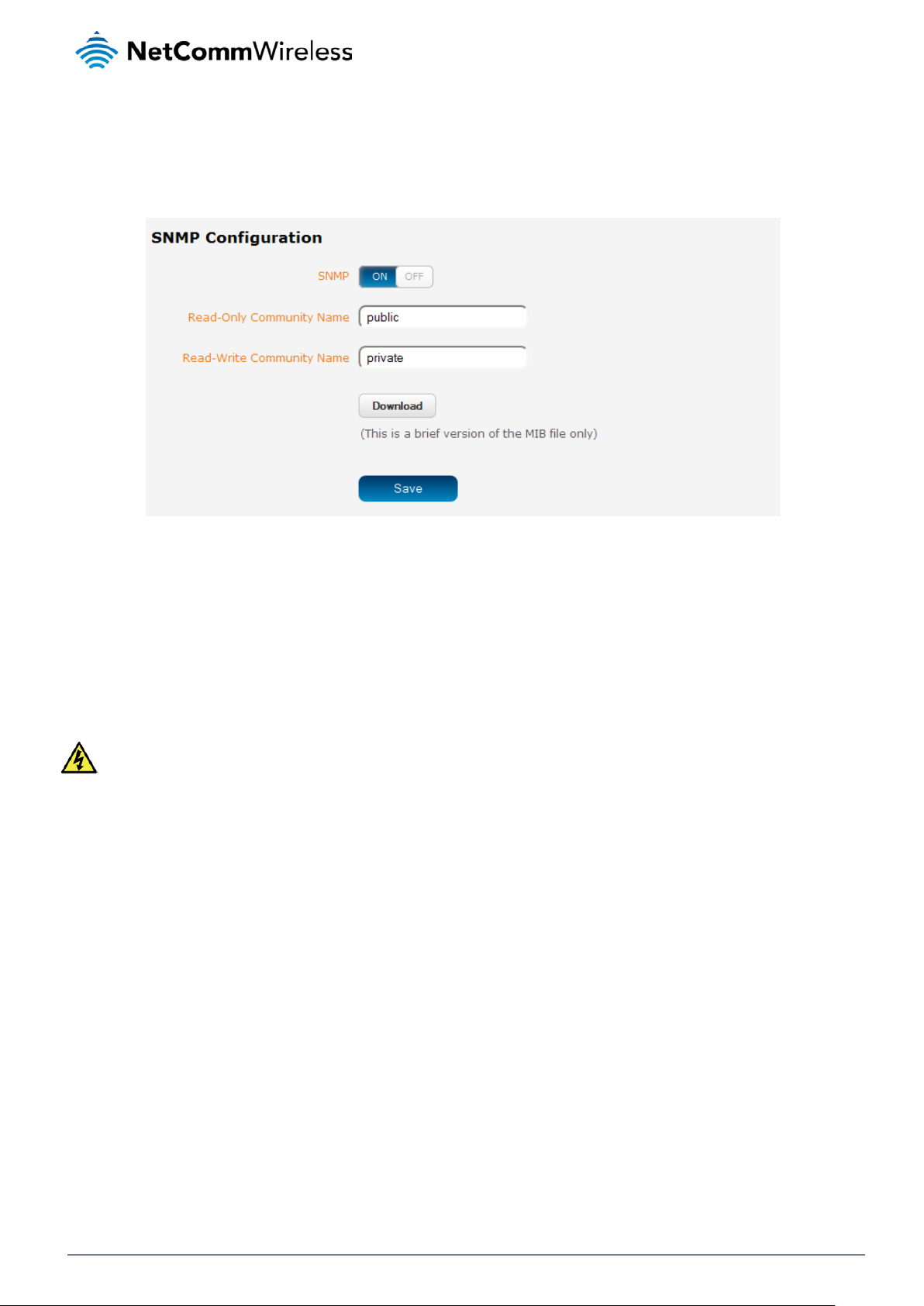
SNMP
SNMP configuration
The SNMP page is used to configure the SNMP features of the router.
Figure 65 - SNMP configuration
SNMP (Simple Network Management Protocol) is used to remotely monitor the router for conditions that may warrant
administrative attention. It can be used to retrieve information from the router such as the signal strength, the system time, the
interface status, etc.
To configure SNMP:
1. Click the SNMP toggle key to switch it to the ON position.
2. Enter Read-Only Community Name and Read-Write Community Name which are used for client authentication.
Community names are used as a type of security to prevent access to reading and/or writing to the routers configuration.
It is recommended that you change the Community names to something other than the default settings when using this
feature.
3. Click the Save button to save any changes to the settings.
The Download button displays the Management information base (MIB) of the router. The MIB displays all the objects of the
router that can have their values set or report their status. The MIB is formatted in the SNMP-related standard RFC1155.
NetComm Wirel ess CDMA M2M Router
60
www.netcommwireless.com
Page 61

SNMP traps
SNMP traps are messages from the router to the Network Management System sent as UDP packets. They are often used to
notify the management system of any significant events such as whether the link is up or down.
Configuring SNMP traps
To configure SNMP traps:
1. In the Trap destination field, enter the IP addr es s to which SNMP data is to be sent.
2. In the Heartbeat interval field, enter the number of seconds between SNMP heartbeats.
3. Use the Trap persistence field to specify the time in seconds that an SNMP trap persists.
4. Use the Trap retransmission time to specify the length of time in seconds between SNMP trap retransmissions.
Figure 66 - SNMP traps
To send a manual SNMP Heartbeat, click the Send heartbeat button.
When you have finished configuring the SNMP traps, click the Save button to save the settings.
www.netcommwireless.com
NetComm Wirel ess CDMA M2M Router
61
Page 62

TR-069
The TR-069 (Technical Report 069) protocol is a technical specification also known as CPE WAN Management Protocol
(CWMP). It is a framework for remote management and auto-configuratio n of end-u ser dev i ces such as cus tom er-premises
equipment (CPE) and Auto Configuration Servers (ACS). It is particularly efficient in applying configuration updates across
networks to multiple CPEs.
TR-069 uses a bi-directional SOAP/HTTP-based protocol based on the application layer protocol and provides several benefits
for the maintenance of a field of CPEs:
Simplifies the initial configuration of a device during installation
Enables easy restoration of service after a factory reset or replacement of a faulty device
Firmware and software version management
Diagnostics and monitoring
Note: You must have your own compatible ACS infrastructure to use TR-069.In order to access and configure the TR069 settings you must be logged into the router as the root user.
TR-069 configuration
To configure TR-069:
1. Click the Enable TR-069 toggle key to switch it to the ON position.
2. In the ACS URL field, enter the Auto Configuration Server’s full domain name or IP address.
3. Use the ACS username field to specify the username for the Auto Configuration Server.
4. In the ACS password and Ve rify ACS password fields, enter the Auto Configuration Server password.
5. In the Connection request username field, enter the username to use for the connection requests.
6. In the Connection request password and Verify password fields, enter the connection request password.
7. The inform message acts as a beacon to inform the ACS of the existence of the router. Click the Enable periodic ACS
informs toggle key to turn on the periodic ACS inform messages.
8. In the Inform period field, enter the number of seconds between the inform messages.
9. Click the Save button to save the settings.
NetComm Wirel ess CDMA M2M Router
62
Figure 67 - TR-069 configuration
www.netcommwireless.com
Page 63

HTTPS
What is HTTP Secure?
HTTP Secure or HTTPS is the use of the HTTP protocol over an SSL/TLS protocol. It is used primarily to protect against
eavesdropping of communication between a web browser and the web site to which it is connected. This is especially important
when you wish to have a secure connection over a public network such as the internet. HTTPS connections are secured
through the use of certificates issued by trusted certificate authorities such as VeriSign. When a web browser makes a
connection attempt to a secured web site, a digital certificate is sent to the browser so that it can verify the authenticity of the
site using a built-in list of trusted certificate authorities.
There are two main differences between how HTTPS and HTTP connections work:
1. HTTPS uses port 443 while HTTP uses port 80 by default.
2. Over an HTTPS connection, all data sent and received is encrypted with SSL while over an HTTP connection, all data
is sent unencrypted.
The encryption is achieved through the use of a pair of public and private keys on both sides of the connection. In cryptography,
a key refers to a numerical value used by an algorithm to alter information (encrypt it), making the information secure and visible
only to those who have the corresponding key to recover (decrypt) the information. The public key is used to encrypt information
and can be distributed freely. The private key is used to decrypt information and must be secret by its owner.
Each CDMA M2M router contains a self-signed digital certificat e which is iden tic al on all CD M A M2M routers. For a greater level
of security, the router also supports generating your own unique key. Additionally, you may use third party software to generate
your own self-signed digital ce rtificate or purchase a signed certificate fro m a trusted certi f ic ate author it y and then upload t hose
certificates to the router.
Generating your own self-signed certificate
To generate your own self-signed certificate:
1. Click the Services item from the top menu bar, then HTTPS from the side menu bar.
2. Enter the certificate details using the appropriate fields. Each field must be completed in order to generate a certificate.
Figure 68 - Generate self signed HTTPS certificate
Note: The Country field must cont ain a code for the desire d coun t ry from the list below.
www.netcommwireless.com
NetComm Wirel ess CDMA M2M Router
63
Page 64

AX
Åland Islands
ER
Eritrea
LS
Lesotho
SA
Saudi Arabia
AE
United Arab Emirates
ET
Ethiopia
LU
Luxembourg
SC
Seychelles
AF
Afghanistan
FI
Finland
LV
Latvia
SE
Sweden
AG
Antigua and Barbuda
AI
Anguilla
FK
Falkland Islands (Malvinas)
MA
Morocco
SH
St. Helena
AL
Albania
FM
Micronesia
MC
Monaco
SI
Slovenia
AM
AN
Netherlands Antilles
FR
France
ME
Montenegro
SK
Slovak Republic
AO
Angola
FX
France, Metropolit an
MG
Madagascar
SL
Sierra Leone
AQ
AR
Argentina
GB
Great Britain (UK)
MK
Macedonia
SN
Senegal
AS
American Samoa
GD
Grenada
ML
Mali
SR
Suriname
AT
Austria
GE
Georgia
MM
Myanmar
ST
Sao Tome and Principe
AU
Australia
GF
French Guiana
MN
Mongolia
SU
USSR (former)
AW
Aruba
GG
Guernsey
MO
Macau
SV
El Salvador
AZ
Azerbaijan
GH
Ghana
MP
Northern Mariana
SZ
Swaziland
BA
Bosnia and
GI
Gibraltar
MQ
Martinique
TC
Turks and Caicos Islands
BD
Bangladesh
GM
Gambia
MS
Montserrat
TF
French Southern Territories
BE
Belgium
GN
Guinea
MT
Malta
TG
Togo
BF
Burkina Faso
GP
Guadeloupe
MU
Mauritius
TH
Thailand
BG
Bulgaria
GQ
Equatorial Guinea
MV
Maldives
TJ
Tajikistan
BH
Bahrain
GR
Greece
MW
Malawi
TK
Tokelau
BI
BJ
Benin
GT
Guatemala
MY
Malaysia
TN
Tunisia
BM
Bermuda
GU
Guam
MZ
Mozambique
TO
Tonga
BN
BO
Bolivia
GY
Guyana
NC
New Caledonia
TR
Turkey
BR
Brazil
HK
Hong Kong
NE
Niger
TT
Trinidad and Tobago
BS
BT
Bhutan
HN
Honduras
NG
Nigeria
TW
Taiwan
BV
Bouvet Island
HR
Croatia (Hrvatska)
NI
Nicaragua
TZ
Tanzania
BW
Botswana
HT
Haiti
NL
Netherlands
UA
Ukraine
BZ
Belize
HU
Hungary
NO
Norway
UG
Uganda
CA
Canada
ID
Indonesia
NP
Nepal
UM
US Minor Outlying Islands
CC
Cocos (Keeling) Islands
IE
Ireland
NR
Nauru
US
United States
CF
Central African Republic
IL
Israel
NT
Neutral Zone
UY
Uruguay
CH
Switzerland
IM
Isle of Man
NU
Niue
UZ
Uzbekistan
CI
Cote D'Ivoire (Ivory
IN
India
NZ
New Zealand
VA
Vatican City State (Holy See)
CK
Cook Islands
IO
British Indian Ocean
OM
Oman
VC
Saint Vincent and the
CL
CM
Cameroon
IT
Italy
PE
Peru
VG
Virgin Islands (British)
CN
China
JE
Jersey
PF
French Polynesia
VI
Virgin Islands (U.S.)
CR
Costa Rica
JO
Jordan
PH
Philippines
VU
Vanuatu
CS
Czechoslovakia
JP
Japan
PK
Pakistan
WF
Wallis and Futuna Islands
CV
CX
Christmas Island
KG
Kyrgyzstan
PM
St. Pierre and
YE
Yemen
CY
Cyprus
KH
Cambodia
PN
Pitcairn
YT
Mayotte
CZ
Czech Republic
KI
Kiribati
PR
Puerto Rico
ZA
South Africa
DE
Germany
KM
Comoros
PS
Palestinian Territory
ZM
Zambia
DJ
Djibouti
KN
Saint Kitts and Nevis
PT
Portugal
COM
US Commercial
DK
Denmark
KR
Korea (South)
PW
Palau
EDU
US Educational
DM
Dominica
KW
Kuwait
PY
Paraguay
GOV
US Government
DO
Dominican Republic
KY
Cayman Islands
QA
Qatar
INT
International
DZ
Algeria
KZ
Kazakhstan
RE
Reunion
MIL
US Military
EC
Ecuador
LA
Laos
RO
Romania
NET
Network
EG
Egypt
LI
Liechtenstein
RU
Russian Federation
ARPA
Old style Arpanet
EH
Western Sahara
LK
Sri Lanka
RW
Rwanda
CODE COUNTRY CODE COUNTRY CODE COUNTRY CODE COUNTRY
AD Andorra
Armenia FO Faroe Isla nds MD Moldova SJ Svalbard and Jan Mayen
Antarctica GA Gabon MH Marshall Islands SM San Marino
BB
Barbados GL Greenland MR Mauritania TD Chad
Burundi GS S. Georgia and S. Sandwich
ES Spain LT Lithuania SB Solomon Islands
FJ Fiji LY Libya SG Singapore
MX Mexico TM Turkmenistan
CO
Brunei Darussalam GW Guinea-Bissau NA Namibia TP East Timor
Bahamas HM Heard and McDonald Islands NF Norfolk Island TV Tuvalu
Chile IS Iceland PA Panama VE Venezuela
Colombia JM Jamaica PG Papua New Guinea VN Viet Nam
Cape Verde KE Kenya PL Poland WS Samoa
EE
Estonia LC Saint Lucia RS
NetComm Wirel ess CDMA M2M Router
64
Serbia
ORG Non-Profit Organization
www.netcommwireless.com
Page 65

3. When you have entered all the required details, press the Generate button. The certificate takes several minutes to
generate. When the certificate has been generated, you are informed that it has been successfully generated and
installed. The web server on the router restarts and you are logged out of the router. Click OK to be taken back to the
login screen.
Figure 69 - New certificate successfully generated message
www.netcommwireless.com
NetComm Wirel ess CDMA M2M Router
65
Page 66

SSH Server Configuration
Secure Shell (SSH) is UNIX-based command interface and network protocol u sed to gain secure access to a remote computer,
execute commands on a remote machine or to transfer files between machines. It was designed as a replacement for Telnet
and other insecure remote shell protocols which send information, including passwords, as plain text.
SSH uses RSA public key cryptography for both connection and authentication. There are several ways of using SSH:
Use automatically generated public-private key pair s to encry pt the netw ork conn ect ion and then use pas sw or d
authentication to log on.
Use a manually generated public-private key pair to perform the authentication and allow users or programs to log
in without using a password.
Figure 70 - SSH Server Configuration
To configure SSH:
1. Select the types of authentication you want to use by clicking the Enable password authentication and Enable key
authentication toggle keys on or off.
2. Click the Save button.
3.
NetComm Wirel ess CDMA M2M Router
66
www.netcommwireless.com
Page 67

SMS Diagnostics and Commands
SMS messaging
The CDMA M2M router offers an advanced SMS feature set, including sending messages, receiving messages, redirecting
incoming messages to another destination, as well as supporting remote commands and diagnostics messages.
Some of the functions supported include:
Ability to send a text message via a CDMA network and store it in per man ent stora ge.
Ability to receive a text message via a CDMA network and store it in permanent storage.
Ability to forward incoming text messages via a CDMA network to another remote destination which may be a
TCP/UDP server or other mobile devices.
Ability to receive run-time variables from the device (e.g. uptime) on request via SMS
Ability to change live configuration on the device (e.g. network username) via SMS.
Ability to execute supported commands (e.g. reboot) via SMS
Ability to trigger the CDMA M2M router to download and install a firmware upgrade
Ability to trigger the CDMA M2M router to download and apply a configuration file
To access the SMS messaging functions of the CDMA M2M router, click on the Services menu item from the top menu bar, and
then select one of the options under the SMS messaging section on the left hand menu.
Setup
The Setup page provides the options to enable or disable the SMS messaging functionality and SMS forwarding functionalities
of the router. SMS messaging is enabled by default.
www.netcommwireless.com
Figure 71 - General SMS Configuration
NetComm Wirel ess CDMA M2M Router
67
Page 68

OPTION DEFINITION
General SMS configuration
SMS messaging Toggles the SMS functionality of the router on and off.
Messages per page (10-50) The number of SMS messages to display per page. Must be a value between 10 and 50.
Encoding scheme
SMSC address
Routing Option
SMS forwarding configuration
Forwarding Toggles the SMS forwarding function of the router on and off.
Redirect to mobile Enter a mobile number as the destination for forwarded SMS messages.
TCP address
TCP port The TCP port on which to connect to the remote destination.
UDP address
UDP port The UDP port on which to connect to the remote destination.
The encoding method used for outbound SMS messages. GSM 7-bit mode permits up to
160 characters per message but drops to 50 characters if the message includes special
characters. UCS-2 mode allows the sending of Unicode characters and permits a message
to be up to 50 characters in length.
The short message service centre (SMSC) address is the number of your mobile broadband
SMS provider. The SMSC address is used when sending text messages and is stored on
the SIM card. If the SMSC address field is blank, the router will not be able to send any SMS
messages.
Allows you to configure the method used to route SMS messages.
Packet-switched: Uses the switched IP packet network to deliver messages. Messa ges ar e
broken up into packets and transmitted through the network independently, then reassembled when they reach the destination. In packet switched networks, network links are
shared by packets from multiple competing communication sessions. Packet switching
generally results in a lower quality of service compared with circuit switched networks
because the packets may take different routes to the destination and cause delay in their reassembly.
Circuit-switched: Creates a route with reserved bandwidth from the source to the destination,
emulating a physical connection with an electrical circuit. Data transmitted in a circuit
switched network is delivered in order and has a constant bit delay meaning the service is
predictable and reliable.
Packet-switched preferred: Attempts to use the packet-switched network for SMS delivery
but fails over to the circuit-switched network if messages are undeliverable.
Circuit-switched preferred: Attempts to use the circuit-switched network for SMS delivery but
fails over to the packet-switched network if messages are undeliverable.
Enter an IP address or domain name as the destination for forwarded SMS messages using
TCP.
Enter an IP address or domain name as the destination for forwarded SMS messages using
UDP.
Table 15 - SMS Setup Settings
NetComm Wirel ess CDMA M2M Router
68
www.netcommwireless.com
Page 69

SMS forwarding config ur ati on
Incoming text messages can be redirected to another mobile device and/or a TCP/UDP message server.
Redirect to mobile
You can forward incoming text messages to a different destination number. This destination number can be another mobile
phone or a 3G router phone number.
For Example:
If someone sends a text message and Redirect to mobile is set to “+61412345678”, the text message is stored on the router
and forwarded to “+61412345678” at the same time.
To disable redirection to a mobile, clear the Red i rect to mo bil e field and click the Save button.
Redirect to TCP / UDP address
You can also forward incoming text messages to a TCP/UDP based destination. The TCP or UDP server can be any kind of
public or private server if the server accepts incoming text-based me ssa ge.
The TCP/UDP address can be an IP address or domain name. The port number range is from 1 to 65535. Please refer to your
TCP/UDP based SMS server configuration for which port to use.
For Example:
If someone sends a text message and TCP address is set to “192.168.20.3” and TCP port is set to “2002”, this text message is
stored in the router and forwarded to “192.168.20.3” on port “2002” at the same time.
To disable redirection to a TCP or UDP address, clear the TCP address and UDP address fields and click the Save button.
www.netcommwireless.com
NetComm Wirel ess CDMA M2M Router
69
Page 70

New message
The New message page can be used to send SMS text messages to a single or multiple recipients.
A new SMS message can be sent to a maximum of 100 recipients at the same time. After sending the message, the result is
displayed next to the destination number as “Success” or “Failure” if the message failed to send. By default, only one destination
number field is displayed. Additional destination numbers may be added one at a time after entering a valid number for the
current destination number field. To add a destination number, click the button and to remove the last destination in the list,
click the button.
Figure 72 - SMS - New Message
Destination numbers should begin with the “+” symbol followed by the country calling code. To send a message to a destinati on
number, enter the “+” symbol followed by the country calling code and then the destination number.
For example:
To send a message to the mobile destination number 0412345678 in Australia (country calling code 61), enter
“+61412345678”.
After entering the required recipient numbers, type your SMS message in the New message field. As you type your message, a
counter shows how many characters you have entered out of the total number available for your chosen encoding scheme.
When you have finished typing your message and you are ready to send it, click the Send button.
NetComm Wirel ess CDMA M2M Router
70
www.netcommwireless.com
Page 71

Inbox / Outbox
The Inbox displays all received messages that are stored on the router while the Outbox displays all sent messages.
Figure 73 - SMS Inbox
Figure 74 - SMS Outbox
ICON DESCRIPTION
Forward button. Click this button to open a new message window where you can
forward the corresponding message to another recipient.
Reply button. Click this button to open a new message window where you can reply
to the sender.
Add to White list. Click this button to add the sender’s mobile number to the white list
on the router.
Delete button. Click this button to delete the corresponding message.
Refresh button. Click this button to refresh the inbox or outbox to see new messages.
Table 16 - Inbox/Outbox icons
www.netcommwireless.com
NetComm Wirel ess CDMA M2M Router
71
Page 72

Diagnostics
The Diagnostics page is used to configure the SMS diagnostics and command execution configuration. This enables you to
change the configuration, perform functions remotely and check on the status of the router via SMS commands.
SMS diagnostics and com ma nd execution configurat ion
Figure 75 - SMS diagnostics and command execution configuration
The options on this page are described below.
Enable remote diagnostics and command execution
Enables or disables the remote diagnostics feature. If this setting is enabled all incoming text messages are parsed and tested
for remote diagnostics commands.
If remote diagnostics commands are found, the router executes those commands. This feature is enabled by default. All remote
diagnostic commands that are received are stored in the Inbox.
Note: It is possible to adjust settings and prevent your router from functioning correctly using remote diagnostics. If this
occurs, you will need to perform a factory reset in order to restore normal operation.
We highly recommended that you use the white li st and a password when utilising this feature to prevent unauthorise d
access. See the White list
description for more information.
Only accept authenticated SMS messages
Enables or disables checking the sender’s phone number against the allowed sender white list for incoming diagnostics and
command execution SMS messages.
If authentication is enabled, the router will check if the sender’s number exists in the white list. If it exists, the router then checks
the password (if configured) in the incoming message against the password in the white list for the corresponding sending
number. If they match, the diagnostic or command is executed.
If the number does not exist in the white list or the password does not match, the router does not execute the incoming
diagnostic or command in the SMS message.
This is enabled by default and it is strongly advised that you leave this feature enabled to maintain security.
NetComm Wirel ess CDMA M2M Router
72
www.netcommwireless.com
Page 73

Send Set command acknowledgment replies
The CDMA M2M router will automatically reply to certain types of commands received, such as get commands, or execute
commands. However replies from the CDMA M2M router are optional with set commands and the Wakeup command. This
option Enables or disables sending an acknowledgment message after execution of a set command or SMS Wakeup command.
If disabled, the router does not send any acknowledgement after execution of a set command or SMS Wakeup command. All
acknowledgment replies are stored in the Outbox after they have been sent.
This can be useful to determine if a command was received and executed by the router. This option is disabled by default.
Send acknowledgment replies to
This option allows you to specify where to send acknowledgment messages after the execution of a set, or exec command.
If a fixed number is selected, the acknowledgement message will be sent to the number defined in the Fixed number to send
replies to field. If the sender’s number is selected, the acknowledgement message will be sent to the number that the SM S
diagnostic or command message originated from. The default setting is to use the sender’s number.
Fixed number to send replies to
This field defines the destination number to which acknowledgement messages are sent after the execution of a set, or exec
command.
Send command error replies
Enables or disables the sending of an error message resulting from the execution of a get, set, or exec command. All error
replies are stored in the Outbox after they have been sent.
If disabled, the router does not send any error notifications after the execution of a get, set, or exec command. This function is
enabled by default.
Send error replies to
This option allows you to specify where to send error messages from the execution of a get, set, or exec command.
If a fixed number is selected, any error messages will be sent to the number defined in the fixed number to send error
replies to field. If the sender’s number is selected, any error messages will be sent to the number that the SMS diagnostic or
command message originated from. The default setting is to use the sender’s number.
Fixed number to send error replies to
This field defines the destination number to which error messages are sent after the execution of a get, set, or exec command.
Send a maximum of ___ replies per ___
You can set the maximum number of acknowledgement and error messages sent when an SMS diagnostic or command is
executed. The maximum limit can be set per hour, day, week or month. The router will send a maximum of 100 replies by
default.
The number of messages sent is shown below the options. The total trans mit ted me ssa ge c ount re set s after a reboot or at the
beginning of the time frame specified.
www.netcommwireless.com
NetComm Wirel ess CDMA M2M Router
73
Page 74

White list for diagnostic or execution SMS
The white list is a list of mobile numbers that you can create which are considered “friendly” to the router. If Only accept
authenticated SMS messages is enabled in the diagnostics section, the router will compare the mobile number of all incoming
diagnostic and command messages against this white list to determine whether the diagnostic or command should be executed.
You may optionally configure a password for each number to give an additional level of security. When a password is specified
for a number, the SMS diagnostic or command message is parsed for the password and will only be executed if the number and
password match.
Figure 76 - White list for diagnostic or execution SMS
A maximum of 20 numbers can be stored on the router in the white list.
One blank entry is shown by default and you can add a number by clicking the “+Add” button. The White List numbers and
passwords can be cleared by pressing the button to the right of each entry. To add a number to the white list, enter it in the
Destination number field and optionally define a password in the Password field. When you have finished adding numbers
click the Save button to save the entries.
NetComm Wirel ess CDMA M2M Router
74
www.netcommwireless.com
Page 75

Sending an SMS diagnostic command
Follow the steps below to configure the router to optionally accept SMS diagnostic commands only from authenticated senders
and learn how to send SMS diagnostic commands to the router.
1. Navigate to the Services > SMS messaging > Diagnostics page
2. Confirm that the Enable remote diagnostics and command execution toggle key is set to the ON position. If it is set
to OFF click the toggle key to switch it to the ON position.
3. If you wish to have the router only accept commands from authenticated senders, ensure that Only accept
authenticated SMS messages is set to the ON position. This is the default setting. In the White list for diagnostic or
execution SMS section, click the +Add button and enter the sender’s number in internation al for mat into the
Destination number field that appears. If you wish to also configure a password, enter the password in the Password
field corresponding to the destination number.
4. If you would prefer to accept SMS diagnostic commands from any sender, set the Only accept authenticated SMS
messages toggle key to the OFF position.
Note: An alternative method of adding a number to the white list is to send an SMS message to the router, navigate to Services
> SMS messaging > Inbox and then click the button next to the message which corresponds to the sender’s
number.
5. Click the Save button.
Types of SMS diagnostic commands
There are three types of commands that can be sent; execute, get and set. The basic syntax is as follows:
execute COMMAND
get VARIABLE
set VARIABLE=VALUE
If authentication is enabled, each command must be preceded by the password:
PASSWORD execute COMMAND
PASSWORD get VARIABLE
PASSWORD set VARIABLE=VALUE
The following are some examples of SMS diagnostic commands:
password6657 execute reboot
get rssi
set apn1=testAPNvalue
SMS Acknowledgment replies
The router automatically replies to get commands with a value and execute commands with either a success or error response.
Set commands will only be responded to if the Send Set co mmand acknowledgement replies toggle key is set to ON. If the
Send command error replies toggle key is set to ON, the router will send a reply if the command is correct but a variable or
value is incorrect, for example, due to misspelling.
www.netcommwireless.com
NetComm Wirel ess CDMA M2M Router
75
Page 76

SMS Command format
Generic Format for reading variables:
get VARIABLE
PASSWORD get VARIABLE
Generic Format for writing to variables:
set VARIABLE=VALUE
PASSWORD set VARIABLE=VALUE
Generic Format for executing a command:
Execute COMMAND
PASSWORD execute COMMAND
Replies
Upon receipt of a succes sfu lly format t ed, aut henticated (if required) command, the gateway will reply to the SMS in the following
format:
TYPE SMS CONTE NTS NOTES
get command “VARIABLE=VALUE”
Only sent if the
set command “Successfully set VARIABLE to VALUE”
execute command
Where “VARIABLE” is the name of the value to be read
Where “VARIABLE (x)” is the name of another value to be read
Where “VALUE” is the content to be written to the “VARIABLE”
Where “COMMAND” is a supported command to be executed by the device (e.g. reboot)
Where “PASSWORD” is the password (if configured) for the corresponding sender number specified in the White List
Multiple commands can be sent in the same message, if separated by a semicolon.
For Example:
get VARIABLE1; get VARIABLE2; get VARIABLE3
PASSWORD get VARIABLE1; get VARIABLE2
set VARIABLE=VALUE1 ; set VARIABLE2=VALUE2
PASSWORD set VARIABLE1=VALUE1; set VARIABLE2=VALUE2; set VARIABLE3=VALUE3
If required, values can also be bound by an apostrophe, double apostrophe or back tick.
For Example:
“set VARIABLE=’VALUE’”
“set VARIABLE=”VALUE””
“set VARIABLE=`VALUE`”
“get VARIABLE”
“Successfully executed comm and
COMMAND”
Table 17 - SMS Diagnostic Command Syntax
acknowledgment message
function is enabled
NetComm Wirel ess CDMA M2M Router
76
www.netcommwireless.com
Page 77
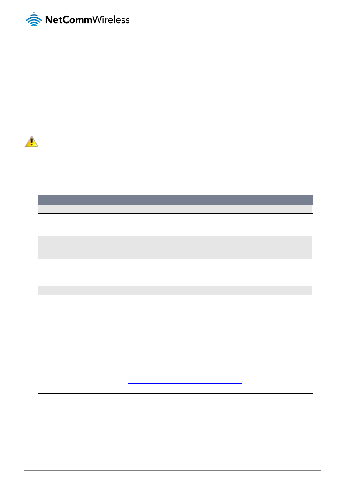
A password (if required), only needs to be specified once per SMS, but can be prefixed to each command if desired.
“PASSWORD get Variable1”; “get VARIABLE2”
“PASSWORD set VARIABLE1=VALUE1”; “set VARIABLE2=VALUE2”
If the command sent includes the “reboot” command and has already passed the white list password check, the device keeps
this password and executes the remaining command line after the reboot with this same password.
For Example:
“PASSWORD execute reboot; getVariable1”; “get VARABLE2”
“PASSWORD execute reboot; PASSWORD get Variable1”; “get VARABLE2”
Note: Commands, variables and values are case sensitive.
List of valid commands
A list of valid commands which can be used in conjunction with the execute command are listed below:
“pdpcycle”, “pdpdown” and “pdpup” commands can have a profile number suffix ‘x’ added. Without the suffix specified, the
command operates against the default profile configured on the profile list page of the Web-UI.
# COMMAND NAME DESCRIPTION
1 reboot Immediately performs a soft reboot.
Disconnects (if connected) and reconnects the 3G connection. If a profile number is selected in the
2 pdpcycle or pdpcyclex
3 pdpdown or pdpdownx
4 pdpup or pdpupx
5 factorydefaults Performs a factory reset on the router.
6 download
command, try to disconnect/reconnect the specified profile in case the profile is active. If no profile
number is selected, try to disconnect/reconnect the current active profile. Reports an error if no
profile number is selected and there is no currently activated profile.
Disconnects the PDP. If a profile number is selected in the command, the router tries to di sc onn ec t
the specified profile in case the profile is active. If no profile number is selected, try to disconnect the
current active profile. Reports an error if no profile number is selected and there is no currently
activated profile.
Reconnects the PDP. If a profile number is selected in the command, the router tries to con nec t wit h
the specified profile. If no profile number is selected, the router tries to connect to the last active
profile. The gateway will check the currently activated profile and disconnect this profile before
executing the command. The router reports an error if no profile number is selected and there is no
stored last active profile number.
Performs a download and install of a Firmware Upgrade (.cdi), Config File (.tar.gz) or a help
document (.pdf) file.
If the file is a firmware image as in the case of a .cdi file, the router will apply the recovery image first
and then the main firmware image. The download location is specified immediately after the
command and may be from an HTTP or FTP source URL.
If the file is a .tar.gz file, the router will apply the file as a configuration file update for the device and
reboot afterwards.
If the file is a .pdf, the router will assume this is a user guide document and save it to the router and
make the file available for viewing via the help menu on the Web-UI.
Note: If your download URL includes any space characters, please encode these prior to
transmission according to RFC1738, for example:
ftp://username:password@serveraddress/directory%20with%20spaces/filename.cdi
Note: Authenticated FTP addresses may be used following the format as defined in RFC1738, for
example:
ftp://username:password@serveraddress/directory/filename.cdi
Table 18 - List of Valid SMS diagnostic commands
www.netcommwireless.com
NetComm Wirel ess CDMA M2M Router
77
Page 78

The following table lists valid variables where “x” is a profile number (1-6). If no profile is specified, variables are read from or
written to for the current acti v e profile. If a profile is specified, variables are read from or written to for the specified profile
number (‘x’).
# RDB VARIABLE NAME
link.profile.x.enable
link.profile.x.apn
link.profile.x.user
0
link.profile.x.pass
link.profile.x.auth_type
link.profile.x.iplocal
link.profile.x.status
1 link.profile.x.apn apn or apnx RW APN internet
link.profile.x.user
2
link.profile.x.pass
3
4 link.profile.x.auth_type authtype or authtypex RW
link.profile.x.iplocal
5
6 wwan.0.radio.information.signal_strength rssi R 3G signal strength 65 dBm
wwan.0.imei
7
statistics.usage_current
8
statistics.usage_current
9
10 /proc/uptime deviceuptime R Device up time 1 days 02:30:12
wwan.0.system_network_status.current_b
11
and
SMS VARIABLE
NAME
profile
or
profilex
username or
usernamex
password or passwordx RW 3G password Guest, could also return “null”
wanip or wanipx R WAN IP address 202.44.185.111
imei R IME I numb er 359102128941027512
usage R
wanuptime R
band R
Table 19 - List of SMS diagnostics variables
READ/
WRITE
RW Profile
RW 3G username Guest, could also return “null”
DESCRIPTION EXAMPLE VALUE
Read:
(profile no,apn,user,pass,auth,iplocal,status)
1,internet,username,password,
chap,202.44.185.111,up
Write:
(apn, user, pass,auth)
internet,username,password
3G Authentication
type
3G data usage of
current session
Up time of current 3G
session
Current 3G
frequency
”pap” or”chap”
“Rx 500 bytes, Tx 1024 bytes, Tot al 15 24
bytes” or “Rx 0 byte, Tx 0 byte, Total 0 byte”
when wwan down
1 days 02:30:12 or 0 days 00:00:0 0 wh en
wwan down
WCDMA 850
Network scan and manual network selecti on b y SMS
Performing a network scan
The get plmnscan SMS command enables you to perform a scan of the cellular networks available at the time of the scan.
It returns the following semi-colon separated information for each network in range:
MCC
MNC
Network Type (3G, 2G)
Provider's Name
Operator Status (available, forbidden, current)
The following is an example of a response from the get plmnscan SMS command:
plmnscan:505,3,7,vodafone AU,4;505,3,1,vodafone AU,1;505,2,7,YES OPTUS,1;505,2,1,YES OPTUS,1;505,1,1,Telstra
Mobile,1;505,1,7,Telstra Mobile,1
NetComm Wirel ess CDMA M2M Router
78
www.netcommwireless.com
Page 79

NETWORK
TYPE
7 Indicates a 3G network
1 Indicates a 2G network
Table 20 - Network types returned by get plmnscan SMS command
DESCRIPTION
OPERATOR
STATUS
1 Indicates an availa bl e op era to r whic h m a y be selected.
2
4 Indicates the currently selected operator.
Indicates a forbidden operator which may not be selected (applies only to generic SIM
cards).
Table 21 - Operator status codes returned by get plmnscan SMS command
DESCRIPTION
Notes about the networ k connecti on status when using the get plmnscan command:
If the connection status is Up and connection mode is Always on, the get plmnscan SMS will cause the connect ion to
disconnect, perform the scan, send the result through SMS and then bring the connection back up again. If the connection
status is Down, the router will perform the PLMN scan, send the result and keep the connection status down.
If the connection status is Waiting and connection mode is Connect on demand, the get plmnscan SMS will change the
connection status to Down, perform the scan, send the result through SMS and then restore the connection status to the
Waiting state.
If the connection status is Up and connection mode is Connect on demand, the get plmnscan SMS will cause the connection
to disconnect, perform the scan, send the result through SMS, and then restore the connection status to the Waiting state
unless there is a traffic which triggers a connection in which case the connection status will be set to Up.
Setting the router to connect to a network
The router can be instructed by SMS to connect to one of the networks returned by the get plmnscan command. The set
forceplmn command forces the router to connect to a specified operator network (if available) while the get forceplmn
command retrieves the currently configured network on the router.
Command format:
set forceplmn=0|MCC,MNC| MCC,MNC,Network Type
For example:
set forceplmn=0
Sets the selection of operator and network type to automatic mode.
set forceplmn=505,3
Sets the operator to a manua l selecti on mad e by the user where “505” is the Mobile Country Code for Australia and “3” is the
Mobile Network Code for Vodafone. As no network type (i.e. 3G or 2G) is specified, it is selected automatically.
set forceplmn=505,3,7
Sets the operator and network type to a manual selection made by the user where “505” is the Mobile Country Code for
Australia, “3” is the Mobile Network Code for Vodafone and “7” is the 3G network type.
www.netcommwireless.com
NetComm Wirel ess CDMA M2M Router
79
Page 80

Notes about the set forceplmn command:
If the manual selection fails, the device will fall back to the previous ‘good’ network.
When enabled, the SMS acknowledgement reply reflects the success or failure of the manual selection with respect to the
set
command and includes the final MNC/MCC that was configured.
Confirming the currently configured operator and network type
You can retrieve the currently configured operator and network type using the get forceplmn command.
The get forceplmn comma nd retur n s the operator and network type selection mode (Automati c/Manual), in addition to the MCC
and MNC values, for example:
Automatic,505,3
This response indicates that the operator/network selection mode is Automatic, and the network used is Vodafone AU.
SMS diagnostics examples
The examples below demonstrate various combinations of supported commands. This is not an exhaustive list and serves as an
example of possibilities only.
DESCRIPTION AUTHENTICATION INPUT EXAMPLE
set apn1=internet
set apn2=”access”
PASSWORD set apn1=internet
PASSWORD set apn2=access
Send SMS to change APN
Send SMS to change the 3G
username
Send SMS to change the 3G
password
Send SMS to change the 3G
authentication
Send SMS to reboot
Send SMS to check the WAN IP
address
Send SMS to check the 3G signal
strength
Send SMS to check the IMEI
number
Send SMS to check the current
band
Send SMS to Disconnect (if
connected) and reconnect the 3G
connection
Send SMS to disconnect the 3G
connection
Send SMS to connect the 3G
connection
Send multiple get command
Send multiple set command
Send SMS to reset to factory
Not required
Required
Not required set username=’NetComm’
Required PASSWORD set username= ”NetComm”
Not required set password= `NetComm`
Required PASSWORD set password= `NetComm`
Not required set authtype= ‘pap’
Required PASSWORD set authtype = pap
Not required execute reboot
Required PASSWORD execute reboot
Not required get wanip
Required PASSWORD get wanip
Not required get rssi
Required PASSWORD get rssi
Not required get imei
Required PASSWORD get imei
Not required get band
Required PASSWORD get band
Not required execute pdpcycle
Required PASSWORD execute “pdpcycle1”
Not required execute pdpdown1
Required PASSWORD execute “pdpdown1”
Not required execute pdpup
Required PASSWORD execute pdpup1
Not required get wanip; get rssi
Required PASSWORD get wanip; get rssi
Not required set apn1=”3netaccecss”; set password1=’NetComm’
Required PASSWORD set APN=”3netaccecss”; set password=NetComm
Not required execute factorydefaults
NetComm Wirel ess CDMA M2M Router
80
www.netcommwireless.com
Page 81

default settings
Send SMS to retrieve status of
router
Send SMS to retrieve the history of
the session, including start time,
end time and total data usage
Send SMS to configure the router
to send syslog to a remote syslog
server
Send SMS to wake up the router,
turn on the default gateway and
trigger the ‘connect on demand’
profile if in waiting state.
Send SMS to retrieve MCC, MNC,
network type, provider’ s nam e an d
operator status
Send SMS to retrieve current
network type selection mode, MNC
and MCC values.
Send SMS to force connection to a
specific operator and network type
Send SMS to perform firmware
upgrade when firmware is located
on HTTP server
Send SMS to perform firmware
upgrade when firmware is located
on FTP server
Send SMS to turn off PPPoE
Send SMS to turn on PPPoE and
set APN and service name
Send SMS to retrieve the PPPoE
status, currently configured APN
and service name
Send SMS to set the default data
connection profile
Send SMS to retrieve the currently
configured default data connection
profile
Send SMS to set the LED mode
timeout to 10 minutes
Send SMS to retrieve the current
LED mode
Required PASSWORD execute factorydefaults
Not required get status
Required PASSWORD get status
Not required get sessionhistory
Required PASSWORD get sessionhistory
Not required set syslogserver
Required PASSWORD set syslogserver
Not required A zero byte class 1 flash SMS
Not required get plmnscan
Required PASSWORD get plmnscan
Not required get forceplmn
Required PASSWORD get forceplmn
Not required set forceplmn=505,1,7
Required PASSWORD set forceplmn=505,1,7
Not required
Required
Not required
Required
Not required set pppoe=0
Required PASSWORD set pppoe=0
Not required set pppoe=1,internet, Vodafone
Required PASSWORD set pppoe=1,internet, Vodafone
Not required get pppoe
Required PASSWORD get pppoe
Not required set defaultprofile=1
Required PASSWORD set defaultprofile=1
Not required get defaultprofile
Required PASSWORD get defaultprofile
Not required set ledmode=10
Required PASSWORD set ledmode=10
Not required get ledmode
Required PASSWORD get ledmode
execute download http://download.com:8080/firmware_image.cdi
execute download http://download.com:8080/firmware_image_r.cdi
PASSWORD execute download
http://download.com:8080/firmware_image.cdi
PASSWORD execute download
http://download.com:8080/firmware_image_r.cdi
execute download
ftp://username:password@download.com:8080/firmware_image.cdi
execute download ftp://username:password@
download.com:8080/firmware_image_r.cdi
PASSWORD execute download ftp://username:password@
download.com:8080/firmware_image.cdi
PASSWORD execute download ftp://username:password@
download.com:8080/firmware_image_r.cdi
Table 22 - SMS diagnostics example commands
www.netcommwireless.com
NetComm Wirel ess CDMA M2M Router
81
Page 82

System
Log
The Log pages are used to display or download the System log and IPSec logs on the router.
System log
The System Log enables you to troubleshoot any issues you may be experiencing with your CDMA M2M router.
Log data is stored in RAM and therefore, when the unit loses power or is rebooted it will lose any log information stored in RAM.
To ensure that log information is accessible between reboots of the router there are two options:
1. Enable the Log to non-volatile memory option
2. Use a remote syslog server
Enable log to non-volatile memory
When the router is configured to log to non-volatile memory, the log data is stored in flash memory, making it accessible after a
reboot of the router. Up to 512kb of log data will be stored before it is overwritten by new log data. Flash memory has a finite
number of program-erase operations that it may perform to the blocks of memory. While this number of program-erase
operations is quite large, we recommend that you do not enable this option for anything other than debugging to avoid
excessive wear on the memory.
Use a remote syslog server
The router can be configured to output log data to a remote syslog server. This is an application running on a remote computer
which accepts and displays the log data. Most syslog servers can also save the log data to a file on the computer on which it is
running allowing you to ensure that no log data is lost between reboots.
To configure the CDMA M2M Router to output log data to a remote syslog server:
1. Click on the System menu from the top menu bar. The System log item is displayed.
2. Click on the Administration settings item from the menu on the left.
3. Under the Remote syslog server section, enter the IP address or hostname of the syslog server in the IP / Hostname
[:PORT] field. You can also specify the port number after the IP or hostname by entering a semi-colon and then the
port number e.g. 192.168.1.102:514. If you do not specify a port number, the router will use the default UDP port 514.
4. Click the Save button to save the configuration.
Log file
The Log to non-volatile memory option, when enabled, stores the log data in a file in flash memory making it available after a
reboot.
Use the Display level drop-down list to select a message level to be displayed. The message levels are described in the table
below.
To download the System log for offline viewing, right-click the Download button and choose Save as.. to save the file. To clear
the System log, click the Clear button. The downloaded log file is in Linux text format with carriage return (CR) only at the end of
a line, therefore in order to be displayed correctly with new lines shown, it is recommended to use a text file viewer which
displays this format correctly (e.g. Notepad++).
NetComm Wirel ess CDMA M2M Router
82
www.netcommwireless.com
Page 83

ITEM DEFINITION
All Display all system log messages.
Debug Show extended system log messages with full debugging level details.
Info Show informational messages only.
Notice Show normal system logging information.
Warning Show warning messages only.
Error Show error condition messages only.
www.netcommwireless.com
Figure 77 - System log
Table 23 - System log detail levels
NetComm Wirel ess CDMA M2M Router
83
Page 84

IPSec log
The IPSec log section provides the ability for you to download the log for the IPSec VPN function. This can assist in
troubleshooting any problems you may have with the IPSec VPN.
Use the Log level drop down list to specify the type of detail you want to capture in the log and then click the Save button.
When you change the logging level, any active IPSec VPN tunnels will be disconnected as a change in logging level requires
the IPSec service to be restarted.
To download the IPSec log, click the IPSec log download button and you will be prompted to save the file.
Figure 78 - IPSec log
NetComm Wirel ess CDMA M2M Router
84
www.netcommwireless.com
Page 85

System configuration
Settings backup and restore
The settings backup and restore page is used to backup or restore the router’s configuration or to reset it to factory defaults. In
order to view the settings page you must be logged into the web user interface as root using the passwor d admin. The backup
and restore functions can be used to easily configure a large number of CDMA M2M router by configuring one router with your
desired settings, backing them up to a file and then restoring that file to multiple CDMA M2M routers.
Figure 79 – Settings backup and restore
Back up your router’s configuration
Log in to the web configuration interface, click on the System menu and select Settings backup and restore.
If you want to password protect your backup configuration files, enter your password in the fields under Save a copy of current
settings and click on Save. If you don’t want to password protect your files, just click on Save. The router will then prompt you
to select a location to save the settings file.
Note: The following conditions apply:-
It is NOT possible to edit the contents of the file downloaded; if you modify the contents of the configuration file in any
•
way you will not be able to restore it later.
You may change the name of the file if you wish but the filename extension must remain as “.cfg”
•
Restore your backup configuration
1. In the web configuration interface click on the System System menu and select Settings backup and restore.
2. From the Restore saved settings section, click on Browse and select the backup configuration file on your computer.
3. Click Restore to copy the settings to the new CDMA M2M router. The router will apply these settings and inform you it
will reboot - click on OK.
Restoring the router’s factory default configuration
Click the Restore defaults button to restore the factory default configuration. The router asks you to confirm that you wish to
restore factory default settings. If you wish to continue with the restoring of factory defaults, click OK.
Note: All current settings on the router will be lost when performing a restore of factory default settings. The device IP
address will change to 192.168.1.1 and the defa ult user nam e
root
and default password
admin
will be configured.
www.netcommwireless.com
NetComm Wirel ess CDMA M2M Router
85
Page 86

Upload
The Upload page allows you to upload firmware files, HTTPS certificates or user created application packages to the CDMA
M2M router. When firmware files have been uploaded, they can also be installed from this page. PDF files, such as this user
guide may also be uploaded for access on the router’s help page.
For more information on application development, contact NetComm Wireless about our Software Development Kit.
Figure 80 - Upload page
Updating the Firmware
The firmware update process involves first updating the recovery image firmware, rebooting into the recovery mode of the router
and then updating the main firmware image.
Note: In order to perform an update, you must be logged into the router with the root manager account (see the
Advanced configuration
To update the CDMA M2M router firmware:
1. Under the File uploads section, click the Browse button. Locate the recovery firmware image file on your computer
and click Open.
2. Click the Upload button. The recovery firmware image is uploaded to the storage on the router.
section for more details).
NetComm Wirel ess CDMA M2M Router
86
www.netcommwireless.com
Page 87
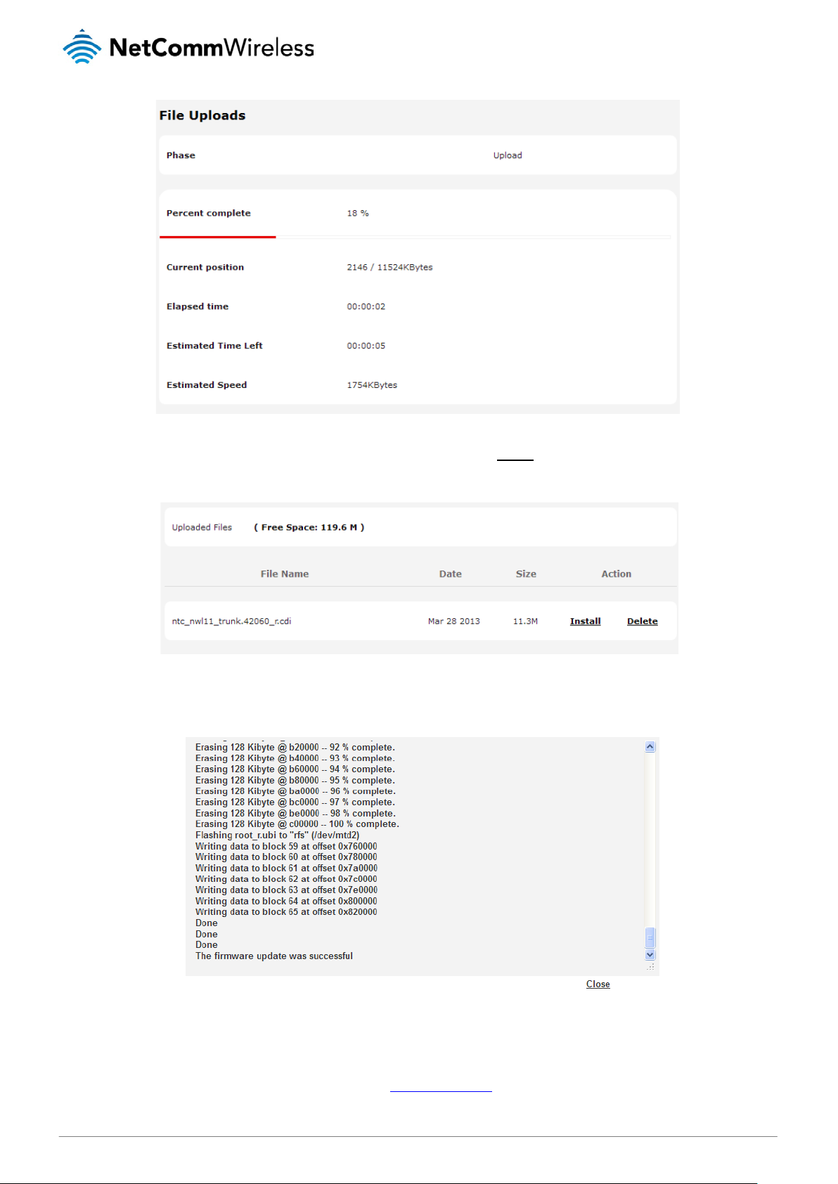
igure 81 - File upload
F
The recovery firmware image is listed in the Uploaded files section. Click the Install link to begin installing the recovery
firmware image and then click OK on the confirmation window that appears.
Figure 82 - Uploaded files
3. The recovery firmware image is flashed and when it is complete, the router displays “The firmware update was
successful” and returns to the main Upload screen.
Figure 83 - Recovery firmware flash process
4. Press and hold the reset button on the interface panel of the router for between 5 and 15 seconds until the all LEDs on
the front of the router start to flash on and off then release it. The router boots into the system recovery mode.
5. When the router has finished booting, navigate to http://192.168.1.1/
in your web browser. The router recovery console
is displayed.
www.netcommwireless.com
NetComm Wirel ess CDMA M2M Router
87
Page 88
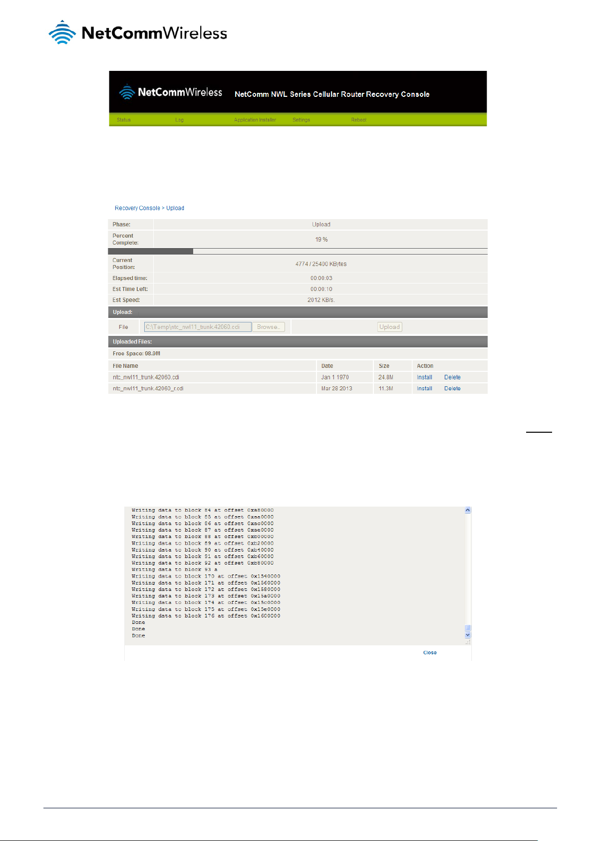
Figure 84 – NWL Series Router Recovery Console banner
6. Click the Application installer link from the menu bar at the top then click the Browse button. Locate the main
firmware image file on your computer and click Open. Click the Upload button to begin the firmware upload.
Figure 85 - Recovery console - Upload main firmware image
7. When the upload has completed, the screen refreshes to display the list of files on the router’s storage. Click the Install
link to the right of the main firmware image you uploaded and then click OK to confirm that you want to continue with
the installation.
8. The installation is complete when you see the words “Done” as per the screenshot below.
Figure 86 - Recovery console – installing main firmware image
9. Click the Reboot menu item from the top menu bar then click the Reboot button. Click OK to confirm the reboot of the
router. The CDMA M2M router boots up with the updated firmware.
NetComm Wirel ess CDMA M2M Router
88
www.netcommwireless.com
Page 89

Software applications manager
The Software applications ma nager page is used to provide details of any user installed packages on the router and allow them
to be uninstalled.
For more information on application development, contact NetComm Wireless about our Software Development Kit.
Figure 87 – Software applications manager
The Application name, Version number of the application, the architecture type and time of installation are all displayed. Clicking
the Package details link will display a pop-up window with further details of the package.
To uninstall any software applications, click the Uninstall link.
www.netcommwireless.com
NetComm Wirel ess CDMA M2M Router
89
Page 90

Administration settings
The Administration settings page is used to enable or disable the firewall, remote access contr ol, teln et acces s, ping responses
and logging to a remote syslog server.
NetComm Wirel ess CDMA M2M Router
90
Figure 88 - Administration page
www.netcommwireless.com
Page 91

ber between 1 and 65534 to use when accessing the router remotely over an HTTPS
Enter the IP address or hostname of the syslog server. You can also specify the port number after the
Sets the operation mode of the LEDs on the front panel of the router. To set the lights to operate at all
OPTION DEFINITION
Router firewall
Enable or disable the in-built firewall on the router. When enabled, the firewall performs stateful
packet inspection on inbound traffic from the wireless WAN and blocks all unknown services, that is,
all services not listed on the Services configuration page of the router.
With respect to the other Routing options on the Networking page, the firewall takes a low priority.
Enable router
firewall
Remote router access control
Enable HTTP
HTTP
management
port
Enable HTTPS Enable or disable remote HTTPS access to the router using a secure connection.
The priority of the firewall can be described as:
DMZ > MAC/IP/Port filtering rules > MAC/IP/Port filtering default rule > Router firewall rules
In other words, the firewall is of the lowest priority when compared to other manual routing
configurations. Therefore, a MAC/IP/Port filtering rule takes priority in the event that there is a conflict
of rules. When DMZ is enabled, MAC/IP/Port filtering rules and the router firewall are ignored but the
router will still honour the configuration of the Remote router access control settings described below.
Enable or disable remote HTTP access to the router. You can also set the port you would like remote
HTTP access to be available on.
Enter a port number between 1 and 65534 to use when accessing the router remotely.
Remote HTTPS
access port
Enable Telnet Enable or disable remote telnet (command line) access to the router.
Enable Ping Enable or disable remote ping responses on the WWAN connection.
Web User Interface account
Username
Password Enter the desired web user interface password.
Confirm
Password
Telnet account
Username
Password Enter the desired telnet access password.
Confirm
Password
Remote syslog server
IP / Hostname
[:PORT]
LED operation mode
Enter a port num
connection.
Use the drop down list to select the root or admin account to change its web user interface
password.
Re-enter the desired web user interface password.
Always displays root as this is the only account that can be used to access the router using telnet.
Re-enter the desired telnet access passw ord.
IP or hostname by enter ing a semi-colon and then the port number e.g. 192.168.1.102:514. If you do
not specify a port number, the router will use the default UDP port 514.
Mode
times, set this to Always on. To set the lights to turn off after a specified period, select Turn off after
timeout.
Table 24 - Administration configuration options
www.netcommwireless.com
NetComm Wirel ess CDMA M2M Router
91
Page 92

To access the router’s configuration pages remotely:
1. Open a new browser window and navigate to the WAN IP address and assigned port number of the router, for example
http://123.209.130.249:8080
Note: You can find the router’s WAN IP address by clicking on the “Status” menu. The Local field in the WWAN section
shows the router’s WAN IP address.
2. Enter the username and password to login to the router and click Log in.
Note: To perform functions like Firmware upgrade, device configuration backup and to restore and reset the router to
factory defaults, you must be logged in with the root manager account.
NetComm Wirel ess CDMA M2M Router
92
www.netcommwireless.com
Page 93

Reboot
The reboot option in the System section performs a soft reboot of the router. This can be useful if you have made configuration
changes you want to implement.
To reboot the router:
1. Click the System menu item from the top menu bar.
2. Click the Reboot button from the menu on the left side of the screen.
Figure 89 - Reboot menu option
3. The router displays a warning that you are about to perform a reboot. If you wish to proceed, click the Reboot button
then click OK on the confirmation window which appears.
Figure 90 - Reboot confirmation
Note: It can take up to 2 minutes for the router to reboot.
Logging out
To log out of the router, click the icon at the top right corner of the web user interface.
www.netcommwireless.com
NetComm Wirel ess CDMA M2M Router
93
Page 94

Appendix A: Tables
Table 1 - Document Revision Histor y ............................................................................................................................................. 2
Table 2 - Device Dime nsions .......................................................................................................................................................... 7
Table 3 - LED Indicators ................................................................................................................................................................. 8
Table 4 - Signal strength LED descriptions ..................................................................................................................................... 9
Table 5 – Interfaces ...................................................................................................................................................................... 10
Table 6 - PoE power classes ........................................................................................................................................................ 16
Table 7 - Locking power block pin outs ......................................................................................................................................... 16
Table 8 - Average power consumption figures.............................................................................................................................. 17
Table 9 - Management account login details ................................................................................................................................ 18
Table 10 - Status page item details .............................................................................................................................................. 21
Table 11 - Data connection item details ........................................................................................................................................ 23
Table 12 - Connect on demand - Connect and di sco nne ct t i mers de scri ptio ns ............................................................................ 29
Table 13 - Current MAC / IP / Port filtering rules in effect ............................................................................................................. 42
Table 14 - IPSec Configuration Items ........................................................................................................................................... 45
Table 15 - SMS Setup Settings ..................................................................................................................................................... 68
Table 16 - Inbox/Outbox icons ...................................................................................................................................................... 71
Table 17 - SMS Diagnostic Command Syntax .............................................................................................................................. 76
Table 18 - List of Valid SMS diagnostic commands ...................................................................................................................... 77
Table 19 - List of SMS diagnostics variables ................................................................................................................................ 78
Table 20 - Network types returned by get plmnscan SMS command ........................................................................................... 79
Table 21 - Operator status codes returned by get plmnscan SMS command ............................................................................... 79
Table 22 - SMS diagnostics example commands ......................................................................................................................... 81
Table 23 - System log detail levels ............................................................................................................................................... 83
Table 24 - Administration con fi gur ati on optio ns ............................................................................................................................ 91
Table 25 - LAN Management Default Settings.............................................................................................................................. 97
Table 26 - Web Interface Default Settings .................................................................................................................................... 97
Table 27 - Telnet Access .............................................................................................................................................................. 97
Table 28 - RJ-45 connector pin outs ........................................................................................................................................... 102
NetComm Wirel ess CDMA M2M Router
94
www.netcommwireless.com
Page 95

Appendix B: Device Mounting
Dimensions
The image below is at 100% scale and may be used as a template for mounting the device. All dimensions shown are in
millimetres.
www.netcommwireless.com
Figure 91 - Device mounting dimensions
NetComm Wirel ess CDMA M2M Router
95
Page 96

Appendix C: Mounting Bracket
The image below is at 100% scale and may be used as a template for mounting the bracket. All dimensio ns shown are in
millimetres.
NetComm Wirel ess CDMA M2M Router
96
Figure 92 - Mounting bracket
www.netcommwireless.com
Page 97

Appendix D: Default Settings
The following tables list the default settings for the CDMA M2M router.
LAN (MANAGEMENT)
Static IP Address: 192.168.1.1
Subnet Mask: 255.255.255.0
Default Gateway: 192.168.1.1
Table 25 - LAN Management Default Settings
Note: The admin manager account allows you to manage all settings of the router except functions such as firmware
upgrade, device configuration backup and restore and reset to factory default settings, which are privileged only to the
root manager account.
ADMIN MANAGER
ACCOUNT
Username: admin Username: root
Password: admin Password: admin
Table 26 - Web Interface Default Settings
CDMA M2M ROUTER TELNET
ACCESS
Username: root
Password: admin
Table 27 - Telnet Access
ROOT MANAGER
ACCOUNT
www.netcommwireless.com
NetComm Wirel ess CDMA M2M Router
97
Page 98

Restoring factory default settings
Restoring factory defaults will reset the CDMA M2M router to its factory default configur atio n. You may encounter a situation
where you need to restore the factory defaults on your CDMA M2M router such as:
You have lost your username and password and are unable to login to the web configuration page;
You are asked to perform a factory reset by support staff.
There are two methods you can use to restore factory default settings on your CDMA M2M router:
Using the web-based user interface
Using the reset button on the interface panel of the router
Using the web-based user interface
To restore your router to its factory default settings, please follow these steps:
1. Open a browser window and navigate to the IP address of the router (default address is http://192.168.1.1
the router using
2. Click the System item from the top menu bar, then System configuration on the left menu and then click Settings
backup and restore.
3. Under the Restore factory defaults section, click the Restore defaults button. The router asks you to confirm that
you wish to restore factory defaults. Click OK to continue. The router sets all settings to default. Click OK again to
reboot the router.
4. When the Power light returns to a steady red, the reset is complete. The default settings are now restored.
Using the reset button on the interface panel of the router
Use a pen to depress the Reset button on the device for 15-20 seconds. The router will restore the factory default settings and
reboot.
When you have reset your CDMA M2M router to its default settings you will be able to access the device’s configuration web
interface using http://192.168.1.1
root
as the User Name and
with username admin or root and password admin.
admin
as the password.
). Login to
NetComm Wirel ess CDMA M2M Router
98
www.netcommwireless.com
Page 99

Recovery mode
The CDMA M2M router features two independent operating systems, each with its own file systems. These two systems are
referred to as 'Main' and 'Recovery'. It is always possible to use one in order to restore the other in the event that one system
becomes damaged or corrupted (such as during a firmware upgrade failure).
Both systems have Web interfaces that can be used to manipulate the other inactive system. The CDMA M2M router starts up
by default in the Main system mode, however the router may be triggered to start in recovery mode if desired.
To start the router in recovery mode:
1. Press and hold the physical reset button on the interface panel of the router for 5 to 15 seconds. When the LEDs on
the front panel change to amber and countdown in a sequence, release the reset button. The router then boots into
recovery mode.
2. In your browser, navigate to http://192.168.1.1
regardless of the IP address that was configured in the main system. The router’s recovery console is displayed.
. The router’s recovery mode is hardcoded to use this address
Figure 93 - Recovery console
The recovery console provides limited functionality. Basic status information is available, as well as access to the System log for
troubleshooting. The Application Installer can be used to upload and install different firmware, allowing you to roll back to a
previous firmware in the event that an upgrade fails. The Settings menu provides the ability to reset the router to factory default
settings and the Reboot tab allows you to perform a soft reboot of the router.
www.netcommwireless.com
NetComm Wirel ess CDMA M2M Router
99
Page 100

Appendix E: HTTPS Uploading a self-signed
certificate
If you have your own self-signed certificate or one purchase d elsewhere and signed by a Certificate Authority, you can upload it
to the CDMA M2M Router using the Upload page.
Note: Your key and certificate files must be named server.key and server.crt respectively otherwise they will not work.
To upload your certificate:
1. Click on the System item from the top menu bar. From the side menu bar, sel ect System configuration and then
Upload. The file upload screen is displayed.
Figure 94 - Upload page
2. Click the Browse button and locate your server certificate file and click Open.
Figure 95 - Browse for server.crt
NetComm Wirel ess CDMA M2M Router
100
www.netcommwireless.com
 Loading...