

Page 1

Quick Start Guide
NTC-100
4G LTE Cat M1/NB1 Industrial IoT Serial Modem
Page 2

Quick start guide
This quick start guide will help you set up and connect your device quickly and easily.
More advanced set up instructions can be found in the user guide which can be
downloaded from www.netcommwireless.com/product/m2m/ntc-100.
Package contents
The NTC-100 package includes:
1 x NTC-100
1 x Y-cable
(Nano-t to DE-9 and DC power input)
| Industrial IoT
2
1 x Torx screw
1 x Quick Start Guide
1 x DIN rail mounting bracket
Page 3

NTC-100 4G LTE Cat M1/NB1 Industrial IoT Serial Modem
Prerequisites
Depending on your circumstances, you may require some of the following items to
complete the installation of the NTC-100 serial modem:
• An AC/DC power adapter,
- 2.1mm centre positive jack,
- 100-240V AC : 12V DC/1.5A (used in conjunction
with the included Y-cable)
• A suitable cellular antenna such as the NANT-00001-000
(LTE Tube Antenna)
• A standard USB to USB Micro Type B cable
• Additional screws and fasteners
• A Windows PC or other device with an available serial or USB port
• A terminal emulation client such as PuTTY
• A T6 Torx driver to secure the SIM slot (optional)
| Industrial IoT
3
Page 4

Device Overview
10-pin NANO-t (locking) connector
50 mm
(power and serial interface)
84 mm
89 mm
| Industrial IoT
4
Cellular antenna
connector
Page 5

SIM card slot
NTC-100 4G LTE Cat M1/NB1 Industrial IoT Serial Modem
Status
Network
21 mm
Micro USB 2.0 port
Reset button
| Industrial IoT
5
Page 6

Installation
Connecting the antenna
Connect the antenna to the SMA connector on the NTC-100 serial modem by
placing it on the SMA connector and turning it in a clockwise direction.
| Industrial IoT
6
Page 7

NTC-100 4G LTE Cat M1/NB1 Industrial IoT Serial Modem
Inserting the SIM card
1. Lift the cover from the right side. This reveals the Micro USB 2.0 port and the
reset button.
2. Slide the cover to the right to reveal the SIM card slot.
| Industrial IoT
7
Page 8
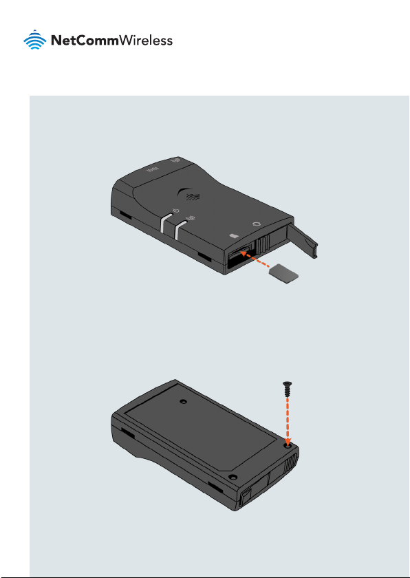
3. Insert the SIM card into the slot with the gold SIM conductor pins facing
down. Push the SIM card in until it locks in place. To remove the SIM card,
push it in again and it will unlock.
4. Slide the cover back to the left and then push the right side closed.
5. To lock the protective cover, fasten the provided Torx screw into the hole
below the SIM card slot on the bottom of the device using a T6 Torx driver.
| Industrial IoT
8
Page 9

NTC-100 4G LTE Cat M1/NB1 Industrial IoT Serial Modem
Power and serial communication options
The NTC-100 serial modem may be connected and powered by:
• The built-in 5V Micro USB socket (USB cable not included)
OR
• The 10-pin power/data connector using the included Y-cable.
Powering the NTC-100 serial modem via 5V Micro
USB socket
The NTC-100 serial modem features a USB port which can optionally be used for
serial connectivity, terminal emulation or for establishing a PPP internet connection.
The USB port enumerates a number of endpoints after the USB port driver is
installed.
Connect a standard USB to USB Micro Type B cable (not included) between the
NTC-100 serial modem and a powered USB port on your device (e.g. computer).
The USB cable provides the NTC-100 serial modem with power and an emulated
serial port input.
| Industrial IoT
9
Page 10

1. For USB port communication, you must install a driver compatible with the
NTC-100 serial modem’s embedded Quectel BG96 cellular module. The
Windows drivers are available from the NTC-100 serial modem product page
on the NetComm Wireless website (www.netcommwireless.com/product/
m2m/ntc-100).
2. After the download has completed, install the driver by double-clicking on the
downloaded le and following the installer prompts.
3. Open the Control Panel and then Device Manager. The NTC-100 serial
modem appears under Ports with three Quectel USB entries.
The COM port used for each port is displayed in brackets next to each port type.
For terminal access, take note of the COM port assigned to the Quectel USB
AT Port. In the screenshot above, it is COM11. For further instructions, see the
Accessing the NTC-100 via terminal emulator section of this guide.
| Industrial IoT
10
Page 11

NTC-100 4G LTE Cat M1/NB1 Industrial IoT Serial Modem
Powering the NTC-100 via Y-cable
The included Y-cable features a breakout cable providing a DC Jack. Connect the
Serial plug to a Serial port on your device (e.g. computer) and then connect a 4.5-
36V power source to the DC Jack to power the unit. Connect the 10-pin plug into
the 10-pin connector on the NTC-100 serial modem.
After powering up, the NTC-100 serial modem is ready to establish a serial
communication link. See the next section for instructions on accessing the NTC100 serial modem via terminal emulator.
Conguring the NTC-100 via SMS
A full list of SMS commands used to control and congure the NTC-100 are
available in the User Guide.
| Industrial IoT
11
Page 12

Accessing the NTC-100 via terminal emulator
To access the NTC-100 using a terminal emulator:
1. Using your terminal emulator, create a new connection to the COM port
assigned to the connected serial port, with the bitrate set to 115200.
2. If you are accessing the NTC-100 via the USB interface, type AT and Press
Enter in the terminal window that appears. If the NTC-100 is connected, it
replies with OK. Note that you can access only module AT commands from the
USB port.
If you are accessing the NTC-100 via the Serial Y cable, type any character.
The terminal prompts you for a username and password. At the username
prompt, type root then press Enter. At the password prompt, type admin
then press Enter. When logged in, type AT. The NTC-100 replies with OK.
From the Serial interface, you can access module AT commands and custom
application AT commands.
Further AT commands are available in the supporting documentation on the
NetComm Wireless website at
| Industrial IoT
12
www.netcommwireless.com/product/m2m/ntc-100
Page 13

NTC-100 4G LTE Cat M1/NB1 Industrial IoT Serial Modem
Mounting options
The NTC-100 serial modem can be mounted on a wall, DIN rail or a pole by using
the mounting bracket. The mounting bracket is made from polyamide, a exible
material.
DIN rail mounting
The NTC-100 serial modem mounting bracket has been designed to t a TS 35
Type-O DIN rail with a 25mm core.
Bend the mounting bracket at the bend line so that the ridges are able to ‘hold’
onto the DIN rail edges as per the diagram below. Alternatively, if the end of the
DIN rail is open, you can slide the bracket on to the rail. You also have the option
of securing the mounting bracket further by screwing it into place on the rail.
| Industrial IoT
13
Page 14

Wall mounting
Select the location where you would like to attach the NTC-100 serial modem.
Attach the mounting bracket to the chosen wall or ceiling by using the 3 screw
holes (screws not included).
Pole mounting
Use cable ties (max 4mm width) through the holes on the mounting bracket to afx
the NTC-100 to a pole.
| Industrial IoT
14
Page 15

NTC-100 4G LTE Cat M1/NB1 Industrial IoT Serial Modem
Inserting the
NTC-100 into the
mounting bracket
Once the bracket is attached to the DIN rail, wall or pole, snap the NTC-100 into
the mounting bracket to hold it in place. The NTC-100 can be snapped into the
mounting bracket in two ways, as shown below.
| Industrial IoT
15
Page 16

Pin outs
10-pin power/data connector
Note: The image to the left depicts the
NanoFit header on the NTC-100 as
viewed from the side of the device.
Pin map
Nano-Fit Pin
1 2 Green RXD A RD-
2 1 Blue DCD B RD+
3 7 Yellow RTS
4 9 Orange RI
5 5 Black GND GND GND
6 4 Brown DTR TD-
7 3 White TXD TD+
8 6 Purple DSR
9 8 Grey CTS
10 - Red DC In DC In DC In
| Industrial IoT
16
DE-9 Pin
Wire Colour
RS-232 RS-485 RS-422
Page 17

USB
1. VUSB 5V
2. USB Data N
3. USB Data P
4. USB ID
5. GND
NTC-100 4G LTE Cat M1/NB1 Industrial IoT Serial Modem
| Industrial IoT
17
Page 18

LED indicators
The NTC-100 serial modem uses two LEDs to display the current system and
connection status.
Status LED
Status
Off The power is off.
Flashing Red Device error.
Flashing Green The NTC-100 is powering up.
Solid Green The NTC-100 is powered up and ready for connection.
Description
Network LED
Functions
Status
Off No signal.
Intermittently Red (on 30
seconds, off 30 seconds)
Blinking Red (displays red
once every 2 seconds)
Blinking Red, Amber or
Green
Flashing Red, Amber or
Green
| Industrial IoT
18
Description
No SIM detected.
SIM detected but not connected.
Registered to network with poor (red), medium
(amber) or strong (green) signal strength.
Data being transferred with poor (red), medium
(amber) or strong (green) signal strength.
Page 19

Signal Strength
NTC-100 4G LTE Cat M1/NB1 Industrial IoT Serial Modem
Network LED Colour
Signal Strength
Green High
Amber Medium
Red Low
OFF No signal
Accessories
Additional cables are available for purchase separately. Contact your NetComm
Wireless sales representative to order additional cables. Refer to the table below
for the product codes.
Accessory Name
Y-Cable (DE-9 female to 10-pin + DC5521 female) MCBL-00004-000
Straight cable (8P8C to 10-pin) MCBL-00003-000
Straight cable (10-pin to open cable) MCBL-00005-000
Product Code
| Industrial IoT
19
Page 20

Regulatory information
FCC regulations
Federal Communications Commission Notice (United States): Before a wireless
device model is available for sale to the public, it must be tested and certied to
the FCC that it does not exceed the limit established by the government-adopted
requirement for safe exposure.
This device complies with part 15 of the FCC Rules. Operation is subject to the
following two conditions:
(1) This device may not cause harmful interference, and
(2) this device must accept any interference received, including interference that
may cause undesired operation.
This equipment has been tested and found to comply with the limits for a Class
B digital device, pursuant to Part 15 of the FCC Rules. These limits are designed
to provide reasonable protection against harmful interference in a residential
installation. This equipment generates, uses and can radiate radio frequency
energy and, if not installed and used in accordance with the instructions,
may cause harmful interference to radio communications. However, there is
no guarantee that interference will not occur in a particular installation. If this
equipment does cause harmful interference to radio or television reception, which
can be determined by turning the equipment off and on, the user is encouraged to
try to correct the interference by one or more of the following measures:
| Industrial IoT
20
Page 21

NTC-100 4G LTE Cat M1/NB1 Industrial IoT Serial Modem
• Reorientate or relocate the receiving antenna.
• Increase the separation between the equipment and receiver.
• Connect the equipment into an outlet on a circuit different from that to which the
receiver is connected.
• Consult the dealer or an experienced radio/TV technician for help.
FCC Caution: Any changes or modications not expressly approved by the
party responsible for compliance could void the user‘s authority to operate the
equipment.
RF Exposure
Your device contains a transmitter and a receiver. When it is on, it receives and
transmits RF energy. When you communicate with your device, the system handling
your connection controls the power level at which your device transmits.
• This device meets the government’s requirements for exposure to radio waves.
• This device is designed and manufactured not to exceed the emission limits
for exposure to radio frequency (RF) energy set by the Federal Communications
Commission of the U.S. Government.
• This device complies with FCC radiation exposure limits set forth for an
uncontrolled environment. To ensure compliance with RF exposure guidelines the
device must be used with a minimum of 20cm separation from the body. Failure to
observe these instructions could result in your RF exposure exceeding the relevant
guideline limits.
This transmitter must not be co-located or operating in conjunction with any other
antenna or transmitter.
External antenna (transmitters equipped with detachable antennas)
Any external antenna used for this transmitter must be installed to provide a
separation distance of at least 20cm from all persons and must not be co-located
| Industrial IoT
21
Page 22

or operated in conjunction with any other antenna or transmitter. Please consult
the health and safety guide of the chosen antenna for specic body separation
guidelines as a greater distance of separation may be required for high-gain
antennas.
Any external antenna gain must meet RF exposure and maximum radiated output
power limits of the applicable rule section. The maximum antenna gain for this
device as reported to the FCC is:
FREQUENCY (MHz) GAIN (dBi)
698 - 798 4.71
824 - 960 3.13
1710 - 2100 3.42
2400 - 2700 4.32
Company Contact Details
NetComm Wireless Limited, 1000 Sawgrass Corporate Parkway, Suite 500
Sunrise, Florida 33323, USA
Phone: +1 320 566 0316
IC regulations
This Class B digital apparatus complies with Canadian ICES-003.
Cet appareil numérique de la classe B est conforme à la norme NMB-003 du
Canada.
This device complies with ISED licence-exempt RSS standard(s). Operation is
subject to the following two conditions:
Le présent appareil est conforme aux CNR d’Industrie Canada applicables
| Industrial IoT
22
aux appareils radio exempts de licence. L’exploitation est autorisée aux deux
Page 23

NTC-100 4G LTE Cat M1/NB1 Industrial IoT Serial Modem
conditions suivantes:
(1) this device may not cause interference, and
(1) l’appareil ne doit pas produire de brouillage, et
(2) this device must accept any interference, including interference that may cause
undesired operation of the device.
(2) l’utilisateur de l’appareil doit accepter tout brouillage radioélectrique subi, même
si le brouillage est susceptible d’en compromettre le fonctionnement.”
RF Exposure Information (MPE):
This equipment complies with ISED radiation exposure limits set forth for an
uncontrolled environment.
Cet équipement est conforme aux limites d’exposition aux rayonnements ISED
établies pour un environnement non contrôlé.
This equipment should be installed and operated with minimum distance 20 cm
between the radiator & your body.
Cet équipement doit être installé et utilisé avec une distance minimale de 20 cm
entre le radiateur et votre corps.
External antenna - RSS-Gen 8.3 (transmitters equipped with detachable
antennas)
This radio transmitter has been approved by ISED to operate with the antenna
types listed below with the maximum permissible gain and required antenna
impedance for each antenna type indicated.
Le présent émetteur radio a été approuvé par ISED pour fonctionner avec les
types d’antenne énumérés ci-dessous et ayant un gain admissible maximal et
l’impédance requise pour chaque type d’antenne.
| Industrial IoT
23
Page 24

Antenna types not included in this list, having a gain greater than the maximum gain
indicated for that type, are strictly prohibited for use with this device.
Les types d’antenne non inclus dans cette liste, ou dont le gain est supérieur au
gain maximal indiqué, sont strictement interdits pour l’exploitation de l’émetteur.
Antenna types / Type d’antennes:
Antenna gain in dBi / Gain d’antenne (en dBi):
FREQUENCY (MHz) GAIN (dBi)
698 - 798 4.71
824 - 960 3.13
1710 - 2100 3.42
2400 - 2700 4.32
| Industrial IoT
24
Page 25

NTC-100 4G LTE Cat M1/NB1 Industrial IoT Serial Modem
THIS PAGE INTENTIONALLY LEFT BLANK.
| Industrial IoT
25
Page 26

THIS PAGE INTENTIONALLY LEFT BLANK.
| Industrial IoT
26
Page 27

NTC-100 4G LTE Cat M1/NB1 Industrial IoT Serial Modem
THIS PAGE INTENTIONALLY LEFT BLANK.
| Industrial IoT
27
Page 28

Product Warranty
For warranty information please visit
https://support.netcommwireless.com/warranty-info
Technical Support
For rmware updates or if you have any technical difculties with your product,
please refer to the support section of our website.
http://support.netcommwireless.com/
NETCOMM WIRELESS LIMITED ABN 85 002 490 486
Head Ofce, 18-20 Orion Road
Lane Cove, Sydney, NSW 2066, Australia
p: +61 2 8205 3888 f: +61 2 9424 2010
e: m2msales@netcommwireless.com
www.netcommwireless.com
MPRT-00003-000 Rev14
 Loading...