

Page 1
NetCommWireless
Quick Start Guide
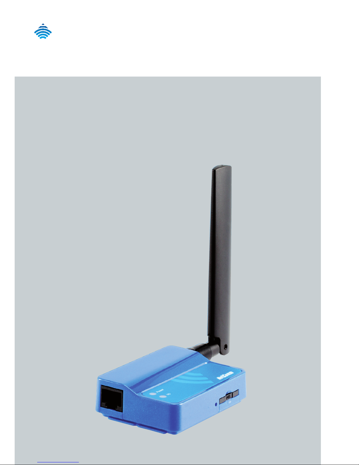
NTC-4000 Series -
M2M Intelligent Serial Router
Page 2
| Wireless M2M
2
NetCommWireless
Quick Start Guide
This guide covers the NTC-4000 Series M2M WiFi Rotuers. This guide
provides a series of step by step instructions to ensure the conguration
of your router goes as smoothly as possible.
Please check that you have received all the items in your package:
The NTC-4000 series package consists of:
NTC-4000 Series Modem Device
RS-232 Data/Power Cable 1m
SMA Antenna
Mounting bracket
Quick Start Guide
If any of these items are missing, please contact NetComm Wireless
Technical Support.
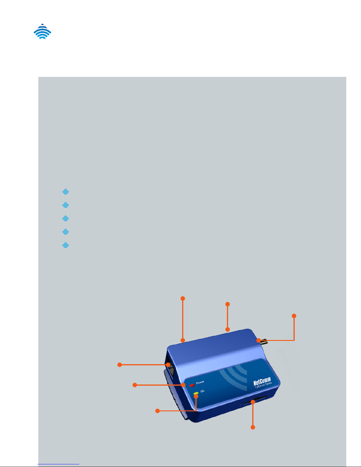
Reset
Button
SIM card Tray
Cellular Data LED
Power LED
RJ-45 port
(serial RS-232 data and
DC power input)
Mini
USB port
SMA
antenna
connector
Page 3
| Wireless M2M
3
NTC-4000 Series - M2M Intelligent Serial Router
Installing your Router
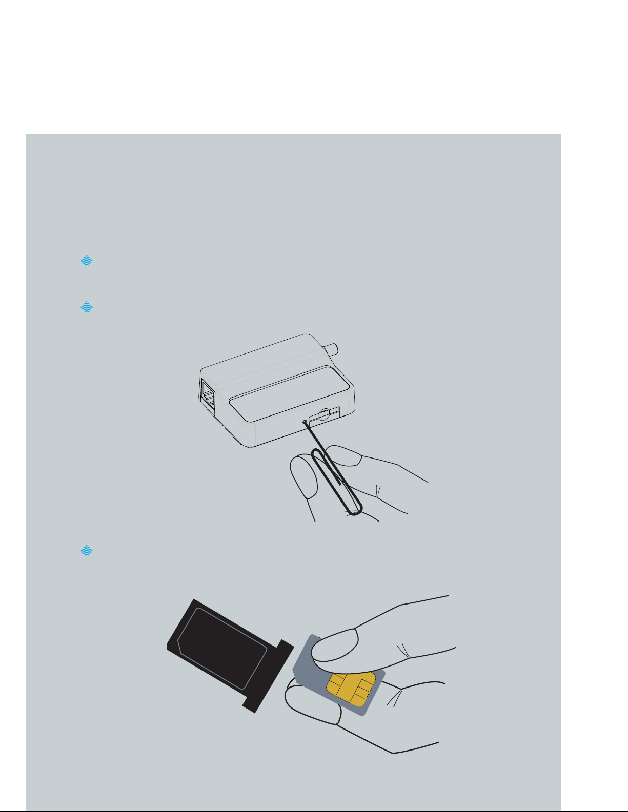
Inserting the SIM card
Please ensure that the NTC-4000 is not connected to the power
cable before proceeding.
Push the small yellow button besides the SIM card holder.
Insert the SIM card into the holder with the SIM conductor pins
facing up.
Page 4
| Wireless M2M
4
NetCommWireless
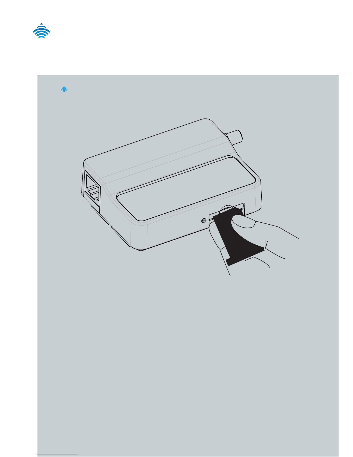
Insert the SIM card holder with the SIM conductor pins facing
down into the NTC-4000.
Page 5

| Wireless M2M
5
NTC-4000 Series - M2M Intelligent Serial Router
Connecting the Data/
Power cable
Connect the included antenna to the SMA connector of the
NTC-4000.
Plug the included RS-232 data/power cable into the RJ-45
socket of the NTC-4000 and then plug the serial port (DB9) end
of the same cable into the COM port of the device you would like
to connect to.
Connect a compatible power adapter to the DC power jack
(2.1mm barrel) of the RS-232 data/power cable and then plug the
power adapter into a power outlet.
WARNING
Please note: It is not possible to utilise the mini-USB and Serial connection concurrently.
Make sure any open connection on the Serial port is disabled before connecting via the
mini-USB cable.
Page 6

| Wireless M2M
6
NetCommWireless
Connecting via mini USB
Please refer to the NTC-4000 Series User Manual for instructions on
utilising the mini USB connection.
Please note: The mini USB cable is not supplied with the NTC-4000 Series.
Page 7

| Wireless M2M
7
NTC-4000 Series - M2M Intelligent Serial Router
Communicating with the
NTC-4000 Series
Any terminal emulator can be utilised to facilitate communication
to the NTC-4000 Series. In the example below, HyperTerminal from
Windows XP is shown.
Click on the Start button and then navigate to the Accessories
item and then Communications.
Click on the HyperTerminal item.
Enter a name for the connection prole (for example: NTC-4000)
and click OK.
On the Connect to window, select the COM port the NTC-4000
Series is connected to in the Connect using dropdown menu.
Page 8

| Wireless M2M
8
NetCommWireless
On the COM port settings window that appears, select 115200 in
the Bits per second dropdown menu.
The terminal window should then display indicating a connection is
open to the NTC-4000 Series. This can be tested by entering the
command at+i and receiving the response I/OK as shown below:
You can now use the enhanced AT command set to congure
or perform tasks on the NTC-4000 Series. Please refer to the AT
Command Set guide for more information on the functions available.
If you are unable to type at+i, check that you have selected the correct
COM port to attempt to connect on. This should be the physical COM
port with the supplied DB-9 cable attached.
Page 9

| Wireless M2M
9
NTC-4000 Series - M2M Intelligent Serial Router
AT Commands
Please refer to the AT Command Set guide available from the Downloads
tab at: www.netcommwireless.com/product/m2m/ntc-4000
This guide contains a full list of the supported AT Commands available
with the NTC-4000 series.
Page 10

| Wireless M2M
10
NetCommWireless
Mounting Options
The NTC-4000 series modem can be mounted on the wall or a DIN rail
by using the mounting bracket. The mounting bracket is made from
polyamide, which is a exible material.
Mounting the NTC-4000 series modem is as simple as bending the
mounting bracket to snap into place on the Type-O (Top Hat) DIN rail.
This holds the NTC-4000 series modem in place securely.
Alternatively, the mounting bracket can be screwed onto a wall to
provide a permanent xture.
DIN rail mounting
The NTC-4000 Series mounting bracket has been designed to t a TS
35 Type-O DIN rail with a 25mm core.
Bend / Flex the mounting bracket at the bend line so that
the ridges are able to hold onto the DIN rail edges as per
the diagram above. You also have the option of securing the
mounting backet further by screwing it into place on the rail.
DIN Rail
Page 11

| Wireless M2M
11
NTC-4000 Series - M2M Intelligent Serial Router
Once the bracket is attached to the DIN rail, slide the
NTC-4000 Series modem into the mounting bracket to securely
x it in place.
Page 12

| Wireless M2M
12
NetCommWireless
Wall Mounting
Select the location you would like to attach the NTC-4000
Series modem to. Attach the mounting bracket to the chosen
wall or ceiling by using the 4 screw holes (screws not included).
LED Indicators
The NTC-4000 Series uses two LEDs to display the current system and
connection status.
LED
Indicator
Colour Denition
Power Off The Power is Off
Red The Power is on and the NTC-4000
is operating normally
3G Off The NTC-4908 is not connected to
a 3G network
Slow ashing green The NTC-4908 is attempting to
connect to a 3G network
Quick ashing green Data is moving across the 3G
connection
Page 13

| Wireless M2M
13
NTC-4000 Series - M2M Intelligent Serial Router
Technical Specications
The following table lists the hardware specications of the NTC-
4000 series.
Model NetComm NTC-4000 Series
CPU Connect One iChip™ CO2128SEC (ARM7,
embedded IP stack)
Modem Chipset/Module Qualcomm MSM6290 / Sierra Wireless MC8790
UMTS bands Tri-band HSDPA / HSUPA / UMTS 850/1900/2100MHz
GSM bands Quad-band EDGE/GPRS/GSM 850/900/1800/1900MHz
Maximum Data Throughput
/ 3G Radio interface
7.2Mbps downlink / 5.76Mbps uplink
Maximum Data Throughput
/ Serial RS232 interface
Auto baud rate - 115,200 / 57,600 / 38,400 / 19,200 /
9,600 /4,800 / 2,400 bps
Connectivity 1x RJ-45 port (incl. DB-9 adapter) for serial RS-232
connections | 1x Mini USB console port
SIM Card Reader Lockable tray, supports standard USIM/SIM
Antenna connector 1x SMA
LED Indicators Power, 3G Status
Operating Temperature Normal: -20 ~ 55 °C
Power input 8 ~ 56 V DC
Dimensions & Weight 74 x 57 x 24 mm / 85g (w/o mounting bracket
and antenna)
Regulatory Compliancy A-tick, RoHS compliant
Page 14

| Wireless M2M
14
NetCommWireless
RJ45 Connector
The RJ-45 connector provides a serial connection utilising 2 pins
(as shown below) to provide power.
PIN8—PIN1
Pin Signal Description
1 VCC Input voltage 8VDC - 56VDC
2 DCD Data Carrier Detect
3 DTR Not Used
4 GND Common Ground
5 RXD Serial Data out
6 TXD Serial Data in
7 RTS Ready to Send
8 CTS Clear to Send
Page 15

| Wireless M2M
15
NTC-4000 Series - M2M Intelligent Serial Router
Mini USB Connector
The mini USB connector provides a USB based virtual COM port to
facilitate communications to the NTC-4000 series in the event a COM
port. It utilises a standard mini USB pin out conguration.
PIN1—PIN5
Pin Signal
1 VIN
2 D-
3 D+
4 N/C
5 GND
Page 16

| Wireless M2M
16
NetCommWireless
RJ-45 to DB-9 Serial/Power
Adapter Cable
The NTC-4000 Series uses a RJ-45 to DB-9 serial cable to facilitate
communications to an attached device. Pins 1 and 4 are used to supply
power to the NTC-4000 Series.
87654321
CTS- RTS
RTS-CTS
TXD-RXD
RXD-TXD
GND-GND-PWR
DCD
DTR
.PWR
RJ-45
DB-9
5
678
34
9
12
Page 17

| Wireless M2M
17
NTC-4000 Series - M2M Intelligent Serial Router
DB9 Signals RJ45 Description
1 DCD 2 Data Carrier Detect
2 RXD 5 Serial Data Out
3 TXD 6 Serial Data In
4 DTR 3 Data Terminal Ready
5 GND 4 Common Ground GND (Power Ground)
6 DSR NA Not Used
7 RTS 7 Request to Send (received by the NTC-4000)
8 CTS 8 Clear to Send (transmitted by the NTC-4000)
9 RI Not Used
Power 1 Red Wire: VCC (Input voltage from 8V – 56VDC)
4 Black wire: GND (Power Ground)
Page 18

| Wireless M2M
18
NetCommWireless
Product Warranty
NetComm Wireless products have a standard 12 months warranty
from date of purchase.
Technical Support
For rmware updates or if you have any technical difculties with
your product, please refer to the support section of our website.
http://support.netcommwireless.com/
product/m2m/ntc-4000
NETCOMM WIRELESS LIMITED ABN 85 002 490 486
Head Ofce, 18-20 Orion Road
Lane Cove, Sydney, NSW 2066, Australia
p: +61 2 8205 3888 f: +61 2 9424 2010
e: m2msales@netcommwireless.com
www.netcommwireless.com
 Loading...