

Page 1
Quick Start Guide
4G M2M Router
NTC-140-02
Page 2

| Wireless M2M
2
Quick start guide
This quick start guide is designed to get you up and running quickly with your new
NTC-140-02 router. More advanced set up instructions are provided in the user
guide which can be opened by clicking on the Help tab on the Web-UI, or can be
downloaded from
http://www.netcommwireless.com/product/m2m/ntc-140
Package contents
All NTC-140-02 packages include:
1 x NetComm Wireless NTC-140-02 router
2 x 3G/4G antennas
1 x 1.5m Black Ethernet cable
1 x DIN rail mounting bracket
1 x Quick start guide
1 x Power supply cable with tted Molex connector
Page 3
| Wireless M2M
3
NTC-140-02 - 4G M2M Router
-
i
I/O
GPS
USB
LAN LAN/WAN
Cellular Main
SIM
µSD
Cellular AUX
+
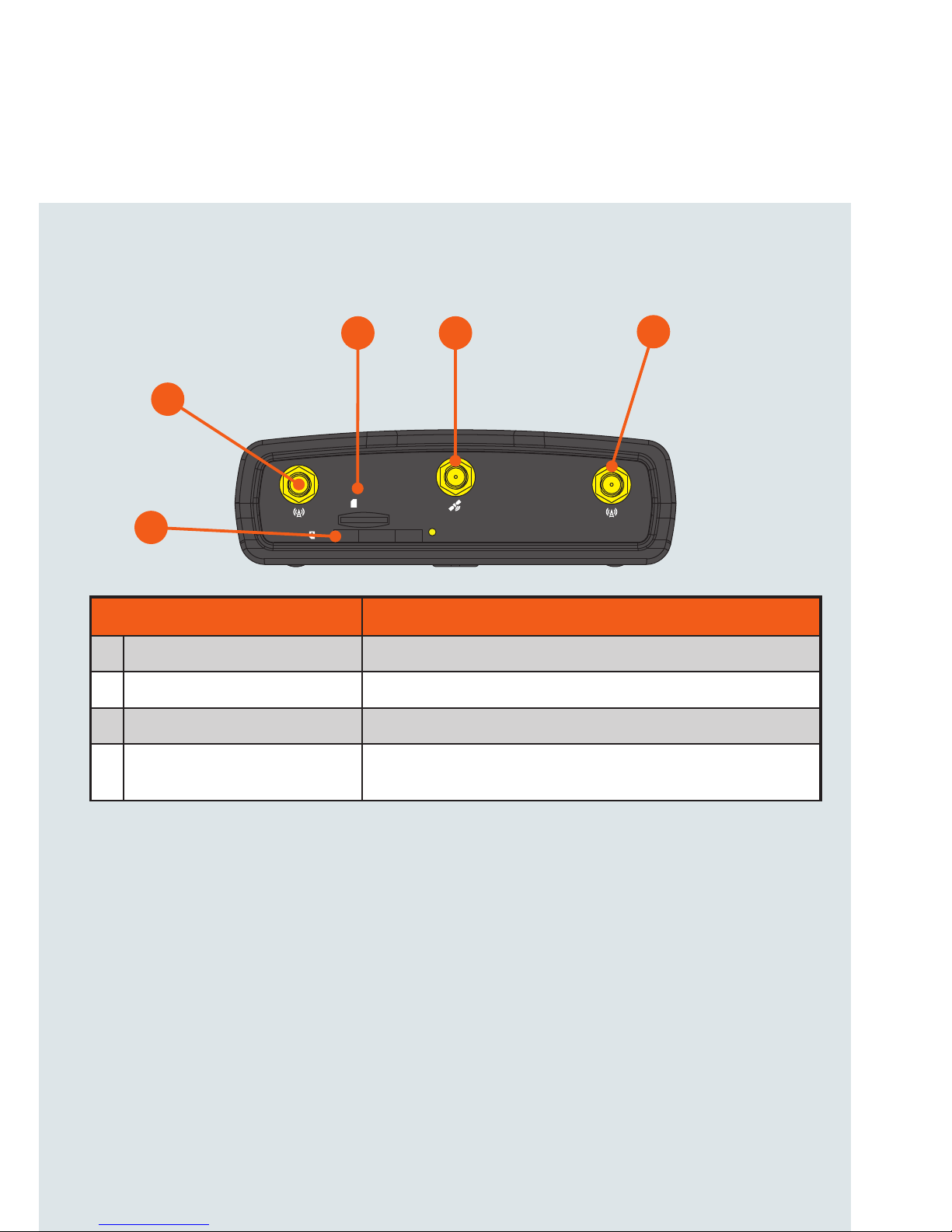
Device overview
ITEM DESCRIPTION
1 3G/4G antenna connectors SMA female connector for 3G/4G antennas.
2 GPS antenna connector SMA female connector for GPS antenna.
3 SIM card slot Insert SIM card here.
4 MicroSD card slot Insert a MicroSD card here to provide additional storage
(Optional).
2
1
3
1
4
Page 4
| Wireless M2M
4
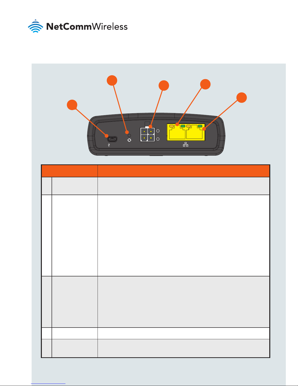
ITEM DESCRIPTION
1 Mini USB 2.0
OTG port
Provides connectivity for optional external storage or a USB Ethernet
dongle. Supplies up to 0.5A to connected device.
2 Reset button Press and hold for less than 5 seconds to reboot to normal mode.
The LEDs are green and extinguish in sequence to indicate that the
router will reboot normally if the button is released during this period.
Press and hold for 5 to 15 seconds to reboot to recovery mode.
The LEDs are amber and extinguish in sequence to indicate that the
router will reboot to recovery mode if the button is released during
this period.
Press and hold for 15 to 20 seconds to reset the router to factory
default settings. The LEDs are red and extinguish in sequence to
indicate that the router will reset to factory default settings if the
button is released during this period.
3 Molex Mini-Fit™
receptacle
Connect the provided power supply here. The Molex receptacle
provides:
• Ground (−)
• Power (+)
• I/O terminal
• (i) ignition input detection terminal.
4 LAN port LAN port for wired Ethernet clients.
5 LAN/WAN port LAN or WAN port for wired Ethernet clients or to bridge another
network connection.
-
i
I/O
USB
LAN LAN/WAN
+
1
2
5
3
4
Page 5
| Wireless M2M
5
NTC-140-02 - 4G M2M Router
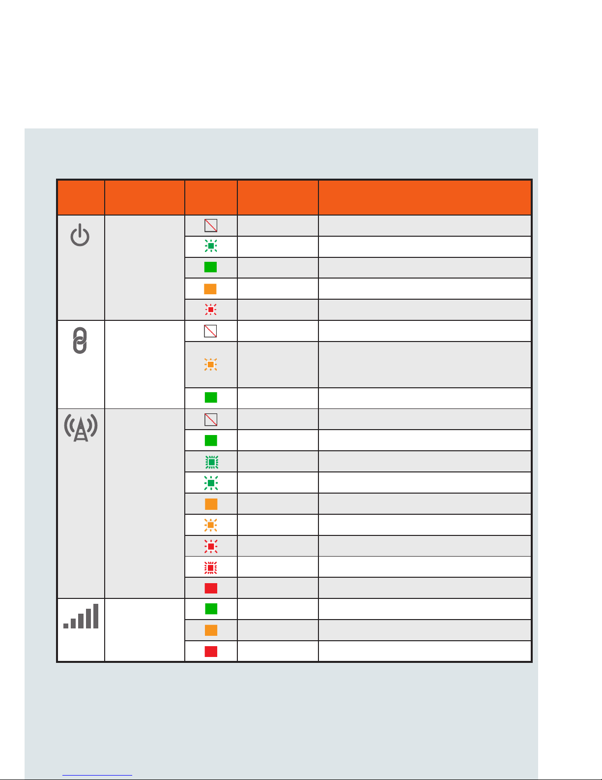
Overview of LED indicators
LED
ICON
NAME
COLOR
STATE DESCRIPTION
Power
Off Power off
Double ash Powering up
On Power on
On Power on in recovery mode
Slow ashing Hardware error, such as SIM not inserted.
GPS/
Customisable
LED
Off GPS function disabled
Slow ashing
GPS function is enabled but no satellite
detected
On Satellite detected, location acquired
Network
Off Radio Off
On Connected via WWAN
Blinking1 Trafc via WWAN
Slow ashing Connecting PDP
On Registered on Network
Slow ashing Registering network
Slow ashing SIM PIN locked
Fast ashing SIM PUK locked
On Can’t connect
Signal
strength
On LTE signal
On WCDMA signal
On GSM signal
1 The term “blinking” means that the LED may pulse, with the intervals that the LED is on and off not being equal. The
term “ashing” means that the LED turns on and off at equal intervals.
Page 6

| Wireless M2M
6
Power supply cable
The included power supply cable has colour-coded breakout wires which can be
terminated to provide power, ignition detection and input/output functionality.
The picture below outlines the polarity and functions of the wires.
Power
(+)
Ground
(−)
I/O
Ignition
Page 7

| Wireless M2M
7
NTC-140-02 - 4G M2M Router
-
i
I/O
GPS
USB
LAN LAN/WAN
Cellular Main
SIM
µSD
Cellular AUX
+
Installing your device
Step 1: Insert the SIM card
Using a paper clip, press the SIM Eject button to eject the SIM card tray. Place the
SIM card in the tray and then insert the loaded tray into the SIM slot with the gold
side facing up, as shown below.
Insert
SIM
Card
Press the SIM
Eject Button
Step 2: Attach the antennas
The NTC-140-02 router is shipped with caps on the LTE and GPS antenna
sockets. To attach the supplied antennas, rst remove the antenna socket caps
from the Main and Auxiliary antenna sockets by turning them in an anti-clockwise
direction, then screw the antennas onto the sockets by turning them in a
clockwise direction. Please refer to the Device overview section for the antenna
socket layout. If you have purchased a GPS antenna, remove the socket cap from
the GPS antenna socket and attach the antenna to the socket in the same manner.
-
i
I/O
GPS
USB
LAN LAN/WAN
Cellular Main
SIM
µSD
Cellular AUX
+
Remove caps
then screw
antennas on
Page 8

| Wireless M2M
8
Step 3: Connect the power and Ethernet cables
Connect the included power supply cable to the Molex Mini-Fit™ receptacle
and then connect the green and white breakout wires to the ignition and I/O
connections as required. Connect the Power (red) and the Ground (black) wires to
your power source. The power LED on the router lights up when a power source
is connected.
Attach the supplied Black Ethernet cable to the LAN Ethernet port on your router
and the other end to your computer.
Step 4: Access the router’s web interface
In your web browser’s address bar enter http://192.168.1.1/ or http://my.router/.
The login page is displayed.
There are two system management accounts (Root Manager and Admin) with
different management capabilities.
Root Manager account
Grants full privileges such as rmware upgrades, device conguration, backup
and restore, and reset to factory default settings. To access the Root Manager
account, use these login details.
http://192.168.1.1 or http://my.router
Username root
Password admin
Page 9

| Wireless M2M
9
NTC-140-02 - 4G M2M Router
Admin account
Allows updates to general settings. To access the Admin account, use these
login details.
http://192.168.1.1 or http://my.router
Username admin
Password admin
Enter the username and password for the admin or root manager account and
click Log in. The Status page is displayed.
Step 5: Unlock the SIM card
If the inserted SIM card is PIN locked, a pop-up window is displayed informing you
that you must unlock the SIM before use.
Click the OK button. The SIM Security page is displayed.
In the Current PIN eld, enter the SIM PIN and then enter it again in the Conrm
current PIN eld. If you do not want to enter the PIN code each time the SIM
is inserted, select the Remember PIN option. Click the Save button. After a
moment, the router displays “Success! The SIM unlock was successful”.
Page 10

| Wireless M2M
10
Step 6: Connect to the Internet
If the SIM Status is OK, the NTC-140-02 router automatically attempts to connect
to the Internet by detecting the correct APN and connection details.
If automatic conguration was unsuccessful, you must manually enter the
connection details.
To manually congure the connection prole:
1. From the top menu bar, select the Networking option.
2. Next to Prole1, click the button. The Data connection prole settings
screen is displayed.
3. Ensure that the Automatic APN selection toggle key is set to the
OFF position.
4. In the APN eld, enter the APN name that your carrier requires for mobile
broadband connection. If required, enter the Username and Password in the
Username and Password elds. Click the Save button.
The connection prole is now congured.
Verifying the connection status
Click on the Status menu item from the top menu bar. The Status page is
displayed. The mobile broadband connection is established successfully if the
Status eld in the WWAN connection status section displays Connected.
Page 11

| Wireless M2M
11
NTC-140-02 - 4G M2M Router
Step 7: Mount the router
Mount your router in a suitable location using the options listed in the Mounting
options section.
When selecting a location to mount the NTC-140-02 router, keep in mind that it
features high performance antennas designed to provide optimum signal strength
in a wide range of environments. You can check the signal strength by observing
the colour and number of LEDs illuminated on the front of the device. For a precise
reading of the signal strength, refer to the Status page on the web user interface.
If you nd the signal strength is weak, try moving the router to a different place,
mounting it differently or changing the orientation of the antennas.
The signal strength LEDs update within a few seconds with a rolling average signal
strength reading. When selecting a location for the router, please allow up to 20
seconds for the signal strength LEDs to update before repositioning.
Congratulations - your NTC-140-02 Router is now ready to use!
Page 12

| Wireless M2M
12
Mounting your device
Depending on your individual setup, you may need certain components to mount
your device correctly, such as additional fasteners and screwdrivers for specic
wall or rail mounting.
Mounting options
The NetComm Wireless NTC-140-02 router can be installed quickly and easily in a
variety of locations.
MOUNT TYPE DESCRIPTION BENEFITS
Wall mount Flat against the wall
Slimline form factor, close
to wall
Wall mount via
DIN rail mounting
bracket
DIN Rail mounting bracket is secured
to the wall and the router is attached
to the mounting bracket.
Easy to remove
DIN rail mount
DIN Rail mounting bracket is slid or
snapped on to the DIN Rail and the
router is attached to the mounting
bracket.
Simplicity, easy to remove.
Pole mount via
DIN rail mounting
bracket
DIN Rail mounting bracket is secured
to a pole or other xed object using
cable ties and the router is attached
to the mounting bracket.
Easy to remove, exibility
of orientation, variety of
objects to which the router
may be mounted.
Desk mount Stand on a desk Simplicity, versatility
Page 13

| Wireless M2M
13
NTC-140-02 - 4G M2M Router
Wall mount DIN Rail mounting bracket
V Bend allows you to snap the DIN
bracket onto the middle of a DIN rail
rather than sliding it onto the end.
Wall Mounted via DIN Rail Bracket DIN Rail mount
Pole mount using DIN Rail bracket Desk mount
Page 14

| Wireless M2M
14
Conguring multiple devices
To apply your advanced conguration settings to more than one NTC-140-02
router, follow these simple steps.
Step 1
Back up your router’s conguration
Log in to the web conguration interface, click on the System menu, select
System conguration and click on Settings backup and restore.
If you want to password protect your backup conguration les, enter your
password in the elds under Save a copy of current settings and click on Save.
If you don’t want to password protect your les, just click on Save. The router will
then prompt you to select a location to save the settings le.
Page 15

| Wireless M2M
15
NTC-140-02 - 4G M2M Router
Step 2
Restore your backup conguration
In the web conguration interface click on the System menu, select System
conguration and click on Settings backup and restore.
From the Restore saved settings section, click on Choose a le and select the
backup conguration le on your computer.
Click Restore to copy the settings to the new NTC-140-02 router. The router will
apply these settings and inform you it will reboot - click on OK.
Tip: Don’t change the le extension of the backup le as this may cause it
to corrupt.
Page 16

Product Warranty
For warranty information please visit
http://www.netcommwireless.com/product/m2m/ntc-140
Safety and product care
Please refer to the user guide for safety and product care information.
NETCOMM WIRELESS LIMITED ABN 85 002 490 486
Head Ofce, 18-20 Orion Road
Lane Cove, Sydney, NSW 2066, Australia
p: +61 2 8205 3888 f: +61 2 9424 2010
e: m2msales@netcommwireless.com
www.netcommwireless.com
QSG-00080 rev1
 Loading...