

Page 1
User Guide
IAC3000 User Guide
www.netcomm.com.au
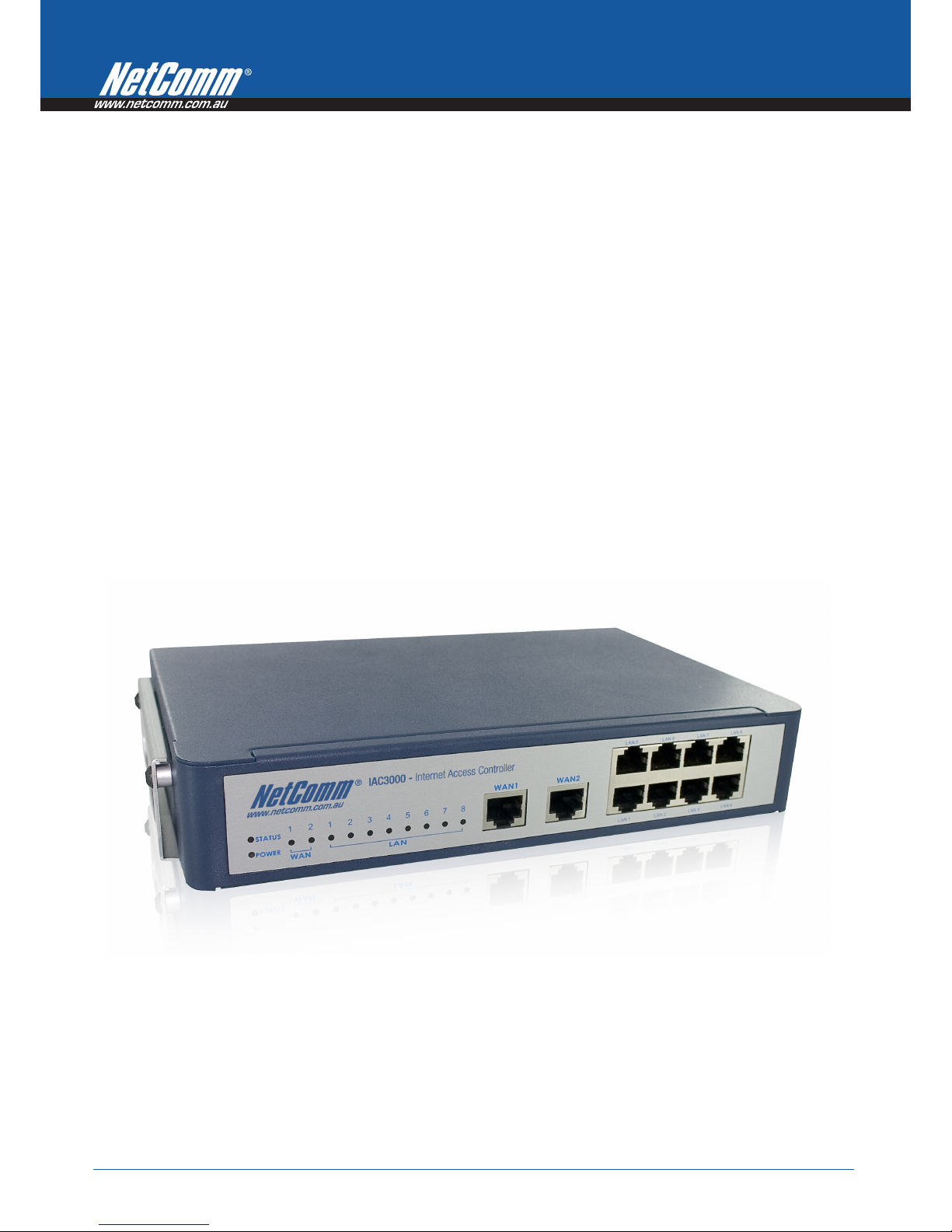
IAC3000 - Internet Access Controller
Page 2

Table of Contents
Chapter 1. Before You St art....................................................................................................................1
1.1 Purpose....................................................................................................................................................1
1.2 Document Convention............................................................................................................................1
Chapter 2. System Overview ...................................................................................................................2
2.1 Introduction of IAC3000.........................................................................................................................2
2.2 System Concept ......................................................................................................................................2
2.3 Capacity and Performance......................................................................................................................3
Chapter 3. Base Installation...................................................................................................................4
3.1 Hardware Installation..............................................................................................................................4
3.1.1 System Requirements....................................................................................................................................4
3.1.2 Package Contents..........................................................................................................................................4
3.1.3 Panel Function Descriptions .........................................................................................................................5
3.1.4 Installation Steps...........................................................................................................................................6
3.2 Software Configuration...........................................................................................................................7
3.2.1 Quick Configuration .....................................................................................................................................7
3.2.2 User Login Portal Page...............................................................................................................................18
Chapter 4. Web Interface Configuration..............................................................................................22
4.1 System Configuration ...........................................................................................................................23
4.1.1 Configuration Wizard..................................................................................................................................24
4.1.2 System Information.....................................................................................................................................25
4.1.3 WAN1 Configuration..................................................................................................................................27
4.1.4 WAN2 Configuration..................................................................................................................................29
4.1.5 WAN Traffic Settings..................................................................................................................................31
4.1.6 LAN Port Mapping.....................................................................................................................................33
4.1.7 Service Zones..............................................................................................................................................36
4.2 User Authentication ..............................................................................................................................43
4.2.1 Authentication Configuration .....................................................................................................................44
4.2.1.1 Local.......................................................................................................................................................46
4.2.1.2 POP3 ......................................................................................................................................................51
4.2.1.3 RADIUS.................................................................................................................................................52
4.2.1.4 LDAP.....................................................................................................................................................55
4.2.1.5 NT Domain.............................................................................................................................................57
4.2.1.6 ONDEMAND ........................................................................................................................................59
4.2.1.7 SIP..........................................................................................................................................................73
4.2.2 Black List Configuration.............................................................................................................................74
4.2.3 Group Configuration...................................................................................................................................76
4.2.4 Policy Configuration...................................................................................................................................80
4.2.4.1 Global Policy..........................................................................................................................................80
4.2.4.2 Policy 1~12 ............................................................................................................................................83
4.2.5 Additional Configuration............................................................................................................................87
Page 3

4.3 AP Management....................................................................................................................................90
4.3.1 AP List........................................................................................................................................................91
4.3.2 AP Discovery..............................................................................................................................................96
4.3.3 Manual Configuration...............................................................................................................................100
4.3.4 Template Settings......................................................................................................................................101
4.3.5 Firmware Management.............................................................................................................................102
4.3.6 AP Upgrade...............................................................................................................................................103
4.3.7 WDS Management....................................................................................................................................104
4.4 Network Configuration.......................................................................................................................105
4.4.1 Network Address Translation....................................................................................................................106
4.4.2 Privilege List.............................................................................................................................................108
4.4.3 Monitor IP List..........................................................................................................................................110
4.4.4 Walled Garden List / Walled Garden Ad List............................................................................................111
4.4.5 Proxy Server Properties ............................................................................................................................114
4.4.6 Dynamic DNS...........................................................................................................................................115
4.4.7 IP Mobility................................................................................................................................................116
4.4.8 VPN Configuration...................................................................................................................................117
4.5 Utilities................................................................................................................................................121
4.5.1 Change Password......................................................................................................................................122
4.5.2 Backup/Restore Setting.............................................................................................................................123
4.5.3 Firmware Upgrade....................................................................................................................................124
4.5.4 Restart.......................................................................................................................................................125
4.5.5 Network Utilities.......................................................................................................................................126
4.6 Status...................................................................................................................................................127
4.6.1 System Status............................................................................................................................................128
4.6.2 Interface Status..........................................................................................................................................130
4.6.3 Routing T able............................................................................................................................................132
4.6.4 Current Users............................................................................................................................................134
4.6.5 Traffic History...........................................................................................................................................135
4.6.6 Notification Configuration........................................................................................................................138
4.7 Help.....................................................................................................................................................140
Appendix A. Accepting Payment via Authorize.Net...........................................................................................142
Appendix B. Accepting Payment via PayPal......................................................................................................153
Page 4

Appendix C. Service Zone Deployment Example ..............................................................................................164
Appendix D. Proxy Setting..................................................................................................................................177
Appendix E. Session Limit and Session Log......................................................................................................183
Appendix F. Network Configuration on PC & User Login...............................................................................185
Appendix G. Console Interface...........................................................................................................................201
Appendix H. Local VPN......................................................................................................................................205
Appendix I. Customizable Pages.......................................................................................................................211
Appendix J. Legal & Regulatory Information..........................................................................................211
Page 5

IAC3000
User Manual
1
Chapter 1. Before You Start
1.1 Purpose
This manual is intended for the system or network administrators with the networking knowledge to complete the
step by step instructions of this manual in order to use the IAC3000 for a better management of their network
system and user data.
1.2 Document Convention
y For any caution or warning that requires special attention of readers, a highlight box with italic font is used as
below:
Warning: For security purposes, you should immediately change the Administrator’s password.
Indicates that clicking this button will return to the homepage of this section.
Indicates that clicking this button will return to the previous page.
Indicates that clicking this button will apply all of your settings.
Indicates that clicking this button will clear what you set before these settings are applied.
Page 6
IAC3000
User Manual
2
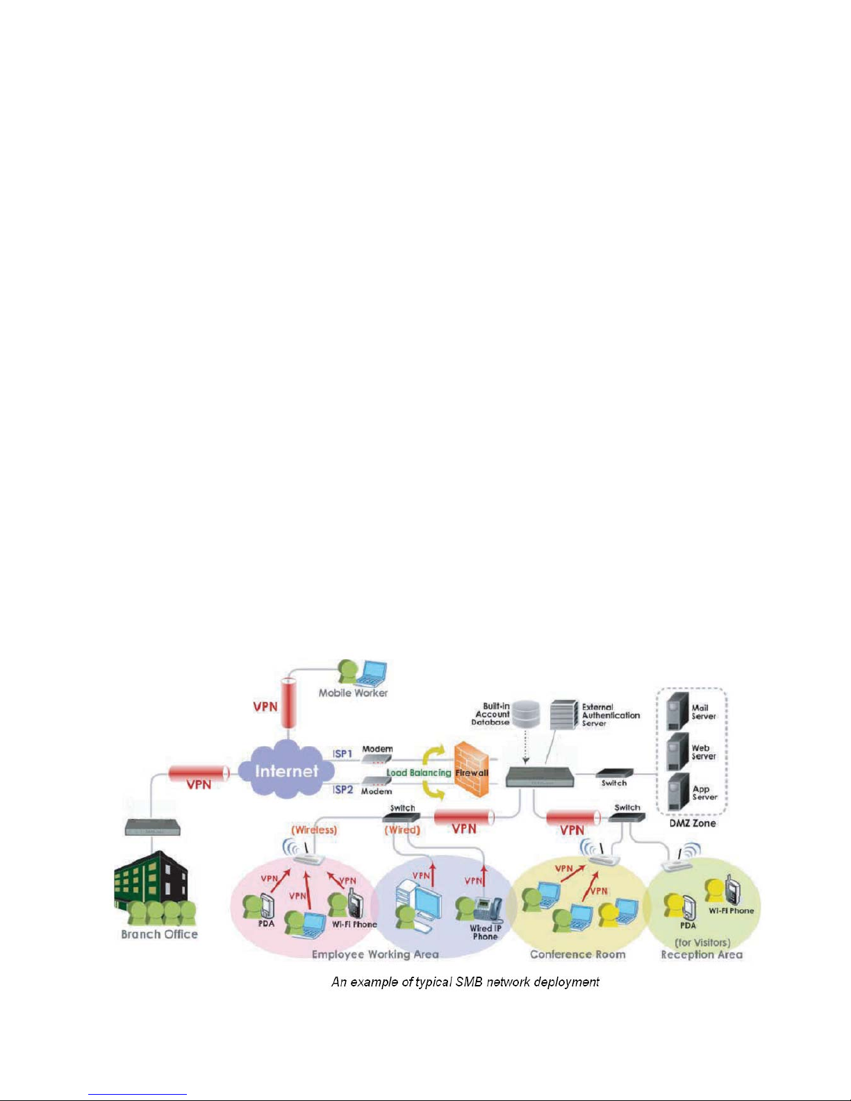
Chapter 2. System Overview
2.1 Introduction of IAC3000
IAC3000 is an Internet Access Controlle r, specially designed for wired and wireless data network environments in
small to middle scaled businesses and hotspot s. It features integrated management, secured data transmission,
and enhanced accounting and billing. System administrators can effectively monitor wired or wireless users,
including employees and guest users via its user management interface. Moreover, administrators can discover,
configure, monitor, and upg rade all managed Access Points (APs) from a single, centralized AP management
interface, the IAC3000.
2.2 System Concept
IAC3000 is capable of managing user authentication, authorization and accounting. The user account information is
stored in the local database or a specified external database server. Featured with user authentication and
integrated with external payment gateway, IAC3000 allows users to easily pay the fee and enjoy the Internet
service using credit cards through Authorize.net, PayPal & Secure Pay. With centralized AP management feature,
the administrator does not need to worry about how to manage multiple wireless access point device s. Furtherm ore,
IAC3000 introduces the concept of Service Zones - multiple virtual networks, each with its own definable network
policy. This is very useful for hotspot owners seeking to provide different customers or staff with different levels of
network services. The following diagram is an example of IAC3000 set to manage the Internet and network access
services at a hotspot venue.
Page 7

IAC3000
User Manual
3
2.3 Capacity and Performance
Capacity and Performance IAC3000
Concurrent Users 120
Local Accounts 1000
On-demand user Accounts 2,000
Managed Access Points
(NP725)
12
Monitored 3rd-Party Access Points 40
VPN Termination Tunnels 120
VPN 3DES/DES Throughput 30 Mbps
Page 8

IAC3000
User Manual
4
Chapter 3. Base Installation
3.1 Hardware Installation
3.1.1 System Requirements
¾ Standa rd 10/100BaseT network cables with RJ-45 connectors
¾ All PCs need to install the TCP/IP network proto col
3.1.2 Package Contents
The standard package of IAC3000 includes:
y IAC3000 x 1
y CD-ROM (with User Manual) x 1
y DC 12V Power Adapter x 1
y Ethernet Cable x 1
y Console Cabl e x 1
Warning: It is highly recommended to use all the supplies in the package instead of substituting any components
by other suppliers to guarantee best performance.
Page 9

IAC3000
User Manual
5
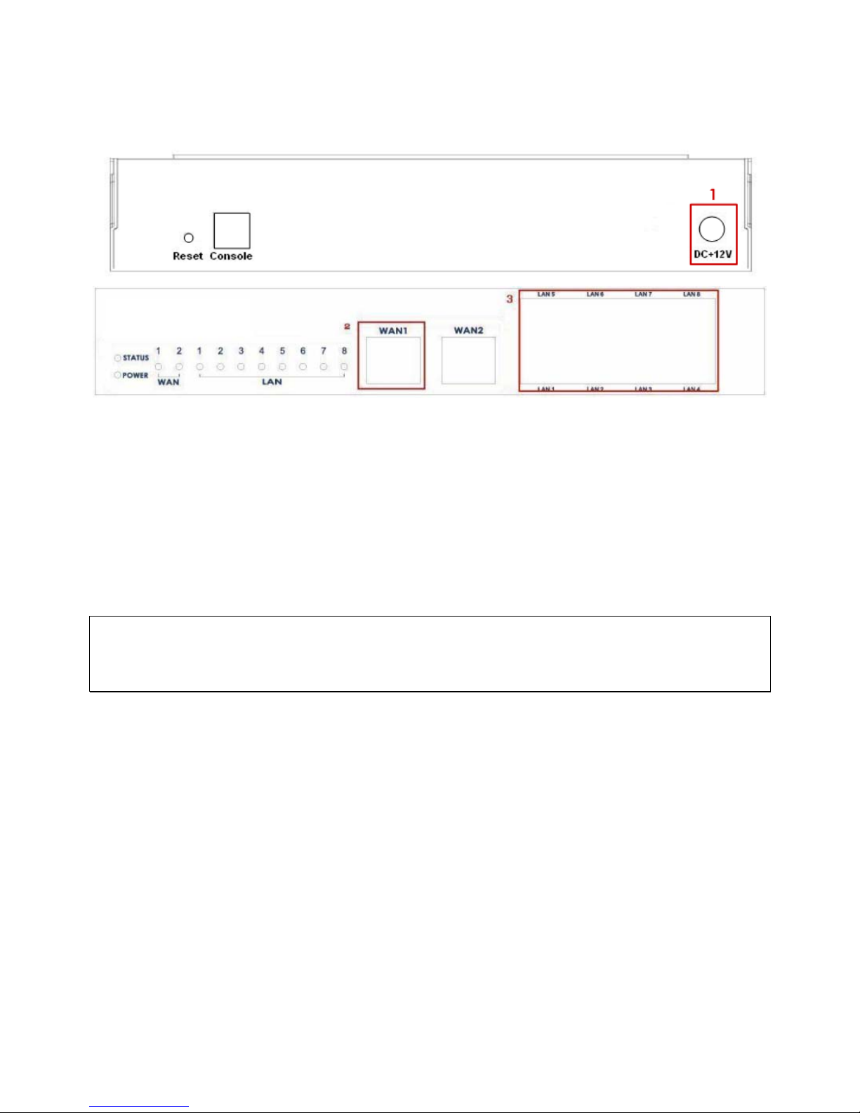
3.1.3 Panel Function Descriptions
Front Panel
LED: There are four kinds of LED, Power, Status, WAN and LAN, to indicate different status of the system.
¾ Power: LED ON indicates power on.
¾ Status: While system power is on, status OFF indicates BIOS is running; BLINKING indicates the OS is
running, and ON indicates system is ready.
¾ WAN: LED ON indicates connection to the WAN port.
¾ LAN: LED ON indicates connection to the LAN port.
WAN1/WAN2: Two WAN ports (10 Base-T / 100Base-TX RJ-45) are available on the system.
LAN1~LAN8: Client machines connect to IAC3000 via LAN ports (10 Base-T / 100Base-TX RJ-45).
Note: By Default, all LAN ports are set with Port-based Default Service Zone; for Service Zone configuratio n,
please refer to section 4.1.7.
Rear Panel
Reset: Press this button to restart the system.
Console: The system can be configured via a serial console port. The administrator can use a terminal
emulation program such as Microsoft’s HyperTerminal to login to the configuration console interface to change
admin password or monitor system status, etc.
DC+12V: The power adapter attaches here.
Page 10
IAC3000
User Manual
6
3.1.4 Installation Steps
Steps to install IAC3000:
1. Connect the 12V power adapter to the power socket on the rear panel. The Power LED should be on to
indicate a proper connection.
2. Connect an Ethernet cable to the WAN1 Port on the front panel. Connect the other end of the Ethernet cable to
an ADSL modem, a cable modem or a switch/hub of the network. The LED of WAN1 port should be on to
indicate a proper connection.
3. Connect an Ethernet cable to one of the LAN1~LAN8 Ports on the front panel. Connect the other end of the
Ethernet cable to an administrator’s PC or a client PC, AP, or switch in managed network. The LED of the
connected port should be on to indicate a proper connection.
Attention:
IAC3000 supports Auto Sensing MDI/MDIX. You may use either straight through or cross-over cable to conn ect the
Ethernet Port.
Page 11
3.2 Software Configuration
3.2.1 Quick Configuration
IAC3000 supports web-based configuration. Upon the completion of hardware installation, IAC3000 can be
configured via web browsers with JavaScript enabled such as Internet Explorer version 6.0 and above or Firefox.
There are two ways to configure the IAC3000 system: using the online Configuration Wizard or changing the
settings by commands manually. The Configuration Wizard comprises of six basic steps as follows. Follow the
instructions of Configuration Wizard to enter the required information step by step, save your settings, and restart
IAC3000. The 6 steps of Configuration Wizard are listed below:
Step 1. Change Admin’s Password
Step 2. Choose System’s Time Zone
Step 3. Set System Information
Step 4. Select Connection Type for WAN Port
Step 5. Add Local User Account (Optional)
Step 6. Save and Restart IAC
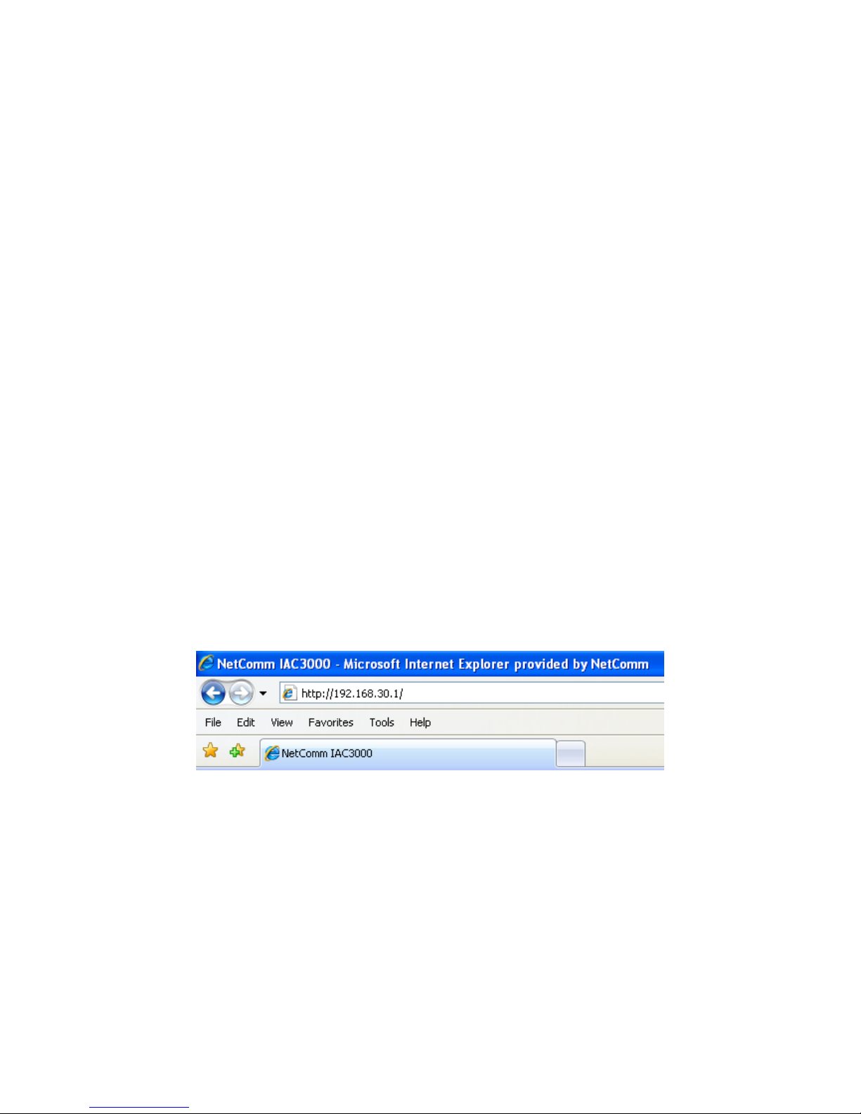
Please follow the following steps to complete the quick configuration:
1. To access the web man agement interface, connect a PC to one of the LAN1~8 ports, and then launch a
browse. Make sure you have set DHCP in TCP/IP of your PC to get an IP address dynamically.
Next, enter the gateway IP address of IAC3000 at the address field. The default gateway IP address
is“http://192.168.30.1” (“https” is also supporte d in IAC3000, it is used for a secured connection).
The administrator login page will appear . Enter “admin”, the default username, and “admin”, the default
password, in the User Name and Password fields. Click Enter to log in.
Page 12

IAC3000
User Manual
8
After a successful login, a “Welcome to System Administration” page will appear on the screen.
If ‘https’ is used instead of ‘http’ for accessing the IAC3000 web management interface, by default, the IAC3000 is
not using a trusted SSL certificate (for more information, please see 4.2.5 Additional Configuration), there will be
a “Certificate Error”, because the browser treats IAC3000 as an illegal website. Please press “Continue to this
website” to continue. The default user login page will then appear in the browser.
Caution: If you can’t get the login screen, the reasons may be:
(1) The PC is set incorrectly so that the PC can’t obtain the IP address automatically from the LAN port;
(2) The IP address and the default gateway are not under the same network segment. Please use default IP
address such as 192.168.30.xx in your network and then try it again. For the configuration on PC, please refer to
Appendix F.
Page 13
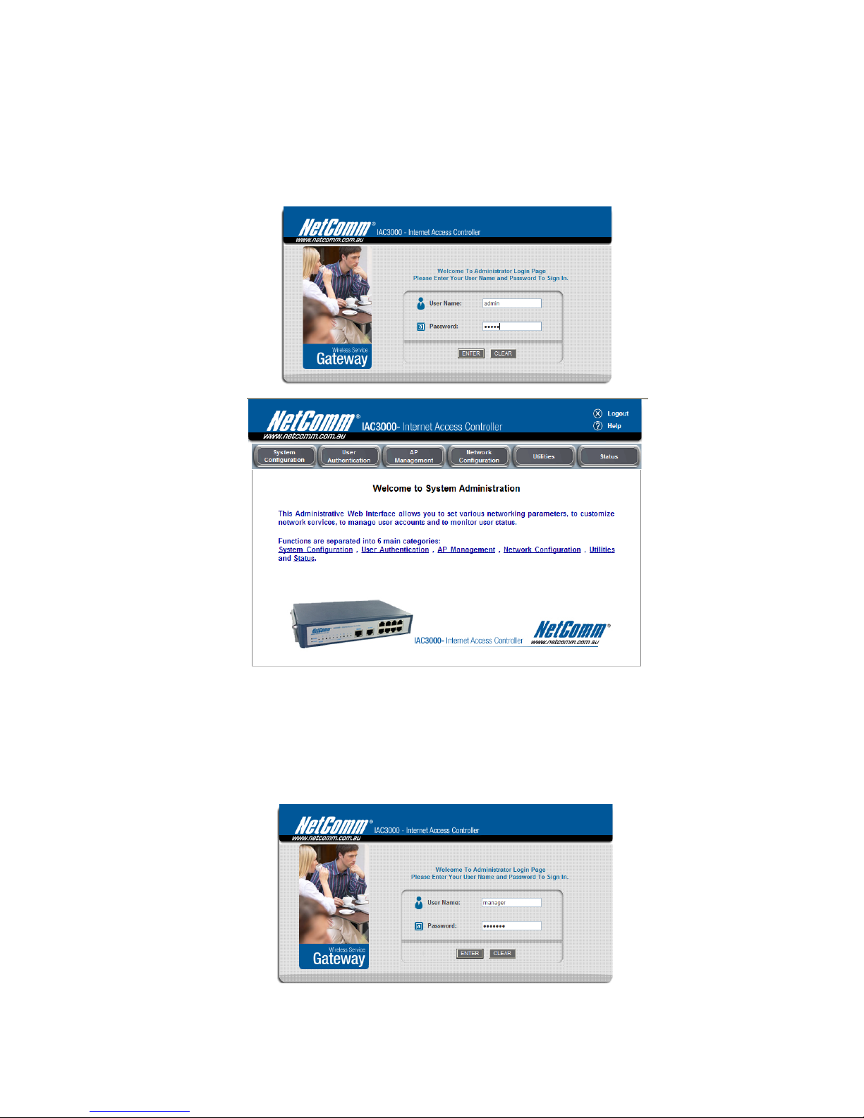
IAC3000 supports three kinds of account interface. You can log in as admin, manager or operator. The default
username and password as follows.
Admin: The administrator can access all area of the IAC3000.
User Name: admin
Password: admin
Manager: The manager can access the area under User Authentication to manage the user account, but no
permission to change the settings of the profiles of Firewall, Specific Ro ute and Schedule.
User Name: manager
Password: manager
Page 14
IAC3000
User Manual
10
Operator: The operator can only access the area of Create On-demand User to create and print out the new on-
demand user accounts.
User Name: operator
Password: operator
Page 15
IAC3000
User Manual
11
After a successful login to IAC3000, a web management interface with a welcome message will appear.
Note: To logout, simply click the Logout icon on the upper right corner of the interface to return to the login screen.
2. Now you are ready to run the Wizard.
To quickly configure IAC3000 by using the Configuration Wizard, click System Configuration from the top
menu to go to the System Configuration page. Then , click Con figuration Wizard on the left.
Click the Run Wizard button to begin the Configuration Wizard. The Configuration Wizard will appear in a
pop-up browser window . Click Next to begin.
3. Running Configuration Wizard
A welcome screen that briefly introduces the 6 steps will appear. Click Next to begin.
Note: During every step of the wizard, if you wish to go back to modify the settings, please click the Back
button to go back to the previous step.
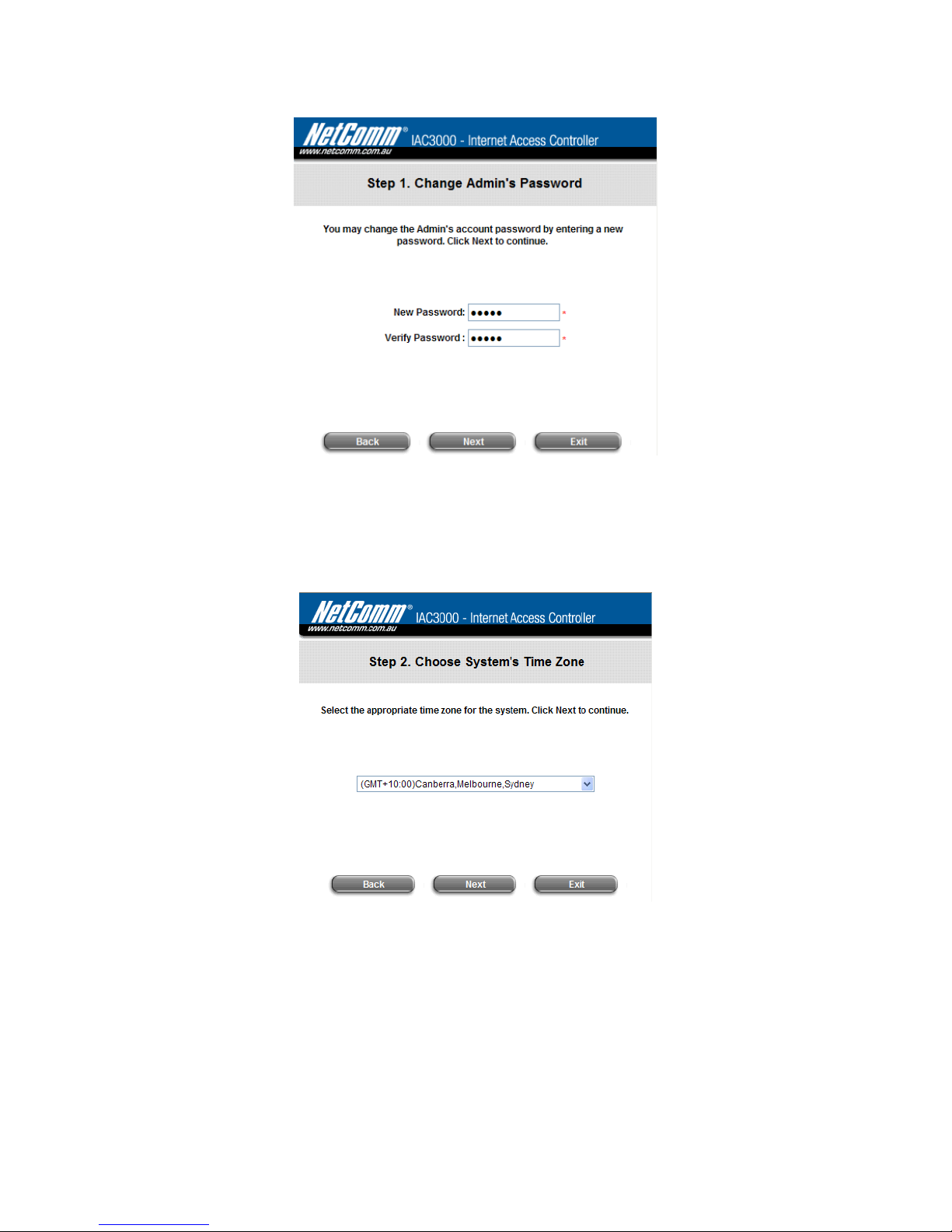
y Step 1. Change Admin’s Password
h Enter a New Password for the admin account and retype it in the Verify Password field (20-
character maximum and no spaces).
Page 16
IAC3000
User Manual
12
h Click Next to continue.
y Step 2. Choose System’s Time Zone
h Select a proper time zone from the drop-down list box.
h Click Next to continue.
Page 17
IAC3000
User Manual
13
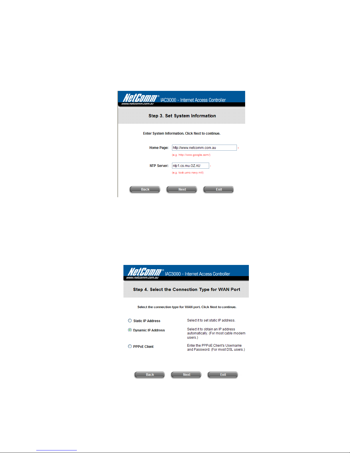
y Step 3. Set System Information
h Home Page: Enter the URL that users should be initially directed to when successfully
authenticated to the network.
h NTP Server: Enter the URL of the external time server for IAC3000 time synchronization or use the
default setting.
h Click Next to continue.
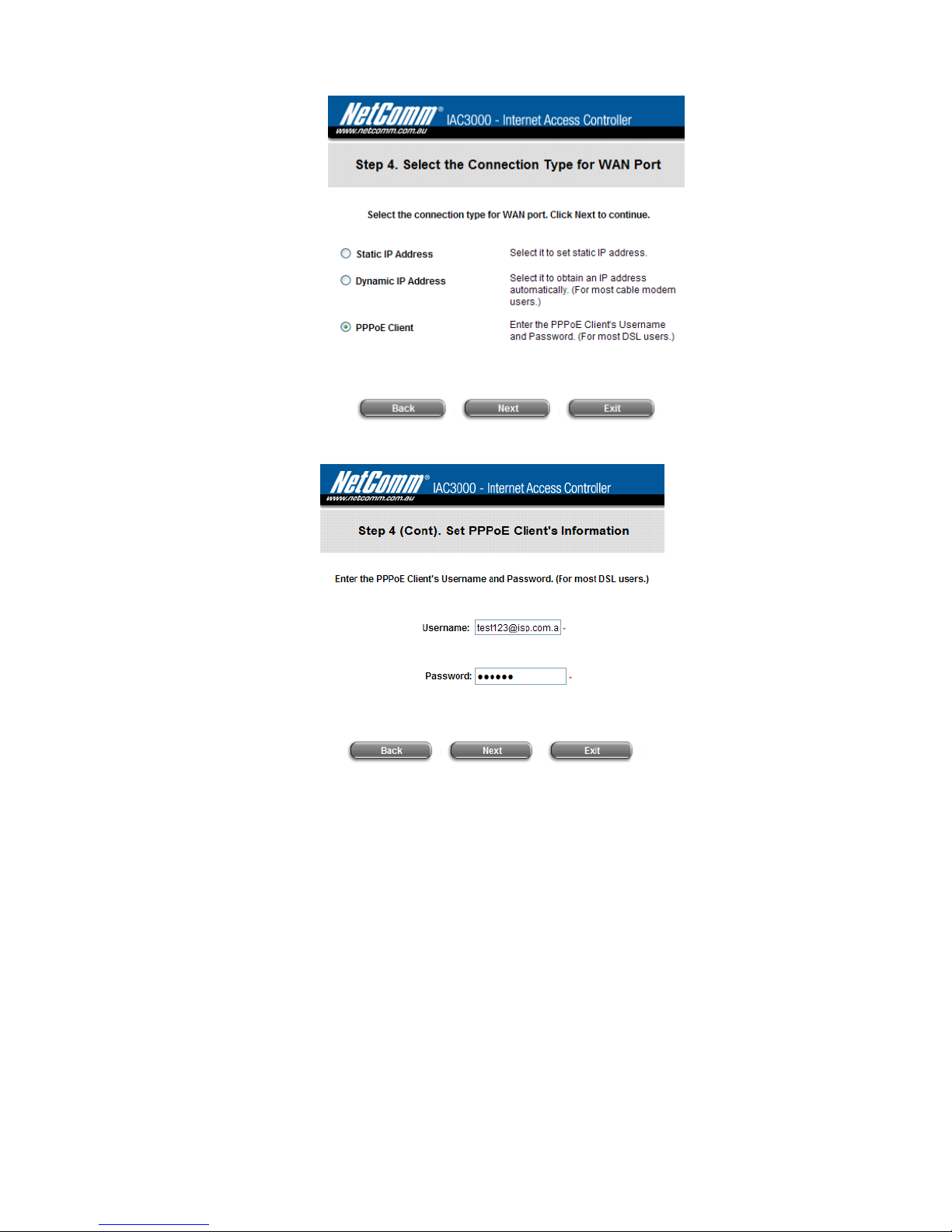
y Step 4. Select Connection Type for WAN Port
Three are three types of WAN port to be selected from: Static IP Address, Dynamic IP Address and
PPPoE Client. Select a proper Internet connection type and click Next to continue.
¾ Dynamic IP Address
If this option is selected, an appropriate IP address and related information will automatically be
assigned.
Click Next to continue.
¾ Static IP Address: Set WAN Port’s Static IP Address
Page 18
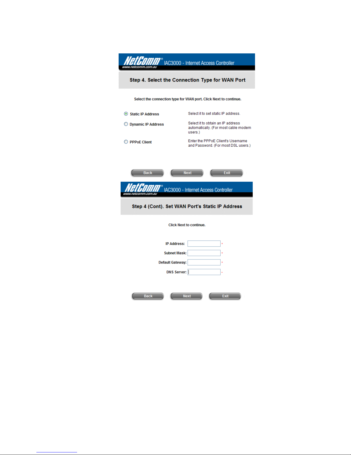
IAC3000
User Manual
14
Enter the “IP Address”, “Subnet Mask” and “Default Gateway” “DNS Server” provided by your ISP.
Click Next to continue.
¾ PPPoE Client: Set PPPoE Client’s Information
Enter the “Username” and “Password” provided by the ISP.
Click Next to continue.
Page 19
IAC3000
User Manual
15
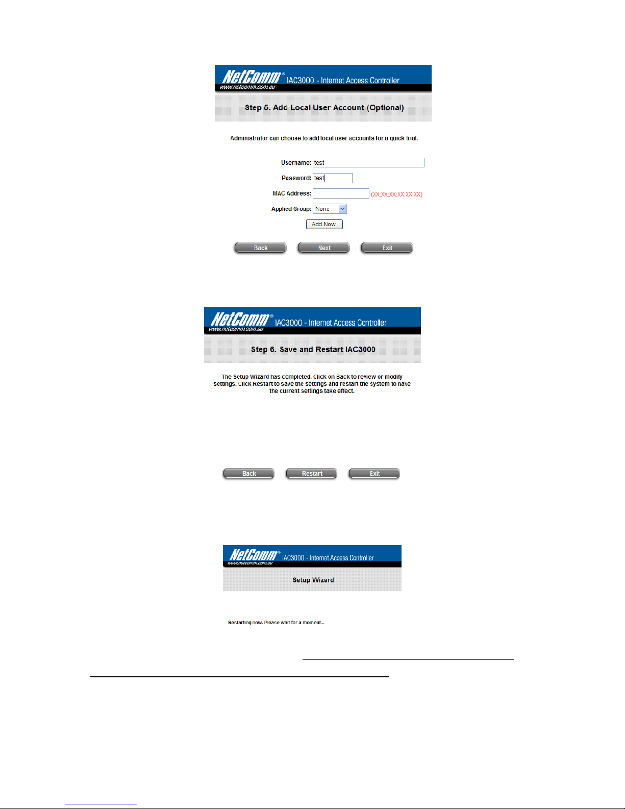
y Step 5. Add Local User Account (Optional)
¾ A new user can be added to the Local User datab ase. To add a user here, enter the Username (e.g.
test), Password (e.g. test), MAC Address (optional, to specify the valid MAC address of this user)
and assign an Applied Group to this particular user (or use the default None).
¾ More users can be added by clicking the Add Now button.
¾ Click Next to continue.
Page 20
IAC3000
User Manual
16
y Step 6. Save and Restart IAC
¾ Click Restart to save current settings and restart IAC3000. The Setup Wizard is now complete.
y Restart: When IAC3000 is restarting, a “Restarting now. Please wait for a moment.” message will
appear on the screen.
Please do NOT interrupt IAC3000 restart process until the Configuration Wizard pop-up window has
disappeared—which indicates the restart proce ss has been completed. If all steps are done properly, you can
start working on the system or refer to the User Manual for advanced settings.
Page 21
IAC3000
User Manual
17
Note: For an example of user login, please refer to Appendix F. Network Configuration on PC & User Login.
Page 22
IAC3000
User Manual
18
3.2.2 User Login Portal Page
To login from the login portal page via the controlled port, the user has to be authenticated by the system with
username and password. The administrator also can verify if the configuration o f IAC3000 has been done properly.
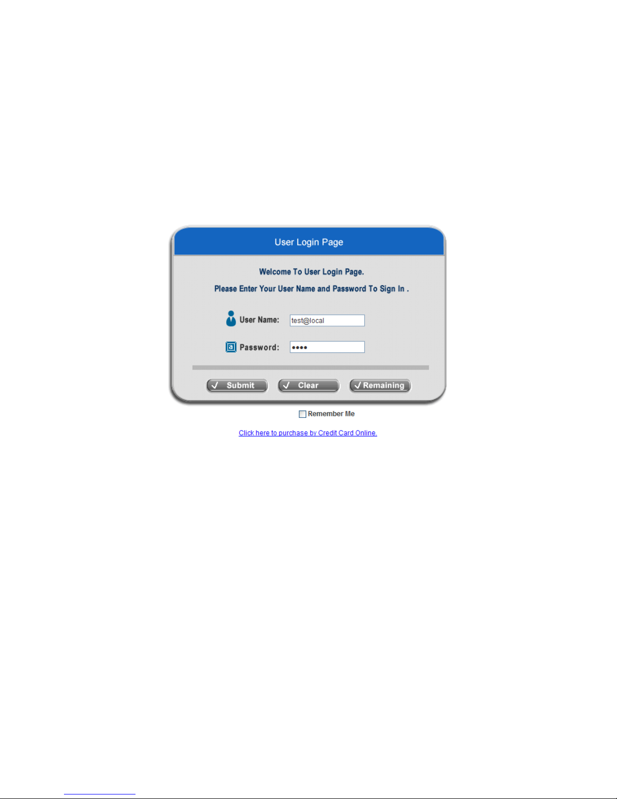
1. First, provided the steps in 3.1.4 and the quick set up wizard were completed, you may now connect a client’s
device (for example, a PC) to the controlled port of IAC3000, and set the device to obtain an IP address
automatically. After the client obtains the IP address, open an Internet browser. Try to launch any website and
then the default User Login Page will appear . Enter a valid User Name and Password (e.g. test@local for
the username and test for the password). Click Submit button.
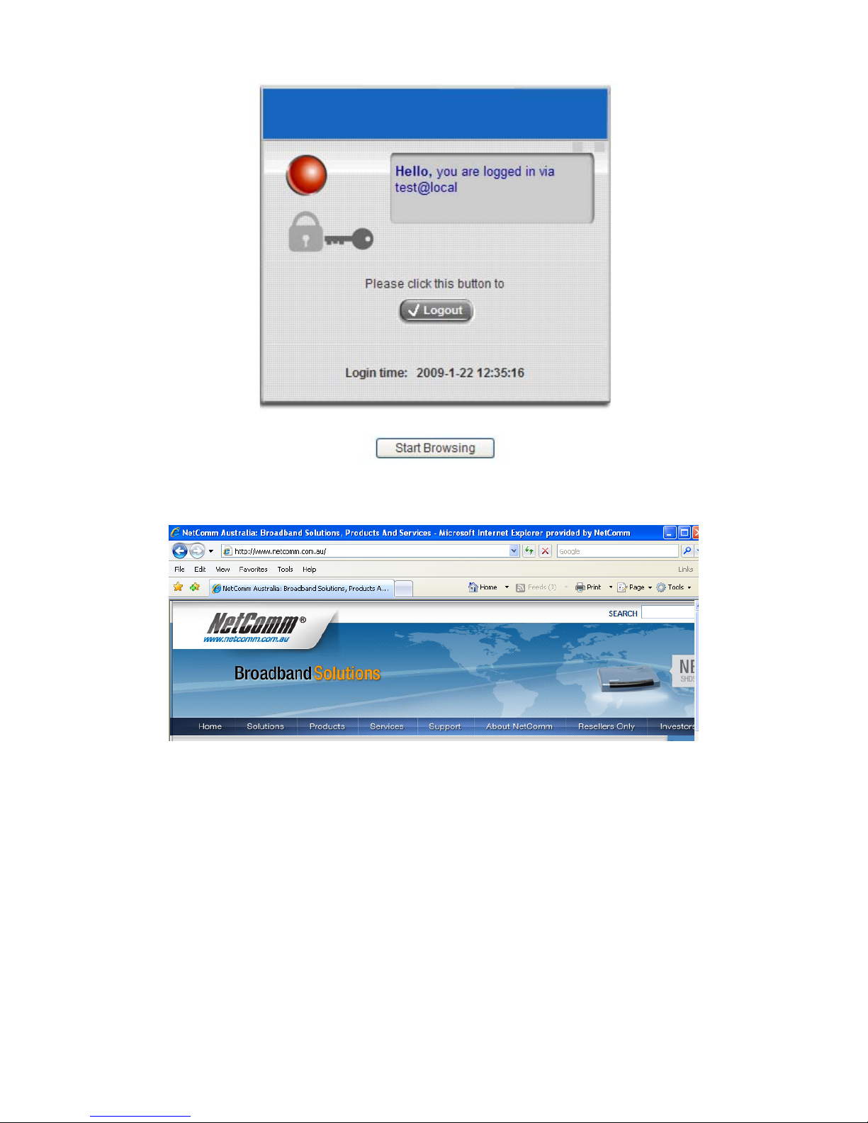
2. Login success page will appear if IAC3000 has been installed and configured successfully. Now, clients can
access the network or surf on the Internet.
Page 23
IAC3000
User Manual
19
Page 24
IAC3000
User Manual
20
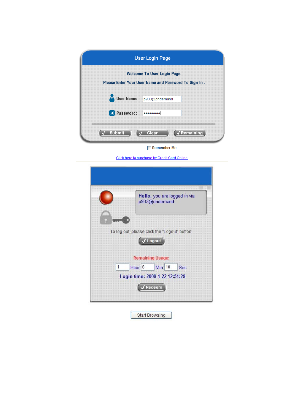
3. When an on-demand user login successfully, the following Login Success page will appear. There is extra
information showing “Remaining usage” and a “Redeem” button on the bottom.
y Remaining usage: Show the remaining quota that the on-demand user can use to surf Internet.
Page 25
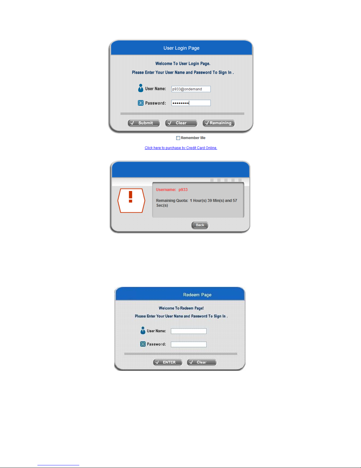
IAC3000
User Manual
21
y Redeem: When the remaining credit is going to use up, the client has to pay for adding credit to the
counter, and then, the client will get a new username and password. After clicking the Redeem button,
a Redeem Page will appear. Please enter the new username and password obtained and click Enter
button. The total available time or data size will be shown u p after adding credit.
Page 26

IAC3000
User Manual
22
Chapter 4. Web Interface Configuration
This chapter will guide you through further detailed settings. The following table is the UI and functions of the
IAC3000.
OPTION
System
Configuration
User
Authentication
AP
Management
Network
Configuration
Utilities Status
Configuration
Wizard
Authentication
Configuration
AP List
Network
Address
Translation
Change
Password
System
Status
System
Information
Black List
Configuration
AP Discovery Privilege List
Backup/Restore
Settings
Interface
Status
WAN1
Configuration
Group
Configuration
Manual
Configuration
Monitor IP List
Firmware
Upgrade
Routing
Table
WAN2
Configuration
Policy
Configuration
Template
Settings
Walled Garden
List
Walled Garden
Ad List
Restart
Current
Users
WAN Traffic
Settings
Additional
Configuration
Firmware
Management
Proxy Server
Properties
Network
Utilities
Traffic
History
LAN Port
Mapping
AP Upgrade Dynamic DNS
Notification
Configuration
Service Zones
WDS
Management
IP Mobility
FUNCTION
VPN
Configuration
Caution: After finishing the configuration of the settings, please click Apply and pay attention to see if a restart
message appears on the screen. If such message appears, system must be restarted to allo w the settings to take
effect. All on-line users will be disconnected during restart.
Page 27
IAC3000
User Manual
23
4.1 System Configuration
This section includes the following functions: Configuration Wizard, System Information, WAN1 Configuration,
WAN2 Configuration, WAN Traffic Settings, LAN Port Mapping and Service Zones.
Page 28

IAC3000
User Manual
24
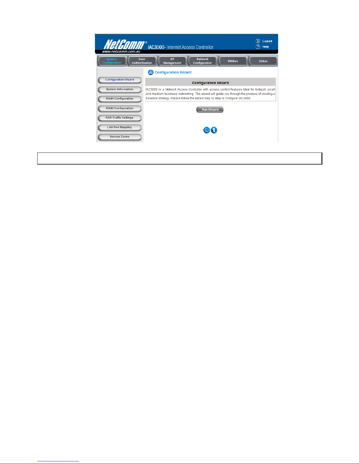
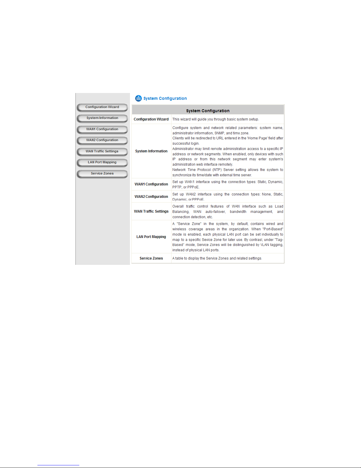
4.1.1 Configuration Wizard
There are two ways to configure the IAC3000 system: using the online Configuration Wizard or changing the
settings by commands manually. The Configuration Wizard comprises of 6 basic steps, providing a simple and
easy way to go through the basic setups of IAC3000 (Refer to section 3.2).
Page 29
IAC3000
User Manual
25
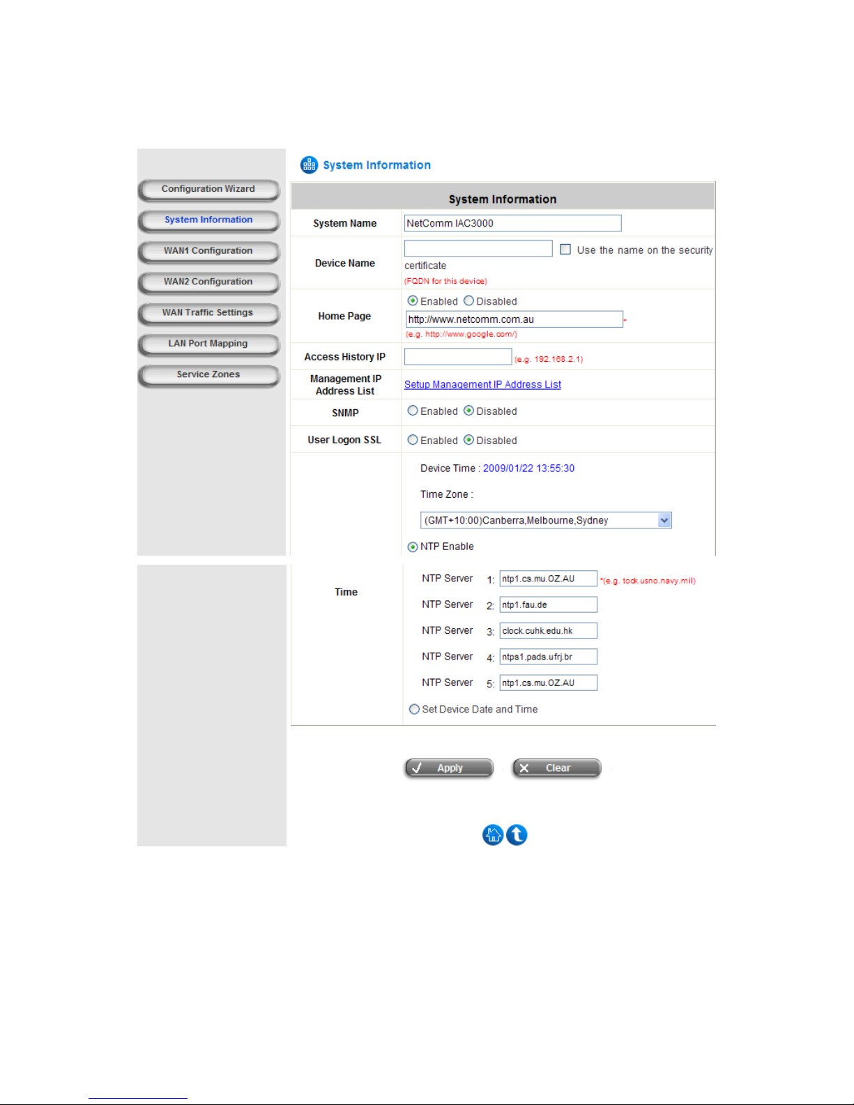
4.1.2 System Information
Main information about IAC3000 is shown as follows:
y System Name: Set the system’s name or use the default name.
y Device Name: FQDN (Fully-Qualified Domain Name). This is the domain name of the IAC3000 as seen on
client machines connected on LAN ports. A user on client machine can use this domain name to access
IAC3000 instead of its IP address. In addition, when “Use the name on the sec urity certificate” option is
checked, the system will use the CN (Common Name) value of the uploaded SSL certificate as the domain
name.
Page 30
IAC3000
User Manual
26
y Home Page: Enter the website of a Web Server to be the homepage. When users log in successfully, they will
be directed to the homepage set. Usually, the homepage is set to the company’s website, such as
http://www.netcomm.com.au. If the home page function is disabled, the user will be directed to the URL she/he
tries to visit originally.
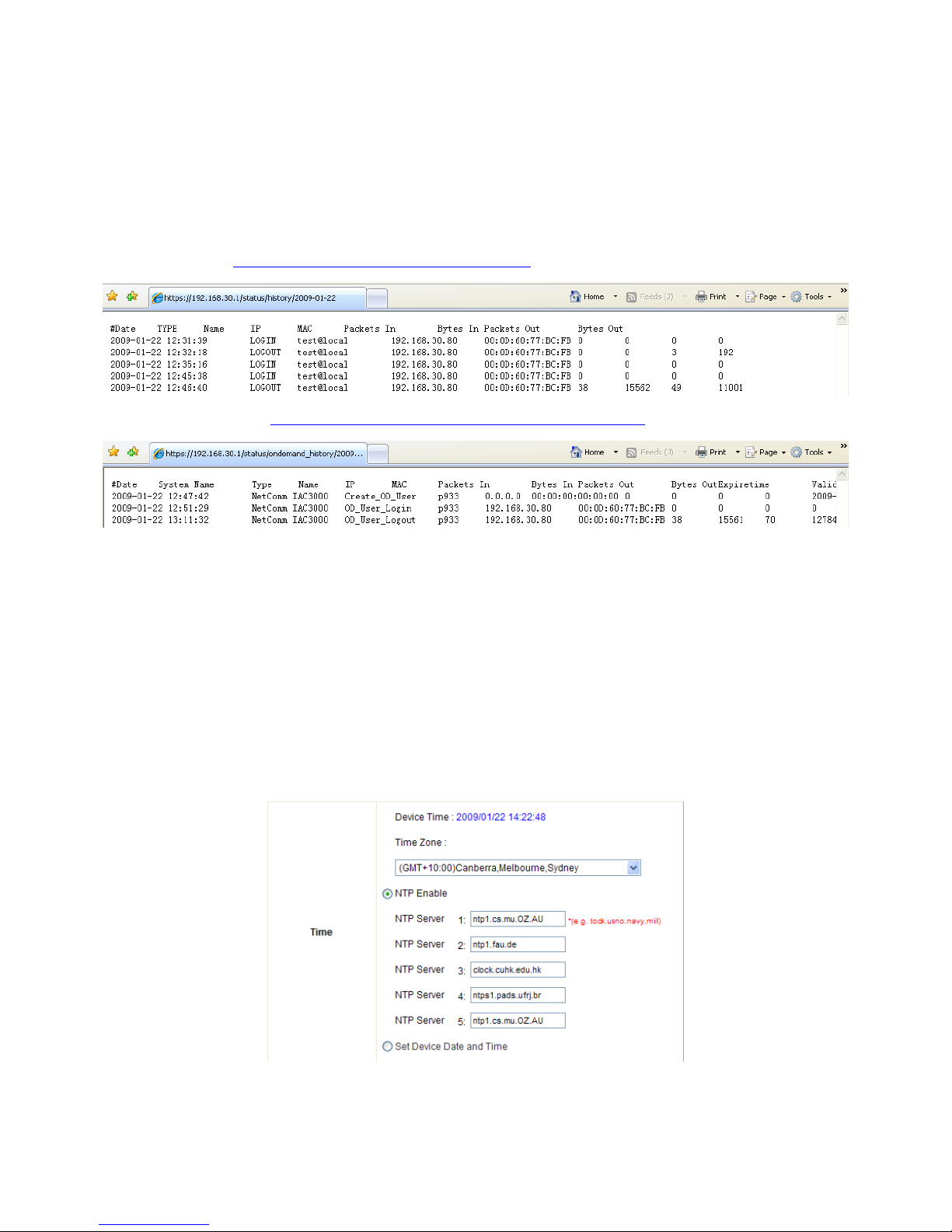
y Access History IP: Specify an IP address of the administrator’s computer or a billing system to get billing
history information of IAC3000 with the predefined URLs as the following:
Traffic Hist ory :
https://192.168.30.1/status/history/2009-01-22
On-demand History:
https://192.168.30.1/status/ondemand_history/2009-01-22
y Management IP Address List: In the page of "Management IP Address List", the administrator can grant the
access of the web management interface by specifying a list specific IP addresse s or ranges of IP addresses,
no matter the access is from WAN or LAN.
y SNMP: If the function is enabled, the Manager IP and the community can be assigned to access the
management information base (MIB) of the system.
User Logon SSL: Enable to activate https (encryption) or disable to activate http (non encryption) login pa ge.
y Time: IAC3000 supports NTP (Network Time Protocol) communication protocol to synchronize the network
time. Please specify the IP address of a NTP server to adjust the time automatic ally (Universal Time is
Greenwich Mean Ti me, GMT). The time can also be set manually by selecting “Set Device Date and Time”
and then entering the date and time in these fields.
Page 31

IAC3000
User Manual
27
4.1.3 WAN1 Configuration
There are 4 methods of obtaining IP address for the WAN Port: Static IP Address, Dynamic IP Address, PPPoE
and PPTP Client.
y Static IP Address: Manually specifying the IP address of the WAN port. The red asterisks indicate required
fields to be filled in.
IP address: the IP address of the WAN1 port.
Subnet mask: the subnet mask of the network WAN1 port co nnects to.
Default gateway: a gateway of the network WAN1 port connects to.
Preferred DNS Server: The primary DNS server is used by the system.
Alternate DNS Server: The substitute DNS server is used by the system. This is an optional field.
y Dynamic IP Address: It is only applicable for the network environment where the DHCP server is available on
the network. Click the Renew button to get an IP address automatically.
Page 32

IAC3000
User Manual
28
y PPPoE Client: When selecting PPPoE to connect to the network, please set the “Username”, “Password”,
“MTU” and “CLAMPMSS”. There is a Dial on demand function under PPPoE. If this function is enabled, a
Maximum Idle Time can be set. When the idle time is reached, the system will automatically disconnect itself.
y PPTP Client: Select STATIC to specify the IP address of the PPTP Client manually or select DHCP to get the
IP address automatically. The fields with red asterisks are required to be filled in. There is a Dial on demand
function under PPTP. If this function is enabled, a Maximum Idle Time can be set. When the idle time is
reached, the system will automatically disconnect itself.
Page 33

IAC3000
User Manual
29
4.1.4 WAN2 Configuration
Select None to disable this WAN2 interface, or there are 3 connection types for the WAN2 port: Static IP Address,
Dynamic IP Address, and PPPoE Client.
y None: The WAN2 Port is disabled.
y Static IP Address: Manually specifying the IP address of the WAN port. The red asterisks indicate required
fields to be filled in.
IP Address: the IP address of the WAN2 port.
Subnet Mask: the subnet mask of the network WAN2 port connects to.
Default Gateway: a gateway of the network WAN2 port connects to.
Preferred DNS Server: The primary DNS server is used by the system.
Alternate DNS Server: The substitute DNS server is used by the system. This is an optional field.
y Dynamic IP Address: It is only applicable for the network environment where a DHCP server is available.
Click the Renew button to get an IP address.
Page 34

IAC3000
User Manual
30
y PPPoE Client: When selecting PPPoE to connect to the network, please set the “UserName” and
“Password”. There is a Dial on demand function under PPPoE. If this function is enabled, Maximum Idle
Time can be set. When the idle time is reached, the system will automatically disconnect itself.
Page 35

IAC3000
User Manual
31
4.1.5 WAN Traffic Settings
The section is for administrators to configure the control over the entire system’s traffic though the WAN interface
(WAN1 and WAN2 ports).
Available Bandwidth on WAN Interface:
y Uplink: It specifies the maximum uplink bandwidth that can be shared by clients of the system.
y Downlink: It specifies the maximum downlink bandwidth that can be shared by clients of the system.
Connection Detection & WAN Failover:
y Target for detecting Internet connection: These URLs are used by the system as the targets to detect
Internet connection, for alerting Internet disconnection and WAN Failover. At least one URL is required to
enable WAN Failover.
y Enable Load Balancing: Outbound load balancing is supported by the system. When enabled, the system will
allocate traffic between WAN1 and WAN2 dynamically according to designed algorithms based on the weight
ratio.
¾ WAN1 Weight: The percentage of traffic through WAN1. (Range: 1~99; by default, it is 50)
¾ Base: The weight ratio between WAN1 and WAN2 can be based on Sessions, Packets or Bytes. Packets
and Bytes are based on historic data. New connection sessions will be distributed between WAN1 and
WAN2 by a weight ratio using random number.
y Enable WAN Failover: Normally a Service Zone uses WAN1 as it primary WAN interface. When enabled and
WAN2 is available, WAN1's traffic will be routed to WAN2 when WAN1 connection is down. On the other hand,
a Service Zone’s policy could also use WAN2 as its interface; in that case, if WAN2 is down, the WAN2's traffic
under its policy will also be routed to W A N1.
¾ Fall back to WAN1 when WAN1 is available again: If WAN Failover is enabled, the traffic will be routed to
WAN2 automatically when WAN1 connection fails. When fall back to WAN1 is enabled, the routed traffic
will be connected back to WAN1 when WAN1 connection is recovered.
Page 36

IAC3000
User Manual
32
y Warning of Internet Disconnection: When enabled, there is a text box available for the administrator to enter
a reminding message. This reminding message will appear on clients' screens when Internet connection is
down. An example of the reminding message can be “Sorry! The service is temporarily unavailable.”
Note: SIP authentication is exempt from Load Balancing and WAN Failover. A fixed WAN port is
used for SIP traffic.
Page 37

IAC3000
User Manual
33
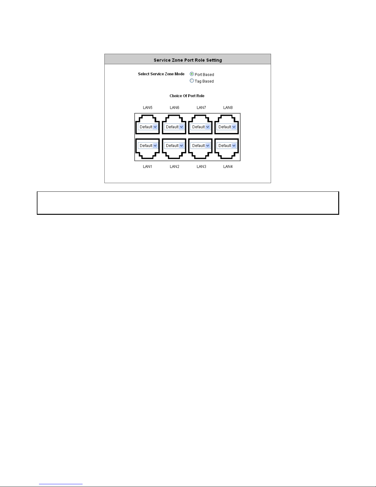
4.1.6 LAN Port Mapping
IAC3000 supports multiple Service Zones in either of the two VLAN modes, Port-Based or Tag-Based, but not
concurrently. In Port-Base mode, each LAN port can only serve traffic from one Service Zone as each Service
Zone is identified by physical LAN ports. In Tag-Based mode, each LAN port can serve traffic from any Service
Zone as each Service Zone is identified by VLAN tags carried within message frames. By default, the system is
in Port-Based mode with Default Service Zone enabled and all LAN ports are mapped to Default Service
Zone. Compare the two figures below to see the differences.
It is recommended that the administrator decides which mode is better for a multiple-service-zone deployment
before proceeding further with the system configuration. Settings for the two VLAN modes are slightly different, for
example, the VLAN Tag setting is required for Tag-Based mode.
Page 38
IAC3000
User Manual
34
y Select Service Zone Mode: Select a VLAN mode, either Port-Based or Tag-Based.
Note: The switches deployed under IAC3000 in Port-Based mode must be Layer 2 switches only.
The switch deployed under IAC3000 in Tag-Based mode must be a VLAN switch only.
¾ Port-Based: When Port-Based mode is selected; traffic from different virtual Service Zones will be
distinguished by physical LAN ports. Each LAN port can be mapped to a Service Zone in the form of a
many-to-one mapping between ports and Service Zones.
o Specify a desired Service Zone for each LAN Port: For each LAN port, select a Service Zone to
which the LAN port is to be mapped from the drop-down list box.
By factory default, all LAN ports are mapped to Default Service Zone; therefore, the administrator can
enter the web management interface via any LAN port upon the first power up of the system. From the
drop-down list box, all disabled Service Zones are gray-out; to activate any desired Service Zone,
please configure the desired Service Zone under the Service Zone tab and enable its Service Zone
Status (refer to Section 4.1.7. Service Zones).
Page 39

IAC3000
User Manual
35
¾ Tag-Based: When the Tag-Based mode is selected, traffic from different virtual Service Zones will be
distinguished by VLAN tagging, instead of by physical LAN ports.
Select Tag-Based and then click Apply to activate the Tag-Based VLAN function. When a restart
message screen appears, do NOT restart the system until you have completed the configuration under
the Service Zones tab first.
Note: For more information on enabling and configuring Service Zones, please refer to Appendix C. Service Zone
Deployment Example.
Page 40

IAC3000
User Manual
36
4.1.7 Service Zones
A Service Zone is a logical network area to cover certain wired and wireless networks in an organization such as
SMB or branch offices. Service Zones can be set up as port-based or tag-based. For example, using a tag-based
method to deploy Service Zones, by associating a unique VLAN Tag and SSID with each Service Zone,
administrators can separate one physical network into different logical zones. Users attempting to access the
resources within a particular Service Zone will be controlled based on the group they belong to and the group’s
associated policy profile, such as authentication methods, security features, wireless encryption methods, traffic
control, and etc.
There are up to eight Service Zones plus one default zone to be utilized; by default, they are named as: Default,
SZ1~SZ8 , as shown in the two tables below.
Port-based Service Zone:
¾ Service Zone Name: Mnemonic name of the Service Zone.
¾ Port Map: Shows which port maps to which Service Zone in port-based mode.
Page 41

IAC3000
User Manual
37
¾ SSID: The SSID that is associated with the Service Zone.
¾ WLAN Encryption: Data encryption method for wireless networks within the Service Zone.
¾ Applied Policy: The global policy that is applied to the Service Zone. This is for users who are not
assigned to any group such as users who access the network using Walled Garden. Each group can set
its own group policy. Group policy overrides global Service Zone policy.
Tag-based Service Zone:
¾ Service Zone Name: Mnemonic name of the Service Zone.
¾ VLAN Tag: The VLAN tag number that is mapped to the Service Zone in tag-based mode.
¾ SSID: The SSID that is associated with the Service Zone.
¾ WLAN Encryption: Data encryption method for wireless networks within the Service Zone.
¾ Applied Policy: The global policy that is applied to the Service Zone. This is for users who are not
assigned to any group such as users who access the network using Walled Garden. Each group can set
its own group policy. Group policy overrides global Service Zone policy.
Note: For more information about Group, please refer to 4.2.3 Group Configuration section.
¾ Default Authentication: Default authentication method/server that is used within the Service Zone.
¾ Status: Each Service Zone can be enabled or disabled.
¾ Details: Configurable, detailed settings for each Service Zone.
Click Configure button to configure each Service Zone: Basic Settings, SIP Interface Configuration,
Authentication Settings, Wireless Settings, and Managed AP in Each Service Zone.
Page 42

IAC3000
User Manual
38
1) Service Zone Setting s – Basic Settings
¾ Service Zone Status: Each service zone can be enabled or disa bled except for the default service zone.
¾ Service Zone Name: The name of service zone could be input here.
¾ Network Settings:
o Operation Mode: Contains NAT mode and Router mode. When NAT mode is chosen, the service
zone runs in NAT mode. When Router mode is chosen this service zone runs in Router mode.
o IP address: The IP Address of this service zone.
o Subnet Mask: The subnet Mask of this service zone.
¾ DHCP Server Settings: Related information needed on setting up the DHCP Server is listed here. Please
note that when “Enable DHCP Relay” is enabled, the IP address of clients will be assigned by an external
DHCP server . The system will only relay DHCP information from the external DHCP server to downstream
clients of this service zone.
o Start IP Address / End IP Address: A range of IP addresses that built-in DHCP server will assign
to clients. Note: please change the Management IP Address List accordingly (at System
Configuration >> System Information >> Management IP Address List) to permit the administrator
to access the IAC3000 admin page after the default IP address of the network interface is changed.
o Preferred DNS Server: The primary DNS server that is used by this Service Zone.
o Alternate DNS Server: The substitute DNS server that is used by this Service Zone.
o Domain Name: Enter the domain name for this service zone.
o WINS Server IP: The IP addre ss of the WINS (Windows Internet Naming Service) server that if
Page 43

IAC3000
User Manual
39
WINS server is applicable to this service zone.
o Lease Time: This is the time peri od that the IP addresses issued from the DHCP server are valid
and available.
o Reserved IP Address List: Each service zone can reserve up to 40 IP addresses from predefined
DHCP range to prevent the system from issuing these IP addre sses to downstream clients. The
administrator can reserve a specific IP address for a special device with certain MAC address.
2) Service Zone Setting s – SIP Interface Configuration
The system provides SIP proxy functionality, which allows SIP clients to pass through NAT. When enabled, all
SIP traffic can pass throug h NAT via a fixed W A N interface. The policy route setting of SIP Authentication must
be configured carefully because it must cooperate with the fixed WAN interface for SIP authentication.
SIP Transparent Proxy can be activated in both NAT and Router mode. SIP Authentication must support in
either mode. For users logging in through SIP authentication, a policy can be chosen to govern SIP traffic. The
policy’s login schedule profile will be ignored for SIP authentication. Specific route and firewall rules of the
chosen policy will be applied to SIP traffic.
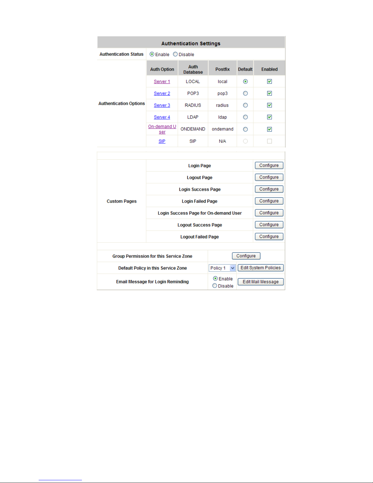
3) Service Zone Setting s – Authentication Settings
Page 44
IAC3000
User Manual
40
¾ Authentication Status: When enabled, users must be authenticated before they get access to the
network within this Service Zone.
¾ Authentication Options: There are total seven types of authentication dat abase (LOCAL, POP3,
RADIUS, LDAP, NTDOMAIN, ONDEMAND, and SIP) that are supported by the entire system. For each
Service Zone, up to six authentication options can be enabled, and one of them can be set as the
default option – so that users do not have to type in the postfix string while entering username during
login.
¾ Custom Pages: Related login and logout pages can be customized by administrators for each service
zone. Please refer to Appendix I. Customizable Pages for more details.
¾ Group Permission for this Service Zone:
For each Service Zone, the administrator can set up multiple groups for that Service Zone. For each
group, an associated policy can be assigned. Therefore, users in the same group follow the same policy
and have the same privileges.
To configure Group permission based on the role of this Service Zone.
Page 45

IAC3000
User Manual
41
Click Configure to have further configuration or view the details.
Click Enabled of the desired Group option(s) to allow the clients of the selected Group(s) to log into this
Service Zone after a successful authentication. Moreover, a pre-defined Policy can be applied to any
Group in this Service Zone.
Click the hyperlink of the respective Group names in the Edit Group Option column to enter the Group
Configuration tab, where zone permission and policy assignment can be further config ured (refer to
Section 4.2.3. Group Configuration).
¾ Default Policy in this Service Zone: For each Service Zone, one policy can be applied to enforce the
access control over the users. Please refer to 4.2.4 Policy Configuration for complete description.
¾ Email Message for Login Reminding: When enabled, the system will automatically send an email to
users if they attempt to send/receive their emails using POP3 email program (for example, Microsoft
Outlook) before they are authenticated. Click Edit Mail Message to edit the message in HTML format:
4) Service Zone Setting s – Wireless Settings
¾ Set SSID: Each service zone can be mapped with its own SSID.
¾ Access Point Security: For each service zone, administrators can set up the wireless security profile,
including Authentication and Encryption.
5) Service Zone Setting s – Managed AP in this Service Zone
Page 46

IAC3000
User Manual
42
All managed APs that belong to this service zone are listed here.
Page 47

IAC3000
User Manual
43
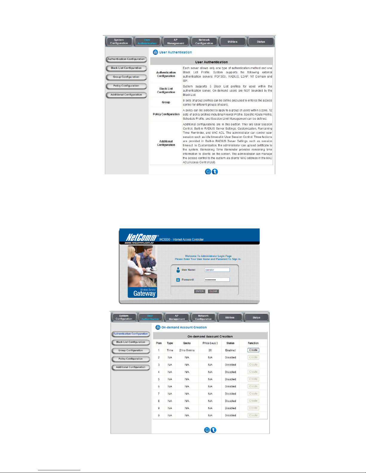
4.2 User Authentication
This section includes the following functions: Authentication Configuration, Black List Configuration, Group
Configuration, Policy Configuration and Additional Configuration.
Page 48

IAC3000
User Manual
44
4.2.1 Authentication Configuration
This section is for administrators to pre-configure authentication servers for the entire system's Service Zones. For
a particular Service Zone, administrators can enable all the authentication servers which will be used and also
specify a default authentication server in the page of Service Zone Settings. Concurrently up to four servers can be
selected and pre-configured here by administrators from the five types of authentication databases (LOCAL,
POP3, RADIUS, LDAP, and NTDOMAIN). In addition, there are two servers (On-demand User and SIP) that are
selected by the system. For the Authentication Settings of each Service Zone, please see 4.1.7 Service Zones.
y Server Name: There are several authentication options supported by IAC3000: Server 1 to Server 4, On-
demand User, and SIP. Click the hyperlink of the respective Server Name to configure the authentication server.
y Auth Method: There are different authentication methods in IAC3000: LOCAL, POP3, RADIUS, LDAP,
NTDOMAIN, ONDEMAND and SIP.
y Postfix: A postfix represents the authentication server in a complete username. For example, user1@local
means that this user (user1) will be authenticated against the LOCAL authentication database.
Note: Concurrently only one server is allowed to be set as LOCAL or NTDOMAIN authentication method.
y Group: An authentication option, su ch as POP3 or NT Domain, can be set as a Group with the same QoS or
Privilege Profile setting.
For more information on Group, please refer to Section 4.2.3. Group Configuration.
Caution: After clicking Apply, there will be a restart message. You m ust click Restart to apply the settings.
Page 49

IAC3000
User Manual
45
y Authentication Server Configuration
IAC3000 provides four authentication servers and one on-demand server that the administrator can apply with
different policy. Click on the server name to set the configuration for that particular server. After completing and
clicking Apply to save the settings, go back to the previous page to select a server to be the default server and
enable or disable any server on the list. Users can log into the default server without the postfix to allow faster
login process.
Server 1~4: There are 5 authentication methods, Local User, POP3, RADIUS, LDAP and NTDomain, to
select from.
Server Name: Set a name for the authentication option by using numbers (0~9), alphabets (a~z or A ~Z),
dash (-), underline (_), space and dot (.) only. The length of this field is up to 40 characters. This name is
used for the administrator to identify the authentication options easily such as HQ-RADIUS.
Postfix: A postfix is used to inform the system which authentication option to be used for authenticating an
account (e.g. bob@MelbourneLdap or tim@SydneyRadius) when multiple options are concurrently in use.
One of authentication option can be assigned as default. For authentication assigned as default, the postfix
can be omitted. For example, if "MelbourneLdap" is the postfix of the default option, Bob can login as "bob"
without having to type in "bob@MelbourneLdap”. Set a postfix that is easy to distinguish (e.g. Local) and
the server numbers (0~9), alphabets (a~z or A~Z), dash (-), underline (_) and dot (.) within a maximum of
40 characters. All other cha racte rs are not allowed.
Caution: The Policy Name cannot contain these words: MAC and IP.
Black List: There are 5 sets of black lists provided by the system. A user accou nt listed in the black list is
not allowed to log into the system, the client's access will be denied. The administrator may select one
black list from the drop-down menu and this black list will be applied to this specific authentication option.
Group: Select one Group from the drop-down list box for this specific authentication option.
Authentication Method: Select Local from the drop-down list box and then click Local User Setting
button to enter the Local User Settings. Then, click the hyperlink of Edit Local User List.
Caution: Enabling two or more servers of the same authentication method is NOT allowed.
Page 50

IAC3000
User Manual
46
4.2.1.1 Local
Choose “Local User” from the Authentication Method field, the button besides the pull-down menu will become
“Local User Setting”.
Click the button of Local User Setting for further configuration.
y Edit Local User List: It let the administrator view / add, and delete local user account. The Upload User
button is for importing a list of user account from a text file. The Download User button is for exporting all
local user accounts into a text file. Clicking on each user account leads to a page for configuring the
individual local account. Local user account can be assigned a policy and applied Local VPN individually.
Check the check box of individual local user account in the Enable Local VPN column to enable individually.
MAC address of a networking device can be bound with a local user as well.
o Edit Local User List: It let the administrator view, add, and delete local user account. The Upload
User button is for importing a list of user account from a text file. The Download User button is for
Page 51

IAC3000
User Manual
47
exporting all local user accounts into a text file. Clicking on each user account leads to a p age for
configuring the individual local account. Local user account can be assigned a policy and applied
Local VPN individually. Check the check box of individual local user account in the Enable Local
VPN column to enable individually. MAC address of a networking device can be bound with a local
user as well.
o Add User: Click this button to enter into the Adding User(s) to the List interface. Fill in the
necessary information such as “Username”, “Password”, “MAC”, and “Remark”. Select a
desired Group to classify local users. Check to enable Local VPN in the Enable Local VPN column.
Click Apply to complete adding the user(s).
Note: Local VPN in IAC3000 is an additional secure login VPN feature for IAC3000 local
users/subscribers. The software design for ‘Local VPN in IAC3000’ is tightly coupled with Active X, which
is supported by Windows-platform Internet Explorer where Active X program is supported.
For more information on Group configuration, please refer to Section 4.2.3. Group Configuration.
o Upload User: Click Upload User to enter the Upload User from File interface. Click the Browse
button to select the text file for uploading user accounts, then click Upload to complete the upload
process.
Page 52

IAC3000
User Manual
48
The uploading file must be a text file and each line should contain the following information in this
specific order: Username, Password, MAC Address, Applied Group, Remark, and Enable
Local VPN. No spaces are allowed between fields and commas. The MAC field can be omitted,
but the trailing comma must be retained. When adding user accounts by uploading a file, the
existing accounts in the embedded database will be remai ned but not replaced by new ones.
o Download User: Use this function to create a .txt file with all built-in user account information and
then save it on disk.
o Search: Enter a keyword of a username to be searched in the text filed and click this button to
perform the search. All usernames matching the keyword will be listed.
Page 53

IAC3000
User Manual
49
o Del All: Click on this button to delete all the users at once and click on Delete to delete the user
individually.
o Edit User: If editing the content of individual user account is needed, click the username of the
desired user account to enter the User Profile Interface for that particular user, and then modify or
add any desired information such as Username, Password, MAC Address (optional), Group
(optional), Enable Local VPN (optional) and Remark (optional). Click Apply to complete the
modification.
y Roaming Out & 802.1X Authentication: When Account Roaming Out is enabled; the link of this function will
be available to define the authorized device with IP address, Subnet Mask, and Secret Key. Please see more
explanation above in the section for Roaming Out and the section for 802.1X Authentication.
Page 54

IAC3000
User Manual
50
Click the hyperlink RADIUS Client List to enter the Radius Client Configuration interface. Choose the
desired type, Disable, Roaming Out or 802.1X, and key in the 802.1X client’s IP address and network
mask and then click Apply to complete the settings.
¾ 802.1X Authentication: When 802.1X Authentication is enabled, the Local authentication
database will be used as a RADIUS database for connection with 802.1x enabled devices such as
APs or switches.
¾ Roaming Out: The system’s local user database can also be an external RADIUS database to
another system. When Account Roaming Out is enabled, local users can login from other domains
with their original local user accounts. The authentication database with their original local user
accounts acts as a RADIUS Server and roaming out local users act as RADIUS clients.
Page 55

IAC3000
User Manual
51
4.2.1.2 POP3
The system supports authentication by an external POP3 authentication server. The system is capable
of supporting two POP3 servers, primary and secondary, for fault tolerance. When POP3
Authentication Database is enabled, at least one external POP3 server must be activated. The Local
VPN function can be enabled for the clients authenticated by POP3 authentication method.
y Name: Set a name for the server using numbers (0~9), alphabets (a~z or A ~Z), dash (-),
underline (_) and dot (.) within a maximum of 40 characters. All other characters are not
allowed.
y Postfix: Set a postfix that is easy to distinguish (e.g. Local) for the server using numbers (0~9),
alphabets (a~z or A~Z), dash (-), underline (_) and dot (.) within a maximum of 40 characters.
All other characters are not allowed.
y Black List: There are five sets of the black lists. Select one of them or choose “None”. For
details, please refer to 4.2.2 Black List Configuration.
y Group: Select one Group from the drop-down list box for this specific authentication option.
y Enable Local VPN: When Local VPN function is enabled for the authentication option, upon
the successful login of a client, a VPN tunnel will be established between a client’s device and
the system. The data passing throu gh the VPN tunnel are encrypted. The system’s Local VPN
supports end-users’ device s under Windows 2000 and Windows XP SP1, SP2.
Note: Local VPN in IAC3000 is an additional secure login VPN feature for IAC3000 local
users/subscribers. The software design for ‘Local VPN in IAC3000’ is tightly coupled with Active X, which
is supported by Windows-platform Internet Explorer where Active X program is supported.
y Authentication Method: Select POP3 from the drop-down list box and then click POP3
Setting button for further configuration.
Page 56

IAC3000
User Manual
52
y Server IP: The IP address of the external POP3 Server.
y Port: The authentication port of the external POP3 Server.
y SSL Setting: The system supports POP3S. Check the check box beside to Enable SSL
Connection to POP3S.
4.2.1.3 RADIUS
The system supports authentication by an external RADIUS authentication server by functioning as a
RADIUS authenticator for the RADIUS server. The system is capable of supporting two RADIUS
servers, primary and secondary, for fault tolerance.
y Name: Set a name for the authentication option by using numbers (0~9), alphabet s (a~z or A ~Z),
dash (-), underline (_) and dot (.) within a maximum of 40 characters. All other characters are not
allowed.
y Postfix: Set a postfix that is easy to distinguish (e.g. Radius) by using numbers (0~9), alphabets
(a~z or A~Z), dash (-), underline (_) and dot (.) within a maximum of 40 characters. All other
characters are not allowed.
A postf ix is used to inform the system which authentication option is used for authenticating an
account (e.g. bob@MelbourneLdap or tim@SydneyRadius) when multiple options are concurrently
in use. One of authentication options can be assigned as default. The postfix can be omitted only
when the default authentication option is used. For example, if "MelbourneLdap" is the postfi x of the
default option, Bob can log in with either "bob" or "bob@MelbourneLdap” as his username.
y Black List: There are five sets of the black lists. A user account listed in the black list is not allowed
to log into the system. Select one black list from the drop-down list box to be applied to this specific
authentication option.
y Group: Select one Group from the drop-down list box for this specific authentication option.
y Enable Local VPN: When Local VPN function is enabled for this authentication option, upon a
Page 57

IAC3000
User Manual
53
successful login of a client, a VPN tunnel will be established between a client’s device and the
system. The data passing through the VPN tunnel are encrypted. The system’s Local VPN supports
client devices under Windows 2000 and Windows XP SP1/SP2.
Note: Local VPN in IAC3000 is an additional secure login VPN feature for IAC3000 local
user/subscribers. The software design for ‘Local VPN in IAC3000’ is tightly coupled with Active X, which
is supported by Windows-platform Internet Explorer where Active X program is supported.
y Authentication Method: Select RADIUS from the drop-down list box and then click Radius Setting
for further configuration as below. Enter the related information for the primary and/or the secondary
RADIUS server (the secondary server is not required). The fields with red asterisk are required. The
settings will take effect immediately after clicking Apply.
802.1X Authentication: The system supports 802.1X . When 802. 1X Authentication is enabled, the
Page 58

IAC3000
User Manual
54
Local Authentication Database will be used as a RADIUS database for connection with 802.1X
enabled devices such as access points or switches.
When the option is enabled, the hyperlink of Radius Client List will appear.
Click the hyperlink of Radius Client List to enter the Radius Client Configuration page. Choose
a desired type from Disable, Roaming Out or 802.1X. Enter the IP Address, Segment (Sub net
Mask), and Secret Key of 802.1X clients. Click Apply to complete the settings.
y Trans Full Name: When Complete option is checked, both the username and postfix will be
transferred to the RADIUS server for authentication. On the other hand, when Only ID option is
checked, only the username will be transferred to the external RADIUS server for authentication.
y NASID: The Network Access Server (NAS) Identifier of the system for the external RADIUS
server.
y Class-Group Mapping: This function is to assign a Group to a RADIUS class attribute sent
from the RADIUS server. Whe n the clients classified by RADIUS class attributes log into the
system via the RADIUS server, ea ch client will be mapped to its assigned Group.
y Server IP: The IP address of the external RADIUS server.
y Authentication Port: Enter the authentication port of the RADIUS server.
y Accounting Port: The accounting port of the external RADIUS server .
y Secret Key: The Secret Key for RADIUS authentication.
y Accounting Service: The system supports RADIUS accounting that can be enabled or disa bled.
y Authentication Protocol: The configuration of the system must match with that of the remote
RADIUS server. PAP (Password Authentication Protocol) transmits passwords in plain text
without encryption. CHAP (Challenge Handshake Authentication Protocol) is a more secure
authentication protocol with hash encryption.
Notice: If the RADIUS Server does not assign idle-timeout value, the IAC3000 will use the local idletimeout.
Page 59

IAC3000
User Manual
55
4.2.1.4 LDAP
The system supports authentication by an external LDAP authentication server. The system is capable
of supporting two LDAP servers, primary and secondary, for fault tolerance.
y Server Name: Set a name for the authentication option by using numbers (0~9), alphabets (a~z or A
~Z), dash (-), underline (_) and dot (.) within a maximum of 40 characters. All other characters are
not allowed.
y Postfix: Set a postfix that is easy to distinguish (e.g. Ldap) by using numbers (0 ~9), alphabets (a~z
or A~Z), dash (-), underline (_) and dot (.) within a maximum of 40 characters. All other characters
are not allowed.
A postf ix is used to inform the system which authentication option is used for authenticating an
account (e.g. bob@MelbourneLdap or tim@SydneyRadius) when multiple options are concurrently
in use. One of authentication options can be assigned as default. The postfix can be omitted only
when the default authentication option is used. For example, if "MelbourneLdap" is the postfi x of the
default option, Bob can log in with either "bob" or "bob@MelbourneLdap” as his username.
y Black List: There are five sets of the black lists. A user account listed in the black list is not allowed
to log into the system. Select one black list from the drop-down list box to be applied to this specific
authentication option.
y Group: Select one Group from the drop-down list box for this specific authentication option.
y Enable Local VPN: When Local VPN function is enabled for this authentication option, upon a
successful login of a client, a VPN tunnel will be established between a client’s device and the
system. The data passing through the VPN tunnel are encrypted. The system’s Local VPN supports
client devices under Windows 2000 and Windows XP SP1/SP2.
Note: Local VPN in IAC3000 is an additional secure login VPN feature for IAC3000 local
users/subscribers. The software design for ‘Local VPN in IAC3000’ is tightly coupled with Active X, which
is supported by Windows-platform Internet Explorer where Active X program is supported.
y Authentication Method: Select LDAP from the drop-down list box and then click LDAP Setting for
further configuration. Enter the related information for the primary and/or the secondary LDAP server
(the secondary server is not required). The fields with red asterisk are required. The settings will
take effect immediately after clicking Apply.
Page 60

IAC3000
User Manual
56
¾ Server IP: The IP address of the external LDAP server.
¾ Port: The authentication port of the external LDAP server.
¾ Base DN: The Distinguished Name for the navigation path of LDAP account.
¾ Account Attribute: The attribute of LDAP accounts.
¾ Attribute-Group Mapping: This function is to assign a Group to a LDAP attribute sent from
the LDAP server. When the clients classified by LDAP attributes log into the system via the
LDAP server, each client will be mapped to its assigned Group. To get and show the attribute
name and value from the configured LDAP server, enter Username and Password and click
Show Attribute. Then, the table of attribute will be displayed. Enter the Attribute Name and
Attribute Value chosen from the attribute table, and select a Group from the drop-down list
box.
Page 61
IAC3000
User Manual
57
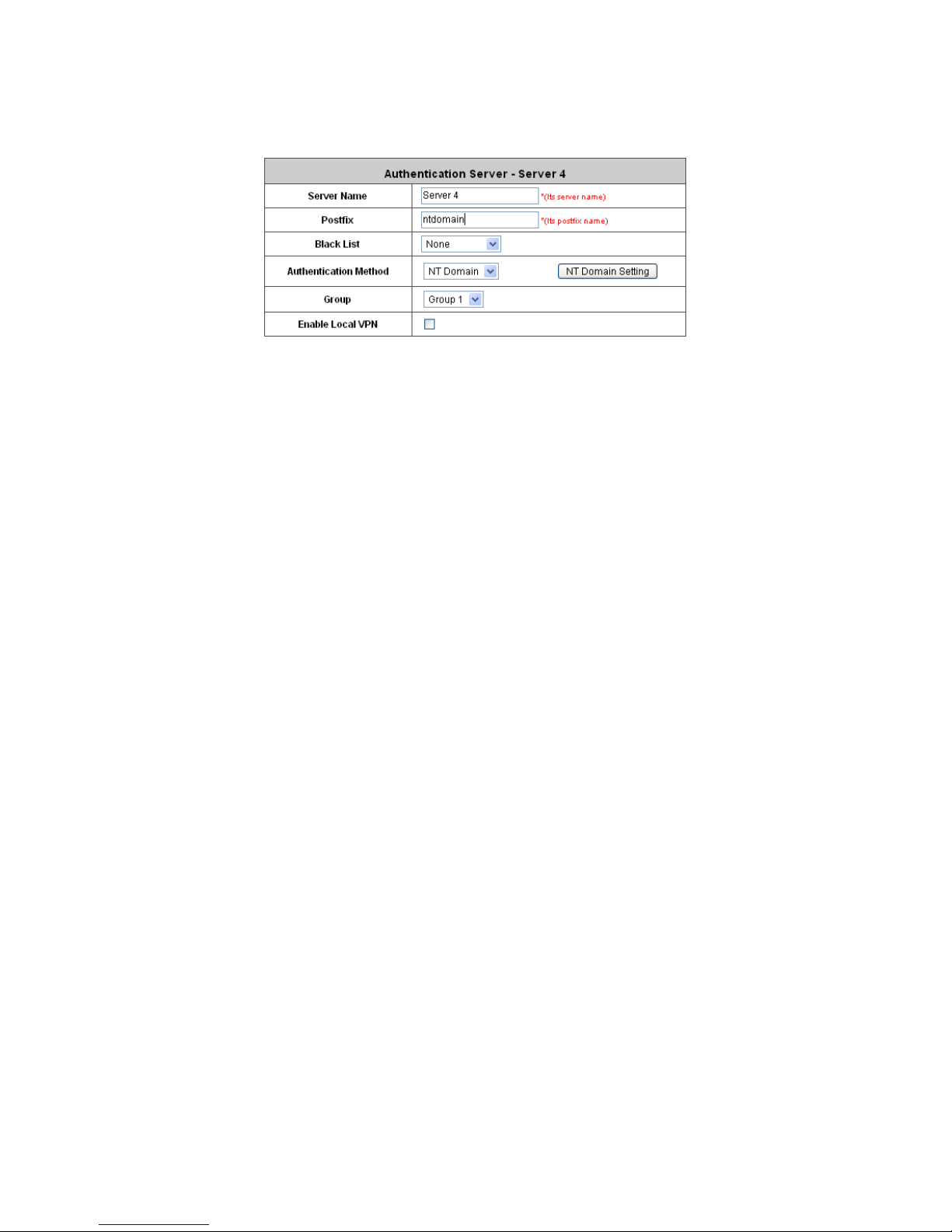
4.2.1.5 NT Domain
The system supports authentication by an external NT Domain auth entication database.
y Server Name: Set a name for the authentication option by using numbers (0~9), alphabets
(a~z or A ~Z), dash (-), underline (_) and dot (.) within a maximum of 40 characters. All other
characters are not allowed.
y Postfix: Set a postfix that is easy to distinguish (e.g. NT-Domain) by using numbers (0~9),
alphabets (a~z or A~Z), dash (-), underline (_) and dot (.) within a maximum of 40 characters.
All other characters are not allowed.
A postf ix is used to inform the system which authentication option is used for authenticating an
account (e.g. bob@MelbourneLdap or tim@SydneyRadius) when multiple options are
concurrently in use. One of authentication options can be assigned as default. The postfix can
be omitted only when the default authentication option is used. For example, if
"MelbourneLdap" is the postfix of the default option, Bob can log in with either "bob" or
"bob@MelbourneLdap” as his username.
y Black List: There are five sets of the black lists. A user account listed in the black list is not
allowed to log into the system. Select one black list from the drop-down list box to be applied to
this specific authentication option.
y Group: Select one Group from the drop-down list box for this specific authentication option.
y Enable Local VPN: When Local VPN function is enabled for this authentication option, upon a
successful login of a client, a VPN tunnel will be established between a client’s device and the
system. The data passing through the VPN tunnel are encrypted. The system’s Local VPN
supports client devices under Windows 2000 and Windows XP SP1/SP2.
Note: Local VPN in IAC3000 is an additional secure login VPN feature for IAC3000 local
users/subscribers. The software design for ‘Local VPN in IAC3000’ is tightly coupled with Active X, which
is supported by Windows-platform Internet Explorer where Active X program is supported.
y Authentication Method: Select NT Domain from the drop-down list box and click NT Domain
Setting to enter the Domain Controller page. The settings will take effect immediately after
clicking Apply.
Page 62

IAC3000
User Manual
58
¾ Server IP: The IP address of the external NT Domain Server.
¾ Transparent Login: This function refers to Windows NT Domain single sign on. When
T ransparent Login is enabled, clients will log in to the system automatically after they have
logged in to the NT domain, which means that clients only need to log in once.
Page 63

IAC3000
User Manual
59
4.2.1.6 ONDEMAND
There are some deployment scenarios (for example, at venues such as coffee shops, hotels, motels,
restaurants, etc.) where retail customers or casual/walk-in visitors want to get wireless Internet access.
To offer the Wi-Fi access (either for commercial use or for free), user accounts should be able to be
created upon request and account tickets/receipts should also be provided. Therefore, On-demand
User is designed as the authentication option for this type of deployment scenarios.
1) General Settings
This is the common setting for the On-demand User authentication option. The generated on-demand
users and all accounts related information such as post fix and unit will be shown in this list.
y Postfix: Postfix is used to inform the system which type of authentication database to be used for
authentication when multiple databases are concurrently in use. Enter the postfix used for ondemand users.
y Monetary Unit: Select the desired monetary unit or specified the unit by users.
y Group Name: Select the desired group for on-demand user.
y WLAN ESSID: The administrator can enter the defined wireless ESSID in this field and it will be
printed on the receipt for on-demand users’ reference when accessing the Internet via wireless
LAN service. The ESSIDs given here should be those of the Service Zones enabled for Ondemand Users.
y Wireless Key: The administrator can enter the defined wireless key such as WEP or WPA in the
field. The Wireless Key will be printed on the receipt for the on-demand users’ reference when
accessing the Internet via wireless LAN service.
y Remaining Volume Sync Internal: While the on-demand user is still logged in, the system will
Page 64

IAC3000
User Manual
60
update the billing notice of the login successful page by the time interval defined here.
y Number of Tickets: Print one or duplicate receipts, when pressing the print button of the ticket
printer which connected to serial port.
2) Ticket Customization
On-demand account ticket can be customized here and previewed on the screen.
Page 65

IAC3000
User Manual
61
y Receipt Header: There are three receipt headers supported by the system. The entered content will
be printed on the receipt. These headers are optional.
y Receipt Footer: The entered content will be printed on the receipt. This footer is optional.
y Background Image: You can choose to customize the ticket by uploading your own background
image for the ticket, or choose the default image or none. Click Browse to select the image file and
then click upload. The background image file size limit is 100 Kbytes. No limit for the dimensions of
the image is set, but a 460x480 image is recommended.
y Preview: Click Preview button, the ticket will be shown including the information of username and
password with the selected background. Print the ticket here.
3) Billing Plans
Administrators can configure several billing plans. Click Edit button to enter the page of Editing Billing
Plan. Click Apply to save the plan that manually set up by the administrators. Go back to the screen of
Billing Plans, click Enable button, and then the plan is activated.
y Plan: The number of the specific plan.
y Type: This is the type of the plan, based on which it defines how the account can be used.
o Time: Total period of time (xx hrs yy mins), during which On-demand users are
allowed to access the network.
Page 66

IAC3000
User Manual
62
o Volume: Tota l traffic volume (xx Mbytes), up to which on-demand users are allowed to
transfer data.
o Cut-off: Specify an absolute clock time of a day (HH: MM; range: 00:00 ~ 23:59) when
the account expires.
y Quota: The limit on how On-demand users are allowed to access the network.
y Price: The unit price of the plan.
y Enable: Click the check box to activate the plan.
y Function: Click the button Edit to add and edit a billing plan.
4) External Payment Gateway
This section is for merchants to set up an external payment gateway to accept paymen ts in order to
provide wireless access service to end customers who wish to pay for the service on-line.
The four options are Authorize.Net, PayPal, Secure Pay and Disable.
Page 67

IAC3000
User Manual
63
Authorize.Net
Before setting up “Authorize.Net”, it is required that the merchant owners have a valid Authorize.Net
account. Please see Appendix A. Accepting Payments via Authorize.Net for more information
about opening an Authoriz e.Net account, relevant maintenance functions, and an example for end
users.
¾ Authorize.Net Payment Page Configuration
Merchant ID: This is the “Login ID” that comes with the Authorize.Net account
Merchant Transaction Key: The merchant transaction key is similar to a password and is used by
Authorize.Net to authenticate transactions.
Payment Gateway URL: This is the default website address to post all transaction data.
Verify SSL Certificate: This is to help protect the system from accessing a website other than
Authorize.Net
MD5 Hash: If transaction responses need to be encrypted by the Payment Gateway, enter and
confirm a MD5 Hash Value and select a reactive mode. The MD5 Hash security feature enables
merchants to verify that the results of a transaction, or transaction response, recei v ed by their server
were actually sent from the Authori ze.Net.
T es t Mode: In this mode, merchants can post test transactions for free to check if the payment
function works properly .
Service Disclaimer Content/ Choose Billing Plan for Authorize.Net Payment Page/Client’s
Purchasing Record
Page 68

IAC3000
User Manual
64
¾ Service Disclaimer Content
View service agreements and fees for the standard payment gateway services here as well as
adding new or editing services disclaimer.
¾ Choose Billing Plan for Authorize.Net Payment Page
These 10 plans are the plans configured in Billing Plans page, and all previously enabled plans can
be further enabled or disabled here, as needed.
¾ Client’s Purchasing Record
Starting Invoice Number: An invoice nu mber may be provided as additional information with a
transaction. The number will be incremented automatically for each following transaction. Click the
“Change the Number” checkbox to change it.
Description (Item Name): This is the item information to describe the product (for example, Internet
Access).
Email Header: Enter the information that should appear in the header of the invoice.
Page 69

IAC3000
User Manual
65
Authorize.Net Payment Page Fields Configuration/ Authorize.Net Payment Page Remark
Content
¾ Authorize.Net Payment Page Fields Configuration
Item: Check the box to show this item on the customer’s payment interface.
Displayed Text: Enter what needs to be shown for this field.
Required: Check the box to indicate this item as a required field.
Credit Card Number: Credit card number of the customer. The Payment Gateway will only accept
card numbers that correspond to the listed card types.
Credit Card Expiration Date: Month and year expiration date of the credit card. This should be
entered in the format of MMYY. For example, an expiration date of July September 2009 should be
entered as 0709.
Card Type: This value indicates the level of match between the Card Code entered on a transaction
and the value that is on file with a customer’s credit card company. A code and narrative description
are provided indicating the results returned by the processor.
Card Code: The three- or four-digit code assigned to a customer’s credit card number (found either
on the front of the card at the end of the credit card number or on the back of the card).
E-mail: An email address may be provided along with the billing information of a transaction. This is
the customer’s email address and should contain an @ symbol.
Customer ID: This is an internal identifier for a customer that may be associated with the billing
Page 70

IAC3000
User Manual
66
information of a transaction. This field may contain any format of information.
First Name: The first name of a customer associated with the billing or shipping address of a
transaction. In the case when John Doe places an order, enter John in the First Name field
indicating this customer’s name.
Last Name: The last name of a customer associated with the billing or shipping address of a
transaction. In the case when John Doe places an order, enter Doe in the Last Name field indicating
this customer’s name.
Company: The name of the company associated with the billing or shipping information entered on
a given transaction.
Address: The address entered either in the billing or shipping information of a given transaction.
City: The city is associated with either the billing address or shipping address of a transaction.
State: A state is associated with both the billing and shipping address of a transaction. This may be
entered as either a two-character abbreviation or the full text name of the state.
Zip: The ZIP code represents the five or nine digit postal code associated with the billing or shipping
address of a transaction. This may be entered as five digits, nine digits, or five di gits and four digits.
Country: The country is associated with both the billing and shipping address of a transaction. This
may be entered as either an abbreviation or full value.
Phone: A phone number is associated with both a billing and shipping address of a transaction.
Phone number information may be entered as all number or it may include parentheses or dashes to
separate the area code and number.
Fax: A fax number may be associated with the billing information of a transaction. This number may
be entered as all number or contain parentheses and dashes to separate the area code and number.
¾ Authorizie.Net Payment Page Remark Content
Enter additional details for the transaction such as Tax, Freight and Duty Amounts, Tax Exempt
status, and a Purchase Order Number, if applicable.
PayPal
Before setting up “PayPal”, it is required that the merchant owners have a valid PayPal “Business
Account”. Please see Appendix B. Accepting Payments via PayPal for more information about
setting up a PayPal Business Account, relevant maintenance functions, and an example for end users.
After opening a PayPal Business Account, the merchant should find the “Identity Token” of this
PayPal account to continue “PayPal Payment Page Configuration”.
Page 71

IAC3000
User Manual
67
¾ PayPal Payment Page Configuration
Business Account: This is the “Login ID” (email address) that is associated with the PayPal Business
Account.
Payment Gateway URL: This is the default website address to post all transaction data.
Identity Token: This is the key used by PayPal to validate all the transactions.
Verify SSL Certificate: This is to help protect the system from accessing a website other than PayPal
Currency: It is the currency to be used for the payment transactions.
Service Disclaimer Content /Choose Billing for Payment Page
¾ Service Disclaimer Content
View service agreements and fees for the standard payment gateway services here as well as
adding new or editing services disclaimer.
¾ Choose Billing Plan for PayPal Payment Page
These 10 plans are the plans configured in Billing Plans page, and all previously enabled plans can
be further enabled or disabled here, as needed.
Page 72

IAC3000
User Manual
68
Enable/Disable: Choose to enable or disable the plan.
Quota: The usage time or condition of each plan.
Price: The price charged for this plan.
Client’s Purchasing Record/ PayPal Payment Page Remark Co ntent
¾ Client’s Purchasing Record
Starting Invoice Number: An invoice nu mber may be provided as additional information with a
transaction. The number will be incremented automatically for each following transaction. Click the
“Change the Number” checkbox to change it.
Description (Item Name): This is the item information to describe the product (for example, Internet
Access).
Title for Message to Seller: Administrators can edit the header “title” of the message note, used in
the PayPal payment page.
¾ PayPal Payment Page Remark Content
The message content will be displayed as a special notice to end customers in the page of “Rat e
Plan”. For example, it can describe the cautions for making a payment via PayPal.
Secure Pay
Before setting up “Secure Pay”, it is required that the merchant owners have a valid Secure Pay
“Business Account”.
Page 73

IAC3000
User Manual
69
¾ Secure Pay Payment Page Configuration
Merchant ID: This is the “Login ID” that is associated with the Secure Pay Business Account.
Merchant Password: This is the Merchant Password that is associated with the Secure Pay Business
Account.
Payment Gateway URL: This is the default website address to post all transaction data.
Verify SSL Certificate: This is to help protect the system from accessing a website other than Secure
Pay
Currency: It is the currency to be used for the payment transactions.
Service Disclaimer Content /Choose Billing for Payment Page
¾ Service Disclaimer Content
View service agreements and fees for the standard payment gateway services here as well as
adding new or editing services disclaimer.
¾ Choose Billing Plan for Secure Pay Payment Page
These 10 plans are the plans configured in Billing Plans page, and all previously enabled plans can
be further enabled or disabled here, as needed.
Enable/Disable: Choose to enable or disable the plan.
Quota: The usage time or condition of each plan.
Price: The price charged for this plan.
Secure Pay Payment Page Remark Content
Page 74

IAC3000
User Manual
70
¾ PayPal Payment Page Remark Content
The message content will be displayed as a special notice to end customers in the page of “Rat e
Plan”. For example, it can describe the cautions for making a payment via Secure Pay.
5) On-demand Account Creation
On-demand accounts are listed and related. When at least one plan is enabled, the administrator can
generate on-demand user accounts here. Click this to enter the On-demand Account Creation screen.
Click on the Create button of the desired plan and an on-demand user account will be created. Click
Print to print a receipt which will contain the on-demand user’s information, including the username
and password.
Note: If no Billing plan is enabled, accounts cannot be created by clicking Create button. Please goes back to
Billing Plans to active at least one Billing plan by clicking Edit button and Apply the setting to activate the plan.
The printer used by Print is a pre-configured printer connected to the administrator’s computer.
y Plan: The number of a specific plan.
y Type: Show one type of the plan in Time, Volume or Cut-off.
y Quota: The Time Volume is how long the on-demand user is allowed to access the Internet.
y Price: The unit price of each plan.
Page 75

IAC3000
User Manual
71
y Status: Show the status in enabled or disabled.
y Function: Press Create button for the desired plan. You can add an operator’s remark and press
the Create button again. An On-demand user account will be created, and then click Printout to
print a receipt which will contain this on-demand user’s information.
Page 76

IAC3000
User Manual
72
6) On-demand Account List
All created On-demand accounts are listed and related information on is also provided.
y Search: Enter a keyword of a username to be searched in the text filed and click this button to
perform the search. All usernames matching the keyword will be listed.
y Username: The login name of the user.
y Password: The login password of the user.
y Remaining Quota: The remaining time or volume that the user can continue to use to access the
network.
y Status: The status of the account.
¾ Normal: the account is not currently in use and also does not exceed the quota limit.
¾ Online: the account is currently in use.
¾ Expired: the account is not valid any more, even there is remaining quota to be used.
¾ Out of Quota: the account has exceeded the quota limit
¾ Redeemed: the account has been applied for account renewal.
y Remark: The remark added by the operator at the time of ticket creation.
y Delete All: This will delete all the users at once.
y Delete: This will delete the users individually.
Page 77

IAC3000
User Manual
73
4.2.1.7 SIP
The system provides SIP proxy for SIP clients (devices or soft clients) pass through NAT. After enable
SIP proxy server , all SIP traffic can pass through NA T with a selective but fixed WAN interface.
Administrator will be able to add up to four trusted SIP Registrars. A group can be chosen to govern
SIP traffic.
y SIP: SIP authentication supports 4 Trusted SIP Registrar.
y IP Address: The IP address of the Trusted SIP Registrar.
y Remark: The administrator can enter extra information in this field for remark.
y Group: A Group option can be applied to the clients who login with SIP Authentication. Be noted
that the specific route of the applied Policy for the selected Group cannot conflict with the
assigned WAN interface for SIP authentication.
Page 78

IAC3000
User Manual
74
4.2.2 Black List Configuration
The administrator can add, delete, or edit the black list for user access control. Each black list can include u p to 40
users. Users’ accounts that appear in the black list will be denied of network access. The administrator can use the
pull-down menu to select the desired black list.
y Select Black List: There are 5 lists to select from for the desired black list.
y Name: Set the black list name and it will show on the drop down box above.
y Add User to List: Click the hyperlink to add users to the selected black list.
After entering the usernames in the “Username” blanks and the related information in the “Remark” blank
(not required), click Apply to add the users.
Page 79

IAC3000
User Manual
75
If removing a user from the black list is desired, select the user’s “Delete” check box and then click the Delete
button to remove that user from the black list.
Page 80

IAC3000
User’s Manual
76
4.2.3 Group Configuration
There are 8 groups to choose from. Local users can be classified by applying Group optio ns. A Group whi c h is
allowed to access a Service Zone can be applied with a Policy within this zone. The same Group within different
Service Zones can be applied with different Policies as well as different Authentication Options.
y Group Configuration – Group 1
¾ QoS Profile: Set parameters for traffic classification.
o Traffic Class: A Traffic Class can be chosen for a Group of users. There are four traffic classes:
Page 81

IAC3000
User’s Manual
77
Voice, Video, Best-Effort and Background. Voice and Video traffic will be placed in the high priority
queue. When Best-Effort or Background is selected, more band width management options such as
Downlink and Uplink Bandwidth will appear.
o Group Total Downlink: Defines the maximum bandwidth allowed to be shared by clients within this
Group.
o Individual Maximum Downlink: Defines the maximum downlink bandwidth allowed for an individual
client belonging to this Group. The Individual Maximum Downlink cannot exceed the value of Group
Total Downlink.
o Individual Request Downlink: Defines the guaranteed minimum downlink bandwidth allowed for an
individual client belonging to this Group. The Individual Request Downlink cannot exceed the v alue
of Group Total Downlink and Individual Maximum Downlink.
o Group Total Uplink: Defines the maximum uplin k bandwidth allowed to be shared by clients within
this Group.
o Individual Maximum Uplink: Defines the maximum uplink bandwidth allowed for an individual client
belonging to this Group. The Individual Maximum Uplink cannot exceed the value of Group Total
Uplink.
o Individual Request Uplink: Defines the guaranteed minimum bandwidth allowed for an individual
client belonging to this Group. The Individual Request Uplink cannot exceed the value of Grou p Total
Uplink and Individual Maximum Uplink.
¾ Privilege Profile:
o Change Password Privilege: When Change Password Privilege is enabled, the authenticated local
users within this Group are allowed to change their password via the Login Success Page.
Page 82

IAC3000
User’s Manual
78
y Zone Permission Configuration & Policy Assignment – Grou p X
A Group can be assigned to one Service Zone or multiple Service Zones. Moreover, a Group can be applied
with different Policies within different Service Zo nes. Remote VPN is considered as a zone, where clients log
into the system via remote VPN.
¾ Name: The name of Service Zones and Remote VPN.
¾ Enabled: Select Enabled to allow clients of this Group to log into the selected Service Zones. For
example, the above figure shows that users in Group 1 can access network services via every Service
Zone as well as Remote VPN under constraints of Policy 1.
¾ Policy: Select a Policy that the Group will be applied with when accessing respective Service Zones.
¾ Edit Group Permission: The relation between Group and Service Zone is many to many; every Group
can access network services via more than one Service Zone, and meanwhile, each Service Zone can
serve more than one Group.
Click the hyperlink in the Edit Group Permission column to enter the Group Configuration interface, which
is based on the role of Service Zone, to configure the relation between Group and Zone.
Page 83

IAC3000
User’s Manual
79
o Group Option: The name of Group options available for selection.
o Enabled: Select Enabled to allow clients of the enabled Groups to log in to this Service Zone under
constraints of the selected Policies.
Check Enabled of the respected Group to assign it/them to the Service Zone listed. For example, the
above figure shows, clients in Group 1~8 can access Default Service Zone, where they are governed
by Policy 1~8 respectively.
o Policy: Select a Policy that the Group will be applied with when accessing this Service Zone.
o Edit Group Option: Click the hyperlink in the Edit Group Option column to enter Zone Permission
Configuration & Policy Assignment interface, which is based o n the role of Group, to configure the
relation between Group and Zone.
Page 84

IAC3000
User’s Manual
80
4.2.4 Policy Configuration
IAC3000 supports multiple Policies, including one Global Policy and 12 individual Policy. Each Policy consists of
access control profiles that can be configured respectively and applied to a certain Group of users. Global Policy
is the system’s universal policy and applied to all clients, while other individual Policy ca n be selected and defined
to be applied to any Service Zone.
The clients belonging to a Service Zone will be bound by an applied Policy. In addition, a Policy can be applied at a
Group basis; a Group of users can be bound by a Policy. The same Group can be applied with different Policies
within different Service Zones.
When the type of authentication database is RADIUS, the Class-Group Mapping function will be available to allow
the administrator to assign a Group for a RADIUS class attribute; therefore, a Policy applied to this Group will be
mapped to a user Group of a RADIUS class attribute. When the type of authentication database is LDAP, the
Attribute-Group Mapping function will be available to allow administrator to assign a Group for LDAP Attribute;
therefore, a Policy applied to this Group will be mapped to a user Group of a LDAP attribute. When the type of
database is SIP, the Group selection function will be available to allow administrator to assign a Group option for all
SIP clients.
4.2.4.1 Global Policy
Global is the system’s universal policy including Firewall Rules, Specific Routes Profile and Maximum
Concurrent Session which will be applied to all users unless the user has been regulated and applied to another
policy.
y Select Policy: Select Global to set the Firewall Profile, Specific Route Profile and Privilege Profile.
y Firewall Profile: Global policy and each policy have a firewall service list and a set of firewall profile which is
composed of firewall rules.
y Specific Route Profile: The default gateway of WAN1, WAN2, or a desired IP address can be defined in a
policy. When Specific Default Route is enabled, all clients applied this policy will access the Internet through
this default gateway.
y Maximum Concurrent Sessions: Set the maximum concurrent sessions for each client.
Page 85

IAC3000
User’s Manual
81
¾ Firewall Profile: Click Setting for Firewall Profile. The Firewall Configuration will appear. Click
Predefined and Custom Service Protocols to edit the protocol list. Click Firewall Rules to edit the rules.
o Predefined and Custom Service Protocols: There are predefined service protocols available for
firewall rules editing. The administrator is able to add new custom service protocols by clicking Add,
and delete the added protocols with Select All and Delete operations.
This link leads to a Service Protocols List where the administrator can defined a list of service by
protocols (TCP/UDP/ICMP/IP).
o Firewall Rules: Click the number of Filter Rule No. to edit individual rules and click Apply to save the
settings. The rule status will show on the list. Check “Active” box and click Apply to enable that rule.
This link leads to the Firewall Rules page. Rule No.1 has the highest priority; Rule No.2 has the second
priority and so on. Each firewall rule is defined by Source, Destination and Pass/Block action.
Optionally, a Firewall Rule Schedule can be set to specify when the firewall rule is enforced. It can be
set to Always, Recurring or One Time.
Selecting the Filter Rule Number 1 as an example:
Page 86

IAC3000
User’s Manual
82
o Rule Number: This is the rule selected “1”. Rule No. 1 has the highest priority; rule No. 2 has the
second priority, and so on.
o Rule Name: The rule name can be changed here.
o Source/Destination – Interface/Zone: There are choices of ALL, WAN1, WAN2, Default, and
the named Service Zones to be applied for the traffic interface.
o Source/Destination – IP Address/Domain Name: Enter the source and destination IP
addresses. Domain Host filtering is supported but Domain name filtering is not.
o Source/Destination – Subnet Mask: Select the source and destination subnet masks.
o Source- MAC Address: The MAC Address of the source IP address. This is for specific MAC
address filter.
o Source/Destination – IPSec Encrypted: Check the box for only filtering on the encrypted traffic.
o Service Protocol: There are defined protocols in the service protocols list to be selected.
o Schedule: When schedule is selected, clients assigned with this policy are applied the firewall
rule only within the time checked. There are three options, Always, Recurring and One Time.
Recurring is set with the hours within a week.
o Action for Matched Packets: There are two options, Block and Pass. Block is to prevent
packets from passing and Pass is to permit packets passing.
¾ Specific Route Profile: Click the button of Setting for Specific Route Profile, the Specific Route Profile
list will appear.
o
Route No.: The number of route.
o
IP Address (Destination): The destination IP address of the host or the network.
o
Subnet Netmask: Select a destination subnet netmask of the host or the network.
o
IP Address (Gateway): The IP address of the next router to the destination.
Page 87

IAC3000
User’s Manual
83
¾ Maximum Concurrent Session for User: Include Maximum Concurrent Session for User, from 10 to
Unlimited. The concurrent sessions for each user, it can be restricted by administrator.
Note: For more information, please refer to Appendix E. Session Limit and Session Log.
4.2.4.2 Policy 1~12
Polices can be defined in the Policy tab. The administrator can select one of the defined policies to apply it to the
specific authentication option. All clients belong to this authentication option will be bound by this policy. A policy
could be applied at zone level, at group level or at user level. User level policy overrides group level policy. Group
level policy overrides zone level policy. Zone level policy overrides the global policy.
When the type of authentication database is “Local”, a policy is applied at per user basis. When the type of
database is NTDOMAIN or ONDEMAND, a policy is applied to the whole user database. When type of database is
RADIUS, a policy is mapped to a user group of a RADIUS class. The Class-Policy Mappin g functio n will be
available to let the administrator assign a policy for a RADIUS Class attribute. When the type of database is LDAP,
a policy is applied to user group defined an attribute-value pair. The Attribute-Policy Mapping function will be
available to let administrator assign a policy for a LDAP Attribute. When the type of database is SIP, the Policy
selection function will be available to let the administrator assign a policy for all SIP users.
y Select Policy: Select a Policy for further configuration. Below depicts an example of selecting Po licy 1.
y Firewall Profile: Each Policy has a firewall service list and a set of firewall profile consisting of firewall rules.
y Select Policy: Select Policy1~Policy12 to set the Firewall Profile, Specific Route Profile, Schedule Profile
and Maximum Concurrent Session.
y Firewall Profile: Each Policy has a firewall service list and a set of firewall profile consisting of firewall rules.
y Specific Route Profile: The default gateway of WAN1, WAN2, or a desired IP address can be defined in a
policy. When Specific Default Route is enabled, all clients applied this policy will access the Internet through
this default gateway.
y Schedule Profile: The Schedule table in a 7X24 format is used to control the clients’ login time. When
Schedule is enabled, clients applied policies are only allowed to login the system at the time which i s ch ecked
in the applied policy.
y Maximum Concurrent Sessions: Set the maximum concurrent sessions for each client.
Page 88

IAC3000
User’s Manual
84
¾ Firewall Profile: Click Setting for Firewall Profile. The Firewall Configuration will appear. Click
Predefined and Custom Service Protocols to edit the protocol list. Click Firewall Rules to edit the rules.
o Predefined and Custom Service Protocols: This link leads to a Service Protocols List where the
administrator can defined a list of service by protocols (TCP/UDP/ICMP/IP). There are predefined
service protocols available for firewall rules editing. The administrator is able to add new customized
service protocols by clicking Add, and delete the added protocols by clicking Delete.
o Firewall Rules: Click on the hyperlink in the No. column to edit individual rules and then click Apply to
save the settings. The rule status will show on the list. Check the Active check box and click Apply to
enable that rule. This link leads to the Firewall Rules page. Rule No.1 has the highest priority; Rule
No.2 has the second priority and so on. Each firewall rule is define d by Source, Destination and
Pass/Block action. Optionally, a Firewall Rule Schedule can be set to specify when the firewall rule is
enforced. It can be set to Always, Recurring or One Time.
Below depicts an example of selecting Filter Rule Number 1:
Page 89

IAC3000
User’s Manual
85
o Rule Item: This rule number of the selected rule. Rule No. 1 has the highest priority; Rule No. 2
has the second priority, and so on.
o Rule Name: The rule name can be changed here.
o Source / Destination – Interface/Zone: There are choices of ALL, WAN1, WAN2, Default and the
Service Zones to be applied to the traffic interface.
o Source / Destination – IP Address/Domain Name: Enter the source and destination IP
addresses.
o Source / Destination – Subnet Mask: Enter the source and destination subnet masks.
o Source / MAC Address: The MAC Address of the source IP address. This is for specific MAC
address filter.
o Source / Destination – IPSec Traffic: Check the box to filter the encrypted traffic only.
o Service Protocol: Select a defined protocol from the drop-down list box.
o Schedule: Defines the time when this firewall rule will be activated. When a schedule is selected,
the clients assigned to this Policy are applied with the firewall rule only within the time selected.
There are three options, Always, Recurring and One Time.
o Action for Matched Packets: There are two options, Block and Pass. Block is to prevent packets
from passing, while Pass is to permit packets passing.
¾ Specific Route Profile: The default gateway of WAN1, WAN2, or a desired IP address can be defined in a
Policy. When Specific Default Route is enabled, all clients applied with this Policy will access the Internet
through this default gateway.
Click Setting of Specific Route Profile to enter the Specific Route page for further configuration.
Page 90

IAC3000
User’s Manual
86
o Enable: Check Enable box to activate this function or uncheck to inactivate it.
o Destination / IP Address: The destination network address or IP address of the destination host.
Please note that, if applicable, the system will calculate and display the appropriate value based on the
combination of Network/IP Address and Subnet Mask that are just entered and applied.
o Destination / Subnet Netmask: The subnet mask of the destination network. Select
255.255.255.255(/32) if the destination is a single host.
o Gateway / IP Address: The IP address of the gateway or next router to the destination.
¾ Schedule Profile: Click Setting of Schedule Profile to enter the configuration page. Select Enable to show
the Permitted Login Hours list. This function is used to limit the time when clients can log in. Check the
desired time slots and click Apply to save the settings. These settings will become effective immediately
after clicking Apply.
¾ Maximum Concurrent Session for User: Include Maximum Concurrent Session for User, from 10 to
Unlimited. The concurrent sessions for each user, it can be restricted by administrator.
Note: For more information, please refer to Appendix E. Session Limit and Session Log.
Page 91

IAC3000
User’s Manual
87
4.2.5 Additional Configuration
y User Control: Functions under this section apply to all general users.
Idle Timer: If a user has idled with no network activities, the system will automatically kick out the user. The
logout timer can be set between 1~1440 minutes, and the default logout time is 10 minutes.
Multiple Login: When enabled, a user can log in from different computers with the same account. (This
function doesn’t support On-demand users and RADIUS authentication.)
y Roaming Out Timer:
Session Timeout: The time that the user can access the network while roaming. When the time is up, the user
will be kicked out automatically.
Idle Timeout: If a user has idled with no network activities, the system will automatically kick out the user.
Interim Update: The system will update the users’ current status and usage according to this time period.
y Upload File
SSL Certificate
A dat a record used for authenticating network entities such as a server or a client. A certificate contains X.509
information pieces about its owner (called the subject) and the signing Certificate Authority (called the issuer),
plus the owner's public key and the signature made by the CA. Network entities verify these signatures using
CA certificates. You can apply for a SSL certificate at CAs such as VeriSign.
If you already have an SSL Certificate, please Click Browse to select the file and upload it. Click Apply to
complete the upload process.
Page 92

IAC3000
User’s Manual
88
Without a valid certificate, users may encounter the following problem in IE7 when they try to open the
login page.
Click “Continue to this website” to access the user login page.
T o Use Default Certificate: Click Use Default Certificate to use the default certificate and key. Click restart to
validate the changes.
y Credit Reminder: The administrator can enable this function to remind the on-demand users before their credit
run out. There are two kinds of reminder, Volume and Time. The default reminding trigger level for Volume is
1Mbyte and the level for Time is 5 minutes.
Page 93

IAC3000
User’s Manual
89
y Enhance User Authentication: With this function, only the users with their MAC addresses in this list can log
into IAC3000. There are 40 users maximum allowed in this MAC address list. User authentication is still
required for these users. Please enter the Permit MAC Address List to fill in these MAC addresses, select
Enable, and then click Apply.
Caution: The format of the MAC address is: xx:xx:xx:xx:xx:xx or xx-xx-xx-xx-xx-xx.
Page 94

IAC3000
User’s Manual
90
4.3 AP Management
IAC3000 supports to manage up to 12 NP725 access points (AP), and they can be configured in this section. This
section includes the following functions: AP List, AP Discovery, Manual Configuration, Template Settings,
Firmware Management, AP Upgrade and WSD Management.
Page 95

IAC3000
User’s Manual
91
4.3.1 AP List
All of the APs under the management of IAC3000 will be shown in the list. The AP can be edited by clicking the
hyperlink of AP Name and the AP status can be got by clicking the h yperlink of Status.
After adding an AP:
Check any AP and click the button below to Reboot, Enable, Disable, Delete, Apply Template and Apply
Service Zone to the checked AP.
y AP Name
The AP name will be shown as hyperlink. Click the hyperlink of each managed AP can have for configurations
about the specific AP. Click the hyperlink of the AP Name to have more configurations. There are four kinds of
settings available: General, LAN, Wireless LAN and Access Control. Click the hyperlink of each individual
setting to have further configurations.
y Service Zone
After the AP is added into AP List, the managed AP can be assigned to one or multiple service zone.
y Status:
Each AP’ s status will be shown in this column. Click the hyperlink of the shown status of each managed AP to
see detailed status information about the specific AP, such as System Status, Service Zone Status, Wireless
Status, Access Control Status and Associated Client Status. The status includes:
(1) Online: The hyperlink of Online (Enabled)
indicates that the AP is currently online and in service; Online
(Disabled) indicates that the AP is currently online but not ready in service.
(2) Offline: The AP is currently offline; for example: it is displayed as Offline
when the power of the AP is off
or the network connection between the AP and the system is down.
(3) Configuring: It is displayed as Configuring
when the newly discovered AP is being added to the list (and
being configured) or new setting is being applied to the AP.
(4) Upgrading: The AP is undergoing firmware upgra de.
(5) Lost/Unknown: After the system’s rebooting and before it tries to probe the AP and determine the exact
status, the status will be displayed as Lost
or Unknown temporarily.
Check any AP and then click the button below to Reboot, Enable, Disable and Delete the checked AP if desired.
Page 96

IAC3000
User’s Manual
92
Click Apply Template to select one template to apply to the AP.
Click Apply Service Zone to setup one Service Zone to the AP.
Page 97

IAC3000
User’s Manual
93
y AP Name
Click AP Name and enter the interface about related settings. There are four kinds of settings, General
Settings, LAN Interface Setting, Wireless Interface Setting and Access Control Setting. Click the
hyperlink to go on the configuration.
¾ General Setting: Click Setting to enter the General Setting interface. Firmware information can be
observed here.
Page 98

IAC3000
User’s Manual
94
¾ LAN Setting: Click LAN to enter the LAN Setting interface. Input the data of LAN including IP address,
Subnet Mask and Default Gateway of AP.
¾ Wireless LAN: Click Wireless LAN to enter the Wireless interface. The data of Properties and Security
need to be filled.
Properties
y SSID Broadcast: Select this option to enable the SSID to broadcast in the network. When configuring
the network, it’s suggested to enable this function but also make sure to disable it when finished. With
this enabled, someone could easily obtain the SSID information with the site survey software and get
unauthorized access to an individual’s network. With this disabled to increase network security and
prevent the SSID from being seen on networked.
y Channel: Select the appropriate channel from the list to correspond with the network settings
y Wireless b/g Mode: There are 3 modes to select from, 802.11b (2.4G, 1~11Mbps), 802.11g (2.4G,
54Mbps) and 802.11b+802.11g (b and g).
Page 99

IAC3000
User’s Manual
95
y Data Rate: The default is Auto. Available range is from 1 to 54Mbps. The rate of data transmission
should be set depending on the speed of the wireless network. Sele ct from a range of transmission
speed is desired or keep the default setting, Auto, to make the Access Point automatically use the
fastest rate possible.
y Fragment Length: Breaking a packet into smaller units when transmitting over a network medium that
cannot support the original size of the packet.
y RTS Threshold: Enter the desired RTS Threshold value, the range is from 0 to 2347, and the default is
2347.
y Beacon Interval (ms): Enter a value between 20 and 1000 msec. The default value is 100
milliseconds. The entered time means how often the beacon signal transmits between the access point
and the wireless network.
y Preamble: Select from either Short Preamble or Long Preamble; the short preamble provides 56 bits
Synchronization field to improve WLAN transmission efficiency.
y Transmit Power: Choose the suitable value from the drop-down box.
y Wireless QoS WMM: Enable or disable QoS and WMM. WMM maintains the priority of audio, video
and voice applications in a Wi-Fi network.
y Wireless Client Isolation: Enable or disable Client Isolation. Client Isolation prevents wirele ss
client to wireless client traffic.
y IAPP: Inter Access-Point Protocol is designed for the enforcement of unique association throughout a
ESS (Extended Service Set) and for secure exchange of station’s security context between current
access point (AP) and new AP during handoff period.
¾ Access Control: In this function, when the status is “Allowed”, only these clients whose MAC addresses
are listed in this list can be allowed to connect to the AP; on the other hand, when the status is “Denied”,
the clients whose MAC addresses are listed in the list will be denied to connect to the AP. When
“Disabled” is selected, all clients can connect to the AP. The default is Disabled.
o User Limit: Limit the number of users connected to that AP.
Page 100

IAC3000
User’s Manual
96
4.3.2 AP Discovery
Use this function to detect and manage all of the APs in the network segments. Note that IAC3000 can only
manage APs that are conn ected to its LAN ports. Therefore, the AP discovery function is for adding locally
connected APs to its management list. The administrator must know the local IP addresses of the APs he/she
wishes to discover.
y To discover AP manually, please fill in the required data.
¾ AP Type: Choose the type of AP you wish to discover.
¾ Interface: Set to default.
¾ Admin Settings Used to Discover: Choose from Factory Default or Manual.
¾ IP Addresses of APs after Discovery: Start assigning from this IP address to discovered APs.
Then click the Scan Now button and the APs match the given settings will show in the list below. If one of the
IP addresses intended is used, a warning message will sho w up. In this ca se, please change the IP range and
then click Scan Now again. Input the desired name and password for the AP. Select one template check it and
then click Add to add it under the managed list. (About the template, please see 4.3.4 Template Settings).
When the matched AP is discovered, it will show up in the list below and be given a new IP address set here
(ex: 192.168.25.1). Check the Add box to add the AP and it will be listed to the AP list. When an AP is added,
its MAC address will be automatically recorded into MAC Privilege List (please see 4.4.2 Privilege List) so its
management page can be accessed.
Click Configuring to go on the related configuration. For the details, please refer to 4.3.1 AP List.
y Background AP Discovery: Click Configure to enter Background AP Discovery interface to go on related
 Loading...