

Page 1
TELSTRA ULTIMATE GATEWAY
DC-HSPA+ 42Mbps Wi-Fi Router
3G42WT
USER GUIDE
Page 2

2
NetComm 3G42WT – DC-HSPA+ 42Mbps Wi-Fi Router
YML42T
www.netcomm.com.au
DOCUMENT VERSION
DATE
1.0 - Initial document release
01/09/2011
1.1 - New UM style applied
20/09/2011
Copyright
Copyright©2011 NetComm Limited. All rights reserved.
The information contained herein is proprietary to NetComm Limited. No part of this document may be translated, transcribed,
reproduced, in any form, or by any means without prior written consent of NetComm Limited.
Please note: This document is subject to change without notice.
Save Our Environment
When this equipment has reached the end of its useful life, it must be taken to a recycling centre and processed separately from
domestic waste.
The cardboard box, the plastic contained in the packaging, and the parts that make up this device can be recycled in accordance
with regionally established regulations. Never dispose of this electronic equipment along with your household waste. You may be
subject to penalties or sanctions under the law. Instead, ask for disposal instructions from your municipal government.
Please be responsible and protect our environment.
This manual covers the following products:
NetComm 3G42WT
Page 3

www.netcomm.com.au
3
TELSTRA ULTIMATE GATEWAY – 3G42WT – DC-HSPA+ 42Mbps Wi-Fi Router
NetComm 3G42WT – DC-HSPA+ 42Mbps Wi-Fi Router
YML42T
Table of Contents
Overview ........................................................................................................................................................................................ 4
Introduction ................................................................................................................................................................................................... 4
Target Users .................................................................................................................................................................................................. 4
Prerequisites.................................................................................................................................................................................................. 4
Notation ........................................................................................................................................................................................................ 4
Product Introduction ..................................................................................................................................................................... 5
Product Overview .......................................................................................................................................................................................... 5
Package Contents ......................................................................................................................................................................................... 5
Product Features ........................................................................................................................................................................................... 5
Physical Dimensions and Indicators ............................................................................................................................................ 6
LED Indicators ............................................................................................................................................................................................... 6
Physical Dimensions ...................................................................................................................................................................................... 7
3G42WT Default Settings ............................................................................................................................................................................... 7
Integrated Interfaces ..................................................................................................................................................................... 8
Safety and Product Care ............................................................................................................................................................... 9
Transport and Handling ................................................................................................................................................................. 9
Installation and Configuration of the 3G42WT ........................................................................................................................... 10
Placement of your 3G42WT ......................................................................................................................................................................... 10
Hardware installation.................................................................................................................................................................................... 11
Connecting via a cable ................................................................................................................................................................................. 11
Connecting wirelessly .................................................................................................................................................................................. 11
Quick Setup ................................................................................................................................................................................................ 12
Web User Interface ...................................................................................................................................................................................... 12
Basic ........................................................................................................................................................................................................... 13
Next G Settings ........................................................................................................................................................................................... 14
Wireless ...................................................................................................................................................................................................... 17
Management ............................................................................................................................................................................................... 22
Advanced Settings....................................................................................................................................................................................... 26
Status ......................................................................................................................................................................................................... 35
Troubleshooting ........................................................................................................................................................................... 40
Appendix A: Print Server ............................................................................................................................................................. 41
For Windows Vista/7 .................................................................................................................................................................................... 41
For MAC OSX .............................................................................................................................................................................................. 43
Appendix B: USB Storage ........................................................................................................................................................... 45
For Windows Vista/7 .................................................................................................................................................................................... 45
For MAC OSX .............................................................................................................................................................................................. 45
Legal & Regulatory Information................................................................................................................................................... 46
Contact......................................................................................................................................................................................... 48
Page 4

4
NetComm 3G42WT – DC-HSPA+ 42Mbps Wi-Fi Router
YML42T
www.netcomm.com.au
Overview
Introduction
This manual provides information related to the installation, operation, and utilisation of the 3G42WT.
Target Users
The individual reading this manual is presumed to have a basic understanding of telecommunications terminology and concepts.
Prerequisites
Before continuing with the installation of your 3G42WT, please confirm that you comply with the minimum system requirements
below.
An activated 3G SIM
Computer with Windows, Macintosh, or Linux-based operating systems with a working Ethernet adapter with TCP/IP
Protocol installed.
A Web Browser such as Internet Explorer, Netscape Navigator, Mozilla Firefox, Opera, Safari etc.
Wireless Computer System Requirements:
o
Computer with a working 802.11b, 802.11g or 802.11n wireless adapter.
Notation
The following symbols are utilised in this user manual:
-
The following note requires attention
-
The following note provides a warning
-
The following note provides relevant information
Page 5

www.netcomm.com.au
5
TELSTRA ULTIMATE GATEWAY – 3G42WT – DC-HSPA+ 42Mbps Wi-Fi Router
NetComm 3G42WT – DC-HSPA+ 42Mbps Wi-Fi Router
YML42T
Product Introduction
Product Overview
Combines DC-HSPA+, Wireless 11n 300Mbps, 4 Ethernet ports
Worldwide coverage through Quad-band HSUPA/HSDPA/UMTS (850 / 900 / 1900 / 2100 Mhz), quad-band
EDGE/GSM (850 / 900 / 1800 / 1900Mhz)
Integrated 802.11n AP (backward compatible with 802.11b/g)
UPnP
WEP/WPA/WPA2 and 802.1x
MAC address and IP filtering
Static route functions
DNS Proxy
NAT/PAT
Embedded Sierra Wireless MC8801 multimode HSUPA/HSDPA/UMTS/EDGE/GPRS/GSM module
CLI command interface
1. Speeds are dependent on network coverage. See your 3G provider coverage maps for more details. The total number of Wi-Fi users can also affect data speeds.
Maximum wireless signal rate and coverage values are derived from IEEE Standard 802.11g and 802.11n specifications. Actual wireless speed and coverage are
dependent on network and environmental conditions included but not limited to volume of network traffic, building materials and construction/layout.
2 x USB ports (for Print server functionality or accessing USB Storage)
Package Contents
The 3G42WT package consists of:
3G42WT - Telstra Ultimate Gateway Router
Printed Quick Start Guide
USB Key (Setup Wizard Configuration Software)
Ethernet Cable
Wireless Security Card
Power Supply
If any of these items are missing or damaged, please contact NetComm Support immediately by visiting the NetComm Support
website at:
http://www.netcomm.com.au/contact-us/technical-support
Product Features
Designed to keep up with the world’s fastest networks, this DC-HSPA+ device is capable of downlink speeds of up to 42Mbps.
With wireless N, this device also provides multiple wireless devices with local wireless speeds of up to 300Mbps. Its stylish vertical
design incorporates a unique cable management design hiding up to 5 cables.
Page 6
6
NetComm 3G42WT – DC-HSPA+ 42Mbps Wi-Fi Router
YML42T
www.netcomm.com.au
INDICATOR
Off
Router powered off or on other signal strength
Off
Router powered off or on other signal strength
Off
Router powered off or on other signal strength
Off
No connection available or Next G service in use
On
Connection established with 2G network
Off
No connection available or 2G service in use
On
Connection established with Next G network
Blinking
Connecting with Next G network
supplied to an Ethernet connection)
Blinking
LAN activity present (traffic in either direction)
Off
No connection to the Internet
On
Internet connection established
Off
Local Wi-Fi access to the Router is disabled
On
Local Wi-Fi access to the Router is enabled
Blinking
Data is being transmitted or received over Wi-Fi
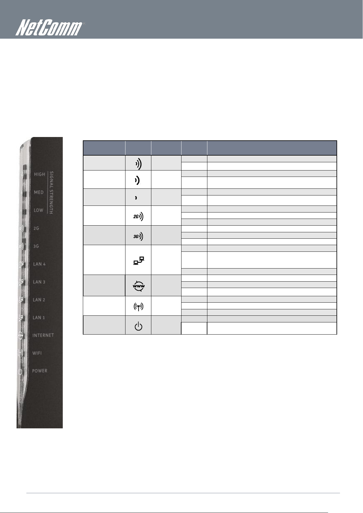
Physical Dimensions and
Indicators
LED Indicators
The 3G42WT has been designed to be placed on a desktop. All of the cables exit from the rear for better organization. The display
is visible on the front of the 3G42WT to provide you with information about network activity and the device status. See below for an
explanation of each of the indicator lights.
LED
ICON COLOUR MODE DEFINITION
High
Med
Low
2G
3G
LAN 1 - 4
Internet
WiFi
Power
Blue
Blue
Blue
Blue
Blue
Blue
Blue
Blue
Blue
On High signal strength
On Medium signal strength
On Low signal strength
Blinking Connecting with 2G network
Off No device connected or connected device is off
On
Blinking Data is being transmitted through the Internet connection
Off Router is powered off
On Router is powered on
Powered device connected to the associated LAN port (includes
devices with Wake-On-LAN capability where a slight voltage is
Page 7
www.netcomm.com.au
7
TELSTRA ULTIMATE GATEWAY – 3G42WT – DC-HSPA+ 42Mbps Wi-Fi Router
NetComm 3G42WT – DC-HSPA+ 42Mbps Wi-Fi Router
YML42T
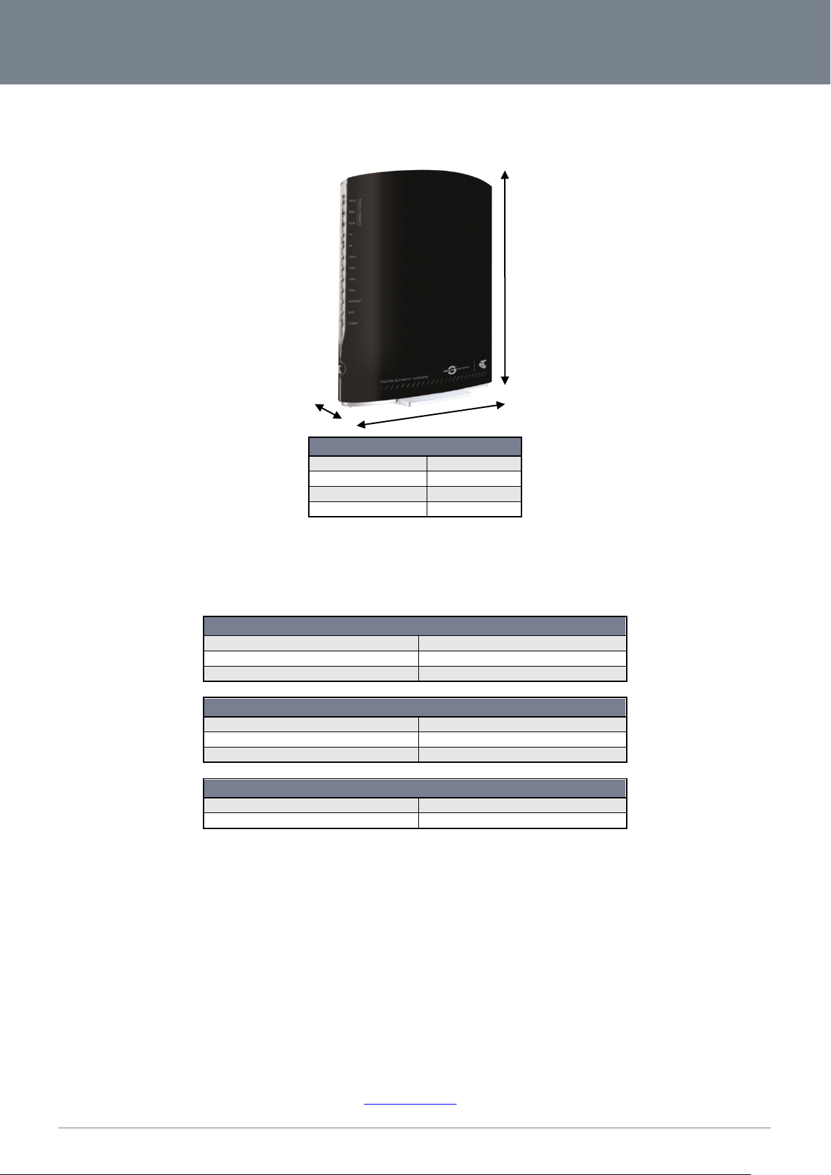
3G42WT
Length
160 mm
Height
195 mm
Width
42 mm
LAN (MANAGEMENT)
Static IP Address:
10.0.0.138
Subnet Mask:
255.255.255.0
Default Gateway:
10.0.0.138
WIRELESS (WI-FI)
SSID:
(Refer to the included Wireless Security Card)
Security:
WPA2-PSK
Security Key:
(Refer to the included Wireless Security Card)
3G42WT WEB INTERFACE ACCESS
Username:
admin
Password:
admin
Physical Dimensions
The following page lists the physical dimensions of the 3G42WT.
Weight 362 grams
3G42WT Default Settings
The following tables list the default settings for the 3G42WT:
Restore Factory Default Settings
Restoring factory defaults will reset the Telstra Ultimate Gateway to its factory default configuration. Occasions may present
themselves where you need to restore the factory defaults on your Telstra Ultimate Gateway such as:
You have lost your username and password and are unable to login to the web configuration page;
You have purchased your Telstra Ultimate Gateway from someone else and need to reconfigure the device to work
with your Next G service;
You are asked to perform a factory reset by support staff.
In order to restore your Telstra Ultimate Gateway to its factory default settings, please follow these steps:
Ensure that your Telstra Ultimate Gateway Router is powered on (for at least 10 seconds);
Use a paper clip or a pencil tip to depress the reset button for ten seconds and release. At this point, the reset is in
progress. Do not power off the unit at this point.
When the indicator lights return to steady blue, the reset is complete. The default settings are now restored. The entire
process takes about 45 seconds to complete.
Once you have reset your Telstra Ultimate Gateway Router to its default settings you will be able to access the
device’s configuration web interface using
http://10.0.0.138 with username ‘admin’ and password ‘admin’.
Page 8
8
NetComm 3G42WT – DC-HSPA+ 42Mbps Wi-Fi Router
YML42T
www.netcomm.com.au
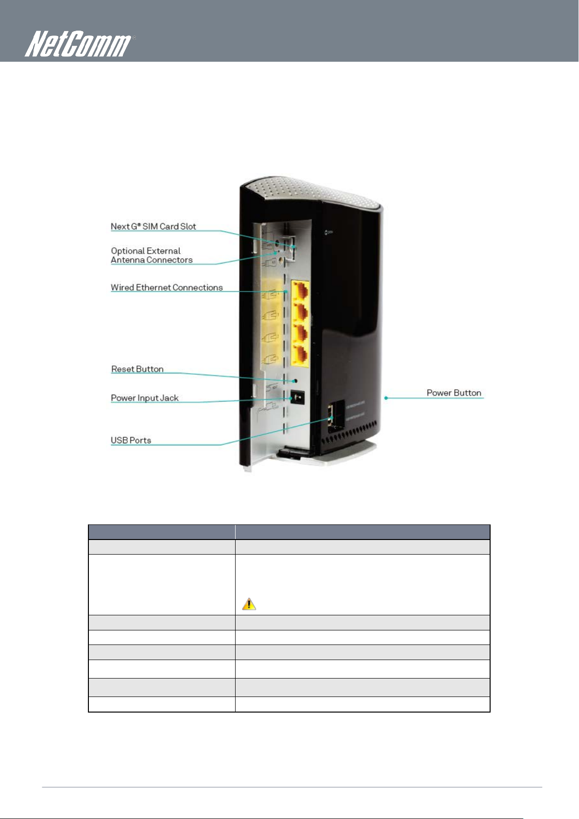
INTERFACE
FUNCTION
the MAIN external antenna connector.
attached devices
attached devices
Integrated Interfaces
The following integrated interfaces are available on the 3G42WT:
Next G SIM Slot Insert an active SIM card here
Optional External Antenna Connectors
Four RJ-45 Ethernet LAN Ports Connect Ethernet based devices here
Reset Button Reset the Router to factory defaults
Power jack for DC power input (12VDC / 1.5A) Connect the power supply here
USB printer / hard drive
USB printer / hard drive
Power button Turn the Router On or Off
You can connect up to 2 external antennas to boost your Next G signal. The
antenna connectors are specially designed and use an accessory cable available
from the NetComm website to facilitate connections to external SMA based
antennas.
Please note: If only connecting a single antenna, ensure it is connected to
Connect a USB based printer or storage device here to share content with
Connect a USB based printer or storage device here to share content with
Page 9

www.netcomm.com.au
9
TELSTRA ULTIMATE GATEWAY – 3G42WT – DC-HSPA+ 42Mbps Wi-Fi Router
NetComm 3G42WT – DC-HSPA+ 42Mbps Wi-Fi Router
YML42T
Safety and Product Care
With reference to unpacking, installation, use and maintenance of your electronic device, the following basic guidelines are
recommended:
Do not use or install this product near water to avoid fire or shock hazard. For example, near a bathtub, kitchen sink,
laundry tub, or near a swimming pool. Also, do not expose the equipment to rain or damp areas (e.g. a wet basement).
Do not connect the power supply cord on elevated surfaces. Allow it to lie freely. There should be no obstructions in its
path and no heavy items should be placed on the cord. In addition, do not walk on, step on or mistreat the cord.
To safeguard the equipment against overheating, make sure that all openings in the unit that offer exposure to air are
unobstructed.
WARNING
Disconnect the power line from the device before servicing.
Transport and Handling
When transporting the 3G42WT, it is recommended to return the product in the original packaging. This ensures the product will not
be damaged.
In the event the product needs to be returned, ensure it is securely packaged with appropriate padding to prevent
damage during courier transport.
Page 10

10
NetComm 3G42WT – DC-HSPA+ 42Mbps Wi-Fi Router
YML42T
www.netcomm.com.au
Installation and Configuration of
the 3G42WT
Placement of your 3G42WT
The wireless connection between your 3G42WT and your Wi-Fi devices will be stronger the closer your connected devices are to
your 3G42WT. Your wireless connection and performance will degrade as the distance between your 3G42WT and connected
devices increases. This may or may not be directly noticeable, and is greatly affected by the individual installation environment.
If you have concerns about your network’s performance that might be related to range or obstruction factors, try moving the
computer to a position between three to five meters from the 3G42WT in order to see if distance is the problem.
Please note: While some of the items listed below can affect network performance, they will not prohibit your wireless
network from functioning; if you are concerned that your network is not operating at its maximum effectiveness, this
checklist may help.
If you experience difficulties connecting wirelessly between your Wi-Fi Devices and your 3G42WT, please try the following steps:
In multi-storey homes, place the 3G42WT on a floor that is as close to the centre of the home as possible. This may
mean placing the 3G42WT on an upper floor.
Try not to place the 3G42WT near a cordless telephone that operates at the same radio frequency as the 3G42WT
(2.4GHz).
Avoid obstacles and interference
Avoid placing your 3G42WT near devices that may emit radio “noise,” such as microwave ovens. Dense objects that can inhibit
wireless communication include:
Refrigerators
Washers and/or dryers
Metal cabinets
Large aquariums
Metallic-based, UV-tinted windows
If your wireless signal seems weak in some spots, make sure that objects such as those listed above are not blocking
the signal’s path (between your devices and the 3G42WT).
Cordless Phones
If the performance of your wireless network is impaired after considering the above issues, and you have a cordless phone:
Try moving cordless phones away from your 3G42WT and your wireless-enabled computers.
Unplug and remove the battery from any cordless phone that operates on the 2.4GHz band (check manufacturer’s
information). If this fixes the problem, your phone may be interfering with the 3G42WT.
If your phone supports channel selection, change the channel on the phone to the farthest channel from your wireless
network. For example, change the phone to channel 1 and move your 3G42WT to channel 11. See your phone’s user
manual for detailed instructions.
If necessary, consider switching to a 900MHz or 5GHz cordless phone.
Choose the “Quietest” Channel for your Wireless Network
In locations where homes or offices are close together, such as apartment buildings or office complexes, there may be wireless
networks nearby that can conflict with your wireless network. Use the Site Survey capabilities found in the Wireless Utility of your
wireless adapter to locate any other wireless networks that are available (see your wireless adapter’s user manual), and switch your
Router and computers to a channel as far away from other networks as possible.
Experiment with more than one of the available channels, in order to find the clearest connection and avoid interference from
neighbouring cordless phones or other wireless devices.
Page 11

www.netcomm.com.au
11
TELSTRA ULTIMATE GATEWAY – 3G42WT – DC-HSPA+ 42Mbps Wi-Fi Router
NetComm 3G42WT – DC-HSPA+ 42Mbps Wi-Fi Router
YML42T
Hardware installation
1. Connect the power adapter to the Power socket on the back of the 3G42WT.
2. Plug the power adapter into the wall socket and switch on the power.
3. Wait approximately 60 seconds for the 3G42WT to power up.
Connecting via a cable
1. Connect the yellow Ethernet cable provided to one of the ports marked ‘LAN’ at the back of the 3G42WT.
2. Connect the other end of the yellow Ethernet cable to your computer.
3. Wait approximately 30 seconds for the connection to establish.
4. Open your Web browser, and enter http://10.0.0.138 into the address bar and press enter.
5. Follow the steps on the next page to set up your 3G42WT.
Connecting wirelessly
1. Ensure Wi-Fi is enabled on your device (computer/laptop/Smartphone).
2. Scan for wireless networks in your area and connect to the network name that matches the Wireless network name
configured on the 3G42WT.
Please note: Refer to the included Wireless Security Card to check your default Wireless Network Name (SSID)
3. When prompted for your wireless security settings, enter the Wireless security key configured on the 3G42WT.
Please note: Refer to the included Wireless Security Card to check your default Wireless Security Key.
4. Wait approximately 30 seconds for the connection to establish.
5. Open your Web browser, and enter http://10.0.0.138 into the address bar and press enter.
6. Follow the steps on the next page to set up your 3G42WT.
Page 12
12
NetComm 3G42WT – DC-HSPA+ 42Mbps Wi-Fi Router
YML42T
www.netcomm.com.au
Quick Setup
Setup Procedure
These steps explain how to quickly setup your Telstra Ultimate Gateway:
1. Insert your SIM card (until you hear a click) into the USIM slot on the rear of the Router.
2. Connect the yellow Ethernet cable to one of the yellow LAN ports found at the back of the Router.
3. Connect the other end of the yellow networking cable to the Ethernet port on your computer.
4. Connect the power adapter to the Power socket on the back of the Router.
5. Plug the power adapter into a wall socket and press the power button into the ON position.
Select one of the following methods to configure your 3G42WT:
USB Setup Wizard
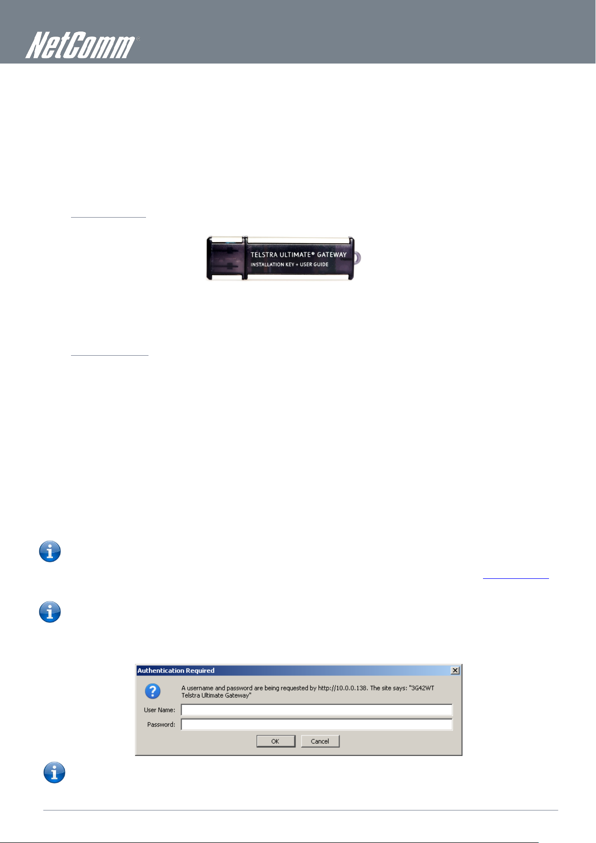
6. Plug in the supplied USB key (as shown below) and run the setup wizard.
7. Follow the steps displayed. These steps will configure your 3G42WT and configure it to connect to the Internet.
8. The 3G42WT will then attempt to connect to the Internet with the setup information you entered.
-OR-
Web User Interface
6. Configure the Router through the Web User Interface (WUI) using the steps on the following pages.
7. Save the Router configuration and reboot.
8. The 3G42WT will now attempt to connect to the Internet with the configuration settings you entered.
Web User Interface
What can you do from here?
By logging into the web user interface, you are able to configure your Telstra Ultimate Gateway with a wide array of basic and
advanced settings. From setting wireless security, to backing up your routers settings, uploading new firmware and setting parental
controls, the web user interface is a handy tool for personalizing your device to maximize its potential. Read on for a more advanced
description on all elements of the web user interface.
Logging into the web user interface
To login to the web user interface, follow the steps below:
Please note: The default settings can be found in the Default Settings section on page 7.
1. Open a web browser and enter the default IP address for the Router in the web address field. In this case
Please note: For local administration (i.e. LAN access), the PC running the browser must be attached to the Ethernet port of
the router though not necessarily directly to the device. For remote access, use the WAN IP address shown on the WUI
Homepage screen and login with remote username and password.
2. A dialog box will appear, as shown below. Enter the default username and password ‘admin’ (without the quotes). Click OK
to continue.
http://10.0.0.138
Please note: The login password can be changed later (see Access Control > Passwords)
Page 13

www.netcomm.com.au
13
TELSTRA ULTIMATE GATEWAY – 3G42WT – DC-HSPA+ 42Mbps Wi-Fi Router
NetComm 3G42WT – DC-HSPA+ 42Mbps Wi-Fi Router
YML42T
The radio access technique currently used to enable internet access. It can be HSUPA, HSDPA, UMTS, EDGE,
GPRS or Disconnected.
The mobile network (UMTS) signal quality available at the device location. This signal quality affects the
performance of the unit. If two or more bars are green, the connection is usually acceptable.
Basic
Home
The web user interface (WUI) is divided into two window panels, the main menu (on the top) and the display screen (on the bottom).
The main menu has the following options: Basic, Next G Settings, Wireless, Management, Advanced and Status.
Selecting one of these options will open a submenu with more options. Basic is discussed below while subsequent chapters
introduce the other main menu selections.
Please note: The menu options available within the web user interface are based upon the device configuration and user
privileges (i.e. local or remote).
The following table provides further details about the listed items:
PARAMETER DEFINITION
Model Name Model number of your device
Board ID The unique number of the board inside your device
Gateway Firmware Version The version of firmware currently being used on your device
Web UI Version The current version of the Web UI interface
Bootloader (CFE) Version The version of the bootloader
Wireless Driver Version The current version of wireless driver being used by your device
MAC Address The MAC address of the network interface
Serial Number The serial number of the unit
System Up Time The time the device has been operational since the last reboot
Network The name of your 3G network
Link The status of your 3G connection
Mode
Signal Strength
SIM Info Shows the SIM card status on the device.
Connection Up Time The length of time your device has been connected to your NextG service
LAN IP Address Shows the IP address for LAN interface.
WAN IP Address Shows the IP address for WAN interface.
Primary DNS Server Shows the IP address of the primary DNS server.
Secondary DNS Server Shows the IP address of the secondary DNS server.
Date/Time The time according to the device’s internal clock
Page 14
14
NetComm 3G42WT – DC-HSPA+ 42Mbps Wi-Fi Router
YML42T
www.netcomm.com.au
Next G Settings
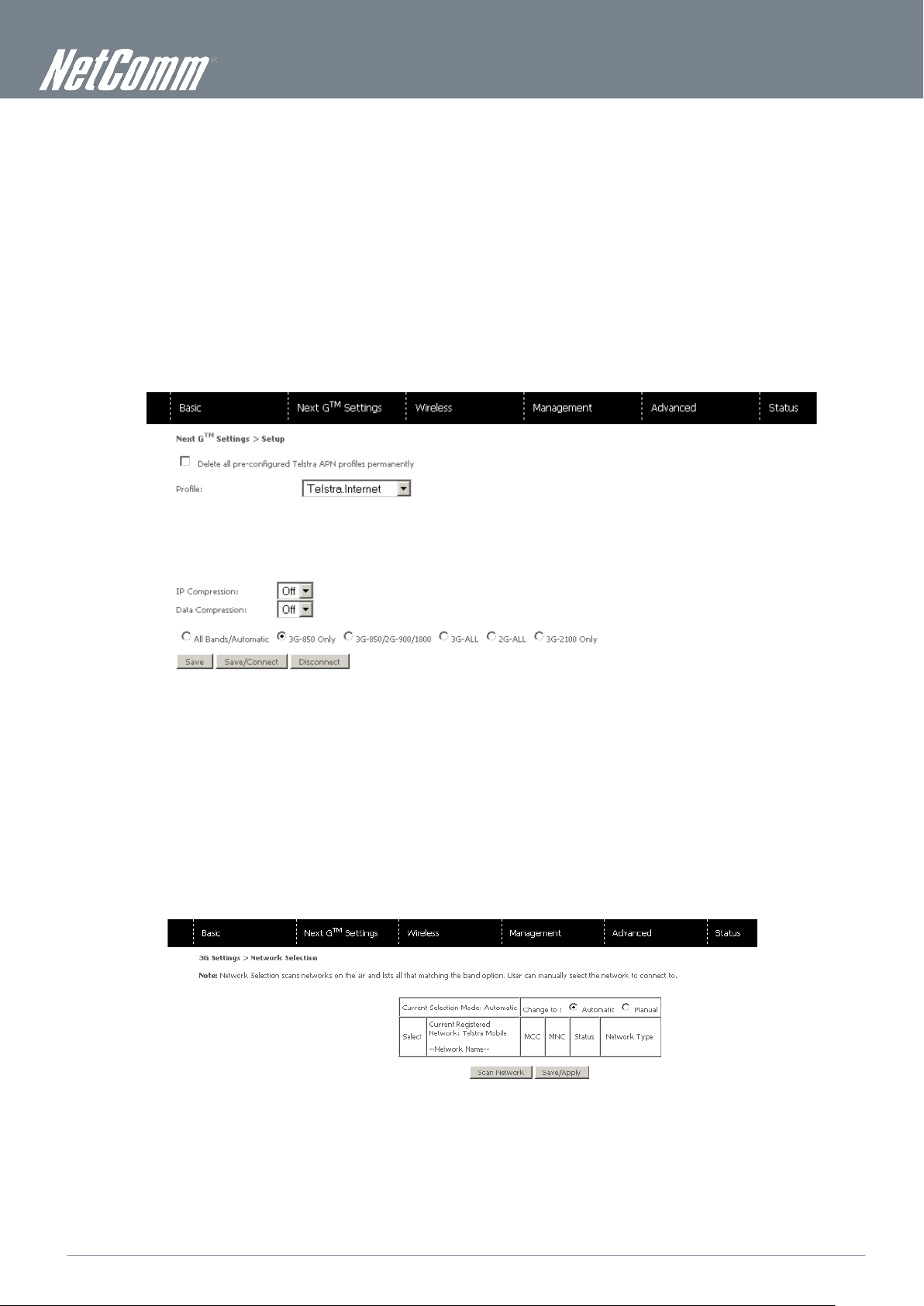
Setup
This page allows you to select your Next G service settings according to predefined or custom profiles. Setup instructions are
provided in the following sections for your assistance.
1. If your SIM card is not inserted into the Router, then do so now.
2. Select the appropriate 3G Settings Profile. You can select from the following pre-configured profiles:
Telstra.Bigpond
Telstra.Internet
Telstra.Datapack
Alternatively, enter a custom connection profile by selecting the “Custom APN” option, and then entering the details as supplied by
your 3G provider.
3. Select to turn IP compression and Data compression to be On or Off. If you are unsure or have no preference, leave it as the
default value.
4. Enter the MTU rate. If you are unsure or have no preference, leave it as the default value
5. Click Save to save the new settings.
6. Press the Connect button to connect to Internet. The Device Info for the 3G network status box in the WUI Basic screen
should indicate an active connection.
Network Selection
The Network Selection page enables you to scan for available Next G services in your area and manually select a specific service to
use.
The 3G42WT will automatically select the network with the best signal strength to use, however if required, select “Manual” and
click the “Scan Network” button to have the 3G42WT scan for available services.
After selecting the appropriate service to use, click
Save/Apply.
Page 15
www.netcomm.com.au
15
TELSTRA ULTIMATE GATEWAY – 3G42WT – DC-HSPA+ 42Mbps Wi-Fi Router
NetComm 3G42WT – DC-HSPA+ 42Mbps Wi-Fi Router
YML42T
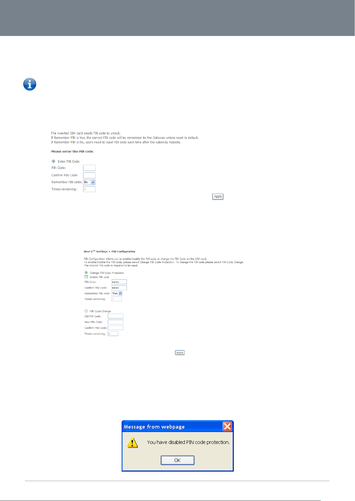
PIN Configuration
This screen allows for changes to the 3G SIM card PIN code protection settings.
Please note: If you have entered the incorrect PIN 3 times, your SIM card will be locked for your security. Please call Telstra
for assistance if this occurs.
PIN Code Protection
PIN code protection prevents the use of a SIM card by unauthorized persons. To use the 3G internet service with this router
however, the PIN code protection should be disabled. If the SIM card inserted into the router is locked with a PIN code, the web
user interface will display the following screen after first login.
Please input the PIN code, select Remember PIN code as Yes and click Apply.
PIN Lock Off
If you wish to always connect to the Internet using a PIN locked SIM card, you should first turn PIN code protection off. Please click
on PIN Configuration from the menu.
Select Change PIN Code Protection. Un-tick Enable PIN Lock and enter the PIN code twice. Please keep in mind you only have 3
attempts before your SIM card is locked.
Times remaining shows how many attempts are left. (Contact Telstra if you require assistance with your PIN code).
The
Click Apply.
The following dialog box should now appear.
Page 16

16
NetComm 3G42WT – DC-HSPA+ 42Mbps Wi-Fi Router
YML42T
www.netcomm.com.au
PIN Lock On
After you are finished using your SIM card for Internet access, you may wish to lock the SIM card again. In this case, first go to the
PIN configuration screen, as shown below.
Select Change PIN Code Protection. Tick Enable PIN Lock, enter the PIN code twice. You can set Remember PIN code to yes so
you don’t need to input the PIN code every time when the gateway turns on with this SIM inserted. Then click
After you do so, the following dialog box should appear.
Apply.
You can now return your SIM card to your cellular phone or other mobile device.
PIN Code Change
If you wish to change your PIN code for greater security, go to the previous section and follow the procedure listed under
On. After locking the SIM card, select PIN Code Change and enter your old and new PIN codes in the fields provided. Keep in mind
you only have 3 attempts before your SIM card is locked. The
you require assistance. Afterwards, click
Apply to activate the change.
Times remaining shows how many attempts left. Contact Mobily if
PIN Lock
If you forget to turn on PIN lock protection before changing your PIN, you will see this dialog box as a helpful reminder.
If your PIN code change request was successful the following dialog box will display.
Page 17

www.netcomm.com.au
17
TELSTRA ULTIMATE GATEWAY – 3G42WT – DC-HSPA+ 42Mbps Wi-Fi Router
NetComm 3G42WT – DC-HSPA+ 42Mbps Wi-Fi Router
YML42T
Wireless
Setup
The WiFi submenu provides access to the Wireless Local Area Network (WLAN) configuration settings including:
Wireless network name (SSID)
Channel restrictions (based on country)
Security
Access point or bridging behaviour
Station information
This screen allows you to configure basic features of the wireless LAN interface. You can enable or disable the wireless LAN
interface, hide the network from active scans, set the wireless network name (also known as the SSID) and restrict the channel set
based on country requirements. The Wireless Guest Network function adds extra networking security when connecting to remote
hosts.
PARAMETER DEFINITION
Enable WiFi A checkbox that enables or disables the wireless LAN interface. The default is Enable WiFi.
Enable SSID Broadcast
Clients Isolation
SSID
[1-32 characters]
BSSID
Country
Max Clients The maximum number of wireless clients allowed to connect to the wireless network.
Wireless Guest Network
Click
Apply/Save to save the new Wi-Fi configuration.
Deselect Enable SSID Broadcast to protect the access point from detection by wireless network scans.
To check AP status in Windows XP, open Network Connections from the Start Menu and select View Available
Network Connections. If the access point is hidden, it will not be listed there. To connect a client to a hidden
access point, the station must add the access point manually to its wireless configuration.
1. Prevents clients PC from seeing one another in My Network Places or Network Neighborhood.
2. Prevents one wireless client communicating with another wireless client.
Sets the wireless network name. SSID stands for Service Set Identifier. All stations must be configured with the
correct SSID to access the WLAN. If the SSID does not match, that user will not be granted access.
The naming conventions are: Minimum number of characters: 1, maximum number of characters: 32.
The BSSID is a 48bit identity used to identify a particular BSS (Basic Service Set) within an area. In
Infrastructure BSS networks, the BSSID is the MAC (Medium Access Control) address of the AP (Access Point)
and in Independent BSS or ad hoc networks, the BSSID is generated randomly.
A drop-down menu that permits worldwide and specific national settings. Each county listed in the menu
enforces specific regulations limiting channel range.
This router supports multiple SSIDs called Guest SSIDs or Virtual Access Points. To enable one or more Guest
SSIDs select the radio buttons under the Enable heading. To hide a Guest SSID, select its radio button under
the Hidden heading.
Do the same for Isolate Client. For a description of this function, see the entry for “Client Isolation” in this table.
Similarly, for Max Clients and BSSID headings, consult the matching entries in this table.
NOTE: Remote wireless hosts are unable to scan Guest SSIDs.
Page 18

18
NetComm 3G42WT – DC-HSPA+ 42Mbps Wi-Fi Router
YML42T
www.netcomm.com.au
The Telstra Ultimate Gateway is able to handle multiple wireless networks. The pull down menu enables you
to select which wireless network the security settings will be applied to.
A new type of wireless security that gives a more secure network when compared to WEP. The security key
and numbers. This is the default wireless security in use on the router.
Security
This router includes a number of options to help provide a secure connection to the Wi-Fi Network.
Security features include:
WEP / WPA / WPA2 data encryption
MAC address IP filtering
You can authenticate or encrypt your service on the Wi-Fi Protected Access algorithm, which provides protection against
unauthorized access such as eavesdropping.
The following screen appears when Security is selected. The Security page allows you to configure security features of your router’s
WLAN interface. You can set the network authentication method, select data encryption, specify whether a network key is required
to authenticate to this wireless network and specify the encryption strength.
Click Apply/Save to configure the wireless security options:
PARAMETER DEFINITION
Select SSID
Network Authentication
WEP Encryption
WPA-PSK / WPA2-PSK
WPA
Encryption Strength The strength/length of your wireless security key.
Current Network Key The current network key that is active. You have the choice of setting up to 4 different wireless security keys
Network Key 1 The value of network key 1.
Network Key 2 The value of network key 2
Network Key 3 The value of network key 3
Network key 4 The value of network key 4
This option is used for authentication to the wireless network. Each authentication type has its own settings.
For example, selecting 802.1X authentication will reveal the RADIUS Server IP address, Port
and key fields.
This option indicates whether data sent over the network is encrypted.
The same network key is used for data encryption and network authentication. Whilst four network keys can
be defined, only one can be used at any one time.
needs to be more than 8 characters and less than 63 characters and it can be any combination of letters
WPA (Wi-Fi Protected Access) is suitable for enterprise applications. It must be used in conjunction with an
authentication server such as RADIUS to provide centralized access control and management.
Page 19

www.netcomm.com.au
19
TELSTRA ULTIMATE GATEWAY – 3G42WT – DC-HSPA+ 42Mbps Wi-Fi Router
NetComm 3G42WT – DC-HSPA+ 42Mbps Wi-Fi Router
YML42T
Channel
Allows selection of a specific channel (1-14) or Auto mode.
(EWC)
Turn off for maximized throughput
Threshold too low may result in poor performance.
disables the RTS Threshold.
The default is 1.
station needs the beacon interval to know when to wake up to receive the beacon.
been designed to improve wireless network efficiency. Default is disabled
Configuration
This screen allows you to control the advanced features of the Wireless Local Area Network (WLAN) interface including:
Select the channel you wish to operate from
Force the transmission speed
Set the fragmentation threshold
Set the wake-up interval for clients in power-save mode
Set the beacon interval for the access point
Apply/Save to set the advanced wireless configuration.
Click
PARAMETER DEFINITION
Band The frequency of the wireless network. 2.4GHz is standard.
Auto Channel Timer The Auto Channel times the length it takes to scan in minutes.
802.11n/EWC
Bandwidth
Control Sideband This is available for 40MHz. Drop-down menu allows selecting upper sideband or lower sideband
802.11n Rate
802.11n Protection
Support 802.11n Client Only The option to provide wireless Internet access only to clients who are operating at 802.11n speeds
54g Rate
Multicast rate Setting for multicast packet transmission rate. (1-54 Mbps)
Basic Rate Sets basic transmission rate.
Fragment Threshold
RTS Threshold
An equipment interoperability standard setting based on IEEE 802.11n Draft 2.0 and Enhanced Wireless Consortium
The drop-down menu specifies the following bandwidth: 20MHz in 2.4G Band and 40 MHz in 5G Band, 20MHz in both
bands and 40MHz in both bands
Drop-down menu specifies the following fixed rates. The maximum rate for bandwidth, 20MHz, is 130Mbps and the
maximum bandwidth, 40MHz, is 270Mbps
Turn on for greater security
In Auto (default) mode, your Router uses the maximum data rate and lowers the data rate dependent on the signal
strength. The appropriate setting is dependent on signal strength. Other rates are discrete values between 1 to 54 Mbps.
A threshold (in bytes) determines whether packets will be fragmented and at what size. Packets that exceed the
fragmentation threshold of an 802.11 WLAN will be split into smaller units suitable for the circuit size. Packets smaller
than the specified fragmentation threshold value however are not fragmented.
Values between 256 and 2346 can be entered but should remain at a default setting of 2346. Setting the Fragmentation
Request To Send (RTS) specifies the packet size that exceeds the specified RTS threshold, which then triggers the
RTS/CTS mechanism. Smaller packets are sent without using RTS/CTS. The default setting of 2347 (max length) will
Delivery Traffic Indication Message (DTIM) is also known as Beacon Rate. The entry range is a value between 1 and
65535. A DTIM is a countdown variable that informs clients of the next window for listening to broadcast and multicast
DTIM Interval
Beacon Interval
Global Max Clients Here you have the option of setting the limit of the number of clients who can connect to your wireless network
Xpress Technology
Transmit Power The option of decreasing the transmitting power of y our wireless signal
messages. When the AP has buffered broadcast or multicast messages for associated clients, it sends the next DTIM
with a DTIM Interval value. AP Clients hear the beacons and awaken to receive the broadcast and multicast messages.
The amount of time between beacon transmissions in is milliseconds. The default is 100 ms and the acceptable range is
1 – 65535. The beacon transmissions identify the presence of an access point. By default, network devices passively
scan all RF channels listening for beacons coming from access points. Before a station enters power save mode, the
Broadcom’s Xpress™ Technology is compliant with draft specifications of two planned wireless industry standards. It has
Page 20

20
NetComm 3G42WT – DC-HSPA+ 42Mbps Wi-Fi Router
YML42T
www.netcomm.com.au
Disabled – Disables MAC filtering
Allow
Deny
Lists the MAC addresses subject to the MAC Restrict Mode. The Add button prompts an entry field
where xx are hexadecimal numbers. A maximum of 60 MAC addresses can be added.
MAC Filter
This screen appears when Media Access Control (MAC) Filter is selected. This option allows access to be restricted based upon the
unique 48-bit MAC address.
To add a MAC Address filter, click the
To delete a filter, select it from the table below and click the Remove button.
Add button shown below.
PARAMETER DEFINITION
– Permits access for the specified MAC addresses.
MAC Restrict Mode
MAC Address
Please note: Add a wireless device’s MAC address before clicking the Allow radio button or else
you will need to connect to the Router’s web user interface using the supplied yellow Ethernet cable
and add the wireless device’s MAC address.
– Rejects access for the specified MAC addresses
that requires you type in a MAC address in a two-character, 6-byte convention: xx:xx:xx:xx:xx:xx
Enter the MAC address on the screen below and click Apply/Save.
Page 21

www.netcomm.com.au
21
TELSTRA ULTIMATE GATEWAY – 3G42WT – DC-HSPA+ 42Mbps Wi-Fi Router
NetComm 3G42WT – DC-HSPA+ 42Mbps Wi-Fi Router
YML42T
Wireless Bridge
Access Point
Access Point
Disabled
Refresh
Wireless Bridge
The following screen appears when selecting Wireless Bridge, and goes into a detailed explanation of how to configure wireless
bridge features of the wireless LAN interface.
Click
Apply/Save to implement new configuration settings.
PARAMETER DEFINITION
AP Mode
Bridge Restrict
Selecting
selecting Access Point enables AP functionality. In
still be available and wireless stations will be able to associate to the AP.
Selecting
bridge will be granted access. Selecting Enabled or Enabled (Scan) allows wireless bridge restriction.
Only those bridges selected in Remote Bridges will be granted access. Click
station list when Bridge Restrict is enabled.
(Wireless Distribution System) disables
mode, wireless bridge functionality will
in Bridge Restrict disables Wireless Bridge restriction, which means that any wireless
(AP) functionality while
to update the
Station Info
The following screen appears when you select Station Info, and shows authenticated wireless stations and their status.
Click the Refresh button to update the list of stations in the WLAN.
PARAMETER DEFINITION
MAC The MAC address of any connected client
Associated
Authorized Lists those devices with authorized access.
SSID The SSID of your wireless network
Interface The wireless interface being used to connect
Lists all the stations that are associated with the Access Point, along with the amount of time since
packets were transferred to and from each station. If a station is idle for too long, it is removed from
this list.
Page 22

22
NetComm 3G42WT – DC-HSPA+ 42Mbps Wi-Fi Router
YML42T
www.netcomm.com.au
Management
Device Settings
The Device Settings screens allow you to backup, retrieve and restore the default settings of your Router. It also provides a function
for you to update your Routers firmware.
Backup
The following screen appears when Backup is selected. Click Backup Settings to save the current configuration settings.
You will be prompted to choose the location on your PC to save the backed up configuration file to.
Update
The following screen appears when selecting Update from the submenu. By clicking on the Browse button, you can locate a
previously saved backup configuration file as the configuration backup file to use to update your Connect routers configuration.
Click on the
Update settings to load it.
Restore Default
The following screen appears when selecting Restore Default. By clicking on Restore Default Settings, you can restore your Routers
default firmware settings. To restore system settings, reboot your Router.
Please note: The default settings can be found in the Default Settings section on page 7.
Once you have selected the Restore Default Settings button, follow the on screen steps, close the window and wait 2 minutes
before reopening your browser. If required, reconfigure your PCs IP address to match your new configuration (see the TCP/IP
Settings section for details).
After a successful reboot, the browser will return to the Device Info screen. If the browser does not refresh to the default screen,
close and restart the browser and then enter
Please note: The Restore Default function has the same effect as the reset button. If the reset button is continuously pushed
for more than 5 seconds (and not more than 12 seconds), the boot loader will erase the configuration settings saved on
flash memory.
http://10.0.0.138 into the address bar at the top of your browser window.
Page 23

www.netcomm.com.au
23
TELSTRA ULTIMATE GATEWAY – 3G42WT – DC-HSPA+ 42Mbps Wi-Fi Router
NetComm 3G42WT – DC-HSPA+ 42Mbps Wi-Fi Router
YML42T
Update Firmware
The following screen appears when selecting Update Firmware. By following this screens steps, you can update your Routers
firmware. Manual device upgrades from a locally stored file can also be performed using the following screen.
1. Obtain an updated software image file
2. Enter the path and filename of the firmware image file in the Software File Name field or click Browse to locate the image file.
3. Click Update Software to upload and install the file.
Please note: The update process will take about 2 minutes to complete. The Router will reboot and the browser window
will refresh to the default screen upon successful installation. It is recommended that you compare the Software Version at
the top of the Basic screen (WUI homepage) with the firmware version installed, to confirm the installation was successful.
Access Control
The Access Control option found in the Management drop down menu, configures access related parameters in the following three
areas:
Services
Passwords
Save/Reboot
Access Control is used to control local and remote management settings for your Router.
Services
The Service Control List (SCL) allows you to enable or disable your Local Area Network (LAN) or Wide Area Network (WAN) services
by ticking the checkbox as illustrated below. The following access services are available: FTP, HTTP, ICMP, SNMP, SSH, TELNET,
and TFTP. Click Apply/Save to continue.
Page 24

24
NetComm 3G42WT – DC-HSPA+ 42Mbps Wi-Fi Router
YML42T
www.netcomm.com.au
Passwords
The Passwords option configures your Web UI account access password for your Router. Access to the device is limited to the
following three user accounts:
admin is to be used for local unrestricted access control
support is to be used for remote maintenance of the device
user is to be used to view information and update device firmware
Use the fields illustrated in the screen below to change or create your password. Passwords must be 16 characters or less with no
spaces. Click
Apply/Save to continue.
SNMP
The Simple Network Management Protocol (SNMP) allows a network administrator to monitor a network by retrieving settings on
remote network devices. To do this, the administrator typically runs an SNMP management station program such as MIB browser
on a local host to obtain information from the SNMP agent, in this case the 3G42WT (if SNMP is enabled). An SNMP ‘community’
performs the function of authenticating SNMP traffic. A ‘community name’ acts as a password that is typically shared among SNMP
agents and managers.
PARAMETER DEFINITION
Read Community Read device settings
Set Community Read and change device settings
System Name Default = 3G42WT
System Location User defined value
System Contact User defined value
Trap Manager IP IP address of admin machine
Click Apply/Save to save the new SNMP settings.
Page 25

www.netcomm.com.au
25
TELSTRA ULTIMATE GATEWAY – 3G42WT – DC-HSPA+ 42Mbps Wi-Fi Router
NetComm 3G42WT – DC-HSPA+ 42Mbps Wi-Fi Router
YML42T
SNTP
This screen allows you to configure the time settings of your Router.
PARAMETER DEFINITION
First NTP timeserver Select the required server.
Second NTP timeserver Select second timeserver, if required.
Time zone offset Select the local time zone.
Please note: SNTP must be activated to use Parental Control .
Click Apply/Save to save the new SNTP settings.
Save/Reboot
This function saves the current configuration settings and reboots your Router.
Please note: It may be necessary to reconfigure your TCP/IP settings to adjust for the new configuration. For example, if
you disable the Dynamic Host Configuration Protocol (DHCP) server you will need to apply Static IP settings.
Please note: If you lose all access to your web user interface, simply press the reset button on the rear panel for 5-7
seconds to restore default settings.
Click Save/Reboot to reboot your Router.
Page 26

26
NetComm 3G42WT – DC-HSPA+ 42Mbps Wi-Fi Router
YML42T
www.netcomm.com.au
Standard Mode
Blocking Mode
Advanced Settings
LAN
This screen allows you to configure the Local Area Network (LAN) interface on your Router.
See the field descriptions below for more details.
PARAMETER DEFINITION
IP Address Enter the IP address for the LAN interface
Subnet Mask Enter the subnet mask for the LAN interface
Enable by ticking the box
Enable IGMP Snooping
Enable LAN side Firewall Select to enable the Firewall on the LAN side
Disable DHCP Server Disables the DHCP server. Only to be done if Static IP address is set up
Enable DHCP Server
Enable DHCP Server Relay
Configure the second IP Address
and Subnet Mask for LAN Interface
multicast group.
subscriptions to a multicast group, it will not fl ood to the bridge ports.
Select Enable DHCP server and enter your starting and ending IP addresses and the lease time. This setting
configures the router to automatically assign IP, default gateway and DNS server addresses to every DHCP
client on your LAN
To relay DHCP requests from the subnet with no DHCP server on it to a DHCP server on other subnets. DHCP
Server Relay is disabled by default. To access enable DHCP relay, please un-tick NAT enable first, that means to
disable NAT first, and then press save button.
Configure a second IP address by ticking the checkbox shown below and enter the following information:
Enter the secondary IP address for the LAN interface.
Enter the secondary subnet mask for the LAN interface.
: In standard mode, multicast traffic will flood to all bridge ports when no client subscribes to a
: In blocking mode, the multicast data traffic will be blocked. When there are no client
Click Apply/Save to save your new LAN settings.
Page 27

www.netcomm.com.au
27
TELSTRA ULTIMATE GATEWAY – 3G42WT – DC-HSPA+ 42Mbps Wi-Fi Router
NetComm 3G42WT – DC-HSPA+ 42Mbps Wi-Fi Router
YML42T
Enter the starting external port number (when you select Custom Server). When a service is selected the port
ranges are automatically configured.
Enter the ending external port number (when you select Custom Server). When a service is selected the port
ranges are automatically configured.
Enter the internal port starting number (when you select Custom Server). When a service is selected the port
ranges are automatically configured
Enter the internal port ending number (when you select Custom Server). When a service is selected the port
NAT
Port Forwarding
Port Forwarding allows you to direct incoming traffic from the Internet side (identified by Protocol and External port) to the internal
server with a private IP address on the LAN side. The Internal port is required only if the external port needs to be converted to a
different port number used by the server on the LAN side. A maximum of 32 entries can be configured.
To add a Virtual Server, click Add. The following screen will display.
PARAMETER DEFINITION
Select a Service or Custom Server User should select the service from the list or create a custom server and enter a name for the server
Server IP Address Enter the IP address for the server.
External Port Start
External Port End
Protocol User can select from: TCP, TCP/UDP or UDP.
Internal Port Start
Internal Port End
ranges are automatically configured.
Click Apply/Save to save the configured Virtual Server settings.
Page 28

28
NetComm 3G42WT – DC-HSPA+ 42Mbps Wi-Fi Router
YML42T
www.netcomm.com.au
Select an Application or Custom
Application
Enter the starting trigger port number (when you select custom application). When an application is selected, the
port ranges are automatically configured.
Enter the ending trigger port number (when you select custom application). When an application is selected, the
port ranges are automatically configured.
Enter the starting open port number (when you select custom application). When an application is selected, the
port ranges are automatically configured.
Enter the ending open port number (when you select custom application). When an application is selected, the
port ranges are automatically configured.
Port Triggering
Some applications require specific ports in the Router’s firewall to be open for access by remote parties. Port Triggering opens up
the ‘Open Ports’ in the firewall when an application on the LAN initiates a TCP/UDP connection to a remote party using the
‘Triggering Ports’.
The Router allows the remote party from the WAN side to establish new connections back to the application on the LAN side using
the ‘Open Ports’. A maximum 32 entries can be configured.
To add a Trigger Port, simply click Add. The following will be displayed.
PARAMETER DEFINITION
User should select the application from the list or the user can enter the name of their choice.
Trigger Port Start
Trigger Port End
Trigger Protocol TCP, TCP/UDP or UDP.
Open Port Start
Open Port End
Open Protocol TCP, TCP/UDP or UDP
Click Apply/Save to save the configured Port Trigger settings.
Page 29

www.netcomm.com.au
29
TELSTRA ULTIMATE GATEWAY – 3G42WT – DC-HSPA+ 42Mbps Wi-Fi Router
NetComm 3G42WT – DC-HSPA+ 42Mbps Wi-Fi Router
YML42T
DMZ Host
Your Router will forward IP packets from the Wide Area Network (WAN) that do not belong to any of the applications configured in
the Virtual Servers table to the DMZ host computer.
Enter the computer’s IP address and click
Clear the IP address field and click Save/Apply to deactivate the DMZ host.
Save/Apply to activate the DMZ host.
Security
IP Filtering
The IP Filtering screen sets filter rules that limit incoming and outgoing IP traffic. Multiple filter rules can be set with at least one
limiting condition. All conditions must be fulfilled before individual IP packets can pass the filter.
Outgoing IP Filter
The default setting for Outgoing traffic is ACCEPTED. Under this condition, all outgoing IP packets that match the filter rules will be
BLOCKED.
To add a filtering rule, click Add. The following screen will display.
PARAMETER DEFINITION
Filter Name The filter rule label
Protocol TCP, TCP/UDP, UDP or ICMP Source IP address
Source IP address Enter source IP address Source Subnet Mask
Destination IP address Enter source subnet mask
Source Port (port or port:port) Enter source port number or port range
Destination IP address Enter destination IP address
Destination Subnet Mask Destination Subnet Mask
Destination port (port or port:port) Enter destination port number or range
Click Apply/Save to save and activate the filter.
Page 30

30
NetComm 3G42WT – DC-HSPA+ 42Mbps Wi-Fi Router
YML42T
www.netcomm.com.au
Incoming IP Filter
The default setting for all Incoming traffic is BLOCKED. Under this condition only those incoming IP packets that match the filter
rules will be
To add a filtering rule, click Add. The following screen will display.
ACCEPTED.
Please note: Refer to the Outgoing IP Filter table for field descriptions. The configuration steps are identical.
Click Apply/Save to save and activate the filter.
Parental Control
The Parental Control feature allows you to take advanced measures to ensure the computers connected to the LAN are used only
when and how you decide.
Time Restriction
This Parental Control allows you to restrict access from a Local Area Network (LAN) to an outside network through the Router on
selected days at certain times. Make sure to activate the Internet Time server synchronization as described in section 8.3 SNTP, so
that the scheduled times match your local time.
Click Add to display the following screen.
Page 31

www.netcomm.com.au
31
TELSTRA ULTIMATE GATEWAY – 3G42WT – DC-HSPA+ 42Mbps Wi-Fi Router
NetComm 3G42WT – DC-HSPA+ 42Mbps Wi-Fi Router
YML42T
See instructions below and click Apply/Save to apply the settings.
PARAMETER DEFINITION
Policy Name A user-defined label for this restriction
Browser’s MAC Address MAC address of the PC running the browser
Other MAC Address MAC address of another LAN device
Days of the week The days the restrictions apply
Start Blocking Time The time the restrictions start
End Blocking Time The time the restrictions end
URL filter
With the URL filter, you are able to add certain websites or URLs to a safe or blocked list. This will provide you added security to
ensure any website you deem unsuitable will not be able to be seen by anyone who is accessing the Internet via the Telstra Ultimate
Gateway.
Simply check
To Block or To Allow and then click Add to enter the URL you wish added to a list
Click Add and then type the URL you wish to block into the URL Address field it in and click Apply/Save.
Please note: You can also enter a port number if required. Enter this into the Port Number field.
Page 32

32
NetComm 3G42WT – DC-HSPA+ 42Mbps Wi-Fi Router
YML42T
www.netcomm.com.au
Routing
Static Route and Dynamic Route settings can be found in the Routing link.
Static route
The Static Route screen displays the configured static routes.
Click the
Click Add to display the following screen.
Add or Remove buttons to change settings.
Enter Destination Network Address, Subnet Mask. Then click Apply/Save to add the entry to the routing table.
Dynamic route
To activate this option, select the Enabled radio button for Global RIP Mode.
To configure an individual interface, select the desired RIP version and operation, followed by placing a check in the Enabled
checkbox for that interface. Click
Apply/Save to save the configuration and to start or stop dynamic routing.
Page 33

www.netcomm.com.au
33
TELSTRA ULTIMATE GATEWAY – 3G42WT – DC-HSPA+ 42Mbps Wi-Fi Router
NetComm 3G42WT – DC-HSPA+ 42Mbps Wi-Fi Router
YML42T
DNS
DNS server
This page allows you to enable automatic DNS from the ISP or specify your own DNS server address manually.
Dynamic DNS
The Dynamic DNS service allows a dynamic IP address to be aliased to a static hostname in any of a selection of domains, allowing
the router to be more easily accessed from various locations on the Internet.
Please note: The Add/Remove buttons will only be displayed if the router has been assigned an IP address from the
remote server.
To add a dynamic DNS service, click
Add and this screen will display.
PARAMETER DEFINITION
D-DNS provider Select a Dynamic DNS service provider from the list
Hostname Enter the hostname to be used for the Dynamic DNS server
Interface Select the interface of the IP address you would like to use from the list
Username Enter the username for the Dynamic DNS service
Password Enter the password for the Dynamic DNS service
Page 34

34
NetComm 3G42WT – DC-HSPA+ 42Mbps Wi-Fi Router
YML42T
www.netcomm.com.au
Print Server
This page allows you to enable/disable the USB port of the Telstra Ultimate Gateway to be used as a print server.
After enabling Print server functionality, you can set your printer name as well as the make and model to provide an easier way to
identify the printer.
Please see
Appendix A for more details on setting up your router to work with Print Server functionality.
USB Storage
This page allows you to enable/disable the USB port of the Telstra Ultimate Gateway to be used as a mass storage server.
Please see Appendix B for more details on setting up your router to work with Storage Server functionality.
Page 35

www.netcomm.com.au
35
TELSTRA ULTIMATE GATEWAY – 3G42WT – DC-HSPA+ 42Mbps Wi-Fi Router
NetComm 3G42WT – DC-HSPA+ 42Mbps Wi-Fi Router
YML42T
Pass: Indicates that the Ethernet interface from your computer is connected to the LAN port of this Router.
Fail: Indicates that the Router does not detect the Ethernet interface on your computer.
Pass: Indicates that the wi reless card is ON.
Down: Indicates that the wireless card is OFF.
Pass: Indicates that the Gateway can communicate with the first entry point to the network. It is usually the
Fail:
Pass: Indicates that the R outer can communicate with the primary Domain Name Server (DNS).
Fail
Status
The Status menu has the following submenus:
Diagnostics
System Log
Next G network
Statistics
Route
ARP
DHCP
Diagnostics
The Diagnostics menu provides feedback on the connection status of the device. The individual tests are listed below. If a test
displays a fail status:
1. Click on the Help link
2. Now click Re-run Diagnostic Tests at the bottom of the screen to re-test and confirm the error
3. If the test continues to fail, follow the troubleshooting procedures in the Help screen.
PARAMETER DEFINITION
Test your wired Connection
Test your Wireless Connection
IP address of the ISP’s local Gateway.
Ping Default gateway
Ping Primary Domain Name
Server
may not have an effect on your Internet connectivity. Therefore if this test fails but you are still able to
access the Internet, there is no need to troubleshoot this issue.
may not have an effect on your Internet connectivity. Therefore if this test fails but you are still able to
access the Internet, there is no need to troubleshoot this issue.
Indicates that the Gateway was unable to communicate with the first entry point on the network. It
: Indicates that the Router was unable to communicate with the primary Domain Name Server (DNS). It
Page 36

36
NetComm 3G42WT – DC-HSPA+ 42Mbps Wi-Fi Router
YML42T
www.netcomm.com.au
Indicates whether the system is currently recording events. You can enable or disable event logging. By default, it is
disabled.
Allows you to configure the event level and filter out unwanted events below this level. The events ranging from the
recorded. If the log level is set to Error, only Error and the level above will be logged.
Display
Level
Allows you to select the logged events and displays on the View System Log window for events of this level and
above to the highest Emergency level.
Allows you to specify whether events should be stored in the local memory, be sent to a remote syslog server, or to
System Log
This function allows you to view system events and configure related options. Follow the steps below to enable and view the
System Log.
1. Click Configure System Log to continue.
2. Select the system log options (see table below) and click Apply/Save.
PARAMETER DEFINITION
Log
highest critical level “Emergency” down to this configured level will be recorded to the log buffer on the Router’s
SDRAM. When the log buffer is full, the newest event will wrap up to the top of the log buffer and overwrite the
Log level
oldest event. By default, the log level is “Debugging”, which is the lowest critical level. The log levels are defined as
follows:
Emergency is the most serious event level, whereas Debugging is the least important. For instance, if the log level is
set to Debugging, all the events from the lowest Debugging level to the most critical level Emergency level will be
Mode
both simultaneously.
If remote mode is selected, the view system log will not be able to display events saved in the remote syslog server.
When either Remote mode or Both mode is configured, the WEB UI will prompt the you to enter the Server IP
address and Server UDP port.
Page 37

www.netcomm.com.au
37
TELSTRA ULTIMATE GATEWAY – 3G42WT – DC-HSPA+ 42Mbps Wi-Fi Router
NetComm 3G42WT – DC-HSPA+ 42Mbps Wi-Fi Router
YML42T
Manufacturer
The manufacturer of the embedded 3G module.
Model
The model name of the embedded 3G module
FW Rev
The firmware version of the 3G module.
IMEI The IMEI (International Mobile Equipment Identity) is a 15 digit number that is used to identify a mobile device on a network.
FSN Factory Serial Number of the 3G module.
IMSI The IMSI (International Mobile Subscriber Identity) is a unique 15-digit number used to identify an individual user on a GSM or UMTS network.
HW Rev.
The hardware version of the 3G module.
Temperature
The temperature of the 3G module in degrees Celsius.
WCDMA/Eu rope
CDMA 2000 / America
The 3G radio frequency band which supports tri-band UTMS/HSDPA/HSUPA frequencies (850/1900/2100 MHz), IMT2000 is 2100 MHz, WCDMA800 is 850 MHz,
WCDMA1900 is 1900 MHz.
WCDMA channel
The 3G channel.
GSM channel
The 2G channel.
GMM (PS) state
Packet Switching state
MM (CS) state
Circuit Switching state
Signal Strength 1
The 3G/2G service signal strength in dBm.
Signal Strength 2
The 3G/2G service signal strength in dBm.
Next G Network
Select this option for detailed status information on your Routers 3G connection
PARAMETER DEFINITION
System Mode
WCDMA ban d
Signal level in dBm
5 Signal bars
-109 ~ -103
-101 ~ -93
-91 ~ -87
-85 ~ -79
-77 ~ -52
LED
Low Medium High
Page 38

38
NetComm 3G42WT – DC-HSPA+ 42Mbps Wi-Fi Router
YML42T
www.netcomm.com.au
Statistics
These screens provide detailed information for the:
Local Area Network (LAN)
Next G network
Please note: These statistics pages refresh every 15 seconds.
LAN
This screen displays statistics for the Ethernet and Wireless LAN interfaces
PARAMETER DEFINITION
Interface Shows connection interfaces
Bytes Rx/TX (receive/transmit) packet in bytes
Pkts Rx/TX (receive/transmit) packets
Received/Transmitted
Errs Rx/TX (receive/transmit) packets with errors
Drops Rx/TX (receive/transmit) packets dropped
3G Network
This page displays the inbound and outbound statistics of the 3G network
Route
Select Route to display the network routes configured on the Router has found.
Page 39

www.netcomm.com.au
39
TELSTRA ULTIMATE GATEWAY – 3G42WT – DC-HSPA+ 42Mbps Wi-Fi Router
NetComm 3G42WT – DC-HSPA+ 42Mbps Wi-Fi Router
YML42T
ARP
Click ARP to display the ARP information.
DHCP
Click DHCP to display the DHCP information.
PING
Check a connection by entering the IP address
Page 40

40
NetComm 3G42WT – DC-HSPA+ 42Mbps Wi-Fi Router
YML42T
www.netcomm.com.au
Troubleshooting
1. I cannot seem to access the Web User Interface
The default IP address of the unit is 10.0.0.138, so first try to open a web browser to this address. Also check that your
laptop/ PC is on the same subnet as the router’s Ethernet port.
2. I cannot seem to get a Next G connection
Click on the Next G Settings menu in the Web User Interface and check that the correct APN settings are entered.
Also check that the username and password credentials are correct if the APN in use requires these.
Check you have suitable 3G signal strength and that your SIM is active and does not require a PIN code to be
entered.
3. I cannot seem to connect via Wi-Fi
Verify that the Wi-Fi adapter in your laptop/PC is enabled
Verify you are attempting to connect to the Wireless network name (SSID) listed on the included Wireless Security
Card
Verify you are entering the correct Wireless Security Key as listed on the included Wireless Security Card
4. The SIM status indicates that the SIM is “not installed or reboot required” on the home page
If a SIM is installed correctly this may indicate that the SIM has been removed or inserted whilst the unit is powered up. In
this case you must reboot the unit. The Reset button on the home page will reboot the router.
5. I can connect to the Internet, but I cannot seem to access any pages or services on the Internet
Make sure that your router has a DNS server set by checking the “Primary DNS Server” and “Secondary DNS Server”
entries on the Web User Interface Home page.
6. I cannot seem to connect remotely to my router
Make sure you have enabled the appropriate Services and that your Router is connected to the Internet via a publically
routable IP address.
Page 41

www.netcomm.com.au
41
TELSTRA ULTIMATE GATEWAY – 3G42WT – DC-HSPA+ 42Mbps Wi-Fi Router
NetComm 3G42WT – DC-HSPA+ 42Mbps Wi-Fi Router
YML42T
Appendix A: Print Server
These steps explain the procedure for enabling the Print Server.
1. Select “Print Server” from the Advanced Settings menu in the Web User Interface.
2. Select the Enable on-board print server checkbox and enter the Printer name and the Make/ model
Please note: The Printer name can be any text string up to 40 characters. The Make and model can be any text string up to
128 characters.
For Windows Vista/7
These steps explain the procedure for enabling the Printer Server.
1. After enabling the Print Server function and entering your printer Make and model, Go to the control panel, and select
‘Printers’ if you are using Windows Vista or select “Devices and Printers” if you are using Windows 7.
2. Once in the ‘Printers’ page, click the ‘Add a printer’ button as shown below.
Page 42

42
NetComm 3G42WT – DC-HSPA+ 42Mbps Wi-Fi Router
YML42T
www.netcomm.com.au
3. Select ‘Add a network, wireless or bluetooth printer’.
4. Click on the radio-button labelled ‘Select a shared printer by name’, and type “http://10.0.0.138:631/printers/samsung” in
the box below. Click ‘Next’.
Please note: The PrinterName must be the same as the printer name entered into the Printer section of the Web User
Interface.
5. Next, select the driver that came with your printer. Browse through the list to select your printer driver, or click ‘Have Disk’ if
you have your printer driver installation media.
6. Choose whether you want this printer to be the default printer, and then click ‘Next’.
7. Click ‘Finish’. Your device is now configured and ready for use.
Page 43

www.netcomm.com.au
43
TELSTRA ULTIMATE GATEWAY – 3G42WT – DC-HSPA+ 42Mbps Wi-Fi Router
NetComm 3G42WT – DC-HSPA+ 42Mbps Wi-Fi Router
YML42T
For MAC OSX
1. After enabling the Print Server function and entering your printer Make and model, click the Apple menu, select System
Preferences. In the System Preference menu click on the Print & Fax.
2. Add your printer by clicking the “+” button in the Print & Fax preferences window.
3. Mouse over to the Protocol drop down list and select Internet Printing Protocol – IPP.
4. Input the Address field with “10.0.0.138:631” and the Queue with “/printers/PrinterName”
Please note: The PrinterName must be the same as the printer name entered into the Printer section of the Web User
Interface.
Page 44

44
NetComm 3G42WT – DC-HSPA+ 42Mbps Wi-Fi Router
YML42T
www.netcomm.com.au
5. From the Print Using drop down list, select your corresponding printer driver.
6. Click Add and check the printer status.
7. Your device is now configured and ready for use.
Page 45

www.netcomm.com.au
45
TELSTRA ULTIMATE GATEWAY – 3G42WT – DC-HSPA+ 42Mbps Wi-Fi Router
NetComm 3G42WT – DC-HSPA+ 42Mbps Wi-Fi Router
YML42T
Appendix B: USB Storage
For Windows Vista/7
1. Open a web-browser (such as internet Explorer, Firefox or Safari)
2. Type in the address \\ “NetbiosName”\ “DirectoryName” \ (eg \\Telstra42 \USB-Storage)
Please note: There are no username and password required to access the USB drive, the user will be able to read/write
the folder/files in the USB drive.
For MAC OSX
1. Click the Finder icon in the Dock.
2. Choose Connect to Server from the Go menu.
3. In the address field of the Connect to Server dialog, type in the URL Smb:// “NetbiosName”/“DirectioryName” (eg
Smb://Telstra42/USB-Storage) )
4. Click Connect to connect your USB driver.
Page 46

46
NetComm 3G42WT – DC-HSPA+ 42Mbps Wi-Fi Router
YML42T
www.netcomm.com.au
Legal & Regulatory Information
1. Intellectual Property Rights
All intellectual property rights (including copyright and trade mark rights) subsisting in, relating to or arising out this Manual are
owned by and vest in NetComm Limited (ACN 002490486) (
title or interest in NetComm’s (or its licensors’) intellectual property rights to you.
You are permitted to use this Manual for the sole purpose of using the NetComm product to which it relates. Otherwise no part of
this Manual may be reproduced, stored in a retrieval system or transmitted in any form, by any means, be it electronic, mechanical,
recording or otherwise, without the prior written permission of NetComm.
NetComm is a trademark of NetComm. All other trademarks are acknowledged to be the property of their respective owners.
2. Customer Information
The Australian Communications & Media Authority (ACMA) requires you to be aware of the following information and warnings:
1. This unit may be connected to the Telecommunication Network through a line cord which meets the requirements of the
AS/CA S008-2011 Standard.
2. This equipment has been tested and found to comply with the Standards for C-Tick and or A-Tick as set by the ACMA.
These standards are designed to provide reasonable protection against harmful interference in a residential installation. This
equipment generates, uses, and can radiate radio noise and, if not installed and used in accordance with the instructions
detailed within this manual, may cause interference to radio communications. However, there is no guarantee that
interference will not occur with the installation of this product in your home or office. If this equipment does cause some
degree of interference to radio or television reception, which can be determined by turning the equipment off and on, we
encourage the user to try to correct the interference by one or more of the following measures:
Change the direction or relocate the receiving antenna.
Increase the separation between this equipment and the receiver.
Connect the equipment to an alternate power outlet on a different power circuit from that to which the receiver/TV is
connected.
Consult an experienced radio/TV technician for help.
3. The power supply that is provided with this unit is only intended for use with this product. Do not use this power supply with
any other product or do not use any other power supply that is not approved for use with this product by NetComm. Failure
to do so may cause damage to this product, fire or result in personal injury.
NetComm) (or its licensors). This Manual does not transfer any right,
3. Consumer Protection Laws
Australian and New Zealand consumer law in certain circumstances implies mandatory guarantees, conditions and warranties which
cannot be excluded by NetComm and legislation of another country's Government may have a similar effect (together these are the
Consumer Protection Laws). Any warranty or representation provided by NetComm is in addition to, and not in replacement of,
your rights under such Consumer Protection Laws.
If you purchased our goods in Australia and you are a consumer, you are entitled to a replacement or refund for a major failure and
for compensation for any other reasonably foreseeable loss or damage. You are also entitled to have the goods repaired or replaced
if the goods fail to be of acceptable quality and the failure does not amount to a major failure. If you purchased our goods in New
Zealand and are a consumer you will also be entitled to similar statutory guarantees.
Page 47

www.netcomm.com.au
47
TELSTRA ULTIMATE GATEWAY – 3G42WT – DC-HSPA+ 42Mbps Wi-Fi Router
NetComm 3G42WT – DC-HSPA+ 42Mbps Wi-Fi Router
YML42T
4. Product Warranty
All NetComm products have a standard one (1) year warranty from date of purchase, however, some products have an extended
warranty option (refer to packaging and the warranty card) (each a
option you must supply the requested warranty information to NetComm within 30 days of the original purchase by registering
online via the NetComm web site at www.netcomm.com.au. For all Product Warranty claims you will require proof of purchase. All
Product Warranties are in addition to your rights and remedies under applicable Consumer Protection Laws which cannot be
excluded (see Section 3 above).
Subject to your rights and remedies under applicable Consumer Protection Laws which cannot be excluded (see Section 3 above),
the Product Warranty is granted on the following conditions:
1. the Product Warranty extends to the original purchaser (you / the customer) and is not transferable;
2. the Product Warranty shall not apply to software programs, batteries, power supplies, cables or other accessories supplied
in or with the product;
3. the customer complies with all of the terms of any relevant agreement with NetComm and any other reasonable
requirements of NetComm including producing such evidence of purchase as NetComm may require;
4. the cost of transporting product to and from NetComm’s nominated premises is your responsibility;
5. NetComm does not have any liability or responsibility under the Product Warranty where any cost, loss, injury or damage of
any kind, whether direct, indirect, consequential, incidental or otherwise arises out of events beyond NetComm’s reasonable
control. This includes but is not limited to: acts of God, war, riot, embargoes, acts of civil or military authorities, fire, floods,
electricity outages, lightning, power surges, or shortages of materials or labour; and
6. the customer is responsible for the security of their computer and network at all times. Security features may be disabled
within the factory default settings. NetComm recommends that you enable these features to enhance your security.
Subject to your rights and remedies under applicable Consumer Protection Laws which cannot be excluded (see Section 3 above),
the Product Warranty is automatically voided if:
1. you, or someone else, use the product, or attempt to use it, other than as specified by NetComm;
2. the fault or defect in your product is the result of a voltage surge subjected to the product either by the way of power
supply or communication line, whether caused by thunderstorm activity or any other cause(s);
3. the fault is the result of accidental damage or damage in transit, including but not limited to liquid spillage;
4. your product has been used for any purposes other than that for which it is sold, or in any way other than in strict
accordance with the user manual supplied;
5. your product has been repaired or modified or attempted to be repaired or modified, other than by a qualified person at a
service centre authorised by NetComm; or
6. the serial number has been defaced or altered in any way or if the serial number plate has been removed.
Product Warranty). To be eligible for the extended warranty
5. Limitation of Liability
This clause does not apply to New Zealand consumers.
Subject to your rights and remedies under applicable Consumer Protection Laws which cannot be excluded (see Section 3 above),
NetComm accepts no liability or responsibility, for consequences arising from the use of this product. NetComm reserves the right
to change the specifications and operating details of this product without notice.
If any law implies a guarantee, condition or warranty in respect of goods or services supplied, and NetComm’s liability for breach of
that condition or warranty may not be excluded but may be limited, then subject to your rights and remedies under any applicable
Consumer Protection Laws which cannot be excluded, NetComm’s liability for any breach of that guarantee, condition or warranty
is limited to: (i) in the case of a supply of goods, NetComm doing any one or more of the following: replacing the goods or supplying
equivalent goods; repairing the goods; paying the cost of replacing the goods or of acquiring equivalent goods; or paying the cost
of having the goods repaired; or (ii) in the case of a supply of services, NetComm doing either or both of the following: supplying the
services again; or paying the cost of having the services supplied again.
To the extent NetComm is unable to limit its liability as set out above, NetComm limits its liability to the extent such liability is lawfully
able to be limited.
Page 48

48
NetComm 3G42WT – DC-HSPA+ 42Mbps Wi-Fi Router
YML42T
www.netcomm.com.au
Contact
Address: NETCOMM LIMITED Head Office
PO Box 1200, Lane Cove NSW 2066 Australia
P: +61(0)2 9424 2070 F: +61(0)2 9424 2010
E:
sales@netcomm.com.au
www.netcomm.com.au
W:
 Loading...