

Page 1
Page 2
Warning
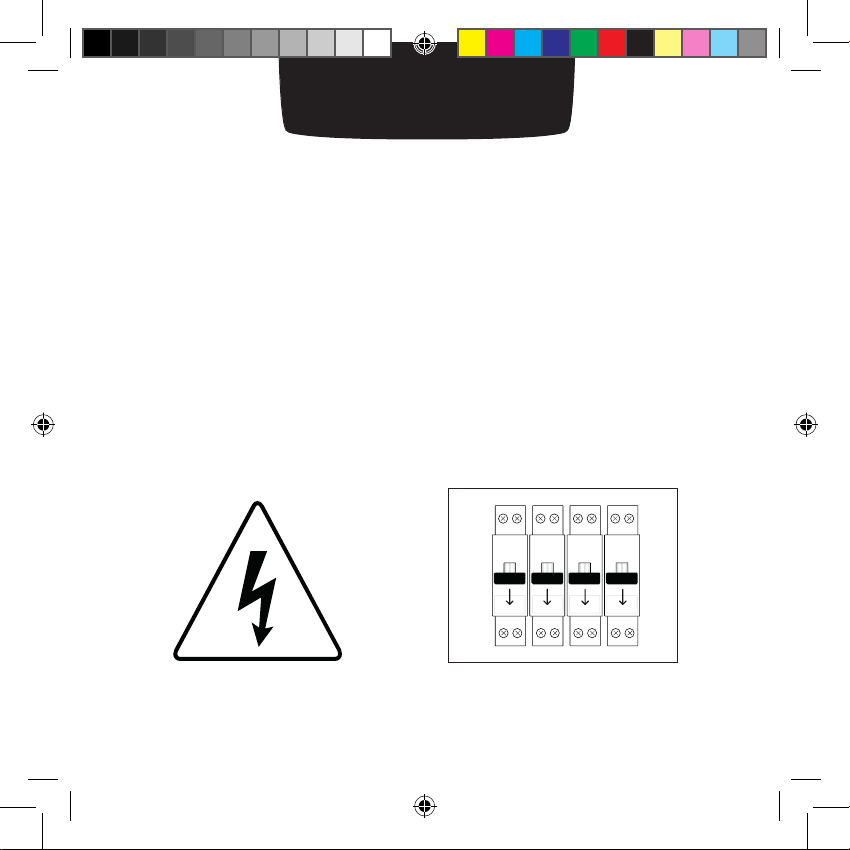
Warning!
• Read these instructions carefully before starting the installation.
• The Netatmo Thermostat must be installed according to
applicable standards.
• Before any intervention, make sure power is turned off.
Manuel 2_EN.indd 2 13/01/2014 10:26:46
Page 3
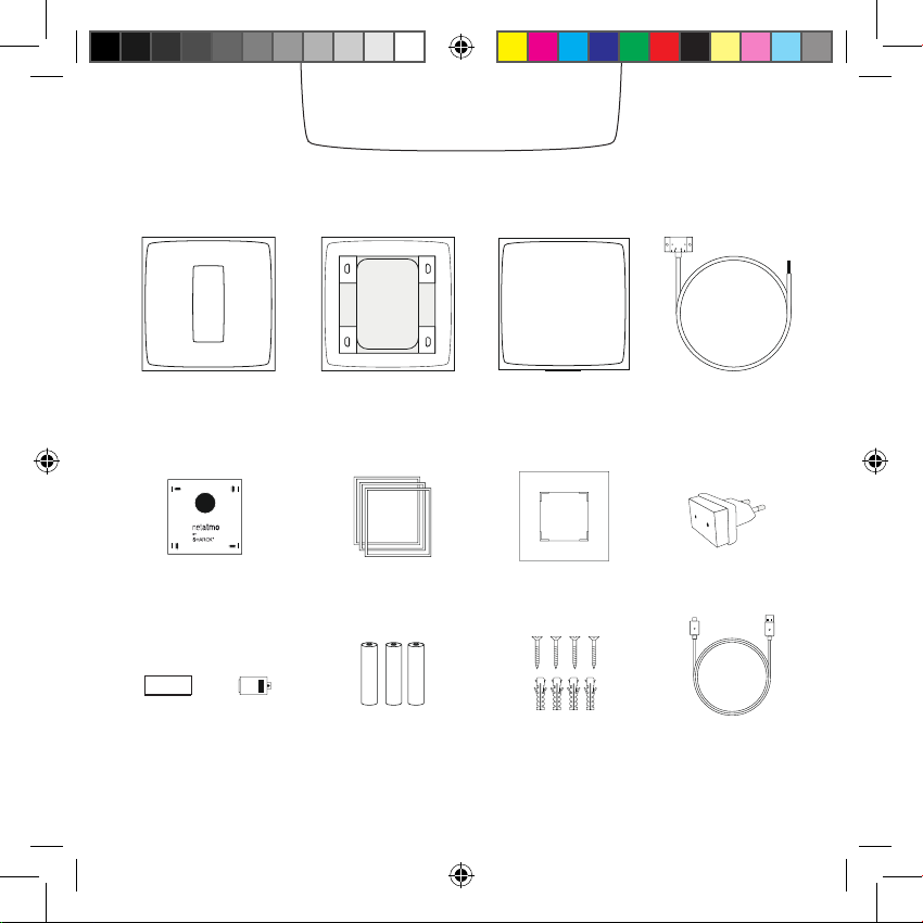
In the box
Thermostat Relay Boiler adapter
Mounting Plate
Tape Cover
Manuel 2_EN.indd 3 13/01/2014 10:26:47
Mobile stand
Color Adhesives (Trim plate)*
3 AAA batteries
* not used in this setup
4 screws
4 screw anchors
(Mains adapter)*
1 USB cable
Page 4
Open the boiler door using the
manual, if necessary.
Find your former thermostat’s
relay. Follow its wires to identify
to which boiler terminals they are
connected.
Take a picture of the wiring.
Note: Some thermostats are
connected to different terminals from
those on the diagram’s list (for example, eBus, EMS…). In this case,
you will have to identify the right
thermostat terminals, labeled LS-LR,
TA, or COM-NO
Identify
P / N
L / N
220V Power supply terminals
Usually blue and brown wires
LS / LR
or
or
TA
or
COM / NO
Thermostat terminal
Usually black or grey
wires
Manuel 2_EN.indd 4 13/01/2014 10:26:47
Page 5
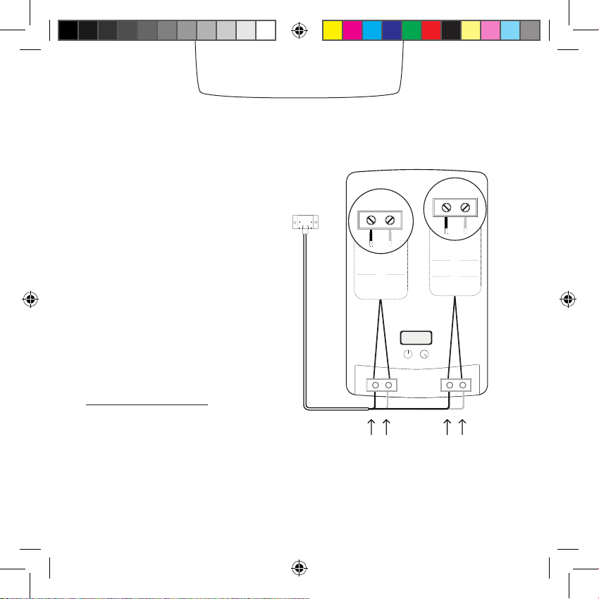
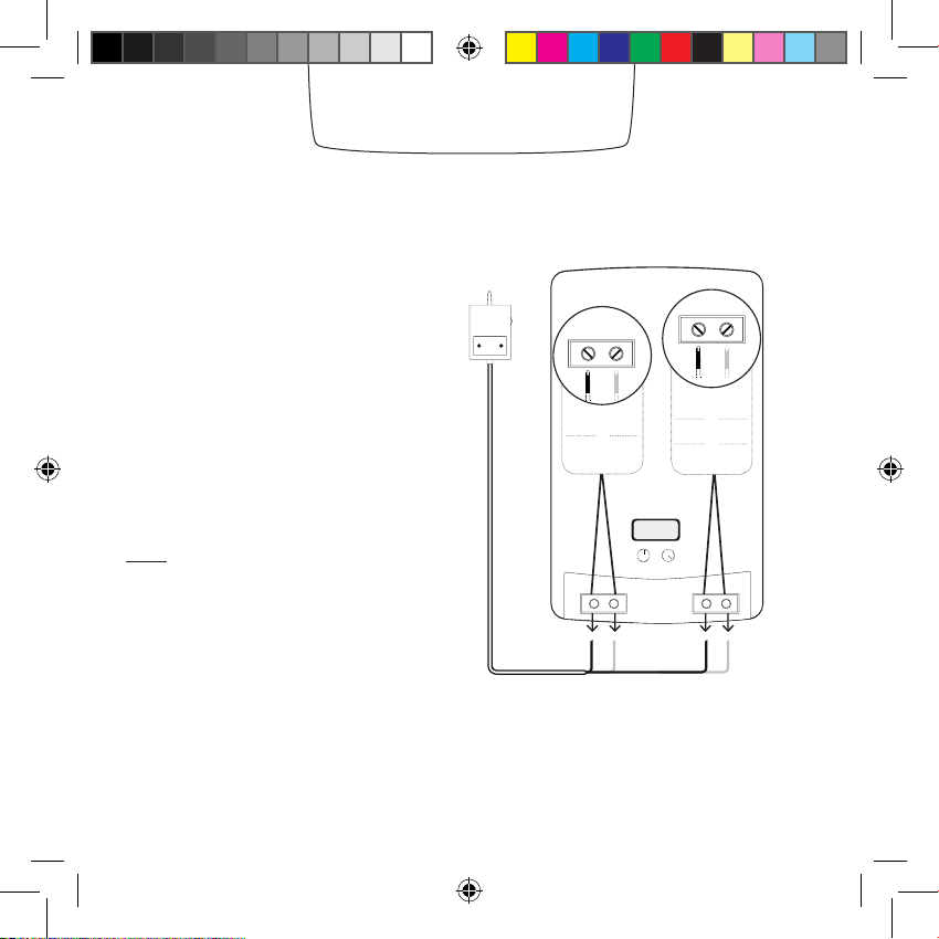
Disconnect your former thermostat’s relay.
Connect the wires of the boiler
adapter in place of the former
thermostat’s relay, as shown on
the diagram.
Our forum can help you identify
where to plug the wires in,
at forum.netatmo.com.
In doubt, please send a picture
of your wiring to:
photo@netatmo.com
and our support team will help
you identify the right terminals.
Replace
P / N
L / N
220V Power supply terminals
Blue and brown wires
Ls / LR
or
or
TA
or
COM / NO
Thermostat terminal
Black and grey wires
Manuel 2_EN.indd 5 13/01/2014 10:26:47
Page 6
Note: If the relay does not blink after turning the power back on, it is not power supplied.
Please check how the blue and brown wires are wired. Do not forget to switch off the power
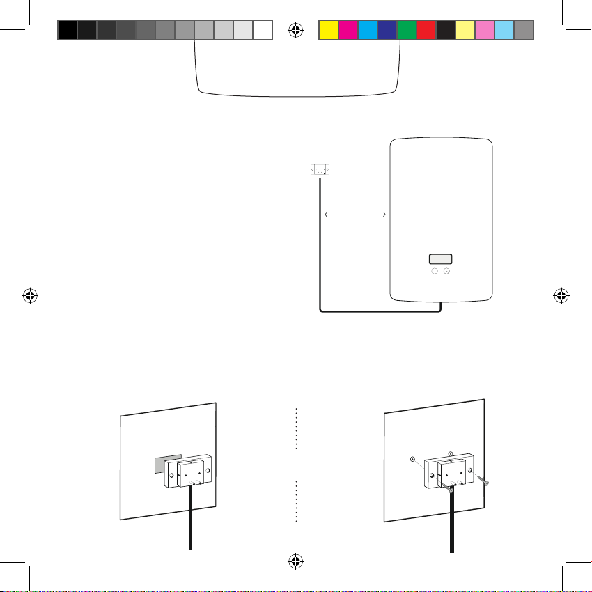
Setting the relay
The boiler adapter should be placed
as far as possible from metallic items
(wiring, pipes, electrical grid…).
The boiler adapter can be afxed to the wall with the double-sided tape
or the screws provided.
or
30 cm
Manuel 2_EN.indd 6 13/01/2014 10:26:48
Page 7

Testing the relay
Connect the relay into the boiler
1
adapter.
Switch the power supply back on.
2
3
The relay will blink blue.
Note: If the relay does not blink after turning the power back on, it is not power supplied.
Please check how the blue and brown wires are wired. Do not forget to switch off the power
Manuel 2_EN.indd 7 13/01/2014 10:26:48
supply before any intervention.
Page 8

Testing the relay
1
Push the relay
button.
The relay will light up blue
and switch on the boiler.
3
Push the relay
button again.
Note: If the boiler doesn’t switch on when the blue light is on, the relay is incorrectly wired to the
boiler. In this case, check where the grey and black wires are connected. In doubt, please read in
your boiler’s instructions manual [ the «room thermostat» section].
The relay light will turn off
to indicate the boiler is off.
2
4
Manuel 2_EN.indd 8 13/01/2014 10:26:48
Page 9

Thermostat
1 2
Insert the batteries into
the Thermostat.
+
5
21
20
If the Thermostat has found the
relay, it will display the setpoint and
the room temperatures.
Manuel 2_EN.indd 9 13/01/2014 10:26:48
Desired temperature
0
Measured temperature
The Thermostat will display the
start screen and search for
the relay.
+
5
21
or
If the Thermostat hasn’t found the
relay, it will display the «!» symbol.
In this case, move the relay closer to
the Thermostat and wait until the «!»
0
20
symbol disappears.
Page 10

Test
1
Tap the top of the Thermostat until
the screen shows «MAX».
The Thermostat will switch on the
boiler.
2
Tap the bottom of the Thermostat
until it displays «OFF».
The Thermostat will switch off the
boiler.
clic
+
21
20
+
20
5
0
0
20
+
+
0
0
20
clic
Manuel 2_EN.indd 10 13/01/2014 10:26:49
Page 11

Customisation
You can choose to customise your Thermostat
1
by using one of the colour adhesives.
2
Take off the outer frame of the adhesive.
3
Stick it on the back of your Thermostat.
Manuel 2_EN.indd 11 13/01/2014 10:26:49
Page 12

Location
22
18
5
+
or
Clip the Thermostat on its mobile
stand and place it on a shelf in the
Set the Thermostat on the mounting
plate.
living room.
1 m 1 m
1.5 m
More than 1m from the
1.5m high
openings
Manuel 2_EN.indd 12 13/01/2014 10:26:50
Away from any cold or
heat source
Page 13

App
To use your Thermostat from your smartphone, tablet or
computer, visit:
http://thermostat.netatmo.com
PC / Mac Smartphone / Tablettes
Manuel 2_EN.indd 13 13/01/2014 10:26:50
Page 14

Specications
SIZE
Thermostat : 83x83x22 mm
DESIGN
Designed by Starck.
Translucent minimalist plexiglass cube.
5 interchangeable colors in the box.
SENSORS AND MEASUREMENTS
Temperature (measurement):
Ranges from 0°C to 50°C
Accuracy: +- 0.5° C
Temperature (setpoint):
Ranges from 7°C to 30°C
Increment: 0.5°C
Unit: °C
E-INK DISPLAY
Energy efcient, longer battery life and
optimal readability.
FREE APP, LIFETIME SUPPORT
No subscription fee.
App available on the App Store and on
Google Play.
Free access to your online personal
dashboard.
Accessible from multiple devices.
WIRELESS SPECIFICATIONS
Wi-Fi 802.11 b/g/n compatible (2.4GHz).
Supported security: Open/WEP/WPA/
WPA2-personal (TKIP and AES).
Wireless connection between thermostat and relay:
radio long range 100m.
POWER AND BATTERIES
3 AAA batteries.
1 year battery life.
SETUP AND COMPATIBILITY
Compatible with gas, fuel and wood boilers.
Switching current: max 4 A
Switching voltage: max 250 VAC
Switching power: max 120 W
COMPATIBLE WITH IPHONE AND IPAD
iPhone 4, iPhone 4s, iPhone 5, iPhone 5c / 5s
iPad mini, iPad mini with Retina display, iPad 2,
iPad (3rd generation), iPad (4th generation),
iPad Air
iPod touch (5th generation)
COMPATIBLE WITH ANDROID SMARTPHONE
Android 4.0 required
Manuel 2_EN.indd 14 13/01/2014 10:26:50
Page 15

Manuel 2_EN.indd 15 13/01/2014 10:26:50
Page 16

Page 17

FCC WARNING
This device complies with Part 15 of the FCC Rules. Operation is subject to the following two
conditions:
(1) This device may not cause harmful interference, and
(2) this device must accept any interference received, including interference that may cause
undesired operation.
NOTE 1: Any changes or modifications to this unit not expressly approved by the party
responsible for compliance could void the user's authority to operate the equipment.
 Loading...