

Page 1
Prepare
for installation
Install
hardware
Cable
the node
Configure
the node
1 2 3
NetApp HCI compute and storage nodes
Installation and Setup Instructions
4
Perform
post-deployment
tasks
5
Prepare for installation | Stage 1
UID
NODE B
NODE B
NODE A
NODE A
UID
A0 A1 A2 A3 A4 A5 B0 B1 B2 B3 B4 B5 C0 C1 C2 C3 C4 C5 D0 D1 D2 D3 D4 D5
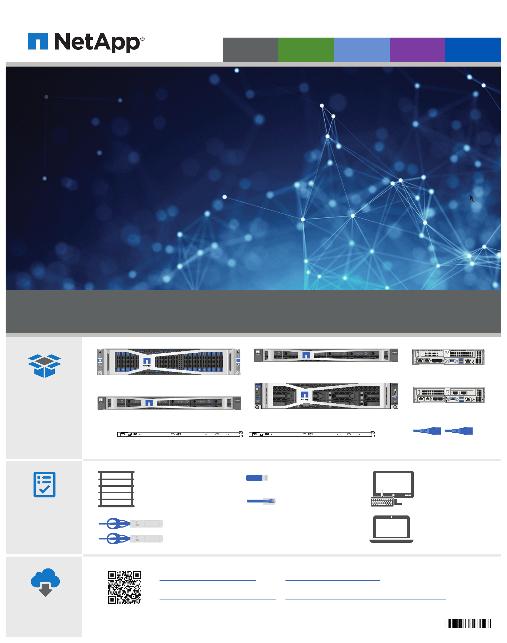
In the box
You provide
NetApp HCI chassis (only for H410S and H410C)
H615C compute node (order dependent)
Slide rail kit
Rack space (order dependent)
H410C and H410S: 2U per chassis
H610C: 2U per chassis
H610S: 1U per chassis
H615C: 1U per chassis
SFP28/SFP+
direct-attach cables
or transceivers
UID
NODE D
NODE D
HCI
NODE C
NODE C
UID
H610S storage node (order dependent)
H610C compute node (order dependent)
USB stick (optional)
CAT5e or higher cable
with RJ45 connector
H410C and H410S: Optional,
for out-of-band management
H610C: Optional, recommended
H615C and H610S: Required for out-of-band
management and cluster management
H410S storage node
(order dependent)
H410C compute node
(order dependent)
Power cables
(Two per chassis)
Monitor with a
VGA connection
and keyboard with
a standard USB
connection
Any operating
system (OS) client
with a browser
Access online
• End User License Agreement
• Hardware Universe (HWU)
• NetApp HCI Documentation Center
• NetApp HCI Resources page
• NetApp SolidFire Resources page
• SolidFire and Element 11.3 Documentation Center
215-14243_B0
Page 2

Install hardware | Stage 2
SSD
-
E
S
-
E
S
-E
S
-E
S
-E
S
-E
S
-E
S
-E
S
-
E
S
-E
S
-E
S
-E
S
-E
S
-
E
S
-
E
S
-E
S
-E
S
-E
S
-E
S
-E
S
-E
S
-E
S
-E
S
-E
1
B
1
B
1
B
1
B
1
B
1
B
1
B
1
B
1
B
1
B
1
B
1
B
1
B
1
B
1
B
1
B
1
B
1
B
1
B
1
B
1
B
1
B
1
B
1.9T B
Steps 1 and 2 apply only if you are setting up a new system.
1
Install the rails.
Note:
• Ensure that you have installed the rack according to the safety instructions from the manufacturer.
• Ensure that the rack is stabilized. The heaviest equipment should be at the bottom of the rack.
• Follow proper grounding practices to avoid risk of electric shock.
• Follow proper airflow and cooling requirements to prevent hardware from overheating.
• Installing the chassis requires two people.
2
Install the chassis.
See Rail Kit Installation instructions.
H410C, H615C,
and H410S
CAUTION
Approximately
70 lb (31.75 kg)
LIFTING HAZARD
H610C
CAUTION
77.1 lb (35 kg)
LIFTING HAZARD
H610S
CAUTION
40.5 lb (18.4 kg)
LIFTING HAZARD
The minimum initial NetApp HCI configuration requires two chassis.
The installation graphic
is only for illustrative
purposes. Your actual
node might dier based
on what you ordered.
Steps 3 and 4 apply only if you are installing H410C and H410S nodes in a NetApp H-series chassis.
3
Install nodes in the chassis.
CHASSIS BACK VIEW
PORT 1 PORT 2
LNK
ACT
Node D
PORT 1 PORT 2
LNK
Node C
4
Install drives for storage nodes.
ACT
CHASSIS FRONT VIEW
.9T
.9T
.9T
SD
SD
SD
T
.9T
.9T
.9T
.9
.9T
SD
SD
.9T
SD
SD
SD
SD
Node B Node C Node DNode A
T
.9T
.9T
.9T
.9
SD
SD
SD
9T
.9T
.
.9T
SD
.9T
SD
SD
SD
PORT 1 PORT 2
LNK
ACT
Node B
PORT 1 PORT 2
LNK
ACT
.9T
.9T
.9T
.9T
.9T
SD
SD
SD
.9T
SD
SD
SD
SD
Node A
Page 3
Cable the node | Stage 3
1
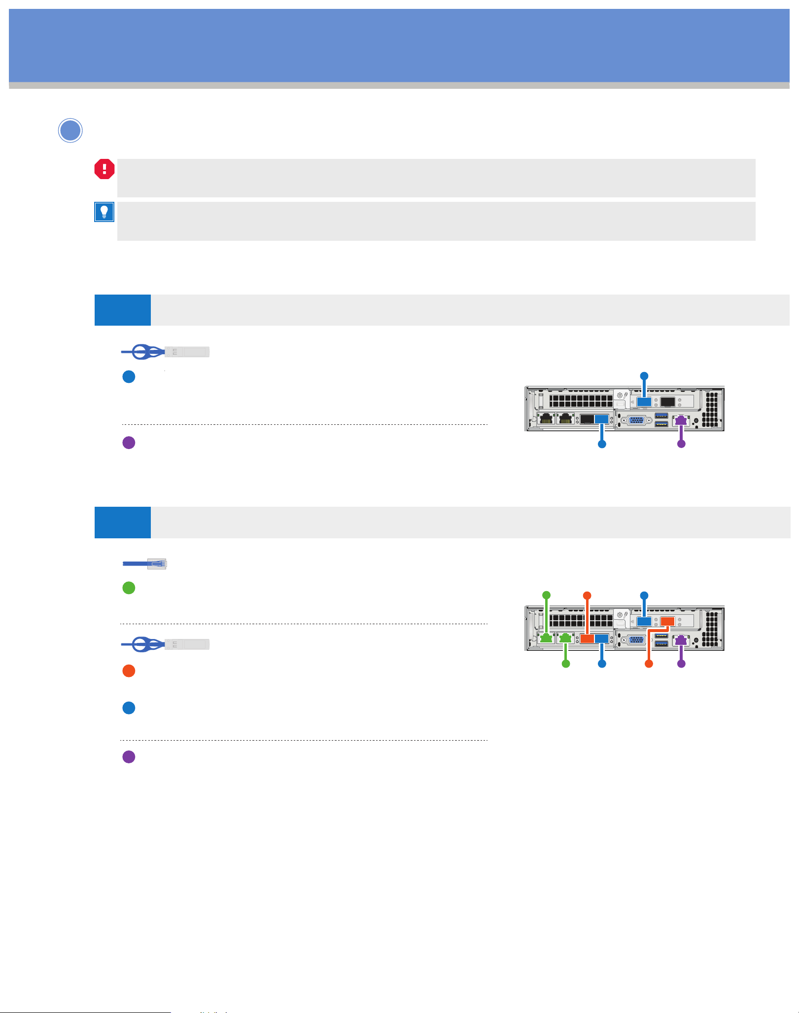
Cable the compute node.
If the airflow vents at the rear of the chassis are blocked by cables or labels, it can lead to premature
component failures due to overheating.
If you are adding nodes to an existing NetApp HCI installation, ensure that the cabling and network
configuration of the nodes that you add are identical to the existing installation.
H410C compute nodes (choose option A or B)
OPTION
A
OPTION
B
Two-cable configuration
10/25GbE cables
Connect two SFP28/SFP+ cables or transceivers
for shared management, virtual machines, and
storage connectivity.
(Optional, recommended)
Connect a CAT5e cable in the IPMI port for
out-of-band management connectivity.
Six-cable configuration
1/10GbE cables
Connect two CAT5e or higher cables in ports
A and B for management connectivity.
Port CPort A
Port D
Port E
IPMI
Port E
10/25GbE cables
Connect two SFP28/SFP+ cables or transceivers
in ports C and F for virtual machine connectivity.
Connect two SFP28/SFP+ cables or transceivers
in ports D and E for storage connectivity.
(Optional, recommended)
Connect a CAT5e cable in the IPMI port for
out-of-band management connectivity.
Port B
Port D
Port F IPMI
Page 4
Cable the node | Stage 3 cont.
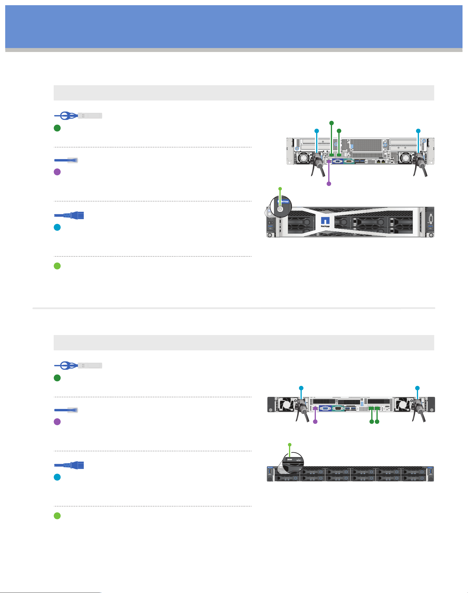
H610C compute node
Note: H610C nodes are deployed only in the two-cable configuration. Ensure that all the VLANs are present on ports C and D.
10/25GbE cables
Connect the node to a 10/25GbE network using
two SFP28/SFP+ cables in ports C and D.
1/10GbE cables
(Optional, recommended)
Connect the node to a 1GbE network using an
RJ45 connector in the IPMI port.
REAR
VIEW
PortC
PortD
IPMI
FRONT
VIEW
Power cables
Connect both power cables to the node.
Plug the power cables to a 200‐240V
power outlet.
Press the power button at the front of the chassis.
Note: It takes approximately five minutes and 30 seconds
for the node to boot.
H615C compute node
Note: H615C nodes are deployed only in the two-cable configuration. Ensure that all the VLANs are present on ports A and B.
10/25GbE cables
Connect the node to a 10/25GbE network using
two SFP28/SFP+ cables in ports A and B.
REAR
VIEW
1/10GbE cables
(Optional, recommended)
Connect the node to a 1GbE network using an
RJ45 connector in the IPMI port.
Power cables
Connect both power cables to the node.
Plug the power cables to a 110-140V
power outlet.
Press the power button at the front of the chassis.
IPMI
Port A Po
rt B
FRONT
VIEW
Page 5
Cable the node | Stage 3 cont.
2
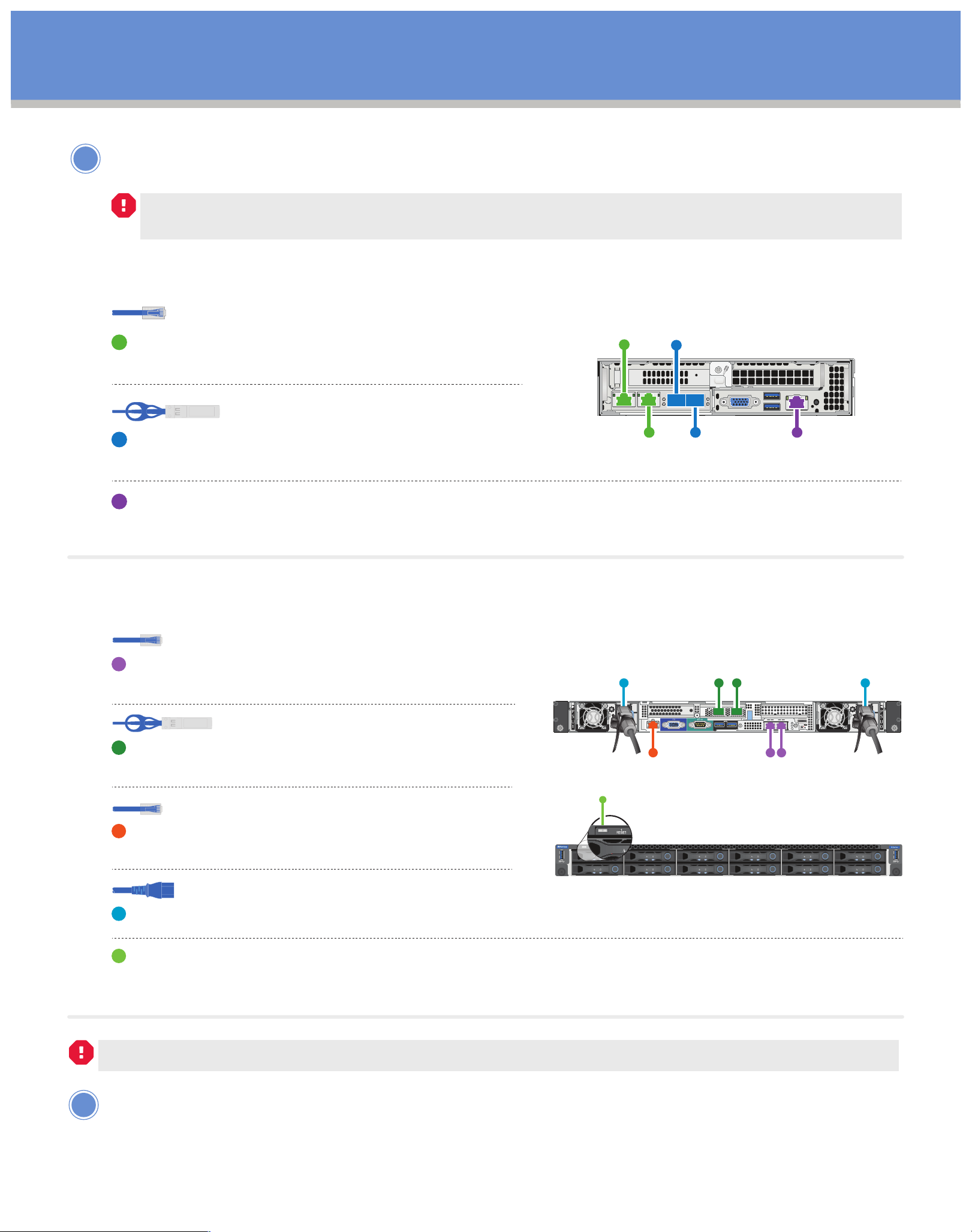
Cable the storage node.
If the airflow vents at the rear of the chassis are blocked by cables or labels, it can lead to premature
component failures due to overheating.
H410S storage node
1/10GbE cables
Connect two CAT5e or higher cables in ports
A and B for management connectivity.
10/25GbE cables
Port CPort A
Connect two SFP28/SFP+ cables or transceivers
Port B
Port D IPMI
in ports C and D for storage connectivity.
(Optional, recommended)
Connect a CAT5e cable in the IPMI port for out-of-band management connectivity.
H610S storage node
1GbE cables
Connect the node to a 1GbE network using
two RJ45 connectors.
10/25GbE cables
Connect the node to a 10/25GbE network using
two SFP28 or SFP+ cables.
1GbE cable
Connect the node to a 1GbE network using
an RJ45 connector in the IPMI port.
REAR
VIEW
1GbE RJ45 cable
for out-of-band
management
10/25GbE SFP+
or SFP28 cables
for iSCSI
1GbE RJ45 cables
for management
FRONT
VIEW
Power cables
Connect both power cables to the node.
Plug the power cables to a suitable power outlet. Press the power button at the front of the chassis.
Note: It takes approximately five minutes and 30 seconds for the node to boot.
Steps 3 and 4 apply only if you are installing H410C and H410S nodes in a chassis.
3
Connect the power cords to the two power supply units
per chassis and plug them into 240V PDU or power outlet.
This step does not apply if you are adding a new node to an existing chassis.
Page 6
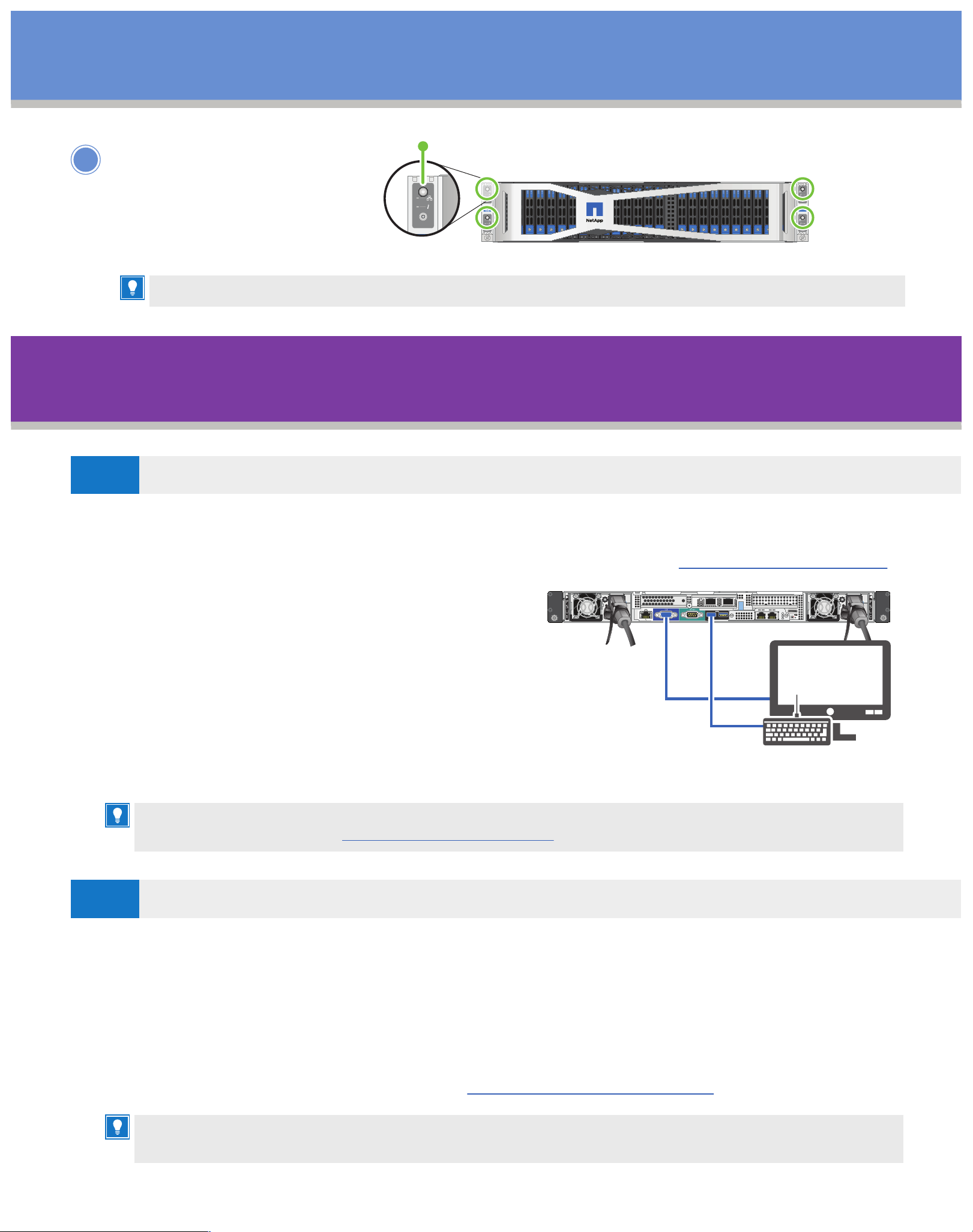
Cable the node | Stage 3 cont.
UID
NODE B
NODE B
4
Power on the
FRONT VIEW
NetApp HCI nodes.
It takes approximately six minutes for the node to boot.
Configure NetApp HCI | Stage 4
OPTION
A
1. Configure an IPv4 address on the management network (Bond1G) on one storage node.
Setting up a new NetApp HCI installation
UID
NODE B
NODE B
NODE A
NODE A
UID
A0 A1 A2 A3 A4 A5 B0 B1 B2 B3 B4 B5 C0 C1 C2 C3 C4 C5 D0 D1 D2 D3 D4 D5
(Choose option A or B below)
UID
NODE D
NODE D
HCI
NODE C
NODE C
UID
Note: If you are using DHCP on the management network, you can connect to the DHCP-acquired IPv4 address of the
storage system. For more information about DHCP-acquired IPv4 addresses, see the
NetApp HCI Deployment Guide
a. Plug in a KVM to the back of one storage node.
b. Configure the IP address, subnet mask, and
gateway address for Bond1G in the user interface.
You can also configure a VLAN ID for the
Bond1G network.
2. Using a supported web browser (Mozilla Firefox,
Google Chrome, or Microsoft Edge), navigate to the
NetApp Deployment Engine by connecting to the IPv4
address that you configured in Step 1.
3. Use the NetApp Deployment Engine user interface (UI) to configure NetApp HCI.
All the other NetApp HCI nodes that you installed will be discovered automatically.
OPTION
B
For more information, see the
.
Expanding an existing NetApp HCI installation
NetApp HCI Deployment Guide.
.
Note: If you are expanding your installation using H615C compute nodes, you must ensure that the cluster runs
on NetApp HCI 1.7 or later.
1. Using a supported web browser, browse to the IP address of the management node.
2. Log in to the NetApp Hybrid Cloud Control by providing the NetApp HCI storage cluster
administrator credentials.
3. Follow the steps in the wizard to add storage and/or compute nodes to your NetApp HCI
installation. The newly installed NetApp HCI nodes on the same network will be discovered
automatically. For more information, see the NetApp HCI Deployment Guide.
The cabling and network configuration of the nodes that you add must be identical to the existing
NetApp HCI installation.
Page 7

Perform post-deployment tasks | Stage 5
UID
NODE D
NODE D
H610C compute node
Install the GPU drivers in ESXi for each H610C node that you installed, and validate their functionality.
See the NetApp Deployment Guide.
H615C compute node
• If your H615C node has GPUs in it, install the GPU driver.
See the NetApp Deployment Guide.
• Configure out-of-band management using the Baseboard Management Controller (BMC).
1. Use a web browser and navigate to the default BMC IP address: 192.168.0.120
2. Log in using the following default credentials: User name: root Password: calvin
3. From the node management screen, navigate to Settings > Network Settings, and configure
the network parameters for the out-of-band management port.
H610S storage node
Configure out-of-band management using the Baseboard Management Controller (BMC).
1. Use a web browser and navigate to the default BMC IP address: 192.168.0.120
2. Log in using the following default credentials: User name: root Password: calvin
3. From the node management screen, navigate to Settings > Network Settings, and configure
the network parameters for the out-of-band management port.
See How to access BMC and change IP address on H610S.
 Loading...