

Page 1

NetApp® EF550 Flash Array
Installation Guide
NetApp, Inc.
495 East Java Drive
Sunnyvale, CA 94089
U.S.
Telephone: +1 (408) 822-6000
Fax: +1 (408) 822-4501
Support telephone: +1 (888) 463-8277
Web: http://www.netapp.com
Feedback: [email protected]
Part number: 215-08288_A0
Release date: December 2013
Page 2

Page 3

Table of Contents
About This Guide.......................................................................................................................................................... 1
Registering your EF550 Flash Array...........................................................................................................................2
Step 1 – Preparing for an EF550 Flash Array Installation........................................................................................ 3
Key Terms.................................................................................................................................................................3
storage array.......................................................................................................................................................3
controller..............................................................................................................................................................4
Gathering Items.........................................................................................................................................................4
Basic Hardware...................................................................................................................................................5
EF550 Configuration Cables and Connectors....................................................................................................5
Tools and Other Items........................................................................................................................................7
Things to Know – Cables, SFPs, and QSFPs......................................................................................................... 8
Things to Know – Taking a Quick Glance at the Hardware in a EF550 Flash Array Configuration..........................9
Step 2 – Installing and Configuring the Switches................................................................................................... 14
Things to Know – Switches and Routers............................................................................................................... 14
Procedure – Installing and Configuring Switches...................................................................................................15
Step 3 – Installing the Host Bus Adapters for the EF550 Flash Array.................................................................. 17
Key Terms...............................................................................................................................................................17
host channel adapter........................................................................................................................................17
HBA host port...................................................................................................................................................17
HCA host port...................................................................................................................................................18
HCA host port Global Unique Identifier (GUID)...............................................................................................18
Things to Know – Host Bus Adapters, Host Channel Adapters, and Ethernet Network Interface Cards................18
Procedure – Installing Host Bus Adapters..............................................................................................................18
Procedure – Installing Host Channel Adapters...................................................................................................... 19
Step 4 – Installing the EF550 Flash Array................................................................................................................20
Things to Know – General Installation................................................................................................................... 20
Procedure – Installing the the EF550 Flash Array................................................................................................. 20
Procedure – Installing Drives in the EF550 Flash Array........................................................................................25
Step 5 – Connecting the EF550 Flash Array to the Hosts......................................................................................27
Key Terms...............................................................................................................................................................27
switch or fabric topology...................................................................................................................................27
Things to Know – Storage Array Configuration Specifications for the EF550 Flash Array.....................................27
Things to Know – Host Channels...........................................................................................................................28
Procedure – Connecting Host Cables on a EF550 Flash Array.............................................................................29
Step 6 – Installing the Drive Trays for the EF550 Flash Array Configurations.....................................................34
Things to Know – General Installation of Drive Trays with the EF550 Flash Array................................................34
Procedure – Installing the Drive Trays...................................................................................................................34
Procedure – Installing Drives in the Drive Trays....................................................................................................39
Table of Contents - i
Page 4

Things to Know – Connecting the Power Cords....................................................................................................40
Procedure – Connecting the Power Cords.............................................................................................................41
Step 7 – Connecting the EF550 Flash Array to the Drive Trays............................................................................ 42
Key Terms...............................................................................................................................................................42
Things to Know – EF550 Flash Array....................................................................................................................42
Things to Know – Drive Trays................................................................................................................................43
Things to Know – Drive Tray Cabling Configurations for the EF550 Flash Array..................................................44
Procedure – Connecting the Drive Trays to the EF550 Flash Array......................................................................45
Step 8 – Connecting the Ethernet Cables................................................................................................................ 48
Key Terms...............................................................................................................................................................48
Things to Know – Connecting Ethernet Cables..................................................................................................... 48
Procedure – Connecting Ethernet Cables..............................................................................................................49
Step 9 – Connecting the Power Cords..................................................................................................................... 50
Things to Know – AC Power Cords.......................................................................................................................50
Procedure – Connecting AC Power Cords.............................................................................................................50
Step 10 – Turning on the Power and Checking for Problems in an EF550 Flash Array Configuration...............51
Procedure –Turning On the Power to the Storage Array and Checking for Problems in a EF550 Flash Array
Configuration........................................................................................................................................................... 51
Things to Know – LEDs on the EF550 Flash Array or the EF550 Flash Array......................................................52
Things to Know – General Behavior of the LEDs on the Flash Array....................................................................58
Things to Know – Service Action Allowed LEDs....................................................................................................60
Things to Know – LEDs on the Drive Tray............................................................................................................61
General Behavior of the LEDs on the Drive Trays.................................................................................................65
Things to Know – Seven Segment Display Sequence Code Definitions on the EF550 Flash Array......................66
Things to Know – Seven-Segment Component Failure Identifications for the EF550 Flash Array.........................67
Things to Know – Lock-Down Codes for the Flash Array......................................................................................68
Things to Know – Seven-Segment Display Use Cases.........................................................................................70
Things to Know – Seven-Segment Display for the ESMs on the Drive Trays....................................................... 71
Regulatory Compliance Statements.......................................................................................................................... 73
Copyright information.................................................................................................................................................75
Trademark information................................................................................................................................................76
How to send your comments.....................................................................................................................................77
ii - Table of Contents
Page 5

About This Guide
Use this document to install the EF550 flash array and all attached drive trays for your configuration. To access these
products, go to the NetApp Support Site at support.netapp.com
215-08288_A0_EF550 Flash Array Installation Guide - 1
Page 6

Registering your EF550 Flash Array
Before you begin the installation, register your EF550 Flash Array at support.netapp.com using the serial number for
the integrated flash array. Use of any other component serial numbers (such as those for individual controllers or drive
trays) will not enable correct registration for the flash array. The integrated flash array serial number is located on two
places on each flash array: the large UL label attached to the top of an enclosure, and a silver label attached to the
front of the enclosure, either on the bottom lip or the right ear. In both of these places, the integrated flash array serial
number is identified by the text "Serial" or "S/N."
Record the integrated flash array serial number for later use. This serial number is required to initiated any support
request for your system.
If your storage array includes drive trays as well, you must verify that you install the controllers in the integrated flash
array, and not in any of the expansion drive tray enclosures. Integrated flash arrays and expansion drive trays look
similar, so you must refer to the integrated flash array part numbers in your Sales Order to identify the integrated flash
array. (Integrated flash arrays do not include a "QS" designator in their part numbers. Drive tray part numbers do
include a "QS" designator. To enable proper support registration, do not install controllers in drive trays.)
2 - 215-08288_A0_EF550 Flash Array Installation Guide
Page 7
Step 1 – Preparing for an EF550 Flash Array Installation
Storage arrays for 6-Gb/s SAS drives consist of a EF550 flash array model and can have one or more drive trays in a
cabinet:
Use this document to install the following EF550 flash array and all necessary drive trays for your configuration:
The following table shows the various configuration options.
Table 1. EF550 Flash Array Options
EF550 Configurations Options
Duplex EF550 flash array
with a host interface card
ATTENTION Possible hardware damage – To prevent electrostatic discharge damage to the tray, use proper
antistatic protection when handling tray components.
Any combination of EF550 flash arrays attached to drive trays, not to exceed a
maximum of 120 drive slots.
One of the following host interface cards (per controller):
Two 40-Gb/s IB ports
Four 6-Gb/s mini-SAS SFF-8088 ports
Four 16-Gb/s Fibre Channel ports
Four 10-Gb/s iSCSI ports
Three 4-GB DIMM memory for 12-GB capacity per controller.
Key Terms
Gathering Items
Things to Know – Cables, SFPs, and QSFPs
Things to Know – Taking a Quick Glance at the Hardware in a EF550 Flash Array Configuration
Key Terms
storage array
flash array
controller
drive tray
environmental services module (ESM)
storage array
A collection of both physical components and logical components for storing data. Physical components include solid
state drives (SSDs), controllers, ESMs, fans, and power supplies. Logical components include disk pools, volume
groups, and volumes. These components are managed by the storage management software.
215-08288_A0_EF550 Flash Array Installation Guide - 3
Page 8

flash array
One tray with drives, one or two controllers, fans, and power supplies. The flash array provides the interface between
a host and a storage array.
controller
A circuit board and firmware that is located within a flash array. A controller manages the input/output (I/O) between
the host system and data volumes.
drive tray
One tray with drives, one or two environmental services modules (ESMs), power supplies, and fans. A drive tray does
not contain controllers.
environmental services module (ESM)
A canister in the drive tray that monitors the status of the components. An ESM also serves as the connection point to
transfer data between the drive tray and the controller.
Gathering Items
Before you start installing the flash array, you must have installed the cabinet in which the flash array will be mounted.
Use the tables in this section to verify that you have all of the necessary items to install the flash array.
ATTENTION Possible hardware damage – To prevent electrostatic discharge damage to the tray, use proper
antistatic protection when handling tray components.
Basic Hardware
EF550 Configuration Cables and Connectors
Tools and Other Items
4 - 215-08288_A0_EF550 Flash Array Installation Guide
Page 9
Basic Hardware
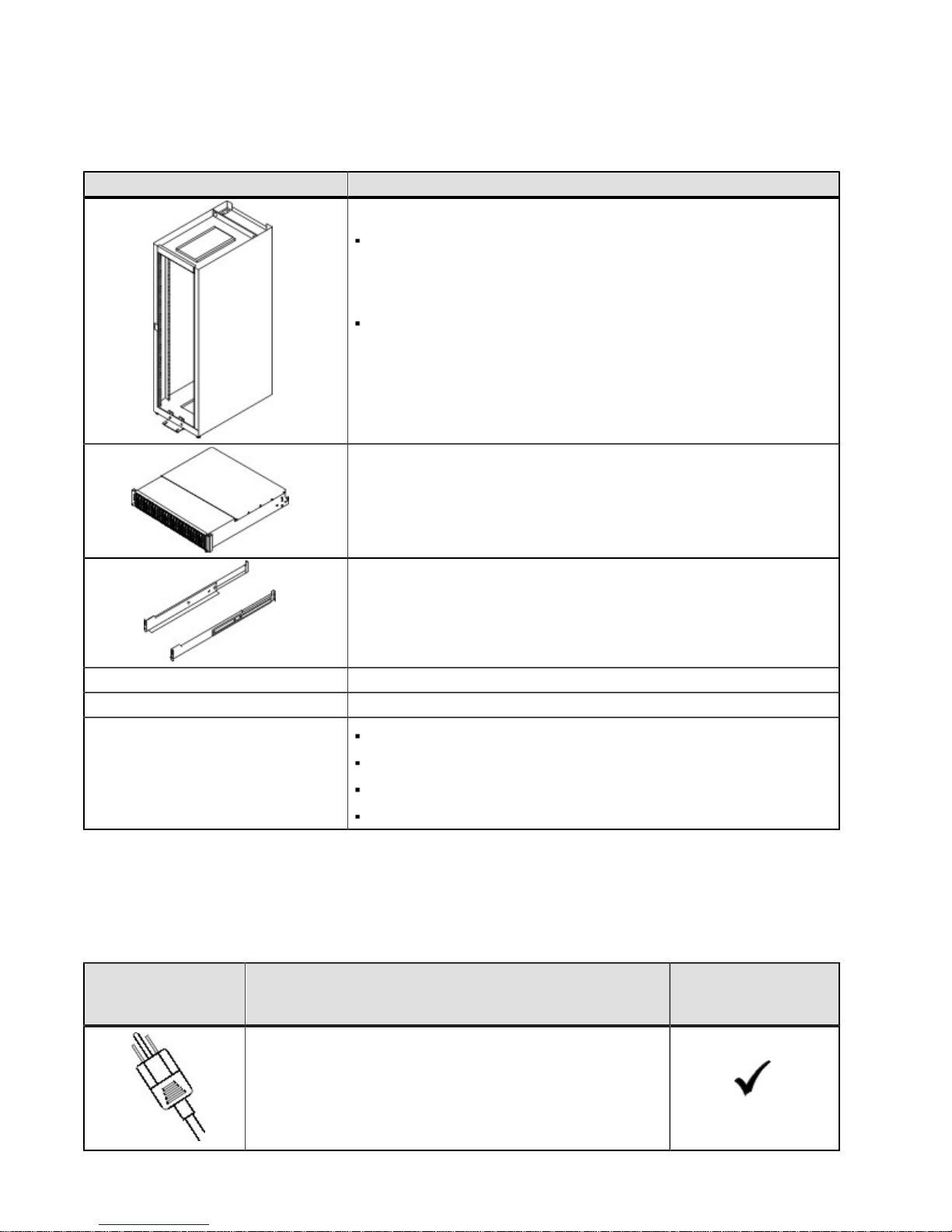
Table 2. Basic Hardware
Item
Cabinet
Make sure that your cabinet meets the installation site
specifications of the various EF550 storage array components.
Refer to the Storage System Site Preparation Guide for more
information.
Depending on the power supply limitations of your cabinet, you
might need to install more than one cabinet to accommodate the
different components of the EF550 storage array. Refer to the
installation guide for your cabinet for instructions on installing the
cabinet.
Drive Trays with end caps that are packaged separately. This drive
tray can be used with all three variations of the EF550 flash array.
Mounting rails and screws
The mounting rails that are available with the drive tray are designed
for an industry-standard cabinet.
InfiniBand switch (optional)
Gigabit Ethernet switch for Management (optional)
Host with InfiniBand host channel adapters (HBAs) (optional)
Host with SAS HBAs (optional)
Host with Fibre Channel HBAs (optional)
Host with iSCSI HBAs (optional)
EF550 Configuration Cables and Connectors
Table 3. Cables and Connectors
Item Included with the
AC power cords.
The flash array and the drive trays ship with power cords for
connecting to an external power source, such as a wall plug.
Your cabinet might have special power cords that you use
instead of the power cords that ship with the flash array and
the drive trays.
Flash Array or Drive
Trays
215-08288_A0_EF550 Flash Array Installation Guide - 5
Page 10
Item Included with the
Flash Array or Drive
Trays
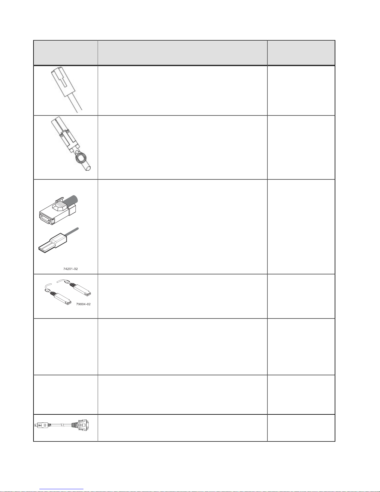
Ethernet cable
For information about out-of-band storage array
management, see the description for “Deciding on the
Management Method” in the Initial Configuration and
Software Installation Guide.
SAS host cables
1m-to-10m passive SAS cables
25m active cables
1m-to2m fan-out single x4 port to 4-single port passive
cables
Both controllers must be individually connected to the drive
tray.
SAS expansion cables
1-5 m passive cables for Mini SAS 8088 host ports.
InfiniBand cables
Use these cables for InfiniBand connections to hosts with
the host interface card.
7m Cu, 15m Active Cu, and 300m Optical cables used to
connect the InfiniBand HIC to the host.
Optical Fibre Channel with SFP transceivers
SFP transceivers are only included with the flash array when
a fibre channel HIC is ordered.
2, 3, 5, 10 or 25m OM2 cables
50 to 100m OM3 cables
300m OS1 or OS2 cables
iSCSI with SFP+ transceivers
Up to 7m twin-ax passive copper cables
2, 3, 5, 10 or 25m OM2 cables
25 to 300m OM3 cables
Serial cable
This cable is used for support only. You do not need to
connect it during initial installation.
6 - 215-08288_A0_EF550 Flash Array Installation Guide
Page 11
Item Included with the
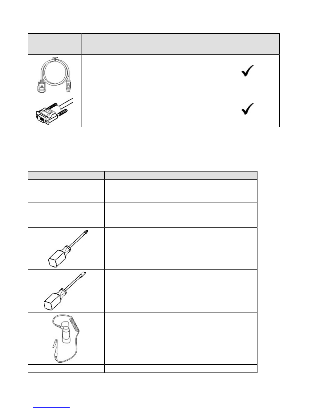
DB9-to-PS2 adapter cable
This cable adapts the DB9 connector on commercially
available serial cables to the PS2 connector on the ESM
for drive trays in the storage array. This cable is used
for support only. You do not need to connect it during
installation.
Serial Port cable
This 2-meter cable adapts the DB9 connector on
commercially available serial cables to the mini-USB port on
the controller.
Tools and Other Items
Table 4. Tools and Other Items
Flash Array or Drive
Trays
Item
Labels
Help you to identify cable connections and lets you more easily
trace cables from one tray to another
A cart
Holds the tray and components
A mechanical lift (optional)
A Phillips screwdriver
A flat-blade screwdriver
Anti-static protection
A flashlight
215-08288_A0_EF550 Flash Array Installation Guide - 7
Page 12

Things to Know – Cables, SFPs, and QSFPs
The figures in this topic display the SAS copper cables and SAS cables with a SFF-8088 Connector, QSFPs for IB
connections using copper cables, QSFP transceiver connectors for IB connections using optical cables, an SFP
transceiver with a Fibre-Optic cable, a passive SFP transceiver with a copper cable for 10Gb/s iSCSI connections,
and an iSCSI cable with an RJ-45 connector. The table references the SFP transceivers that apply if you are using
Fibre Channel host connections.
The flash array supports SAS drive connections and SAS, InfiniBand, Fibre Channel, or iSCSI host connections.
Figure 1. SAS Cable Connection
1. SAS Cable
2. SFF-8088 Connector
Figure 2. InfiniBand QSFP Connection With Copper Cables
Figure 3. InfiniBand QSFP Transceiver For Use With Optical Cables
Figure 4. SFP Transceiver and Fibre Optic Cable
1. SFP Transceiver
2. Fibre Optic Cable
8 - 215-08288_A0_EF550 Flash Array Installation Guide
Page 13
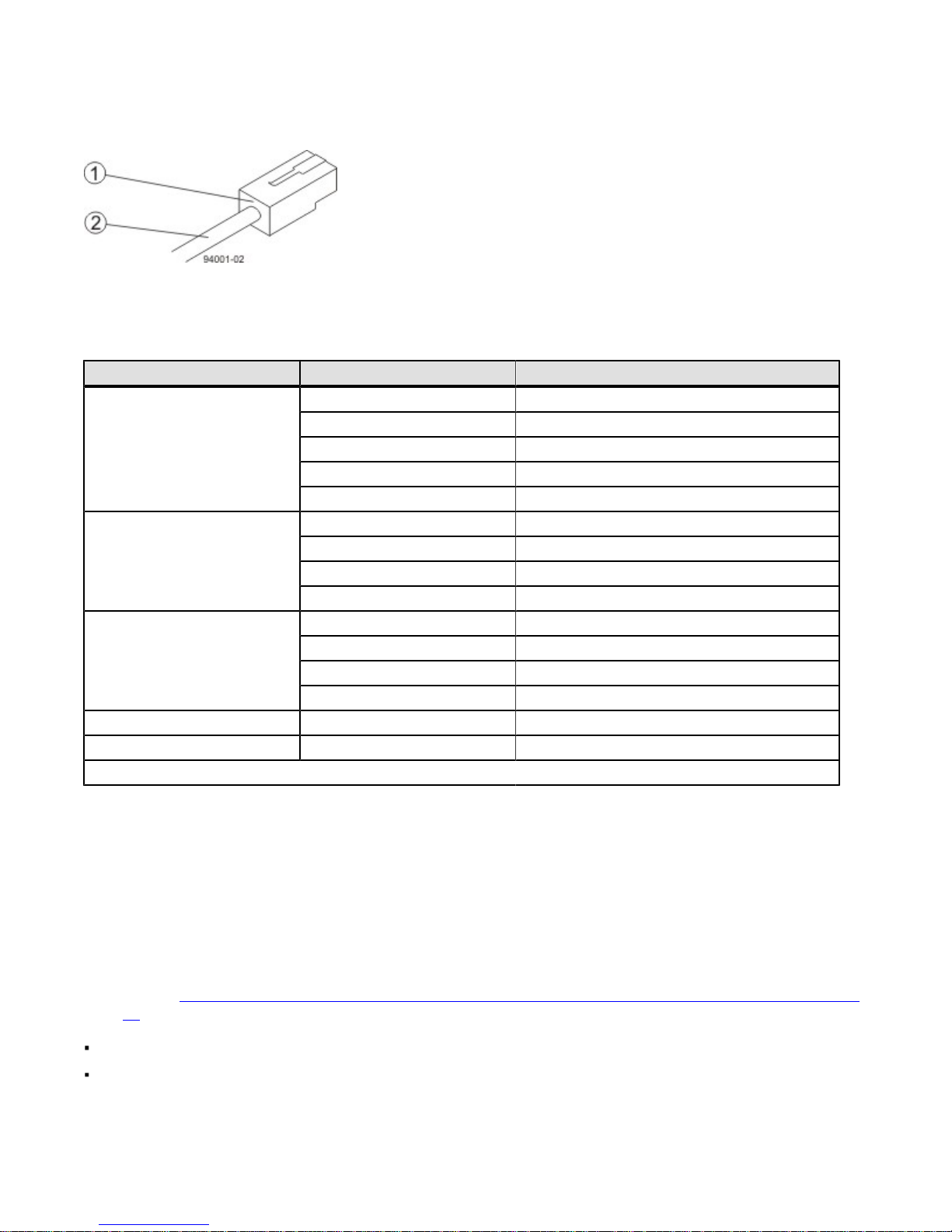
Figure 5. iSCSI Cable with an RJ-45 Connector
1. RJ-45 Connector
2. iSCSI Cable
Table 5. Supported SFP Transceivers*
Vendor Model Version/Data Rate*
Avago
Finisar
JDSU
Molex 74741-0005 1 Gb/s
Opnext TRS2001EN-0001 10 Gb/s
*All SFP Transceivers can connect and run at lower speeds, even though this is not optimal.
AFBR-57D7APZ 8 Gb/s
AFBR-57D9AMZ 8 Gb/s
AFBR-703SDZ 10 Gb/s
AFBR-709SMZ SFP+ 10 GbE/s for iSCSI
AFBR-57F5MZ-NA2 16 Gb/s for FC
FTLF 8521-3 1 Gb/s
FTLF8528P2BCV-LS 8 Gb/s
FTLX8571D3BCL-LS 10 Gb/s
FTLF142P3BNV 16 Gb/s for FC
PLRXPL-VC-SH4-23-N 8 Gb/s
PLRXPL-VC-SH4-NA 8 Gb/s
PLRXPL-SC-S43-22-N 10 Gb/s
PLRXPL-SC-S43-NAe 10 GbE/s
Things to Know – Taking a Quick Glance at the Hardware in a
EF550 Flash Array Configuration
Each drive tray in a storage array must have a minimum of two drives for proper operation.
This section provides an overview of hardware described in this document. For specific details about how LEDs
operate, see “Step 10 – Turning on the Power and Checking for Problems in an EF550 Flash Array Configuration" on
page 51.
The top of the flash array is the side with labels.
The configuration of the host ports might appear different on your system depending on which host interface card
configuration is installed.
215-08288_A0_EF550 Flash Array Installation Guide - 9
Page 14
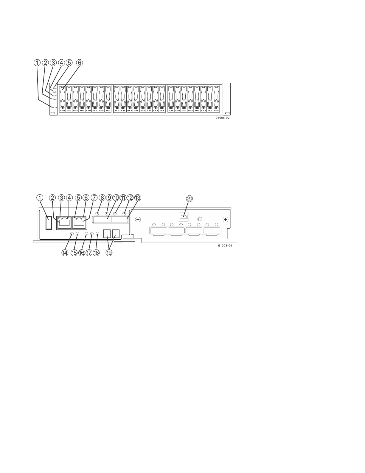
Figure 6. EF550 Flash Array – Front View
1. End Cap Standby Power LED
2. End Cap Power LED
3. End Cap Over-Temperature LED
4. End Cap Service Action Required LED
5. End Cap Locate LED
6. Drive Canister
Figure 7. EF550 Controller with a SAS HIC – Rear View
1. USB Connector
2. 1GbE Management Connector 1
3. 1GbE Link 1 Fault LED
4. 1GbE Link 1 Up LED
5. 1GbE Link 2 Fault LED
6. 1GbE Link 2 Up LED
7. 1GbE Management Connector 2
8. SAS Expansion Link 1 Fault LED
9. SAS Expansion Link 1 Up LED
10. SFF-8088 SAS Connector 1 (Expansion)
11. SAS Expansion Link 2 Fault LED
12. SAS Expansion Link 2 Up LED
13. SFF-8088 SAS Connector 2 (Expansion)
14. Standby Power LED
15. Power-Fan DC Power LED
16. Power-Fan Service Action Allowed LED
17. Power-Fan Service Action Required LED
18. Power-Fan AC Power LED
19. Seven-Segment Display
20. mini USB Port
10 - 215-08288_A0_EF550 Flash Array Installation Guide
Page 15
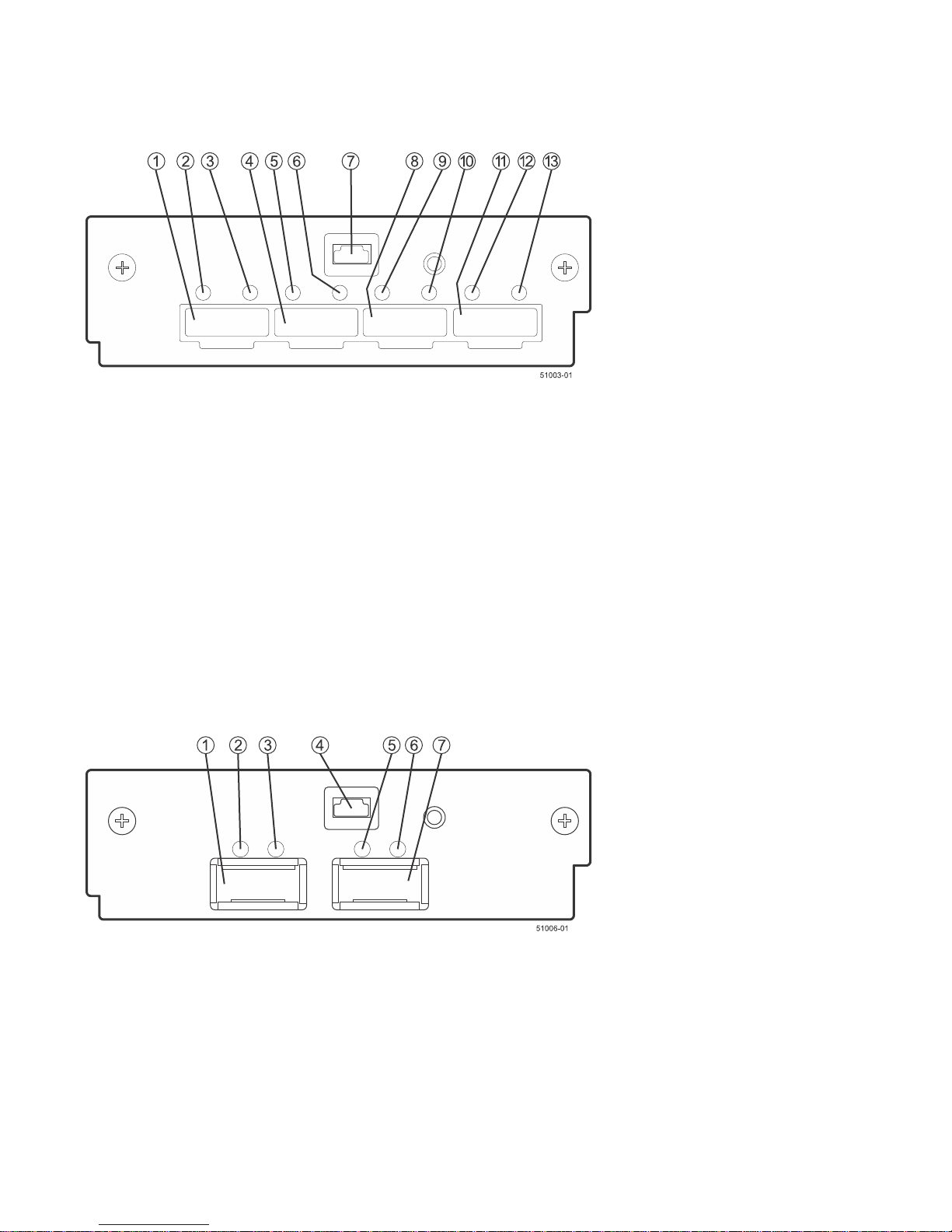
Figure 8. EF550 Right-Rear Subplate with a SAS Host Interface Card
1. SFF-8088 Host Interface Card Channel 1
2. Host Interface Card Link 1 Fault LED
3. Host Interface Card Link 1 Active LED
4. SFF-8088 Host Interface Card Channel 2
5. Host Interface Card Link 2 Fault LED
6. Host Interface Card Link 2 Active LED
7. mini USB Port
8. SFF-8088 Host Interface Card Channel 3
9. Host Interface Card Link 3 Fault LED
10. Host Interface Card Link 3Active LED
11. SFF-8088 Host Interface Card Channel 4
12. Host Interface Card Link 4 Fault LED
13. Host Interface Card Link 4 Active LED
Figure 9. EF550 Right-Rear Subplate with a 40-Gb InfiniBand Host Interface Card
1. Host Interface Card QSFP Channel 1
2. Host Interface Card Logical Link 1Active LED
3. Host Interface Card Physical Link 1 Active LED
4. mini USB Port
5. Host Interface Card Logical Link2 Active LED
6. Host Interface Card Physical Link 2 Active LED
7. Host Interface Card QSFP Channel 2
215-08288_A0_EF550 Flash Array Installation Guide - 11
Page 16
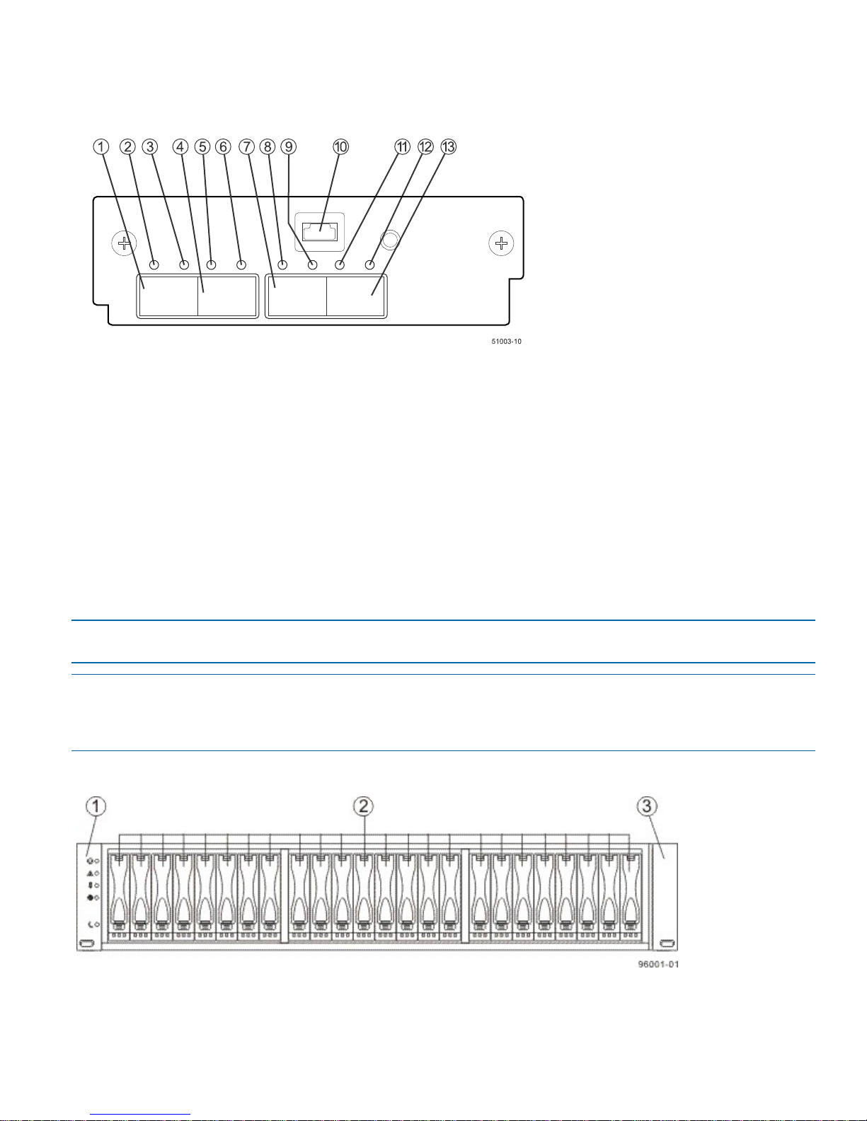
Figure 10. EF550 Right-Rear Subplate with a 16-Gb FC or a 10-Gb iSCSI Host Interface Card
1. SFP+ Host Interface Card Channel 1
2. Host Interface Card Link 1Fault LED
3. Host Interface Card Link 1 Active LED
4. SFP+ Host Interface Card Channel 2
5. Host Interface Card Link 2 Fault LED
6. Host Interface Card Link 2 Active LED
7. SFP+ Host Interface Card Channel 3
8. Host Interface Card Link 3 Fault LED
9. Host Interface Card Link 3 Active LED
10. Mini USB Port
11. Host Interface Card Link 4 Fault LED
12. Host Interface Card Link 4 Active LED
13. SFP+ Host Interface Card Channel 4
ATTENTION Possible equipment damage – You must use the supported drives in the drive tray to ensure proper
operation. For information about supported drives, contact a Customer and Technical Support representative.
ATTENTION Risk of equipment malfunction – To avoid exceeding the functional and environmental limits, install
only drives that have been provided or approved by the original manufacturer. Not all flash arrays are shipped with
pre-populated drives. System integrators, resellers, system administrators, or users of the flash array can install the
drives.
Figure 11. Drive Tray – Front View
1. Left End Cap (Has the Drive Tray LEDs)
2. Drives
3. Right End Cap
12 - 215-08288_A0_EF550 Flash Array Installation Guide
Page 17
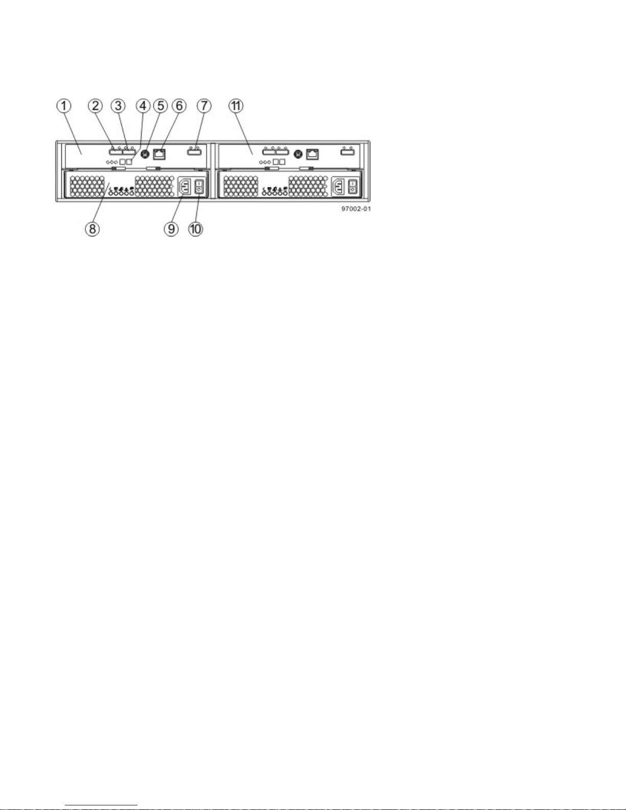
Figure 12. D Drive Tray with AC Power Option – Rear View
1. ESM A Canister
2. Expansion Port SFF-8088 Connector 1 (IN)
3. Expansion Port SFF-8088 Connector 2 (IN)
4. Seven-Segment Display Indicators
5. Serial Port
6. RJ-45 Ethernet Connector
7. Expansion Port SFF-8088 Connector (OUT)
8. Power-Fan Canister
9. Power Connector
10. Power Switch
11. ESM B Canister
Refer to the Storage System Site Preparation Guide for information about the installation requirements of the various
EF550 flash array storage array components.
215-08288_A0_EF550 Flash Array Installation Guide - 13
Page 18
Step 2 – Installing and Configuring the Switches
Things to Know – Switches and Routers
Procedure – Installing and Configuring Switches
Things to Know – Switches and Routers
NOTE Most of the switches and routers, as shipped from the vendor, require an update to either their firmware or
their settings to work correctly with the storage array.
Depending on the configuration of your storage array, you might use either Fibre Channel switches, iSCSI switches,
or InfiniBand switches.
The switches and routers in the following tables are certified for use with an EF550 storage array, an EF550 storage
array, and an EF550 storage array using SANtricity Storage Manager Version 11.10.
If required, make the appropriate configuration changes for each switch or router that is connected to the storage
array.
Refer to the switch’s documentation for information about how to install the switch or router and how to use the
configuration utilities that are supplied with the switch or router.
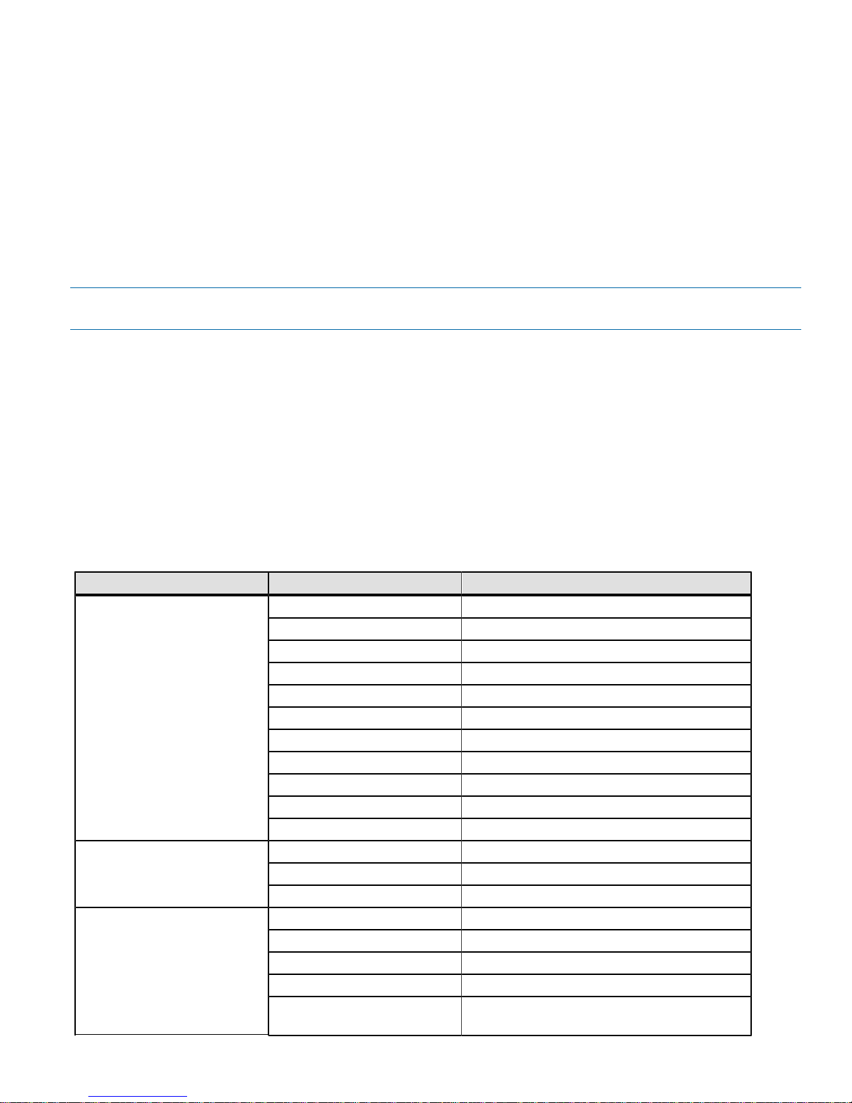
Table 6. Supported FC Switches
Vendor Model Version/Data Rate
Brocade
Qlogic SANbox
Cisco
300 8 Gb/s
5100 8 Gb/s
5300 8 Gb/s
8000 8 Gb/s
DCX 8 Gb/s
DCX-4S 8 Gb/s
48000 8 Gb/s
6505 16 Gb/s
6510 16 Gb/s
6520 16 Gb/s
DCX8510-x 16 Gb/s
3800 8 Gb/s
5800 8 Gb/s
9000 8 Gb/s
9148 8 Gb/s
9506 8 Gb/s
9509 8 Gb/s
9513 8 Gb/s
B-Series 8/24c for HP Blade
Center AJ821B
8 Gb/s
14 - 215-08288_A0_EF550 Flash Array Installation Guide
Page 19
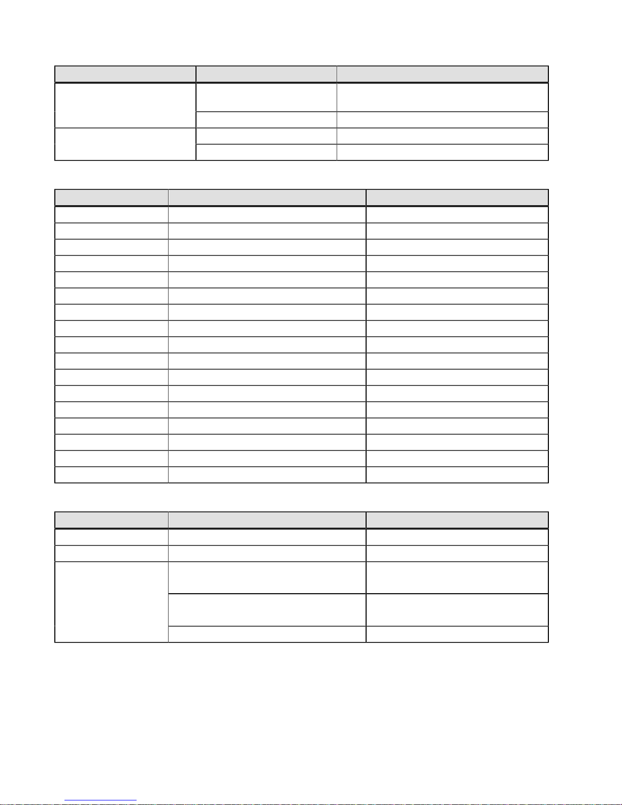
Vendor Model Version/Data Rate
MDS for HP Blade Center
AW564A
9710 16 Gb/s
5010 8 Gb/sCisco Nexus
5020 8 Gb/s
Table 7. Supported InfiniBand Switches
Vendor Model Speed
Mellanox SX6012 Edge Switch 56 Gb/s (FDR)
SX6018 Edge Switch 56 Gb/s (FDR)
SX6036 Edge Switch 56 Gb/s (FDR)
IS5030 Edge Switch 40 Gb/s (QDR)
IS5035 Edge Switch 40 Gb/s (QDR)
4036 Edge Switch 40 Gb/s (QDR)
4036E Edge Switch 40 Gb/s (QDR)
IS5100 Director Switch 40 Gb/s (QDR)
IS5200 Director Switch 40 Gb/s (QDR)
IS5300 Director Switch 40 Gb/s (QDR)
IS5600 Director Switch 40 Gb/s (QDR)
4200 Director Switch 40 Gb/s (QDR)
4700 Director Switch 40 Gb/s (QDR)
SX6506 Director Switch 56 Gb/s (FDR)
SX6512 Director Switch 56 Gb/s (FDR)
SX6518 Director Switch 56 Gb/s (FDR)
SX6536 Director Switch 56 Gb/s (FDR)
8 Gb/s
Table 8. Supported Routers
Vendor Model Speed
Cisco 9222i 8 Gb/s
Brocade 7800 8 Gb/s
Qlogic
Refer to your Technical Support Representative for the latest information about new switches that are tested and
certified to work with various hardware and software combinations.
6240 8 Gb/s FC
6250 8 Gb/s FC
6260 8 Gb/s FC
Procedure – Installing and Configuring Switches
1. Install your switch according to the vendor’s documentation.
10 Gb/s iSCSI
10 Gb/s iSCSI
215-08288_A0_EF550 Flash Array Installation Guide - 15
Page 20
2. Contact your Technical Support Representative to obtain this information:
The latest hardware compatibility information
The models of the switches that are supported
The firmware requirements and the software requirements for the switches
3. Update the switch’s firmware by accessing it from the applicable switch vendor’s website.
This update might require that you cycle power to the switch.
4. Find your switch in the following table to see whether you need to make further configuration changes. Use your
switch’s configuration utility to make the changes.
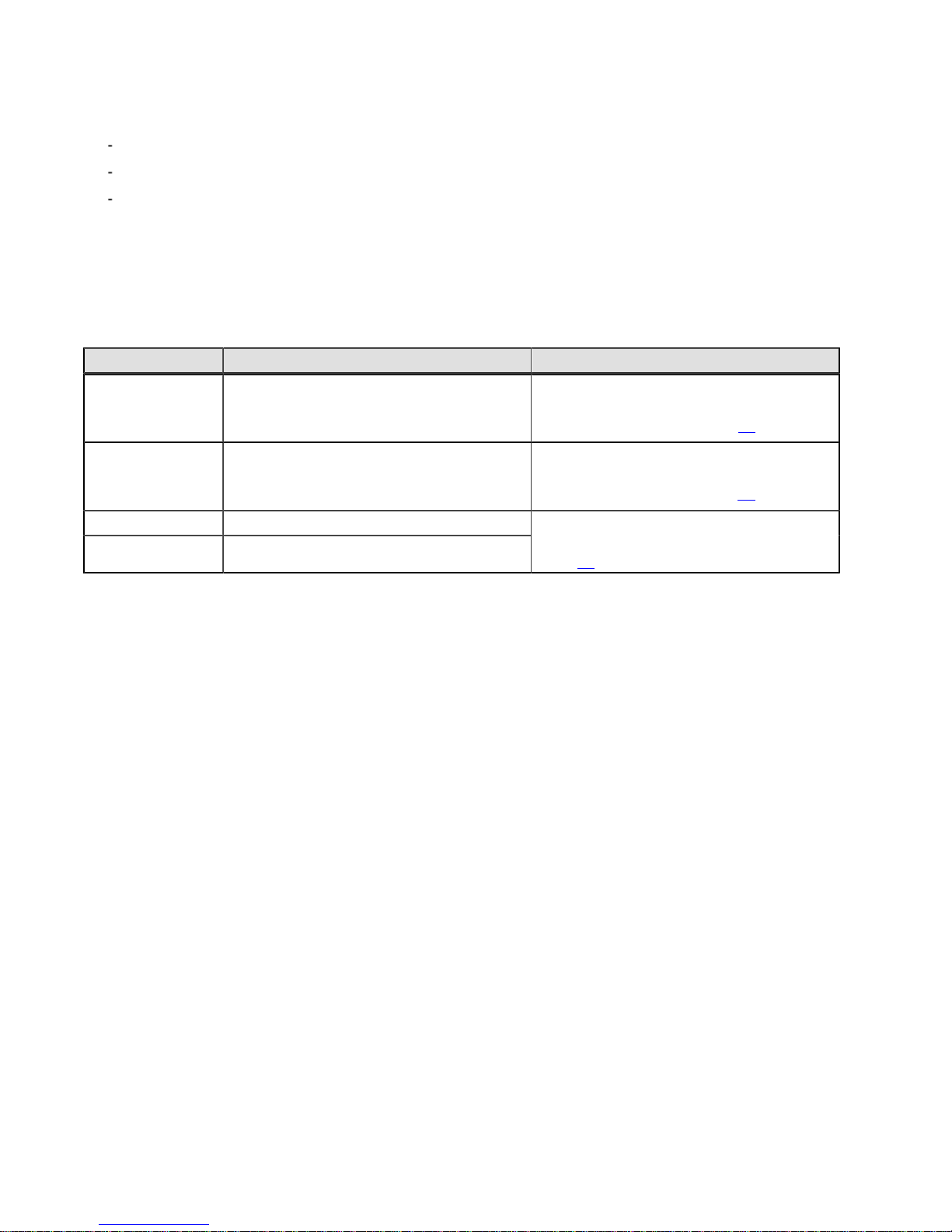
Table 9. Supported Switch Vendors and Required Configuration Changes
Switch Vendor Configuration Changes Required? Next Step
Brocade Yes
Change the In-Order Delivery (IOD) option
to ON.
Cisco Yes
Change the In-Order Delivery (IOD) option
to ON.
Mellanox No
PowerConnect No
Make the change, and go to “Step 3 -Installing the Host Bus Adapters for the
EF550 Flash Array" on page 17.
Make the change, and go to “Step 3 -Installing the Host Bus Adapters for the
EF550 Flash Array” on page 17.
Go to "Step 3 -- Installing the Host Bus
Adapters for the EF550 Flash Array" on
page 17.
16 - 215-08288_A0_EF550 Flash Array Installation Guide
Page 21

Step 3 – Installing the Host Bus Adapters for the EF550 Flash
Array
Key Terms
Things to Know – Host Bus Adapters, Host Channel Adapters, and Ethernet Network Interface Cards
Procedure – Installing Host Bus Adapters
Procedure – Installing Host Channel Adapters
Key Terms
host bus adapter (HBA)
host channel adapter
HBA host port
HBA host port world wide name (WWN)
HCA host port
HCA host port Global Unique Identifier (GUID)
host bus adapter (HBA)
A physical board that resides in the host. The HBA provides for data transfer between the host and the controllers in
the storage array over the I/O host interface. Each HBA contains one or more physical ports.
host channel adapter
TA physical board that resides in the host. The HCA provides for data transfer between the host and the controllers in
a storage array over the InfiniBand I/O host interface. Each HCA contains one or more physical ports.
HBA host port
The physical and electrical interface on the host board adapter (HBA) that provides for the connection between the
host and the controller. Most HBAs have either one or two host ports. The HBA has a unique World Wide Identifier
(WWID) and each HBA host port ha a unique WWID.
HBA host port world wide name (WWN)
A 16-character unique name that is provided for each port on the host bus adapter (HBA).
215-08288_A0_EF550 Flash Array Installation Guide - 17
Page 22

HCA host port
The physical and electrical interface on the host channel adapter (HCA) that provides for the connection between the
host and the controller. Most HCAs have either one or two host ports. The HCA has a Global Unique Identifier (GUID).
HCA host port Global Unique Identifier (GUID)
A 16-character unique name that is provided fore each port on the host channel adapter (HCA).
Things to Know – Host Bus Adapters, Host Channel Adapters,
and Ethernet Network Interface Cards
The EF550 flash array supports host interface cards (HICs) for one of the following:
Four 6-Gb/s SAS host ports
Two 40-Gb/s InfiniBand host ports
Four 10-GB/s iSCSI host ports
Four 16-Gb/s Fibre Channel host ports
The HBAs, HCAs, or NICs on a host must support the type of port (SAS, InfiniBand, iSCSI, or Fibre Channel) to
which they connect on the flash array. For the best performance, the HBAs, HCAs, or NICs should support the
highest data rate supported by the HICs to which they connect.
For maximum hardware redundancy, you must install a minimum of two HBAs, HCAs, or NICs (for either SAS,
InfiniBand, iSCSI or Fibre Channel host connections) in each host. Using both ports of a dual-port HBA, HCA, or
NIC provides two paths to the storage array but does not ensure redundancy if an HBA, HCA, or NIC fails.
NOTE Consult your Technical Support Representative to obtain information about the supported models of the HBAs
and their requirements to make sure you have an acceptable configuration.
Most of the HBA, HCA, or NICs as shipped from the vendor, require updated firmware and software drivers to
work correctly with the storage array. For information about the updates, refer to the Web site of the storage
vendor to obtain certified versions.
Procedure – Installing Host Bus Adapters
1. Check with your Technical Support Representative to make sure you have an acceptable configuration. Before
installing an HBA, you must have the following information:
The latest hardware compatibility information
The models of the HBAs that are supported
The firmware requirements and the software requirements for the HBAs
2. Install your HBA according to the vendor documentation.
18 - 215-08288_A0_EF550 Flash Array Installation Guide
Page 23
NOTE If your operating system is either Windows Server 2008 Server Core, or Windows 2012 Sever, you
might have additional installation requirements. Refer to the Microsoft Developers Network (MSDN) for more
information about Windows Server 2008 Server Core. You can access these resources from www.microsoft.com.
3. Install the latest version of the firmware and software drivers for the HBA. You can find the latest version of the
firmware for the HBA at the storage vendor Web site.
4. Do one of the following:
If the SMagent application is installed on all of your hosts, you have completed this procedure.
If the SMagent application is not installed on all of your hosts, continue with step 5 to obtain the HBA host port
world wide name from the HBA BIOS utility.
5. Reboot or start your host.
6. While your host is booting, look for the prompt to access the HBA BIOS utility.
7. Select each HBA to view its HBA host port world wide name.
8. Record the following information for each host and for each HBA connected to the storage array:
The name of each host
The HBAs in each host
The HBA host port world wide name of each port on the HBA
The following table shows examples of the host and HBA information that you must record.
Table 10. Examples of HBA Host Port World Wide Names
Host Name Associated HBAs HBA Host Port World Wide
Name
ENGINEERING
Vendor x, Model y (dual port) 37:38:39:30:31:32:33:32
37:38:39:30:31:32:33:33
Vendor a, Model y (dual port) 42:38:39:30:31:32:33:42
42:38:39:30:31:32:33:44
Vendor a, Model b (single port) 57:38:39:30:31:32:33:52FINANCE
Vendor x, Model b (single port) 57:38:39:30:31:32:33:53
Procedure – Installing Host Channel Adapters
1. Consult with your Technical Support Representative to verify that you have an acceptable configuration.
Before installing a Host Channel Adapter (HCA) you must have the following information:
The latest hardware compatibility information
The models of the HCAs that are supported
The firmware requirements and the software requirements for the HCAs
2. Install your HCA, including the appropriate version of the firmware, according to the vendor documentation.
3. To get the GUID for each HCA port, run the command ibstat under Linux and look for a line that looks like this:
Port GUID: 0x0002c9030005ca3f.
215-08288_A0_EF550 Flash Array Installation Guide - 19
Page 24
Step 4 – Installing the EF550 Flash Array
Things to Know – General Installation
Procedure – Installing the the EF550 Flash Array
Procedure – Installing Drives in the EF550 Flash Array
Things to Know – General Installation
The power supplies meet standard voltage requirements for both domestic and worldwide operation.
NOTE Make sure that the combined power requirements of your trays do not exceed the power capacity of your
cabinet. For power ratings on EF550 flash arrays and its related drive trays, refer to the Storage System Site
Preparation Guide.
Procedure – Installing the the EF550 Flash Array
WARNING (W08) Risk of bodily injury –
Two persons are required to safely lift the component.
WARNING (W05) Risk of bodily injury – If the bottom half of the cabinet is empty, do not install components
in the top half of the cabinet. If the top half of the cabinet is too heavy for the bottom half, the cabinet might fall and
cause bodily injury. Always install a component in the lowest available position in the cabinet.
You can install the flash array into an industry standard cabinet.
This procedure describes how to install the mounting rails into an industry standard cabinet.
ATTENTION Possible hardware damage – To prevent electrostatic discharge damage to the tray, use proper
antistatic protection when handling tray components.
20 - 215-08288_A0_EF550 Flash Array Installation Guide
Page 25
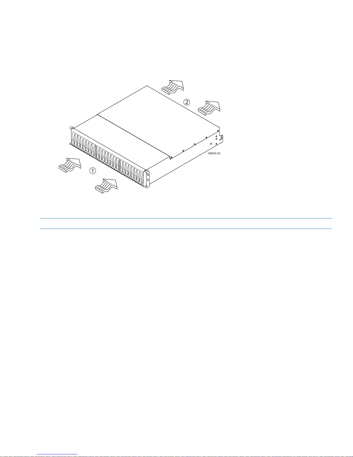
1. Make sure that the cabinet is in the final location. Make sure that the cabinet installation site meets the clearance
requirements (see the figure for "Airflow Direction Through and Clearance Requirements for the EF550 Flash
Array").
Figure 13. EF550 Flash Array Airflow and Clearance Requirements
1. 76 cm (30 in.) clearance in front of the cabinet
2. 61 cm (24 in.) clearance behind the cabinet
NOTE Fans pull air through the tray from front to back across the drives.
2. Lower the feet on the cabinet, if required, to keep it from moving.
3. Remove the flash array and all contents from the shipping carton.
4. Attach the mounting rails to the cabinet.
215-08288_A0_EF550 Flash Array Installation Guide - 21
Page 26
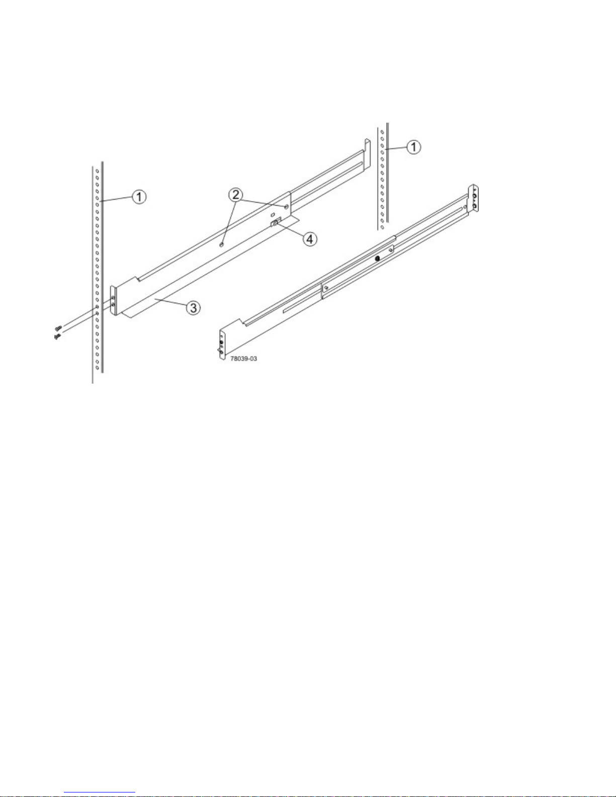
a. Make sure that the adjustment screws on the mounting rail are loose so that the mounting rail can extend or
contract as needed.
Figure 14. Attaching the Mounting Rails to the Cabinet
1. Cabinet Mounting Holes
2. Adjustment Screws for Locking the Mounting Rail Length
3. Mounting Rails
4. Clip for Securing the Rear of the Flash Array
b. Place the mounting rail inside the cabinet, and extend the mounting rail until the flanges on the mounting rail
touch the inside of the cabinet.
c. Make sure that the alignment spacers on the front flange of the mounting rail fit into the mounting holes in the
cabinet.
22 - 215-08288_A0_EF550 Flash Array Installation Guide
Page 27
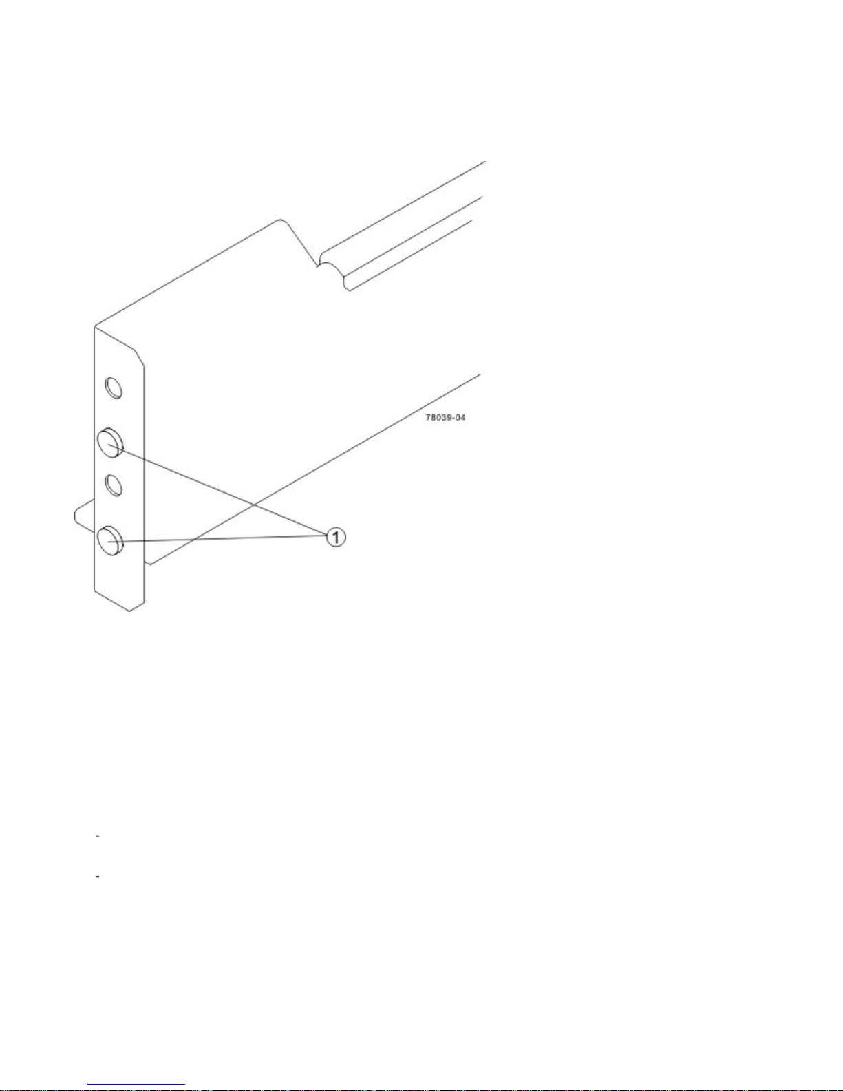
The front flange of each mounting rail has two alignment spacers. The alignment spacers are designed to fit
into the mounting holes in the cabinet. The alignment spacers help position and hold the mounting rail.
Figure 15. Alignment Spacers on the Mounting Rail
1. Alignment Spacers
d. Insert one M5 screw through the front of the cabinet and into the top captured nut in the mounting rail. Tighten
the screw.
e. Insert two M5 screws through the rear of the cabinet and into the captured nuts in the rear flange in the
mounting rail. Tighten the screws.
f. Tighten the adjustment screws on the mounting rail.
g. Repeat substep a through substep f to install the second mounting rail.
5. With the help of one other person, slide the rear of the flash array onto the mounting rails. The rear edge of the
flash array must fit into the clip on the mounting rail. The flash array is correctly aligned when these conditions are
met:
The mounting holes on the front flanges of the drive tray align with the mounting holes on the front of the
mounting rails. Refer to item 4 in the following figure.
The rear edge of the flash array sheet metal fits into the clip on the mounting rail.
215-08288_A0_EF550 Flash Array Installation Guide - 23
Page 28
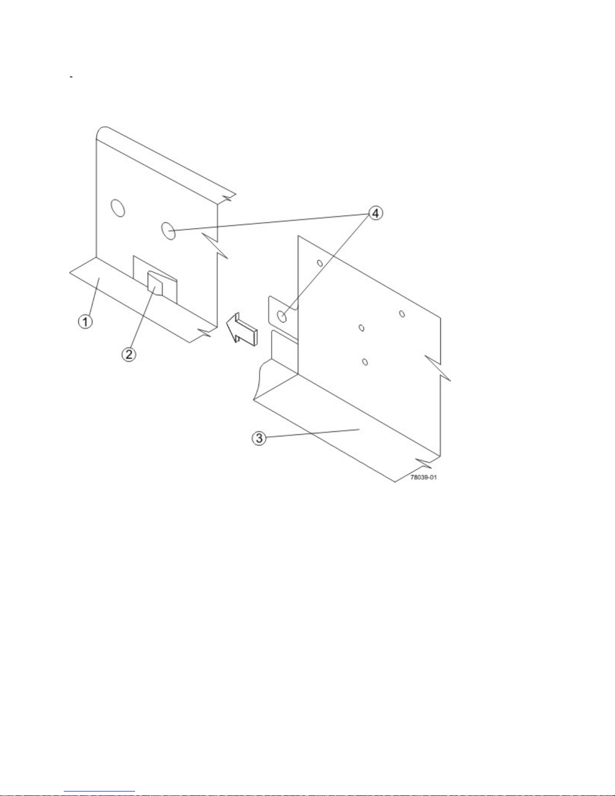
The holes in the flash array sheet metal for the rear hold-down screws align with the captured nuts in the side
of the mounting rails.
Figure 16. Sliding the Flash Array into the Clip on the Mounting Rail
1. Mounting Rail
2. Clip
3. Partial View of the Flash Array Rear Sheet Metal
4. Mounting Holes
6. Secure the front of the flash array to the cabinet. Use the two screws to attach the flange on each side of the front
of the flash array to the mounting rails.
a. Insert one M5 screw through the bottom hole of a flange on the flash array so that the screw goes through the
cabinet rail and engages the bottom captured nut in the mounting rail. Tighten the screw.
24 - 215-08288_A0_EF550 Flash Array Installation Guide
Page 29
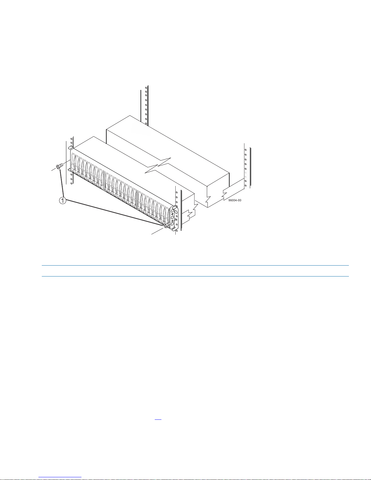
b. Repeat substep a for the second flange.
Figure 17. Securing the EF550 Flash Array to the Cabinet
1. Screw
NOTE The rear of the flash array contains two controllers. The top of the flash array is the side with the labels.
7. Secure the side of the flash array to the mounting rails by performing these substeps:
a. Insert one M4 screw through the side sheet metal of the flash array into the captured nut on the side of the
mounting rail. Tighten the screw.
b. Repeat substep a for the other side.
8. Attach the plastic end caps onto the front of the flash array.
a. Put the top of the end cap on the hinge tab that is part of the flash array mounting flange.
b. Gently press on the bottom of the end cap until it snaps into place over the retainer on the bottom of the flash
array mounting flange.
Procedure – Installing Drives in the EF550 Flash Array
In some situations, the flash array might be delivered without the drives installed. Follow the steps in this procedure to
install the drives. If your flash array already has drives installed, you can skip this step and go to “Step 5 – Connecting
the EF550 Flash Array to the Hosts" on page 27.
215-08288_A0_EF550 Flash Array Installation Guide - 25
Page 30
ATTENTION Risk of equipment malfunction – To avoid exceeding the functional and environmental limits, install
only drives that have been provided or approved by the original manufacturer. Drives might be shipped but not
installed. System integrators, resellers, system administrators, or users can install the drives.
NOTE The installation order is from left to right for the EF550 flash array. The installation order is important because
the drives might already contain configuration information that depends upon the correct sequence of the drives in the
tray.
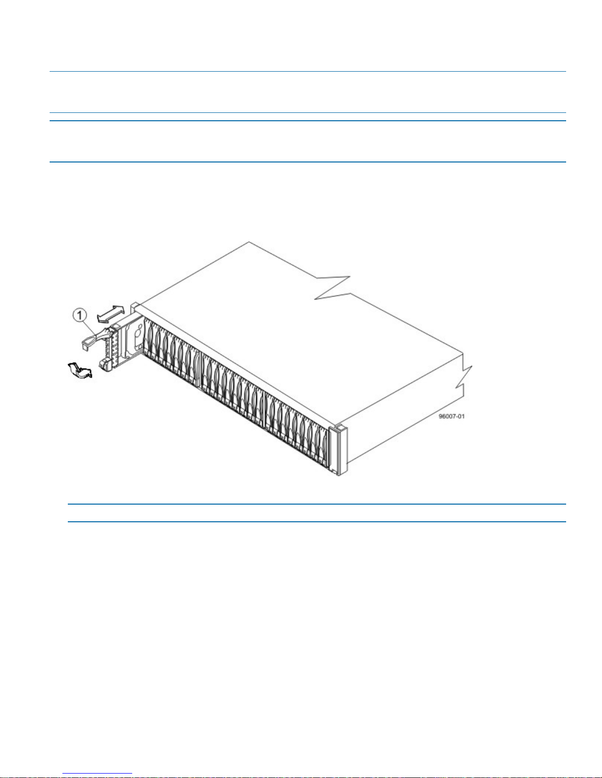
1. Beginning with the first drive slot in the first drive slot on the left side of the EF550 flash array, place the drive on
the slot guides, and slide the drive all the way into the slot.
2. Push the drive handle down to lock the drive securely in place.
Figure 18. Installing a Drive in the EF550 Flash Array
1. Drive Handle
NOTE In some applications, the drive handle might have the hinge on the right.
3. Install the second drive to the right of the first drive.
4. Install the other drives to the right.
26 - 215-08288_A0_EF550 Flash Array Installation Guide
Page 31

Step 5 – Connecting the EF550 Flash Array to the Hosts
Key Terms
Things to Know – Storage Array Configuration Specifications for the EF550 Flash Array
Things to Know – Host Channels
Procedure – Connecting Host Cables on a EF550 Flash Array
Key Terms
topology
direct topology
switch or fabric topology
topology
The logical layout of the components of a computer system or network and their interconnections. Topology deals
with questions of what components are directly connected to other components from the standpoint of being able
to communicate. It does not deal with questions of physical location of components or interconnecting cables. (The
Dictionary of Storage Networking Terminology)
direct topology
A topology that does not use a switch.
switch or fabric topology
A topology that uses a switch.
Things to Know – Storage Array Configuration Specifications for
the EF550 Flash Array
Item Specification
Number of controllers Two
Number of host connectors per
controller
Maximum HBA Host Ports 1024
Maximum SAS HBA logins per
controller
Four SAS host connectors if the SAS HIC is installed.
Two InfiniBand host connectors if the InfiniBand HIC is installed.
Two or Four FC host connectors if the Fibre Channel HIC is installed.
Two or Four iSCSI host connectors if the iSCSI HIC is installed.
128
215-08288_A0_EF550 Flash Array Installation Guide - 27
Page 32
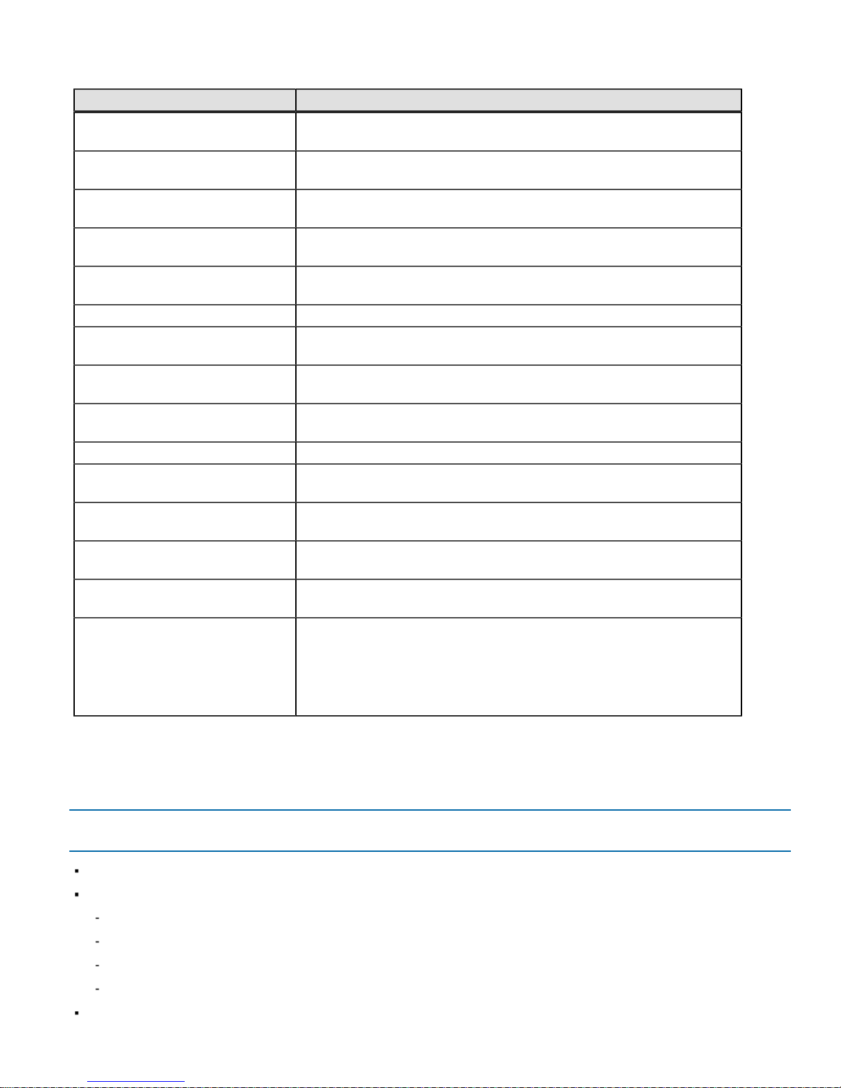
Item Specification
Maximum InfiniBand logins per
controller
Maximum Fibre Channel logins per
controller
SAS HIC Host Port Link Rate (Gb/s)3, 6
256
4096
InfiniBand HIC Host Port Link Rate
(Gb/s)
Fibre Channel HIC Host Port Rate
(Gb/s)
iSCSI HIC Host Port Rate (Gb/s) 1, 10 (auto-negotiated)
Supported Combined Cache and
Processor Memory Sizes
Maximum number of drive trays
supported in a storage array
Maximum number of drive slots
supported
Maximum number of host logins 1024
Maximum number of hosts per
storage partition
Maximum number of volumes per
storage array
Maximum number of storage
partitions
Maximum number of volumes per
storage partition
Cluster support Windows Server 2008 and Windows 2012 operating systems: Windows
40
4, 8, 16
12 GB per controller
4 drive trays
120 SSDs
1024
2048
512
256
Hardware Quality Labs (WHQL) testing.
Solaris 10.U11 with Oracle Solaris Cluster 3.3 U1 and Solaris 11 .1 with
Oracle Solaris Cluster 4.1.
Linux 8.6 with SteelEuye LifeKeeper (SIOS) and Native RH Clustering.
Things to Know – Host Channels
ATTENTION Possible hardware damage – To prevent electrostatic discharge damage to the tray, use proper
antistatic protection when you handle tray components.
The EF550 flash arrays contain no native host ports.
One of the following host interface cards (HICs) is installed on each controller:
Four SAS ports at 6 Gb/s
Two IB ports at 40 Gb/s
Four Fibre Channel ports at 16 Gb/s
Four iSCSI ports at 10 Gb/s
A HIC of the same interface and number of ports must be installed on each controller.
28 - 215-08288_A0_EF550 Flash Array Installation Guide
Page 33
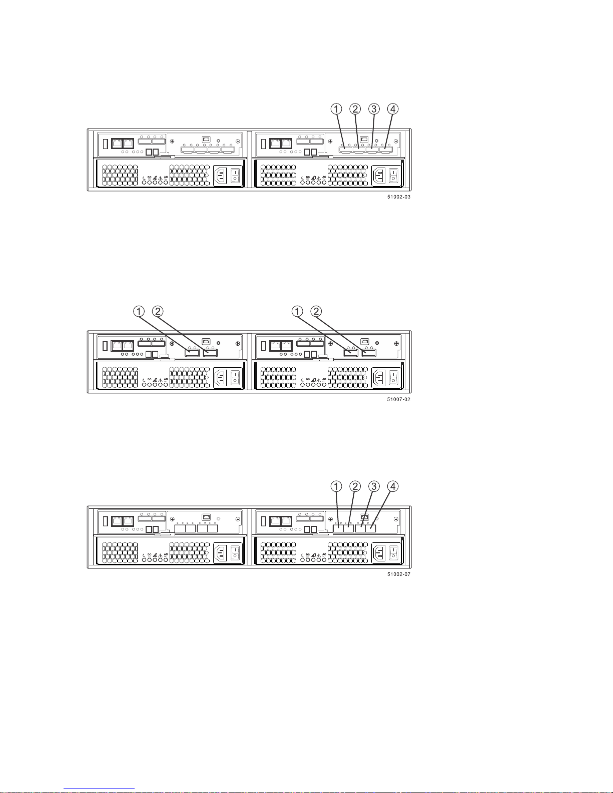
Figure 19. Host Channels on the EF550 Controllers with SAS HIC – Rear View
1. Mini-SAS Host Interface Card Port 1
2. Mini-SAS Host Interface Card Port 2
3. Mini-SAS Host Interface Card Port 3
4. Mini-SAS Host Interface Card Port 4
Figure 20. Host Channels on the EF550 Controllers with an InfiniBand HIC – Rear View
1. QSFP Channel 1
2. QSFP Channel 2
Figure 21. Host Channels on the EF550 Controllers with an FC HIC or an iSCSI HIC– Rear View
1. SFP+ Host Channel 1
2. SFP+ Host Channel 2
3. SFP+ Host Channel 3
4. SFP+ Host Channel 4
Procedure – Connecting Host Cables on a EF550 Flash Array
The type of HICs (SAS, iSCSI, Fibre Channel, or InfiniBand) must match the type of the host bus adapters (HBAs) to
which you connect them.
215-08288_A0_EF550 Flash Array Installation Guide - 29
Page 34
NOTE Make sure that you have installed the HBAs. Refer to “Step 3 – Installing the Host Bus Adapters for the EF550
Flash Array“ on page 17 for information about how to install the HBA and how to use the supplied configuration
utilities.
See the examples in the following section for example cabling patterns.
1. Do one of the following:
If your configuration contains an InfiniBand, Fibre Channel, or iSCSI host interface card and uses optical
cables, start with the first host InfiniBand, Fibre Channel, or iSCSI channel of each controller, and plug one end
of the cable into the QSFP or SFP transceiver in the host channel and go to step 3.
If your configuration uses copper cables, go to step 2.
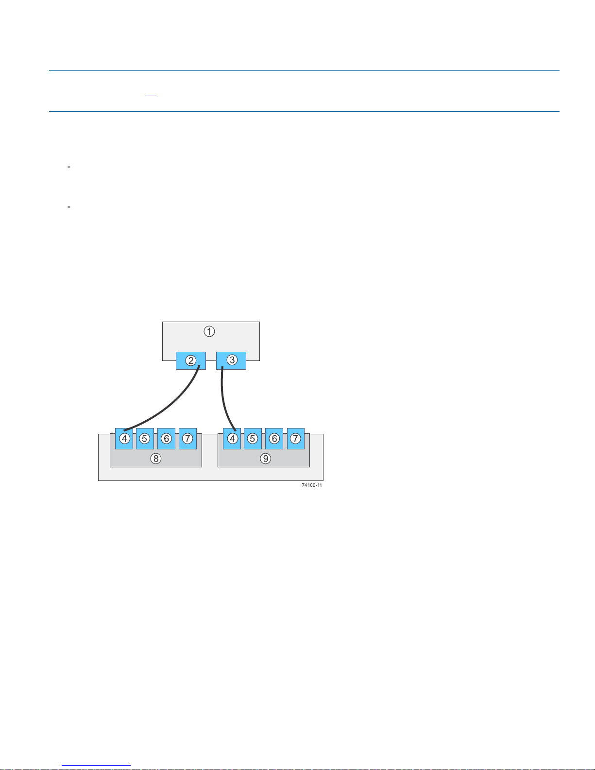
The following four figures display valid host to flash array configurations when using an EF550 flash array.
Figure 22. Direct Topology – One Host and a Dual Flash Array With a Four-Port Connection
1. Host
2. HBA 1 or NIC 1
3. HBA 2 or NIC 2
4. Host Port 1
5. Host Port 2
6. Host Port 3
7. Host Port 4
8. Controller A
9. Controller B
30 - 215-08288_A0_EF550 Flash Array Installation Guide
Page 35
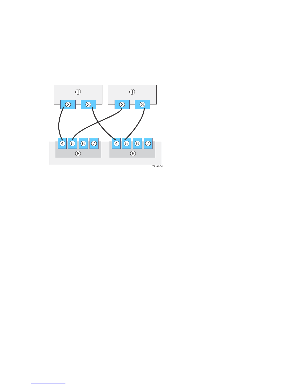
Figure 23. Direct Topology – Two Hosts and a Dual Flash Array With a Four-Port Connection for Maximum
Redundancy
1. Hosts
2. HBA 1 or NIC 1
3. HBA 2 or NIC 2
4. Host Port 1
5. Host Port 2
6. Host Port 3
7. Host Port 4
8. Controller A
9. Controller B
215-08288_A0_EF550 Flash Array Installation Guide - 31
Page 36

Figure 24. Switch or Fabric Topology – Two Hosts and a Dual Flash Array With a Four-Port Connection and a
Zoned Switch
1. Hosts
2. HBA 1 or NIC 1
3. HBA 2 or NIC 2
4. Host Port 1
5. Host Port 2
6. Host Port 3
7. Host Port 4
8. Controller A
9. Controller B
32 - 215-08288_A0_EF550 Flash Array Installation Guide
Page 37
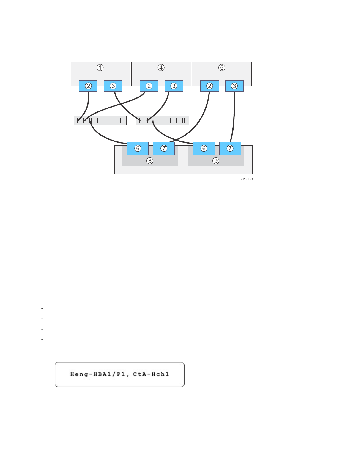
Figure 25. Mixed Topology – Three Hosts and a Dual Flash Array
1. Host 1
2. HBA 1 or NIC 1
3. HBA 2 or NIC 2
4. Host 2
5. Host 3
6. Host Port 1
7. Host Port 2
8. Controller A
9. Controller B
2. Plug either the SAS cable or copper IB cables into the controller.
3. Plug the other end of the cable either into an HBA in the host (direct topology) or into a switch (fabric topology).
4. Affix a label to each end of the cable with this information. A label is very important if you need to disconnect
cables to service a controller. Include this information on the labels:
The host name and the HBA port (for direct topology)
The switch name and the port (for fabric topology)
The controller ID (for example, controller A)
The host channel ID (for example, host channel 1)
Example label abbreviation – Assume that a cable is connected between port 1 in HBA 1 of a host named
Engineering and host channel 1 of controller A. A label abbreviation could be as follows.
5. Repeat step 1 through step 4 for each controller and host channel that you intend to use.
215-08288_A0_EF550 Flash Array Installation Guide - 33
Page 38

Step 6 – Installing the Drive Trays for the EF550 Flash Array
Configurations
Things to Know – General Installation of Drive Trays with the EF550 Flash Array
Procedure – Installing the Drive Trays
Procedure – Installing Drives in the Drive Trays
Things to Know – Connecting the Power Cords
Procedure – Connecting the Power Cords
Things to Know – General Installation of Drive Trays with the
EF550 Flash Array
NOTE If you are installing the drive tray in a cabinet with other trays, make sure that the combined power
requirements of the drive tray and the other trays do not exceed the power capacity of your cabinet.
If you are performing a hot add of a tray to an existing storage array, refer to the Hardware Cabling Guide.
Special site preparation is not required for any of these drive trays beyond what is normally found in a computer
lab environment.
The power supplies meet standard voltage requirements for both domestic and worldwide operation.
Keep as much weight as possible in the bottom half of the cabinet.
Refer to the Storage System Site Preparation Guide for important considerations about cabinet installation.
WARNING (W15) Risk of bodily injury – An empty tray weighs approximately 56.7 kg (125 lb). Three persons
are required to safely move an empty tray. If the tray is populated with components, a mechanized lift is required to
safely move the tray.
Procedure – Installing the Drive Trays
WARNING (W08) Risk of bodily injury –
Two persons are required to safely lift the component.
34 - 215-08288_A0_EF550 Flash Array Installation Guide
Page 39
WARNING (W05) Risk of bodily injury – If the bottom half of the cabinet is empty, do not install components
in the top half of the cabinet. If the top half of the cabinet is too heavy for the bottom half, the cabinet might fall and
cause bodily injury. Always install a component in the lowest available position in the cabinet.
You can install the drive tray into an industry standard cabinet.
This procedure describes how to install the mounting rails into an industry standard cabinet.
ATTENTION Possible hardware damage – To prevent electrostatic discharge damage to the tray, use proper
antistatic protection when handling tray components.
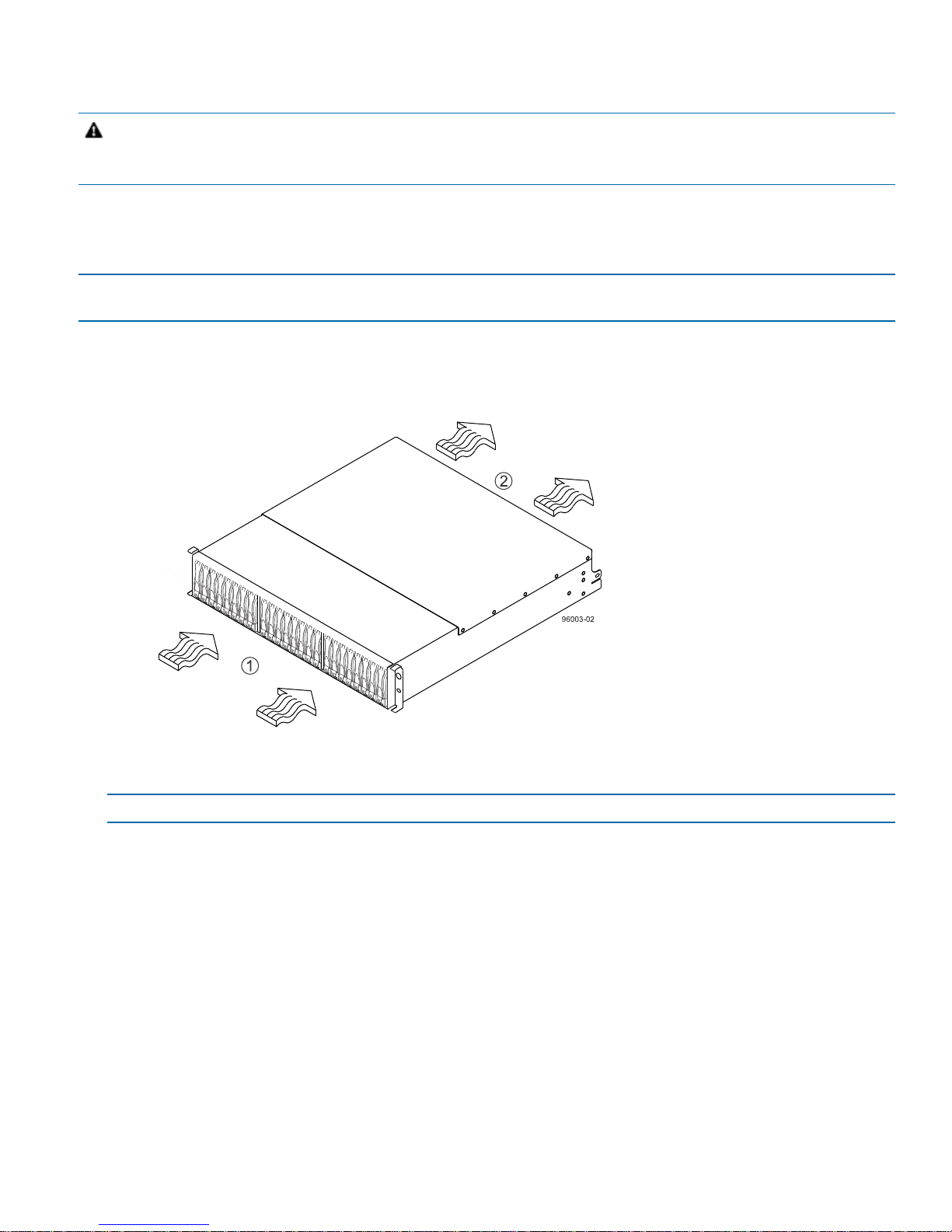
1. Make sure that the cabinet is in the final location. Make sure that you meet the clearance requirements shown in
the following figure.
Figure 26. Drive Tray Airflow and Clearance Requirements
1. 76 cm (30 in.) clearance in front of the cabinet
2. 61 cm (24 in.) clearance behind the cabinet
NOTE Fans pull air through the tray from front to back across the drives.
2. Lower the feet on the cabinet to keep the cabinet from moving.
3. Remove the drive tray and all contents from the shipping carton.
4. Attach the mounting rails to the cabinet.
215-08288_A0_EF550 Flash Array Installation Guide - 35
Page 40
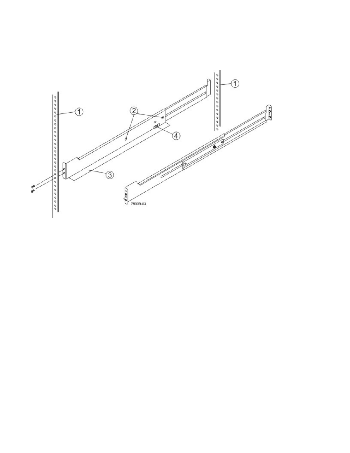
a. Make sure that the adjustment screws on the mounting rail are loose so that the mounting rail can extend or
contract as needed.
Figure 27. Attaching the Mounting Rails to the Cabinet
1. Cabinet Mounting Holes
2. Adjustment Screws for Locking the Mounting Rail Length
3. Mounting Rails
4. Clip for Securing the Rear of the Drive Tray
b. Place the mounting rail inside the cabinet, and extend the mounting rail until the flanges on the mounting rail
touch the inside of the cabinet.
c. Make sure that the alignment spacers on the front flange of the mounting rail fit into the mounting holes in the
cabinet.
36 - 215-08288_A0_EF550 Flash Array Installation Guide
Page 41
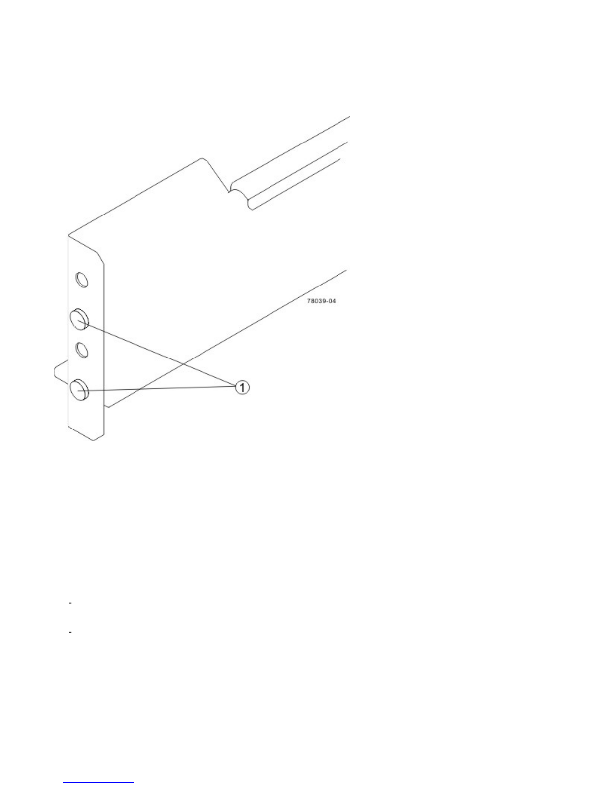
The front flange of each mounting rail has two alignment spacers. The alignment spacers are designed to fit
into the mounting holes in the cabinet. The alignment spacers help position and hold the mounting rail.
Figure 28. Alignment Spacers on the Mounting Rail
1. Alignment Spacers
d. Insert one M5 screw through the front of the cabinet and into the top captured nut in the mounting rail. Tighten
the screw.
e. Insert two M5 screws through the rear of the cabinet and into the captured nuts in the rear flange in the
mounting rail. Tighten the screws.
f. Tighten the adjustment screws on the mounting rail.
g. Repeat substep a through substep f to install the second mounting rail.
5. With the help of one other person, slide the rear of the drive tray onto the mounting rails. The rear edge of the
drive tray must fit into the clip on the mounting rail. The drive tray is correctly aligned when these conditions are
met:
The mounting holes on the front flanges of the drive tray align with the mounting holes on the front of the
mounting rails. Refer to item 4 in the following figure.
The rear edge of the drive tray sheet metal fits into the clip on the mounting rail.
215-08288_A0_EF550 Flash Array Installation Guide - 37
Page 42
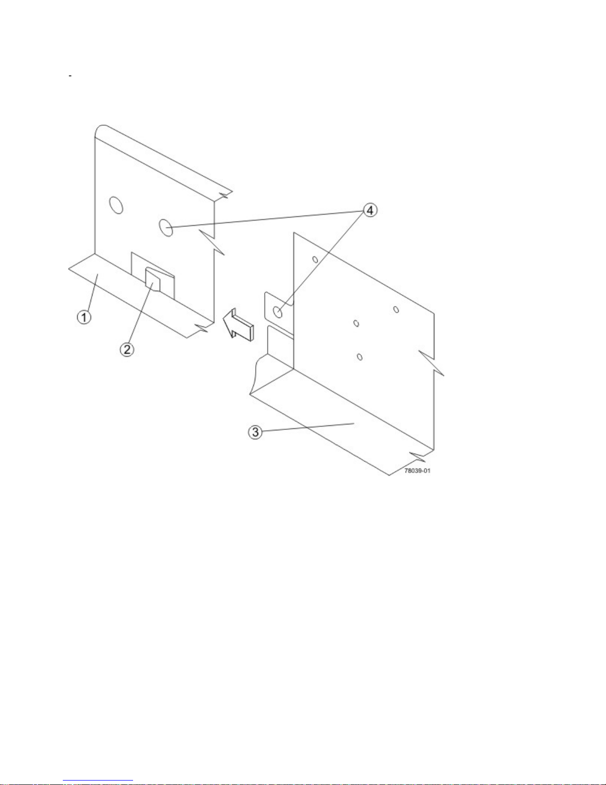
The holes in the drive tray sheet metal for the rear hold-down screws align with the captured nuts in the side of
the mounting rails.
Figure 29. Sliding the Drive Tray into the Clip on the Mounting Rail
1. Mounting Rail
2. Clip
3. Partial View of the Drive Tray Rear Sheet Metal
4. Mounting Holes
6. Secure the front of the drive tray to the cabinet. Use the two screws to attach the flange on each side of the front of
the drive tray to the mounting rails.
a. Insert one M5 screw through the bottom hole of a flange on the drive tray so that the screw goes through the
cabinet rail and engages the bottom captured nut in the mounting rail. Tighten the screw.
38 - 215-08288_A0_EF550 Flash Array Installation Guide
Page 43
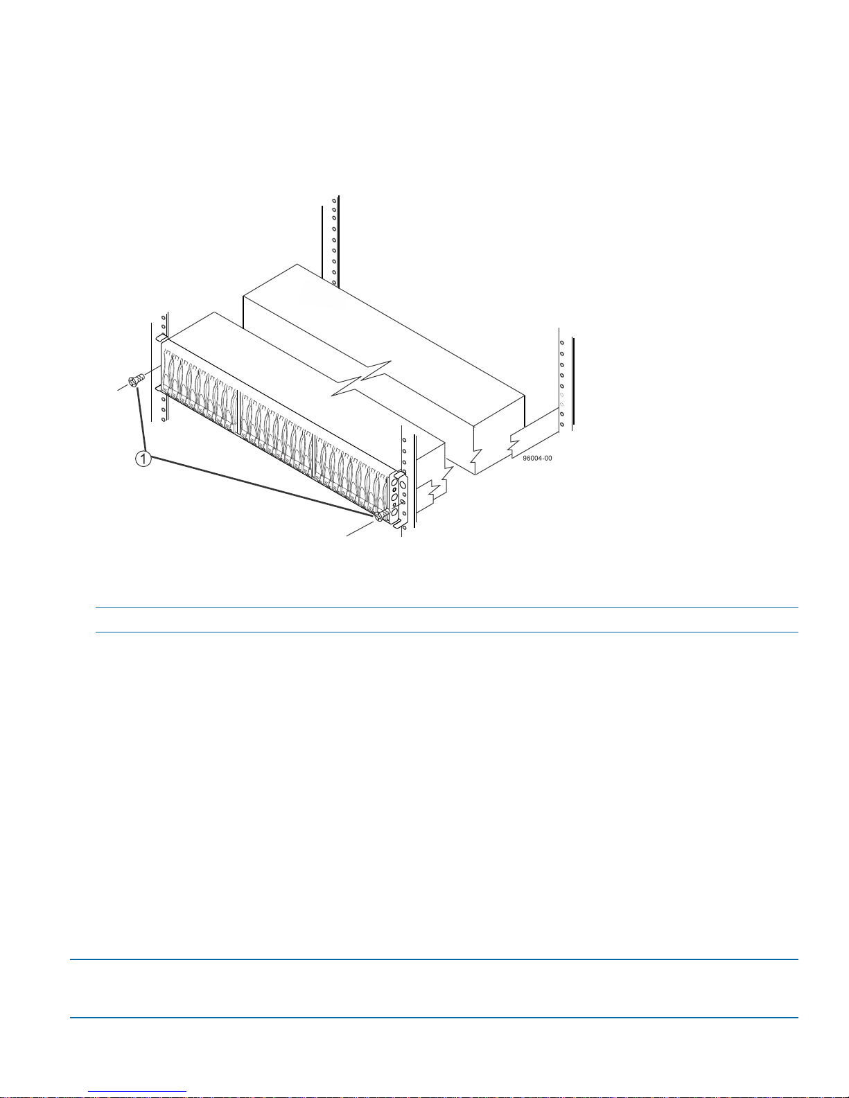
b. Repeat substep a for the second flange.
Figure 30. Securing the Drive Tray to the Cabinet
1. Screw
NOTE The rear of the flash array contains two controllers. The top of the flash array is the side with the labels.
7. Secure the side of the drive tray to the mounting rails by performing these substeps:
a. Insert one M4 screw through the side sheet metal of the drive tray into the captured nut on the side of the
mounting rail. Tighten the screw.
b. Repeat substep a for the other side.
8. Attach the plastic end caps onto the front of the drive tray.
a. Put the top of the end cap on the hinge tab that is part of the drive tray mounting flange.
b. Gently press on the bottom of the end cap until it snaps into place over the retainer on the bottom of the drive
tray mounting flange.
Procedure – Installing Drives in the Drive Trays
In some situations, the drive tray might be delivered without the drives installed. Follow the steps in this procedure to
install the drives.
ATTENTION Risk of equipment malfunction – To avoid exceeding the functional and environmental limits, install
only drives that have been provided or approved by the original manufacturer. Drives might be shipped but not
installed. System integrators, resellers, system administrators, or users can install the drives.
215-08288_A0_EF550 Flash Array Installation Guide - 39
Page 44
NOTE The installation order is from top to bottom and from left to right for the DE1600 drive tray, and left to right
for the DE5600 drive tray. The installation order is important because the drives might already contain configuration
information that depends upon the correct sequence of the drives in the tray.
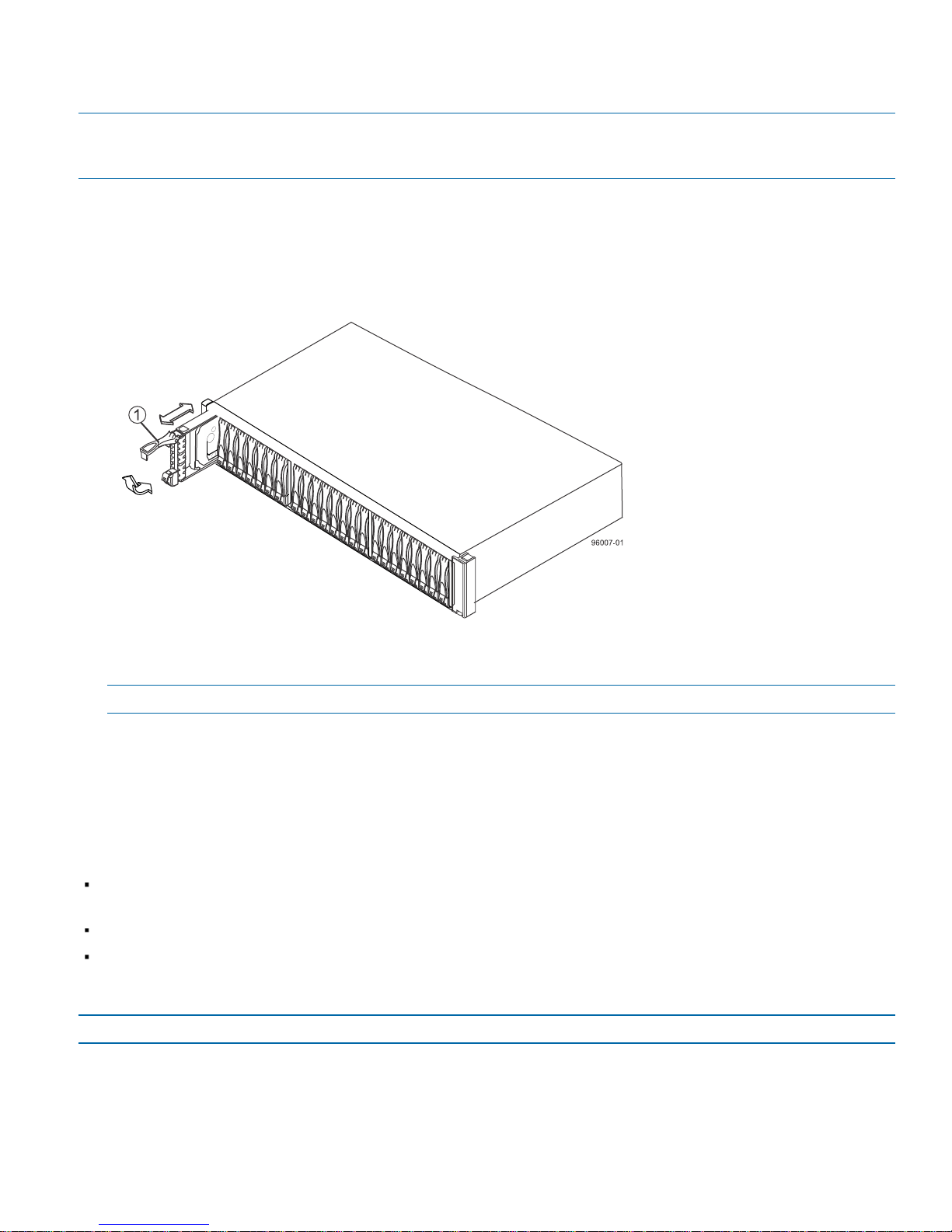
1. Beginning with first drive slotdrive on the left side of the drive tray, place the drive on the slot guides, and slide the
drive all the way into the slot.
2. Push the drive handle down to lock the drive securely in place.
Figure 31. Installing a Drive in the Drive Tray
1. Drive Handle
NOTE In some applications, the drive handle might have the hinge on the right.
3. Install the second drive to the right of the first drive.
4. Install the other drives to the right.
Things to Know – Connecting the Power Cords
For each AC power connector on the drive tray, make sure that you use a separate power source in the cabinet.
Connecting to independent power sources maintains power redundancy.
To ensure proper cooling and assure availability, the drive tray always uses two power supplies.
You can use the power cords shipped with the drive tray with typical outlets used in the destination country, such
as a wall receptacle or an uninterrupted power supply (UPS). These power cords, however, are not intended for
use in most EIA-compliant cabinets.
NOTE Make sure that you do not turn on the power to the drive tray until this installation guide instructs you to do so.
40 - 215-08288_A0_EF550 Flash Array Installation Guide
Page 45

Procedure – Connecting the Power Cords
1. Make sure that the circuit breakers in the cabinet are turned off.
2. Make sure that both of the Power switches on the drive trays are turned off.
3. Connect the primary power cords from the cabinet to the external power source.
215-08288_A0_EF550 Flash Array Installation Guide - 41
Page 46

Step 7 – Connecting the EF550 Flash Array to the Drive Trays
Use this step to cable the EF550 flash array and related drive trays. For additional information, be sure to consult the
Hardware Cabling Guide.
Key Terms
Things to Know – EF550 Flash Array
Things to Know – Drive Trays
Things to Know – Drive Tray Cabling Configurations for the EF550 Flash Array
Procedure – Connecting the Drive Trays to the EF550 Flash Array
Key Terms
drive channel
drive channel
The path for the transfer of data between the controllers and the drives in the storage array.
Things to Know – EF550 Flash Array
The EF550 flash arrays supports the drive trays for expansion.
For any one flash array, you must not exceed the limit is 120 drives. The drive limit includes drives installed in the
flash array.
Each controller has two SAS expansion connectors that must both be connected (one to the ESM A side and the
other to the ESM B side) to the drive tray to ensure path redundancy.
NOTE Make sure that you do not turn on the power to the drive tray until this installation guide instructs you to do so.
For the correct procedure for turning on the power, see “Step 10 – Turning on the Power and Checking for Problems
in an EF550 Flash Array Configuration" on page 51.
42 - 215-08288_A0_EF550 Flash Array Installation Guide
Page 47
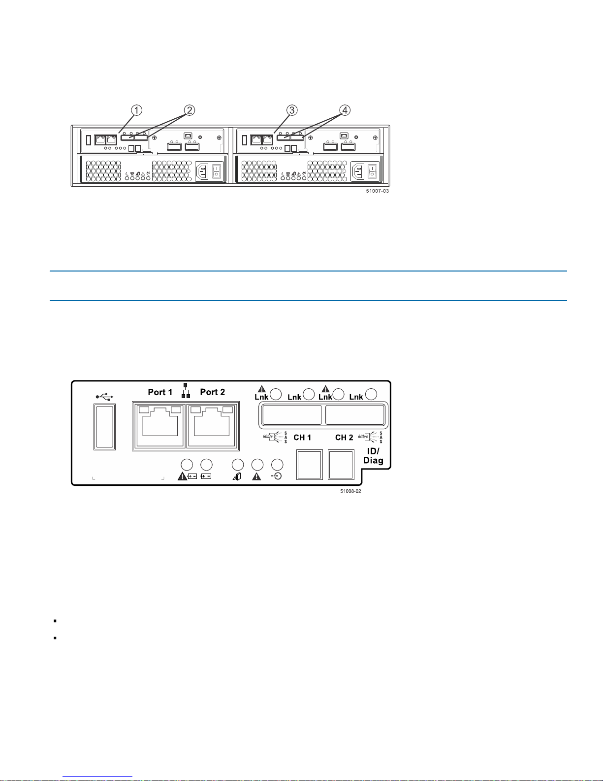
Figure 32. Drive Channel Ports on the EF550 Flash Array
1. Controller Canister A
2. SFF-8088 SAS Channels (Drive Expansion)
3. Controller Canister B
4. SFF-8088 SAS Channels (Drive Expansion)
NOTE To maintain data access in the event of the failure of a controller, an ESM, or a drive channel, you must
connect a drive tray or a string of drive trays to both drive channels on a redundant path pair.
Figure 33. EF550 Controller with Drive Channel Ports (CH1 and CH2)
Things to Know – Drive Trays
Each drive tray can contain a maximum of twenty-four 6.35-cm (2.5-in.) drives.
Each ESM in the drive tray contains a pair of SAS In connectors and one SAS Expansion (Out) connector.
215-08288_A0_EF550 Flash Array Installation Guide - 43
Page 48
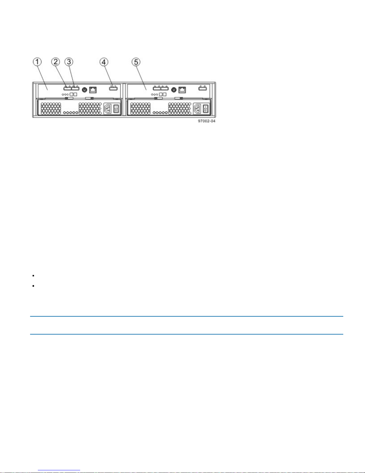
Figure 34. Drive Tray – Rear View
1. ESM A
2. SAS IN Connector
3. SAS IN Connector
4. SAS Expansion (Out) Connector
5. ESM B
Things to Know – Drive Tray Cabling Configurations for the
EF550 Flash Array
The figures in this section show representative cabling configurations. The configurations shown guarantee that
redundant data paths exist between the flash array and all attached drive trays in a storage array. You can attach the
EF550 flash array to a maximum of four drive trays.
For EF550 flash array cabling, make sure that both controllers have access to all available drive trays by making sure
that:
Expansion port 1 from both controllers is connected to the same ESM in slot A of the first drive tray in the stack.
Expansion port 2 from both controllers is connected to the same ESM in slot B of the last drive tray in the stack.
Except for the ESMs connected directly to the controllers and the last ESMs in the stack, each ESM should have only
a single connection to the ESM that follows it.
NOTE On the EF550 flash array models, the expansion connectors to the drive trays are always on the left side of
the controllers from the rear view.
44 - 215-08288_A0_EF550 Flash Array Installation Guide
Page 49
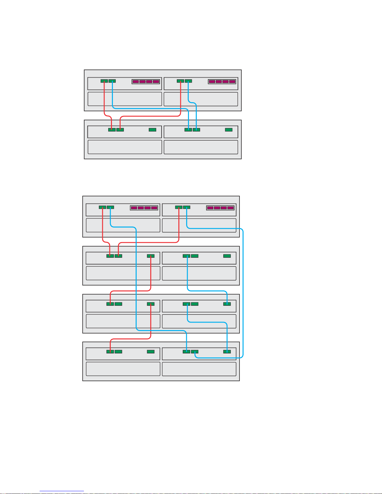
Figure 35. One EF550 Flash Array and One Drive Tray
74198-13
Drive Tray
EF550
74198-14
Drive Tray
Drive Tray
Drive Tray
EF550
Figure 36. One EF550 Flash Array and Three Drive Trays
Procedure – Connecting the Drive Trays to the EF550 Flash Array
You need four SAS cables to attach one drive tray to the flash array. For each additional drive tray, you need two
more SAS cables. These general rules apply:
215-08288_A0_EF550 Flash Array Installation Guide - 45
Page 50

Expansion Channel 1 from both controllers must be connected to the same ESM A of the first drive tray in the
drive tray stack. Expansion Channel 2 from both controllers must be connected to the same ESM B of the last
drive tray in the drive tray stack.
The expansion channels must not be connected together: Do not connect a cable between ESM A of a drive tray
to ESM B of another drive tray.
SAS channels are not tolerant of loops. Except for the ESM connected directly to the controllers, each ESM should
only have a single connection to the ESM before it and a single connection to the ESM that follows it (unless it is
the last ESM in the channel). Do not connect additional cables to ESMs to provide short-cut paths because this
step creates a loop in the topology.
The drive trays in the chain of connections from controller A are in the reverse order from those whose
connections start from controller B. That is, the last drive tray in the chain from controller A must be the first drive
tray in the chain from controller B.
NOTE It does not matter which of the two SAS In ports on an ESM you use for a connection, but it is best to follow
the conventions described in the documentation so your storage management software represents the storage array
consistently.
NOTE Some SAS ports might have a black plastic plug installed. Remove the plug before you attach a cable to the
port.
As you install each cable, attach labels to the cable with the following information:
The controller ID (for example, controller A)
The ESM ID (for example, ESM A)
The ESM connector (In or Out)
The drive tray ID
For example, if you are connecting controller A to the SAS In port on ESM A in drive tray 1, the label on the controller
end of the cable will have this information:
CtA-Dch1, Dm1-ESM_A (left), In – Controller End
The label on the drive tray end of the cable will have this information:
Dm1-ESM_A (left), In, CtrlA
If you are connecting an ESM (Out) port to an ESM (In) port, the label on the first drive tray will have this information:
Dm1-ESM_A (left), OUT, DM2 ESM_A (left)
1. Attach a cable between the SAS Expansion (Ch1) connector on controller A in the flash array and a SAS In
connector on ESM A in the first drive tray.
2. Attach a cable between the SAS Expansion (Ch 1) connector on controller B in the flash array and the second
SAS In connector on ESM A in the first drive tray.
3. Are you adding more drive trays?
Yes – Go to step 4.
No – Go to step 6.
4. Attach a cable between the SAS Expansion (Out) connector on ESM A of the previous drive tray that you cabled
and a SAS In connector on ESM A in the next drive tray.
5. Are you adding more drive trays?
46 - 215-08288_A0_EF550 Flash Array Installation Guide
Page 51

Yes – Go to step 4.
No – Go to step 6.
6. Attach a cable between the SAS Expansion (CH2) connector on controller Ain the flash array and a SAS In
connector on ESM B in the last drive tray.
7. Attach a cable between the SAS Expansion (Ch2) connector on controller B in the flash array and the second SAS
In connector on ESM B in the last drive tray (in reverse order from step 3).
8. Do one of the following:
If there are no more drive trays in the storage array, you are done.
If there are more drive trays, attach a cable between the SAS Expansion (CH2) connector on ESM B of the
previous drive tray that you cabled and a SAS In connector on ESM B in the next drive tray (in reverse order
from step 3) and continue with step 9.
9. Return to step 8.
215-08288_A0_EF550 Flash Array Installation Guide - 47
Page 52

Step 8 – Connecting the Ethernet Cables
Use this step if you are using out-of-band management for your flash array. If you use in-band management, you can
ignore this step and continue with "Step 9 – Connecting the Power Cords" on page 50.
Key Terms
Things to Know – Connecting Ethernet Cables
Procedure – Connecting Ethernet Cables
Key Terms
in-band management
out-of-band management
in-band management
A method to manage a storage array in which a storage management station sends commands to the storage array
through the host input/output (I/O) connection to the controller. The SMagent must be installed for this method to work
correctly.
out-of-band management
A method to manage a storage array in which a storage management station sends commands to the storage array
through the Ethernet connections on the controller. This is the recommended management method.
Things to Know – Connecting Ethernet Cables
This topic concerns Ethernet management connections, not the Ethernet iSCSI connections that might be used
through a host interface card connection.
ATTENTION Risk of security breach – Connect the Ethernet ports on the flash array to a private network segment
behind a firewall. If the Ethernet connection is not protected by a firewall, your flash array might be at risk of being
accessed from outside of your network.
Ethernet port 2 on each controller is reserved for access by Technical Support.
Because the controllers support the Auto-MDIX feature, you do not need an Ethernet crossover cable.
This topic concerns Ethernet management connections, not the Ethernet iSCSI connections that might be used
through a host interface card connection.
48 - 215-08288_A0_EF550 Flash Array Installation Guide
Page 53

Procedure – Connecting Ethernet Cables
Perform these steps to connect Ethernet cables for out-of-band management.
1. Connect one end of an Ethernet cable into the Ethernet port 1 on controller A.
2. Connect the other end to the applicable network connection.
3. Repeat step 1 through step 2 for controller B.
215-08288_A0_EF550 Flash Array Installation Guide - 49
Page 54
Step 9 – Connecting the Power Cords
Use the following information to connect the power cords in your storage array.
Things to Know – AC Power Cords
Procedure – Connecting AC Power Cords
Things to Know – AC Power Cords
For each AC power connector on the drive tray, make sure that you use a separate power source in the cabinet.
Connecting to independent power sources maintains power redundancy.
To ensure proper cooling, do not operate a drive tray with one of its power supplies removed.
You can use the power cords shipped with the flash array with typical outlets used in the destination country, such
as a wall receptacle or an uninterrupted power supply (UPS). These power cords, however, are not intended for
use in most EIA-compliant cabinets.
Procedure – Connecting AC Power Cords
1. Make sure that the circuit breakers in the cabinet are turned off.
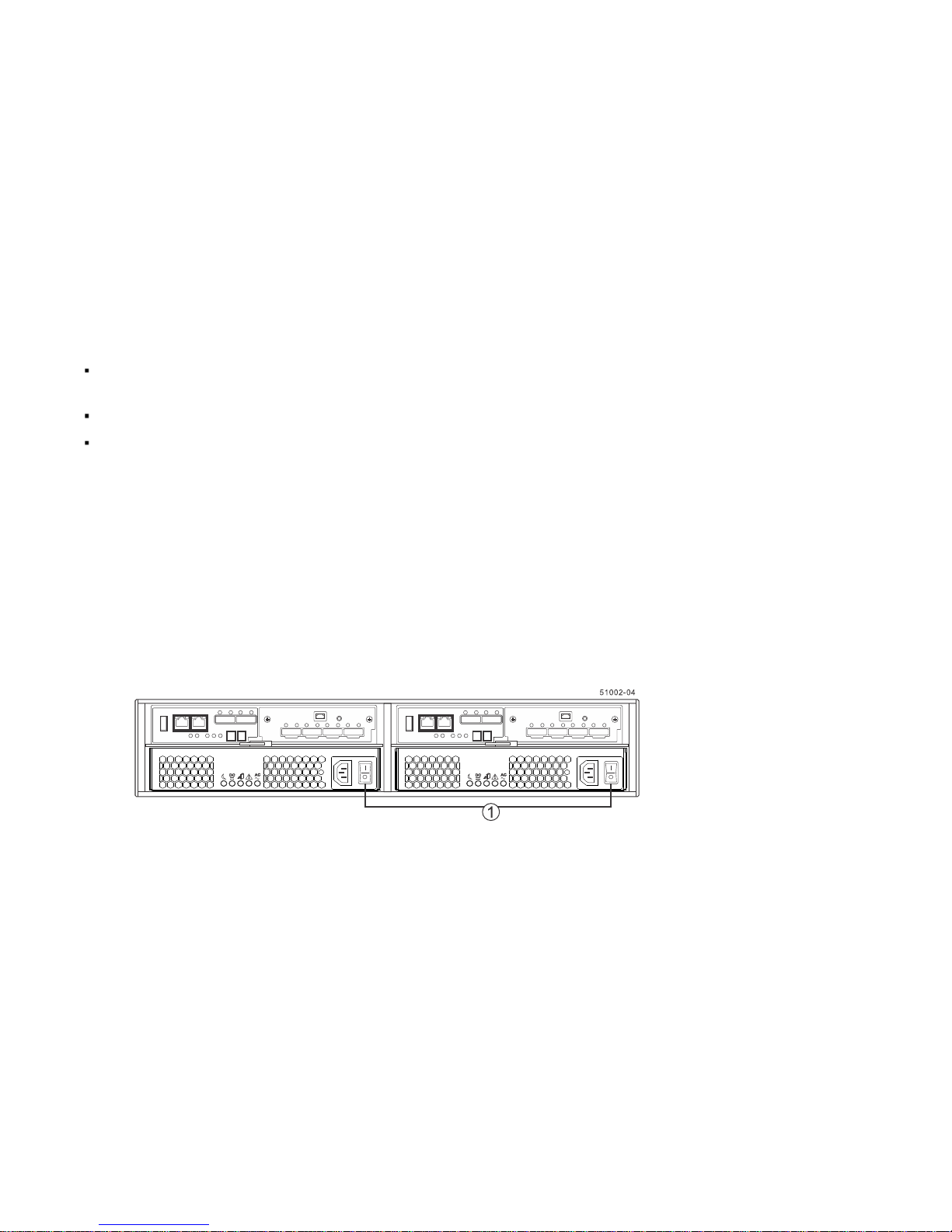
2. Make sure that both of the Power switches on the flash array are turned off.
Figure 37. Power Switches on the EF550 Flash Array
1. Power Switches
3. Connect the primary power cords from the cabinet to the external power source.
4. Connect a cabinet interconnect power cord (or power cords specific to your particular cabinet) to the AC power
connector on each power canister in the drive tray.
5. If you are installing other drive trays in the cabinet, connect a power cord to each power canister in the drive trays.
50 - 215-08288_A0_EF550 Flash Array Installation Guide
Page 55

Step 10 – Turning on the Power and Checking for Problems in an
EF550 Flash Array Configuration
After you complete this task, you can install the software and perform basic configuration tasks on your storage array.
Continue with the Initial Configuration and Software Installation.
Procedure –Turning On the Power to the Storage Array and Checking for Problems in a EF550 Flash Array
Configuration
Things to Know – LEDs on the EF550 Flash Array or the EF550 Flash Array
Things to Know – General Behavior of the LEDs on the Flash Array
Things to Know – Service Action Allowed LEDs
Things to Know – LEDs on the Drive Tray
General Behavior of the LEDs on the Drive Trays
Things to Know – Seven Segment Display Sequence Code Definitions on the EF550 Flash Array
Things to Know – Seven-Segment Component Failure Identifications for the EF550 Flash Array
Things to Know – Lock-Down Codes for the Flash Array
Things to Know – Seven-Segment Display Use Cases
Things to Know – Seven-Segment Display for the ESMs on the Drive Trays
Procedure –Turning On the Power to the Storage Array and
Checking for Problems in a EF550 Flash Array Configuration
NOTE If you are running a EF550 flash array that has either DE1600 drive trays or DE5600 drive trays, the flash
arraymust have a 725-watt power supply. If the EF550 flash array contains a 585-watt power supply, the controllers
lock down and your storage array is not operational.
You must turn on the power to all of the connected drive trays before you turn on the power for the flash array.
Performing this action makes sure that the controllers recognize each attached drive tray.
NOTE While the power is being applied to the trays, the LEDs on the front and the rear of the trays come on and go
off intermittently.
1. Turn on both Power switches on each drive tray that is attached to the flash array. Depending on your
configuration, it can take several minutes for each drive tray to complete the power-on process.
Before you go to step 2, check the LEDs on the drive trays to verify that the power was successfully applied to all
of the drive trays. Wait 30 seconds after turning on the power to the drive trays and wait for all the drives to come
online (persistent green LEDs) before turning on the power to the flash array.
2. Turn on both Power switches on the rear of the flash array. Depending on your configuration, it can take several
minutes for the flash array to complete the power-on process.
3. Check the LEDs on the front and the rear of the flash array and the attached drive trays.
4. If you see any amber LEDs, make a note of their location.
215-08288_A0_EF550 Flash Array Installation Guide - 51
Page 56
Things to Know – LEDs on the EF550 Flash Array or the EF550
Flash Array
The following topics provide details on the LEDs found on the EF550 flash array or the EF550 flash array.
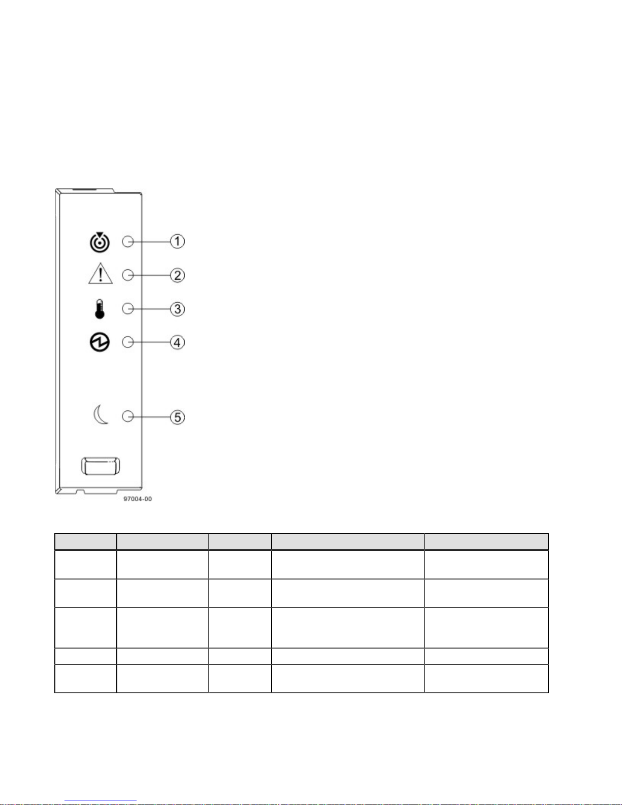
LEDs on the Left End Cap
Figure 38. LEDs on the Left End Cap
Table 11. LEDs on the Left End Cap
Location LED Color On Off
1 Flash Array Locate White Identifies a flash array that you
2 Service Action
Required
3 Flash Array Over-
Temperature
4 Power Green Power is present. Power is not present.
5 Standby Power Green The flash array is in Standby
52 - 215-08288_A0_EF550 Flash Array Installation Guide
are trying to find.
Amber A component within the flash
array needs attention.
Amber The temperature of the flash
array has reached an unsafe
level.
Power mode.
Normal status.
Normal status.
Normal status.
The flash array is not in
Standby Power mode.
Page 57
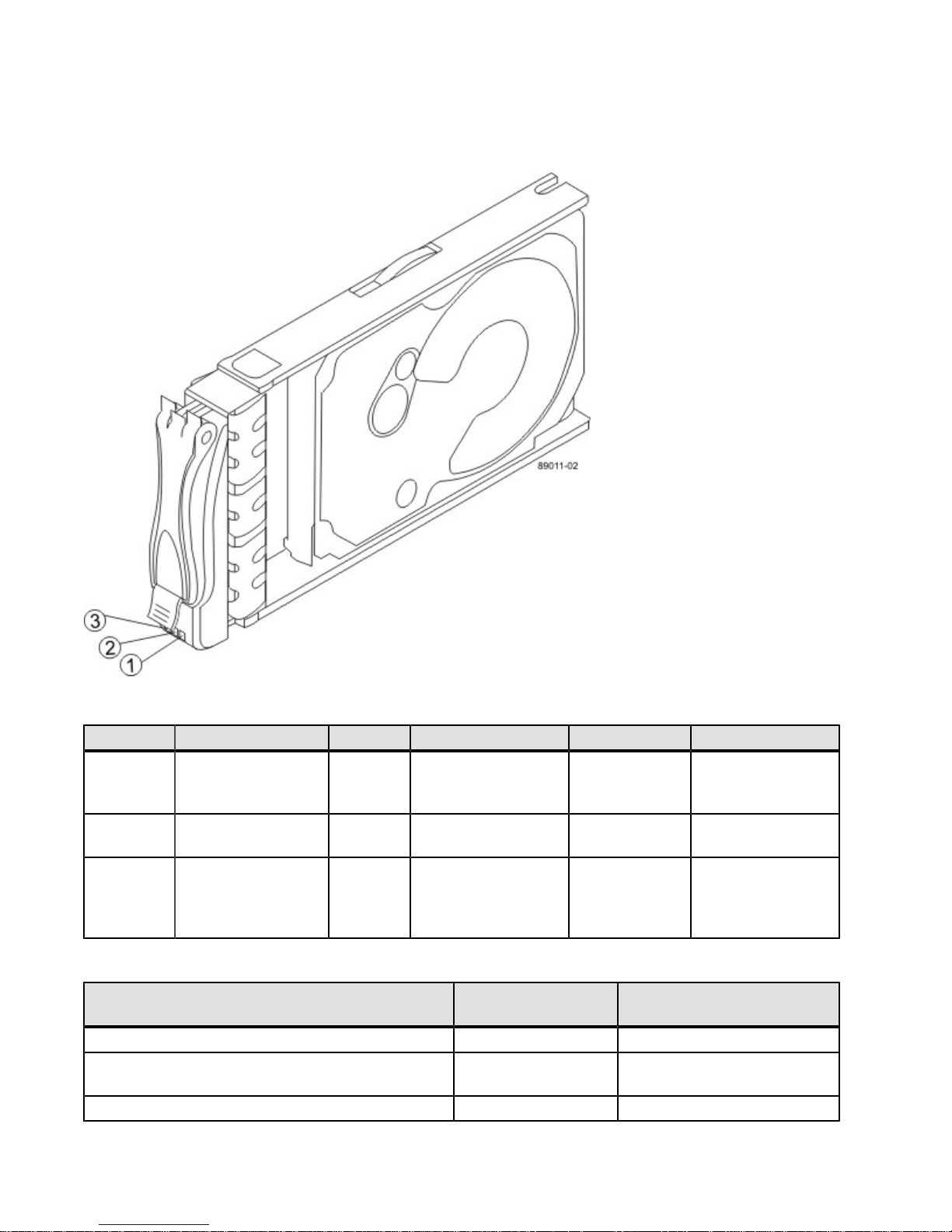
LEDs on the Drive
Figure 39. LEDs on the Drive
Table 12. LEDs on the Drive
Location LED Color On Blinking Off
1 Drive Power Green The power is turned
on, and the driveis
operating normally.
2 Drive Service Action
Required
3 Drive Service Action
Allowed
Table 13. Drive State Represented by LEDs
Drive State Drive Power LED
Power is not applied. Off Off
Normal operation –The power is turned on, but
driveI/O activity is not occurring.
Normal operation –DriveI/O activity is occurring. Blinking Off
Amber An error has
occurred.
Blue The drive canister
can be removed
safely from the flash
array.
(Green)
On Off
Drive I/O activity
is taking place.
Drive Service Action
Required LED (Amber)
The power is turned
off.
Normal status.
The drive canister
cannot be removed
safely from the flash
array.
215-08288_A0_EF550 Flash Array Installation Guide - 53
Page 58
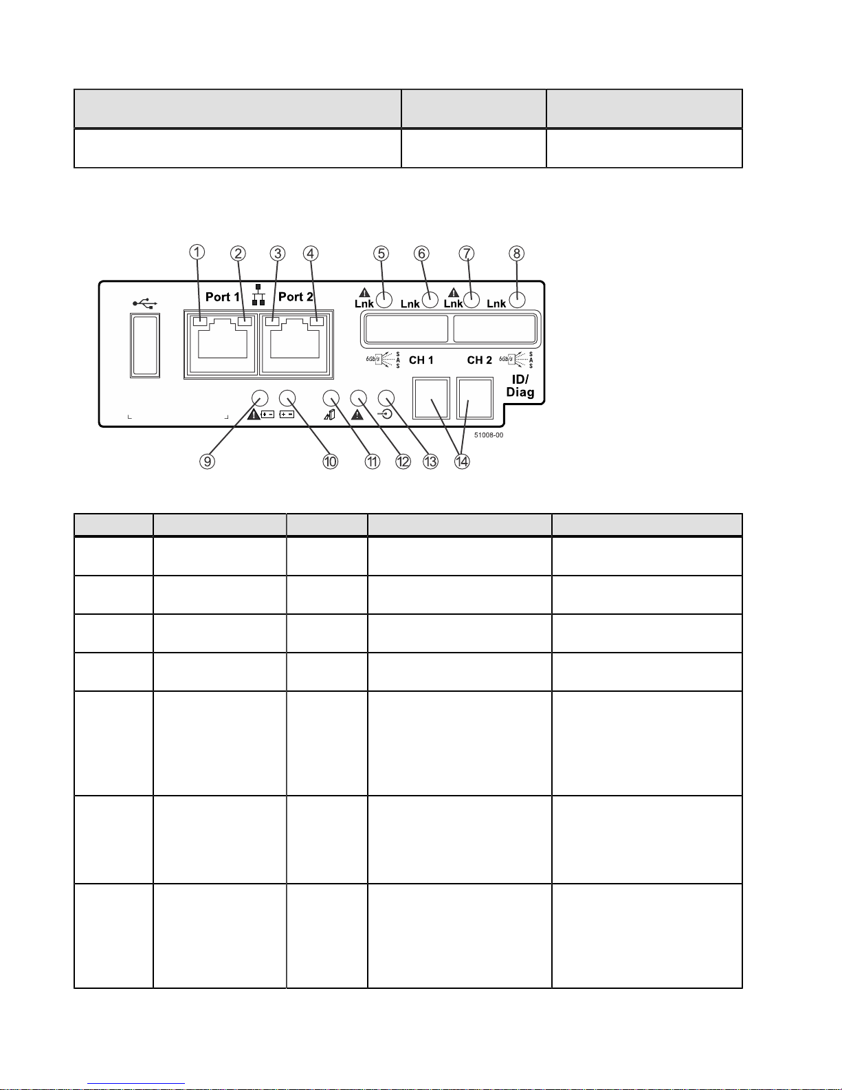
Drive State Drive Power LED
(Green)
Service action required –A fault condition exists, and
On On
the drive is offline.
LEDs on the Controller Canister Main Faceplate
Figure 40. LEDs on the Controller Canister Main Faceplate
Table 14. LEDs on the Controller Canister Main Faceplate
Drive Service Action
Required LED (Amber)
Location LED Color On Off
1 Ethernet Connector
Green There is a 1000 Gb/s rate. There is a 10BASE-T rate.
1 Link Rate LED
2 Ethernet Connector
1 Link Active LED
3 Ethernet Connector
Green The link is up (LED blinks
The link is not active.
when there is activity).
Green There is a 1000 Gb/s rate. There is a 10BASE-T rate.
2 Link Rate LED
4 Ethernet Connector
2 Link Active LED
5 Native Host Link
1 Service Action
Required LED
Green The link is up (the LED
blinks when there is activity).
Amber At least one of the four
PHYs is working, but another
PHY cannot establish the
The link is not active.
No link error has occurred.
same link to the device
connected to the Host IN
port connector.
6 Native Host Link
1 Service Action
Allowed LED
Green At least one of the four
PHYs in the Host IN port is
working and a link exists to
A link error has occurred.
the device connected to the
IN port connector.
7 Native Host Link
2 Service Action
Required LED
Amber At least one of the four
PHYs is working, but another
PHY cannot establish the
No link error has occurred.
same link to the device
connected to the Host IN
port connector.
54 - 215-08288_A0_EF550 Flash Array Installation Guide
Page 59
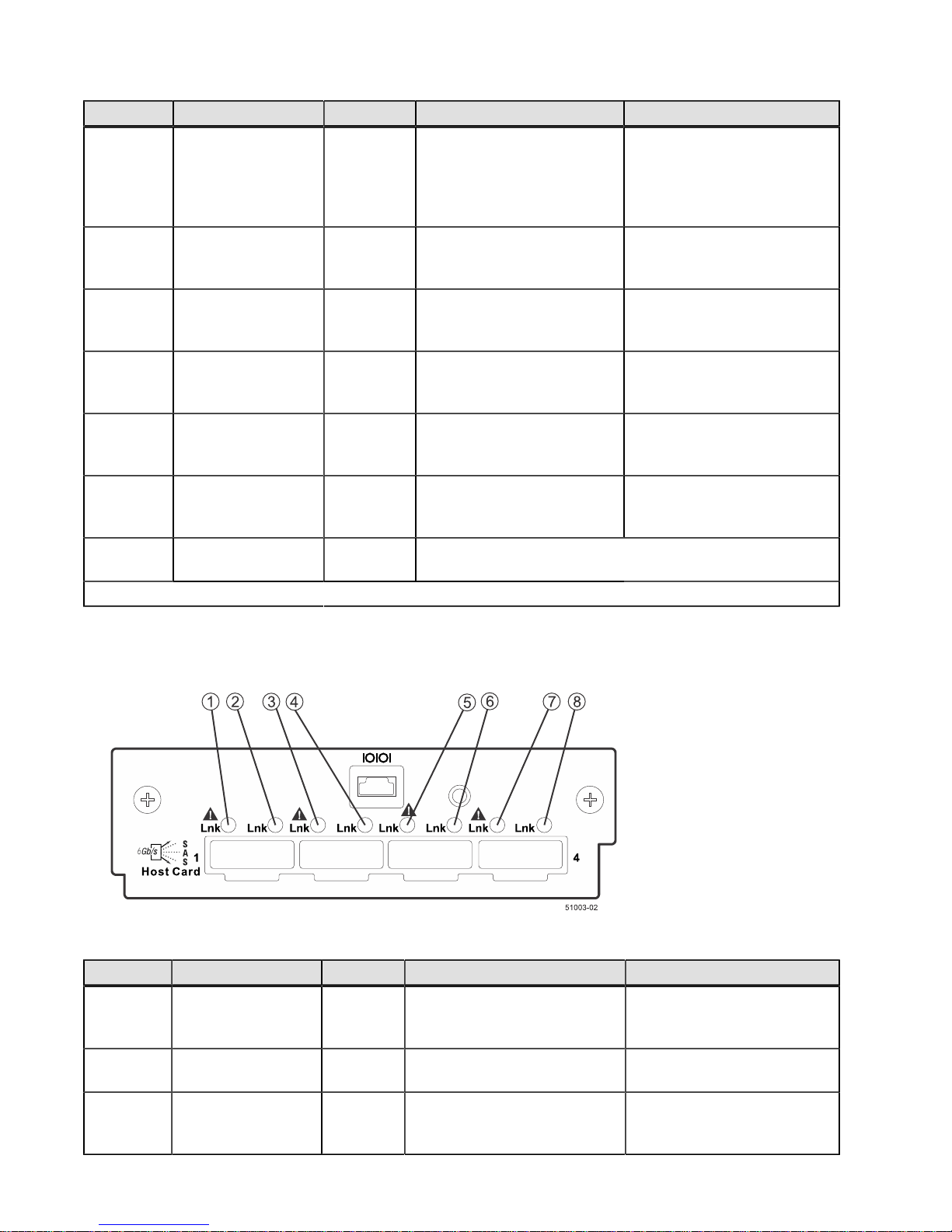
Location LED Color On Off
8 Native Host Link
2 Service Action
Allowed LED
Green At least one of the four
PHYs in the Host IN port is
working and a link exists to
A link error has occurred.
the device connected to the
IN port connector.
9 Battery Service
Action Required
Amber The battery in the controller
canister has failed.
Normal status.
LED
10 Battery Charging
LED
11 Controller Service
Action Allowed LED
12 Controller Service
Action Required
Green The battery is fully charged.
The LED blinks when the
battery is charging.
Blue The controller canister can
be removed safely from the
flash array.
Amber A fault exists within the
controllercanister.
The controller canisteris
operating without a battery or
the existing battery has failed.
The controller canister cannot
be removed safely from the
flash array.
Normal status.
LED
13 Cache Active LED Green Cache is active.* Cache is inactive or the
controller canister has been
removed from the flash array.
14 Seven Segment
Display
Green For more information refer to “Things to Know -- Seven
Segment Display Sequence Code Definitions“
* After an AC power failure, this LED blinks while cache offload is in process.
LEDs on the Controller Canister SAS Host Interface Card Subplates
Figure 41. LEDs on the Controller Canister Four-Port SAS Host Interface Card Subplates
Table 15. LEDs on the Controller Canister SAS Host Interface Card Subplates
Location LED Color On Off
1 Host Interface Card
Link 1 Fault LED
2 Host Interface Card
Link 1 Active LED
3 Host Interface Card
Link 2 Fault LED
Amber At least one link is active. The Ethernet link is down. If
both LEDs are off, a cable is
unplugged.
Green The link is up (LED blinks
The link is not active.
when there is activity).
Amber At least one link is active. The Ethernet link is down. If
both LEDs are off, a cable is
unplugged.
215-08288_A0_EF550 Flash Array Installation Guide - 55
Page 60
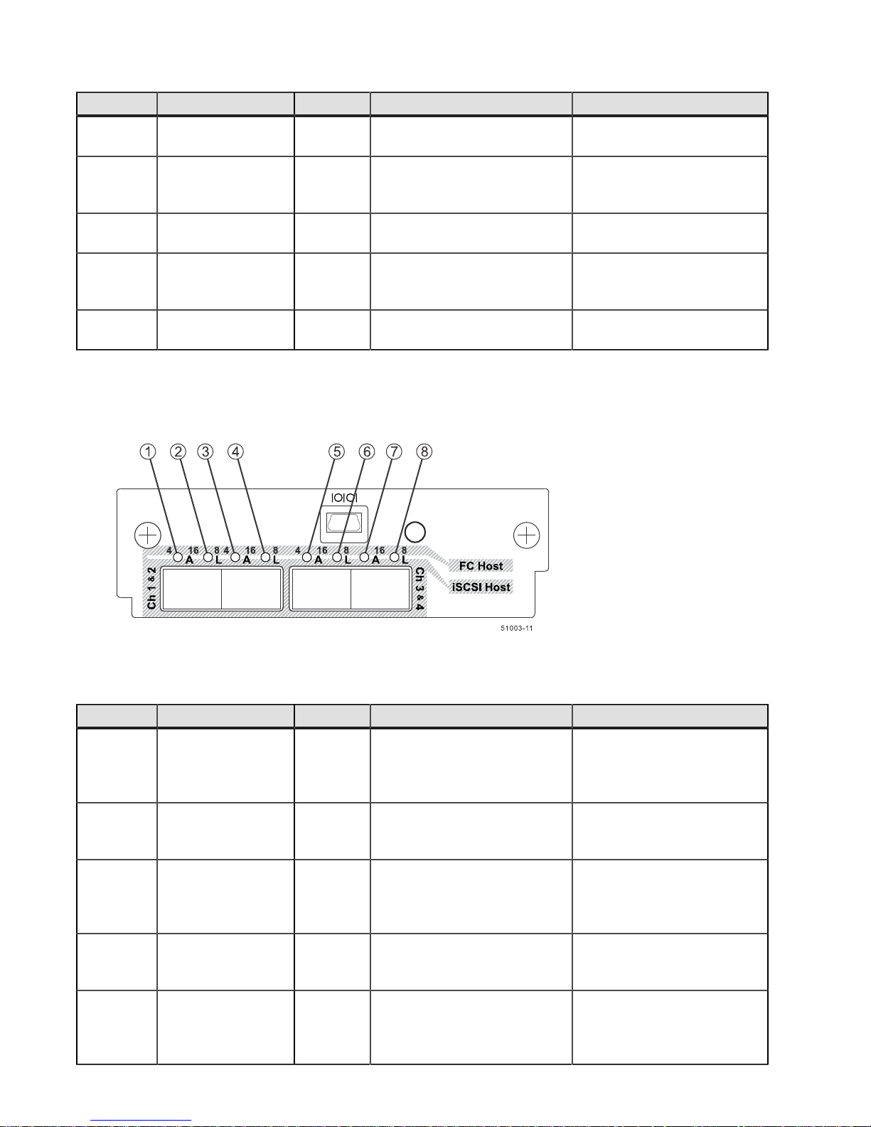
Location LED Color On Off
4 Host Interface Card
Link 2 Active LED
5 Host Interface Card
Link 3 Fault LED
Green The link is up (LED blinks
The link is not active.
when there is activity).
Amber At least one link is active. The Ethernet link is down. If
both LEDs are off, a cable is
unplugged.
6 Host Interface Card
Link 3 Active LED
7 Host Interface Card
Link 4 Fault LED
Green The link is up (LED blinks
The link is not active.
when there is activity).
Amber At least one link is active. The Ethernet link is down. If
both LEDs are off, a cable is
unplugged.
8 Host Interface Card
Link 4 Active LED
Green The link is up (LED blinks
when there is activity).
The link is not active.
LEDs on the Controller Canister FC or iSCSI Host Interface Card Subplates
Figure 42. LEDs on the Controller Canister FC or iSCSI Host Interface Card Subplate
Table 16. LEDs on the Controller Canister FC or iSCSI Host Interface Card Subplates
Location LED Color On Off
1 SFP+ Channel 1
Logical Link Up LED
Green The link is up (LED blinks
when there is activity).
The controller has not yet
loaded the driver for the
ConnectX Host Channel
Adapter.
2 SFP+ Channel 1
Green The physical link is active. The physical link is not active.
Physical Link Up
LED
3 SFP+ Channel 2
Logical Link Up LED
Green The link is up (LED blinks
when there is activity).
The controller has not yet
loaded the driver for the
ConnectX Host Channel
Adapter.
4 SFP+ Channel 2
Green The physical link is active. The link is not active.
Physical Link Up
LED
5 SFP+ Channel 3
Logical Link Up LED
Green The link is up (LED blinks
when there is activity).
The controller has not yet
loaded the driver for the
ConnectX Host Channel
Adapter.
56 - 215-08288_A0_EF550 Flash Array Installation Guide
Page 61
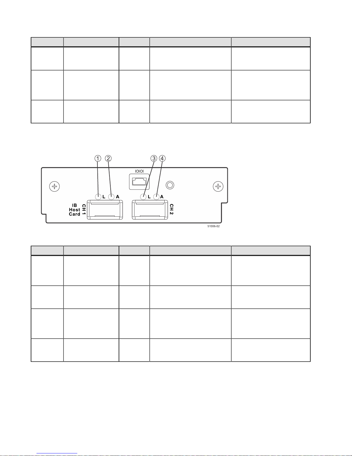
Location LED Color On Off
6 SFP+ Channel 3
Green The physical link is active. The physical link is not active.
Physical Link Up
LED
7 SFP+ Channel 4
Logical Link Up LED
Green The link is up (LED blinks
when there is activity).
The controller has not yet
loaded the driver for the
ConnectX Host Channel
Adapter.
8 SFP+ Channel 4
Green The physical link is active. The physical link is not active.
Physical Link Up
LED
LEDs on the Controller Canister Infiniband Host Interface Card Subplates
Figure 43. LEDs on the Controller Canister Infiniband Host Interface Card Subplates
Table 17. LEDs on the Controller Canister Infiniband Host Interface Card Subplates*
Location LED Color On Off
1 QSFP Channel 1
Logical Link Up LED
Amber The link is up (LED blinks
when there is activity).
The controller has not yet
loaded the driver for the
ConnectX Host Channel
Adapter.
2 QSFP Channel 1
Green The physical link is active. The physical link is not active.
Physical Link Up
LED
3 QSFP Channel 2
Logical Link Up LED
Amber The link is up (LED blinks
when there is activity).
The controller has not yet
loaded the driver for the
ConnectX Host Channel
Adapter.
4 QSFP Channel 2
Green The physical link is active. The link is not active.
Physical Link Up
LED
215-08288_A0_EF550 Flash Array Installation Guide - 57
Page 62
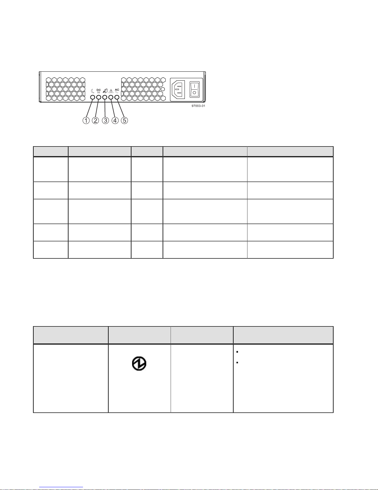
LEDs on the Power-Fan Canister
Figure 44. LEDs on the Power-Fan Canister
Table 18. LEDs on the Power-Fan Canister
Location LED Color On Off
1 Standby Power Green The flash array is in Standby
mode, and DC power is not
available.
2 Power-Fan DC
Power
3 Power-Fan Service
Action Allowed
4 Power-Fan Service
Action Required
5 Power-Fan AC Power Green AC power to the power-fan
Green DC power from the power-fan
canister is available.
Blue The power-fan canister can
be removed safely from the
flash array.
Amber A fault exists within the
power-fan canister.
canister is present.
The flash array is not in
Standby mode, and DC power
is available.
DC power from the power-fan
canister is not available.
The power-fan canister
cannot be removed safely
from the flash array.
Normal status.
AC power to the power-fan
canister is not present.
Things to Know – General Behavior of the LEDs on the Flash
Array
Table 19. LED Symbols and General Behavior
LED Symbol Location
(Canisters)
Power Power-fan
Interconnect-battery
Function
On – The controller has power.
Off – The controller does not
have power.
NOTE – The controller canisters
do not have a Power LED. They
receive their power from the power
supplies inside the power-fan
canisters.
58 - 215-08288_A0_EF550 Flash Array Installation Guide
Page 63
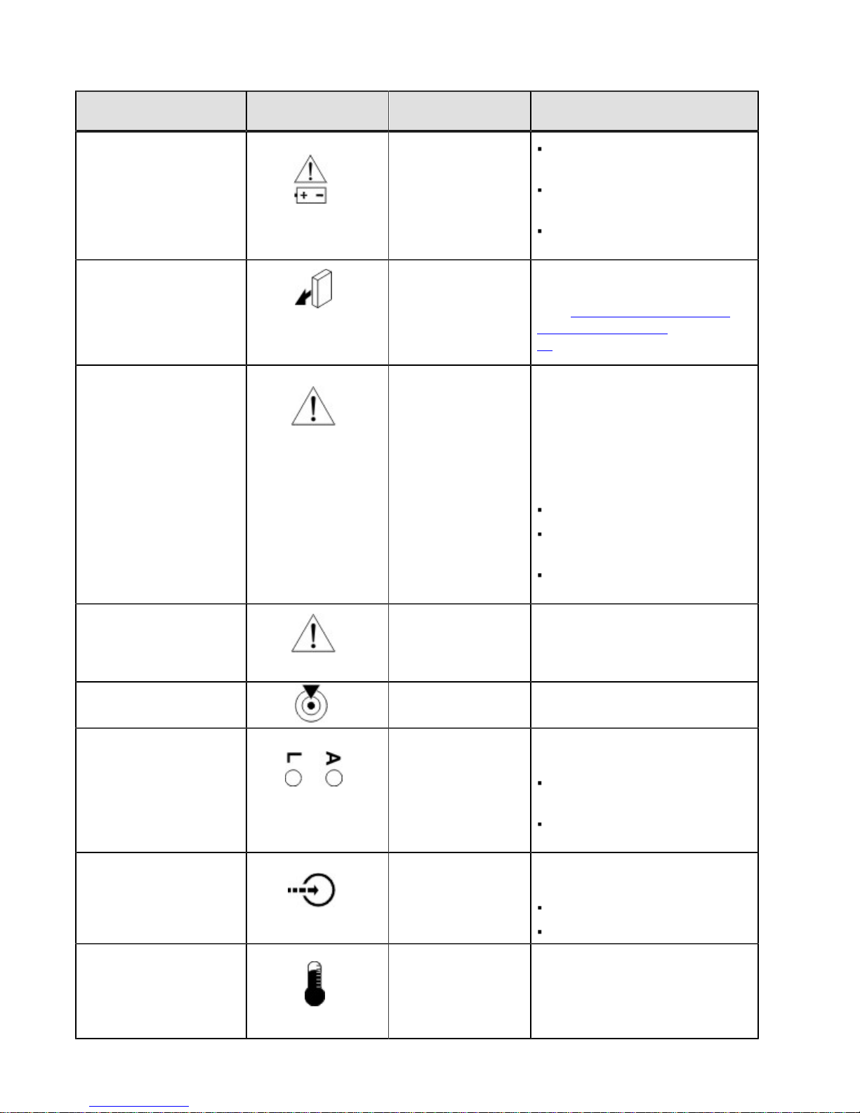
LED Symbol Location
(Canisters)
Battery Fault Battery
Function
On – The battery is missing or
has failed.
Off – The battery is operating
normally.
Blinking – The battery is
charging.
Service Action Allowed Drive (left LED, no
symbol)
Power-fan
Controller
Battery
Service Action Required
Drive On – When the drive tray LED is
(Fault)
On – You can remove the canister
safely.
See “Things to Know – Service
Action Allowed LEDs” on page
60.
on, the cable is attached and at
least one lane has a link up status,
but at least one lane has a link
down status.
Off – One of the following
conditions exists:
No cable is attached.
A cable is attached, and all
lanes have a link up status.
A cable is attached, and all
lanes have a link down status.
Service Action Required
(Fault)
Controller
Power-fan canister
On – The controller or the powerfan canister needs attention.
Off – The controller and the powerfan canister are operating normally.
Locate Front frame On – Assists in locating the tray.
Host Channel Connection
(iSCSI)
Cache Active Controller The activity of the cache is
Flash Array OverTemperature
Controller The status of the host channel is
indicated:
“L” LED on – A link is
established.
“A” LED on – Activity (data
transfer) is present.
indicated:
On – Data is in the cache.
Off – No data is in the cache.
Front bezel on the
flash array
On – The temperature of the
drive tray has reached an unsafe
condition.
Off – The temperature of the drive
tray is within operational range.
215-08288_A0_EF550 Flash Array Installation Guide - 59
Page 64
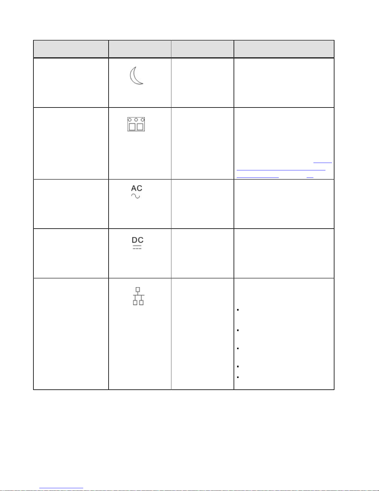
LED Symbol Location
(Canisters)
Standby Power Front bezel on the
flash array
Seven-Segment ID
Diagnostic Display
AC power Power-fan
DC power Power-fan
Ethernet Speed and
Ethernet Activity
Controller The tray ID or a diagnostic code is
NOTE – The LED
is directly above or
below the AC power
switch and the AC
power connector.
NOTE – The LED
is directly above or
below the DC power
switch and the DC
power connector.
Controller The speed of the Ethernet ports
Function
On – The controller tray is in
standby mode and the main DC
power is off.
Off – The flash array is not in
standby mode and the main DC
power is on.
indicated.
For example, if some of the cache
memory dual in-line memory
modules (DIMMs) are missing in a
controller, error code L8 appears in
the diagnostic display (see “Things
to Know – Lock-Down Codes for
the Flash Array" on page 68).
Indicates that the power supply is
receiving AC power input.
Indicates that the power supply is
receiving DC power input.
and whether a link has been
established are indicated:
Things to Know – Service Action Allowed LEDs
Each controller canister, power-fan canister, and battery canister has a Service Action Allowed LED. The Service
Action Allowed LED lets you know when you can remove a canister safely.
60 - 215-08288_A0_EF550 Flash Array Installation Guide
Left LED On –
1-Gb/s speed.
Left LED Off – 100BASE-T or
10BASE-T speed.
Right LED On – A link is
established.
Right LED Off – No link exists.
Right LED blinking – Activity is
occurring.
Page 65
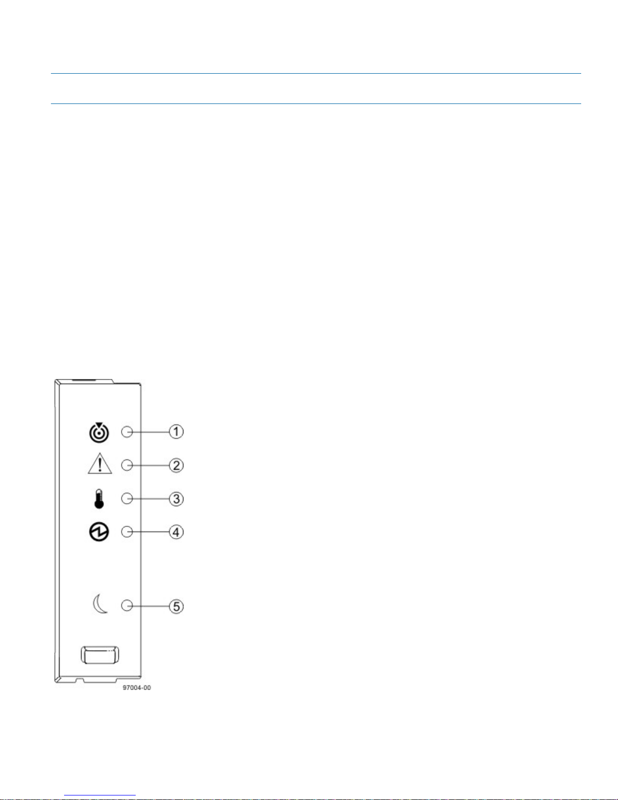
ATTENTION Possible loss of data access – Never remove a controller canister, a power-fan canister, or a battery
canister unless the appropriate Service Action Allowed LED is on.
If a controller canister or a power-fan canister fails and must be replaced, the Service Action Required (Fault) LED on
that canister comes on to indicate that service action is required. The Service Action Allowed LED also comes on if it
is safe to remove the canister. If data availability dependencies exist or other conditions that dictate a canister should
not be removed, the Service Action Allowed LED stays off.
The Service Action Allowed LED automatically comes on or goes off as conditions change. In most cases, the Service
Action Allowed LED comes on when the Service Action Required (Fault) LED comes on for a canister.
If the Service Action Required (Fault) LED comes on but the Service Action Allowed LED is off for a particular
canister, you might need to service another canister first. Check your storage management software to determine the
action that you should take.
When a service action is required for a controller canister, you must place that controller offline before removing it
from the enclosure. This prerequisite ensures that the storage array maintains accurate expansion cabling.
Things to Know – LEDs on the Drive Tray
Figure 45. LEDs on the Left End Cap
215-08288_A0_EF550 Flash Array Installation Guide - 61
Page 66
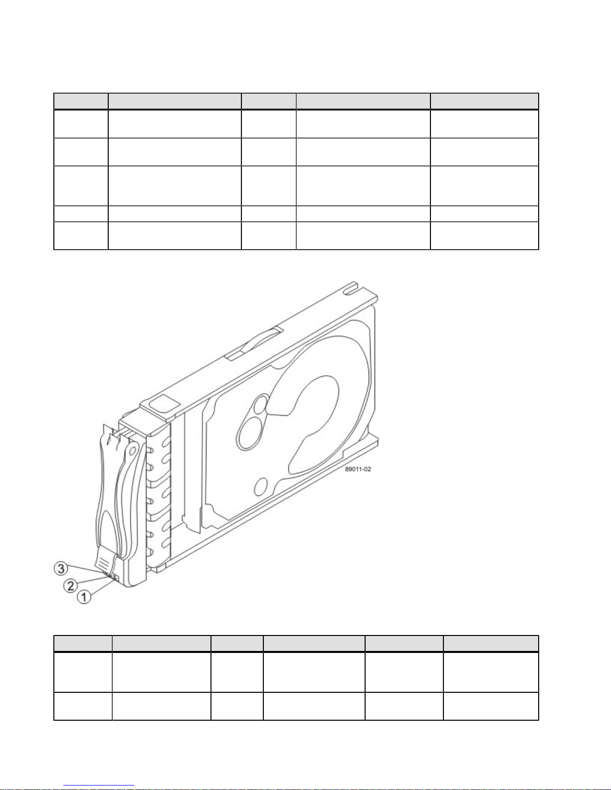
Table 20. LEDs on the Left End Cap
Location LED Color On Off
1 Drive Tray Locate White Identifies a drive tray that
Normal status.
you are trying to find.
2 Drive Tray Service Action
Required
3 Drive Tray Over-
Temperature
Amber A component within the drive
tray needs attention.
Amber The temperature of the drive
tray has reached an unsafe
Normal status.
Normal status.
level.
4 Drive Tray Power Green Power is present. Power is not present.
5 Drive Tray Standby Power Green The drive tray is in Standby
Power mode.
The drive tray is not in
Standby Power mode.
Figure 46. LEDs on the Drive
Table 21. LEDs on the Drive
Location LED Color On Blinking Off
1 Drive Power Green The power is turned
2 Drive Service Action
Required
62 - 215-08288_A0_EF550 Flash Array Installation Guide
on, and the drive is
operating normally.
Amber An error has
occurred.
Drive I/O activity
is taking place.
The power is turned
off.
Normal status.
Page 67
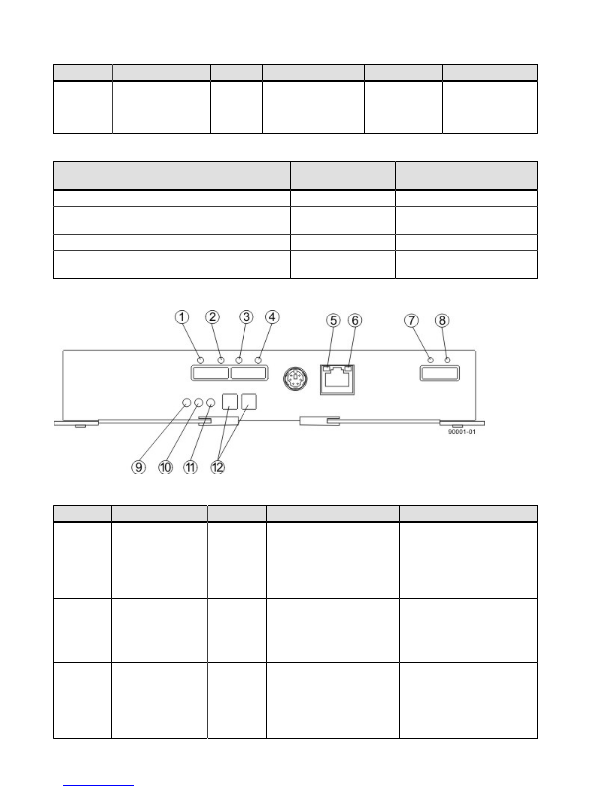
Location LED Color On Blinking Off
3 Drive Service Action
Allowed
Blue The drive canister
can be removed
safely from the drive
tray.
Table 22. Drive State Represented by LEDs
The drive canister
cannot be removed
safely from the drive
tray.
Drive State Drive Power LED
(Green)
Power is not applied. Off Off
Normal operation – The power is turned on, but
On Off
drive I/O activity is not occurring.
Normal operation – Drive I/O activity is occurring. Blinking Off
Service action required – A fault condition exists,
On On
and the drive is offline.
Figure 47. LEDs on the ESM Canister
Drive Service Action
Required LED (Amber)
Table 23. LEDs on the ESM Canister
Location LED Color On Off
1 Host Link 1 Fault Amber At least one PHY of the
2 Host Link 1 Active Green At least one of the four PHYs
3 Host Link 2 Fault Amber At least one PHY of the
No link error has occurred.
four connectors is working,
but another PHY cannot
establish the same link to the
device connected to the Host
IN port connector.
A link error has occurred.
in the In port is working, and
a link exists to the device
connected to the Host In
connector.
No link error has occurred.
four connections is working,
but another PHY cannot
establish the same link to the
device connected to the Host
In port connector.
215-08288_A0_EF550 Flash Array Installation Guide - 63
Page 68
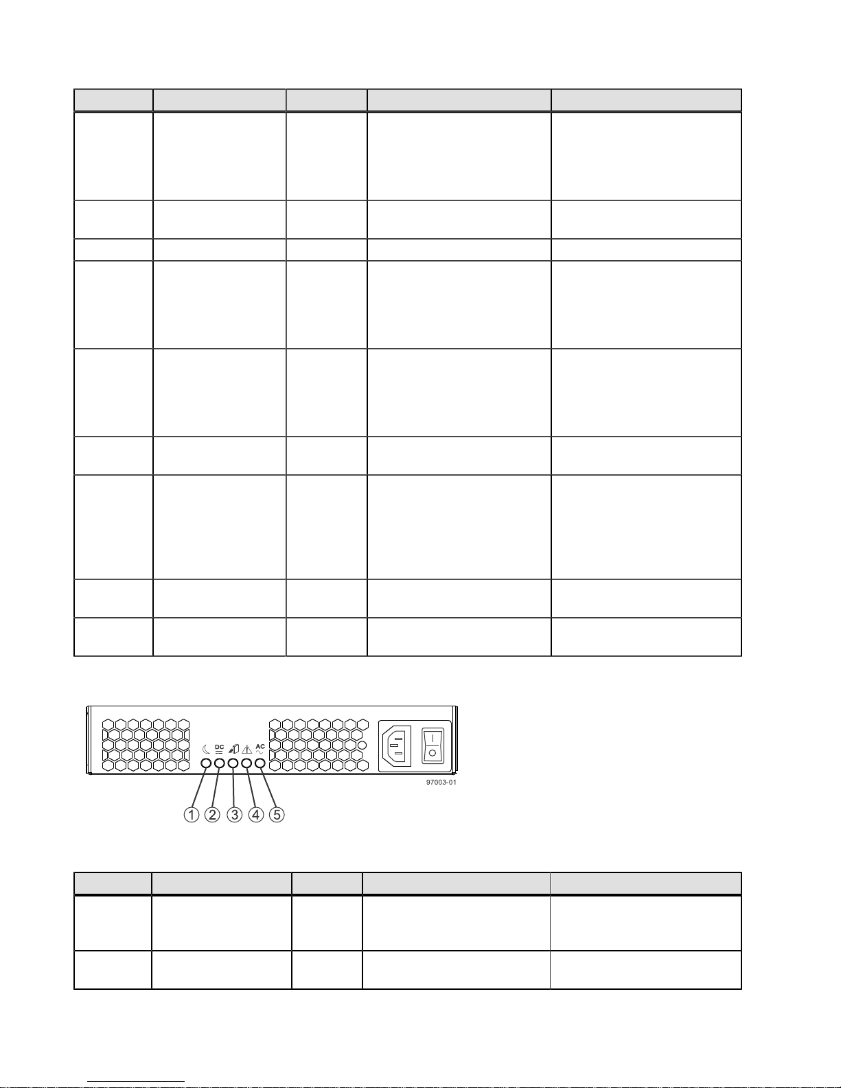
Location LED Color On Off
4 Host Link 2 Active Green At least one of the four PHYs
A link error has occurred.
in the IN port is working, and
a link exists to the device
connected to the Host In
connector.
5 Ethernet Link Active Green The link is up. (The LED
The link is not active.
blinks when there is activity.)
6 Ethernet Link Rate Green There is a 100BASE-T rate. There is a 10BASE-T rate.
7 ESM Expansion
Link Fault
Amber At least one of the four PHYs
in the Out port is working,
Normal status.
but another PHY cannot
establish the same link to the
Expansion Out connector.
8 ESM Expansion
Link Active
Green At least one of the four PHYs
in the Out port is working,
A link error has occurred.
and a link exists to the
device connected to the
Expansion Out connector.
9 ESM Service Action
Allowed
10 ESM Service Action
Required
Blue The ESM can be removed
safely from the drive tray.
Amber A fault exists within the ESM.
(This LED defaults on at
The ESM cannot be removed
safely from the drive tray.
Normal status.
power up. This LED turns
off after the software has
completed its power up selftest sequence.)
11 ESM Power Green 12V power to the ESM is
present.
12 Seven-Segment
Green See note. Not applicable.
Power is not present to the
ESM.
Tray ID
Figure 48. LEDs on the AC Power-Fan Canister
Table 24. LEDs on the Power-Fan Canister
Location LED Color On Off
1 Standby Power Green The drive tray is in Standby
2 Power-Fan DC
Power
64 - 215-08288_A0_EF550 Flash Array Installation Guide
mode, and DC power is not
available.
Green DC power from the power-fan
canister is available.
The drive tray is not in
Standby mode, and DC power
is available.
DC power from the power-fan
canister is not available.
Page 69
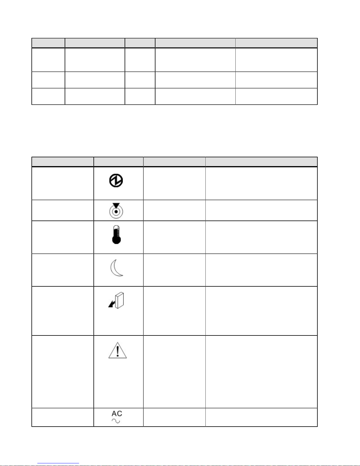
Location LED Color On Off
3 Power-Fan Service
Action Allowed
4 Power-Fan Service
Action Required
5 Power-Fan AC Power Green AC power to the power-fan
Blue The power-fan canister can
be removed safely from the
drive tray.
Amber A fault exists within the
power-fan canister.
canister is present.
The power-fan canister
cannot be removed safely
from the drive tray.
Normal status.
AC power to the power-fan
canister is not present.
General Behavior of the LEDs on the Drive Trays
Table 25. LED Symbols and General Behavior
LED Symbol Location General Behavior
Power Drive tray
ESM canister
Power-fan canister
Drive Tray Locate Front bezel on the
drive tray
On – Power is applied to the drive tray or
the canister.
Off – Power is not applied to the drive
tray or the canister.
On or blinking – Indicates the drive tray
that you are trying to find.
Drive Tray OverTemperature
Standby Power Front bezel on the
Service Action
Allowed
Service Action
Required (Fault)
AC Power ESM canister
Front bezel on the
drive tray
drive tray
ESM canister
Power-fan canister
Drive
ESM canister
Power-fan canister
Drive
Power-fan canister
On – The temperature of the drive tray
has reached an unsafe condition.
Off – The temperature of the drive tray is
within operational range.
On – The drive tray is in Standby mode,
and the main DC power is off.
Off – The drive tray is not in Standby
mode, and the main DC power is on.
On – It is safe to remove the ESM
canister, the power-fan canister, or the
drive.
Off – Do not remove the ESM canister,
the power-fan canister, or the drive.
The drive has an LED but no symbol.
On – When the drive tray LED is on, a
component within the drive tray needs
attention.
On – The ESM canister, the power-fan
canister, or the drive needs attention.
Off – The ESM canister, the power-fan
canister, and the drive are operating
normally.
The drive has an LED but no symbol.
On – AC power is present.
Off – AC power is not present.
215-08288_A0_EF550 Flash Array Installation Guide - 65
Page 70
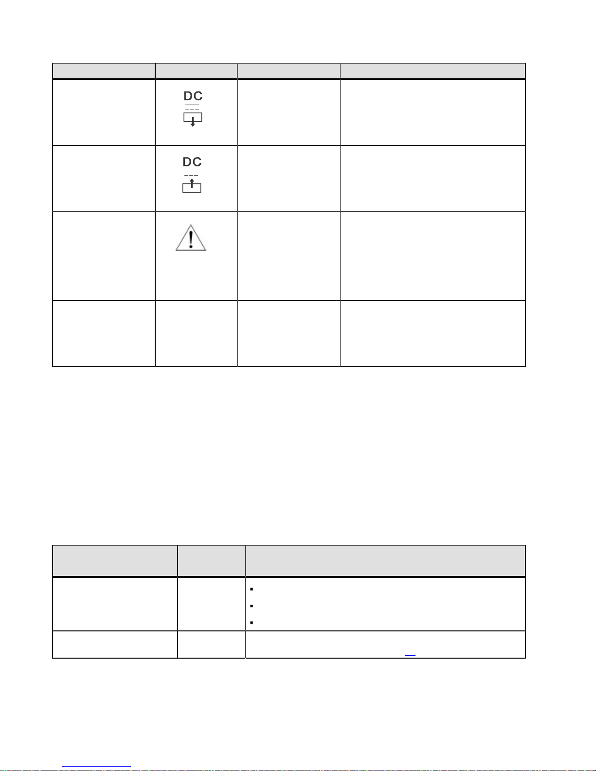
LED Symbol Location General Behavior
Output DC Power Power-fan canister On – Regulated DC output power from
the power canister and the fan canister is
present.
Off – Regulated DC output power from
the power-fan canister is not present.
Input DC Power Power-fan canister On – Regulated DC input power to the
power canister and the fan canister is
present.
Off – Regulated DC input power to the
power-fan canister is not present.
Link Service Action
Required (Fault)
Link Up Two LEDs above
each expansion
connector
ESM canister On – The cable is attached and at least
one lane has a link-up status, but one
lane has a link-down status.
Off – The cable is not attached, the cable
is attached and all lanes have a link-up
status, or the cable is attached and all
lanes have a link-down status.
ESM canister On – The cable is attached and at least
one lane has a link-up status.
Off – The cable is not attached, or the
cable is attached and all lanes have a
link-down status.
Things to Know – Seven Segment Display Sequence Code
Definitions on the EF550 Flash Array
During normal operation, the tray ID display on each controller canister shows the flash array ID. The Diagnostic LED
(lower-digit decimal point) comes on when the display is used for diagnostic codes and goes off when the display is
used to show the tray ID. The category code may be followed by a "--"+ and a "CF," followed by one of the component
location codes described in "Things to Know -- Seven-Segment Component Failure Identifications for the EF550
Flash Array" on the following page.
Table 26. Sequence Code Definitions for the EF550 Flash Array
Category Category
1
Code
Startup error
Operational error OE+ Lx+ Lock-down codes. (See "Things to Know -- Lock-Down
SE+
3
Detail Codes
88+ Power-on default
dF+ Power-on diagnostic fault
Sx Power-on validation error
Codes for the Flash Array" on page 68.)
2
66 - 215-08288_A0_EF550 Flash Array Installation Guide
Page 71
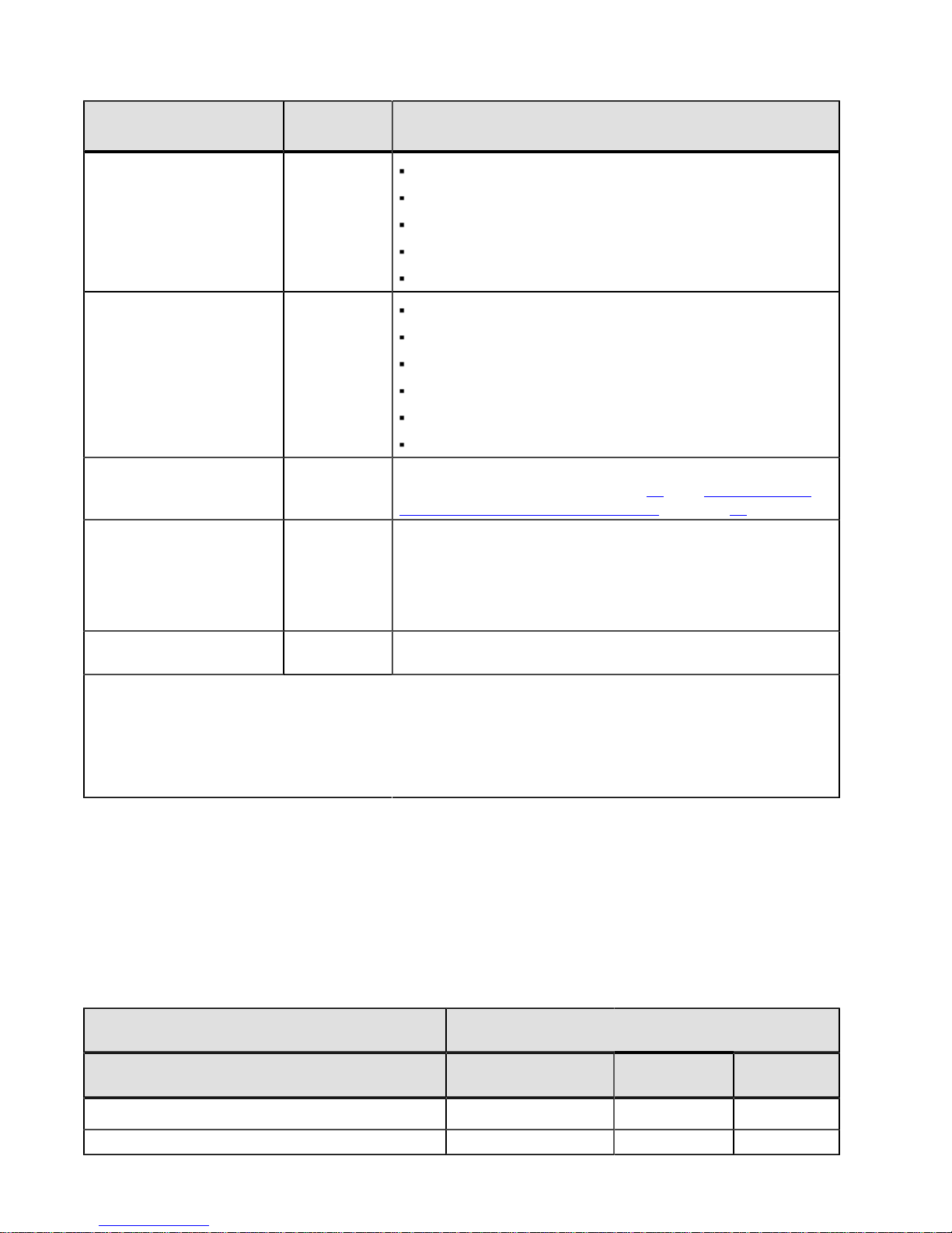
Category Category
1
Code
Detail Codes
2
Operational state OS+
Component failure CF+
Diagnostic failure dE+ Lx+ = Lock-down code.s (See "Things to Know -- Lock-Down
Category delimiter dash+
(Appears
as two short
dashes: "--").
.
End-of-sequence delimiter
Notes:
1 A two-digit code that starts a dynamic display sequence.
2 A two-digit code that follows the category code with more specific information.
3 The plus (+) sign indicates that a two-digit code displays with the Diagnostic LED on.
4 No codes display, and the Diagnostic LED is off.
blank -
4
OL+ = Offline.
bb+ = Battery backup (operating on batteries).
OH + CPU temperature exceeds the warning level
CF+ = Component failure.
Sd+ = Start of Day (SOD) processing
dx+ = Processor or cache DIMM.
Cx = Cache DIMM.
Px+ = Processor DIMM.
Hx+ = Host interface card.
Fx+ = Flash drive.
bl + Base Controller Card
Codes for the Flash Array" on page 68 and "Things to Know
– Seven-Segment Display Use Cases" on page 70.)
The separator between category-detail code pairs is used when
more than one category detail code pair exists in the sequence.
The end-of-sequence delimiter is automatically inserted by the
hardware at the end of a code sequence.
Things to Know – Seven-Segment Component Failure
Identifications for the EF550 Flash Array
Use the Seven Segment display values to identify component.
Table 27. EF550 Flash Array Failure Identifications
Component Seven-Segment Display Used in this Controller
1
Code
Processor DIMM (dx +2)
Cache DIMM (CX +) yes yes no
3
State
Power-on
Diagnostics
yes yes no
Suspended Operational
215-08288_A0_EF550 Flash Array Installation Guide - 67
Page 72
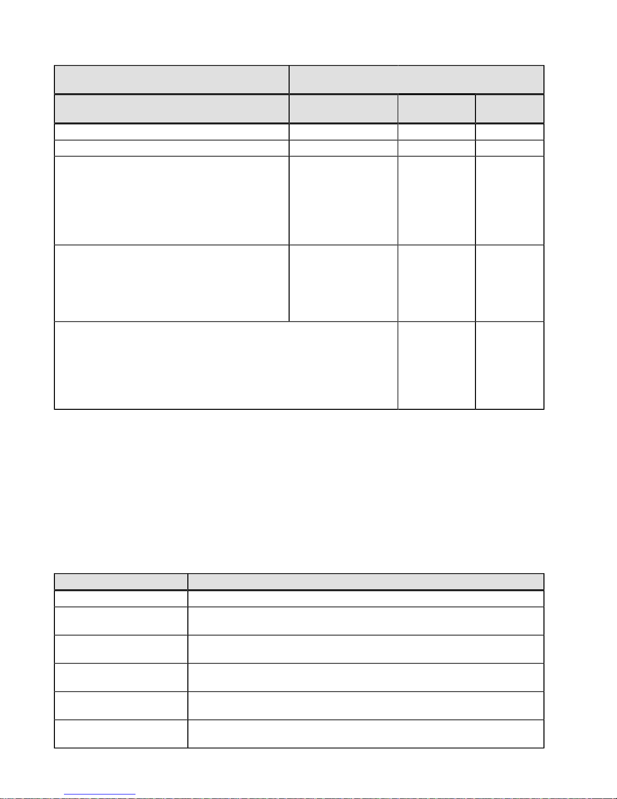
Component Seven-Segment Display Used in this Controller
State
1
Code
Host Card (HX +) yes yes yes
Flash Drive (FX +) no no yes
Category delimiter (--)
After (--), a "CF" (for Component Failure) is
displayed, followed by one of the codes specified
above.
End-of-sequence delimiter
Displays as a blank space. (No codes appear, and
the Diagnostic LED is off.)
Notes:
1 A two-digit code that starts a dynamic display sequence.
2 A two-digit code that follows the category code with more specific
information.
3 The plus (+) sign indicates that a two-digit code displays with the
Diagnostic LED on.
Power-on
Diagnostics
The separator between
category-detail
code pairs is used
when more than one
category detail code
pair exists in the
sequence.
The end-ofsequence delimiter is
automatically inserted
by the hardware at
the end of a code
sequence.
Suspended Operational
Things to Know – Lock-Down Codes for the Flash Array
Use the following table to determine the diagnostic lock-down code definitions on the Seven-Segment Display in the
controller canister. In general, these diagnostics display only when the controller is in a non-operational state. The
controller can be in a non-operation state as a result of a configuration problem (such as mismatched controller types)
or as a result of a hardware fault. If the amber Controller Service Action Required LED is on, the non-operational state
is the result of a hardware fault.
Table 28. Supported Diagnostic Lock-Down Codes on the Seven-Segment Display
Diagnostic Code Description
– – The firmware is booting.
L0 The controller types are mismatched, which result in a suspended controller
state.
L2 A persistent memory error has occurred, which results in a suspended
controller state.
L3 A persistent hardware error has occurred, which results in a suspended
controller state.
L4 A persistent data protection error has occurred, which results in a suspended
controller state.
L5 An auto-code synchronization (ACS) failure has been detected, which results
in a suspended controller state.
68 - 215-08288_A0_EF550 Flash Array Installation Guide
Page 73

Diagnostic Code Description
L6 An unsupported host interface card has been detected, which results in a
suspended controller state.
L7 A sub-model identifier either has not been set or has been mismatched, which
results in a suspended controller state.
L8 A memory configuration error has occurred, which results in a suspended
controller state.
L9 A link speed mismatch condition has been detected in either the ESM or the
power supply, which results in a suspended controller state.
Lb A host interface card configuration error has been detected, which results in a
suspended controller state.
LC A persistent cache backup configuration error has been detected, which
results in a suspended controller state.
Ld A mixed cache memory DIMMs condition has been detected, which results in
a suspended controller state.
LE Uncertified cache memory DIMM sizes have been detected, which result in a
suspended controller state.
LF The controller has locked down in a suspended state with limited symbol
support.
LH A controller firmware mismatch has been detected, which results in a
suspended controller state.
LJ The controller does not have enough memory to support the configuration,
which results in a suspended controller state.
LL The controller cannot access either midplane SBB EEPROM, which results in
a suspended controller state.
Ln A canister is not valid for a controller, which results in a suspended controller
state.
LP Drive port mapping tables are not detected, which results in a suspended
controller state.
Lr A non field replaceable unit has been replaced, which results in a suspended
controller state.
Lt A configuration data base corruption has been detected, which results in a
suspended controller state.
LU The start-of-day (SOD) reboot limit has been exceeded, which results in a
suspended controller state.
S1 The controller detects a checksum failure in EEPROM, which results in a
suspended controller state.
S2 The SBB Signature/Revision is invalid, which results in a suspended controller
state.
S3 An unsupported enclosure is detected in the storage array, which results in a
suspended controller state.
S4 The power supply is incapable of powering the controller, which results in a
suspended controller state.
S5 The SBB pairing fails, which results in a suspended controller state.
215-08288_A0_EF550 Flash Array Installation Guide - 69
Page 74
Things to Know – Seven-Segment Display Use Cases
The following table shows both startup errors and operation errors that can be used to point to a component failure.
Seven-Segment Display Uses Cases with Repeating Sequences
Use Cases Repeating Sequence
Use Case: Controller power-on
Normal power-on controller insertion
Controller inserted while held in reset
Use Cases Repeating Sequence
Use Case: Operational states
Normal operation
SE+ 88+ blank-
xy- (static controller tray ID)
Start-of-day (SOD) processing
The controller is placed in reset while showing the tray ID.
The controller is operating on batteries (cache backup).
The CPU temperature has exceeded the warning level.
Use Cases Repeating Sequence
Use Case: Component failure when the controller is
operational.
Failed host interface card
Failed flash drive
Use Cases Repeating Sequence
Use Case: Power-on diagnostic failure
A component that is not a field replaceable unit failure has
been detected.
A processor DIMM failure has been detected.
A cache memory DIMM failure has been detected.
A processor DIMM or a cache memory DIMM failure has
been detected.
OS+ Sd+ blankOS+ OL+ blankOS+ bb+ blankOS+ OH+ blank-
OS+ CF+ HX+ blankOS+ CF+ Fx+ blank-
SE+ dF+ blank-
SE+ dF+ "--"+ CF+ Px + blankSE+ dF+ "--"+ CF+ Cx + blankSE+ dF+ "--"+ CF+ dx + blank-
A host interface card failure has been detected.
An incorrect number of cache backup devices have been
detected.
Use Cases Repeating Sequence
Use Case: Controller is suspended and there are no other
errors to report.
All lockdown conditions
70 - 215-08288_A0_EF550 Flash Array Installation Guide
SE+ dF+ "--"+ CF+ Hx + blankSE+ LC+ "--"+ CF+ Fx + blank-
OH+ Lx+ blank-
Page 75
Use Cases Repeating Sequence
Use Case: The controller is suspended because of component
errors.
Persistent processor DIMM error correcting code (ECC)
errors have been detected.
OE+ L2+ "--"+ CF+ CX+ blank-
Persistent cache DIMM ECC errors have been detected.
Persistent processor or cache DIMM ECC errors have been
detected.
Use Cases Repeating Sequence
Use Case: The controller has been suspended as a result of
persistent cache backup configuration errors.
The write-protect switch is set during cache restore.
The memory size changed with dirty data in the flash drives.
Use Cases Repeating Sequence
Use Case: The controller has been suspended as a result of
diagnostic errors.
A cache memory diagnostic failure has been detected.
A base controller diagnostic failure has been detected.
A base controller IOC diagnostic failure has been detected.
OE+ L2+ "--"+ CF+ CX+ blankOE+ L2+ "--"+ CF+ CX+ blank-
OE+ LC+ blankOE+ LC+ dd+ blank-
dE+ L2+ "--"+ CF+ Cx + blankdE+ L3+ "--"+ CF+ b1 + blankdE+ L3+ "--"+ CF+ b2 + blank-
Things to Know – Seven-Segment Display for the ESMs on the
Drive Trays
During normal operation, the tray ID display on each ESM shows the drive tray ID. The Diagnostic LED (lower-digit
decimal point) comes on when the display is used for diagnostic codes and goes off when the display is used to show
the tray ID.
If a power-on or reset occurs, the Diagnostic LED, the Heartbeat LED (upper-digit decimal point), and all seven
segments of both digits come on. The Diagnostic LED remains on until the drive tray ID appears.
Table 29. Supported Diagnostic Codes on the ESM
Diagnostic Code Description
– – The firmware is booting.
.8, 8., or 88 This ESM is being held in reset by another ESM.
AA ESM A firmware is in the process of booting (the diagnostic indicator is not yet
set).
bb ESM B firmware is in the process of booting (the diagnostic indicator is not yet
set).
L0 The ESM types are mismatched.
L2 A persistent memory error has occurred.
L3 A persistent hardware error has occurred.
215-08288_A0_EF550 Flash Array Installation Guide - 71
Page 76

Diagnostic Code Description
L9 An over-temperature condition has been detected in either the ESM or the power
supply.
LL The midplane SBB VPD EEPROM cannot be accessed.
Ln The ESM canister is not valid for this drive tray.
LP Drive port mapping tables are not found.
H2 The ESM configuration is invalid or incomplete, and it operates in a Degraded
state.
H3 The maximum number of ESM reboot attempts has been exceeded.
H4 This ESM cannot communicate with the alternate ESM.
H5 A midplane harness failure has been detected in the drive tray.
H6 An ESM firmware failure has been detected.
H9 A non-catastrophic hardware failure has occurred. The ESM is operating in a
Degraded state.
J0 The ESM canister is incompatible with the drive tray firmware.
72 - 215-08288_A0_EF550 Flash Array Installation Guide
Page 77
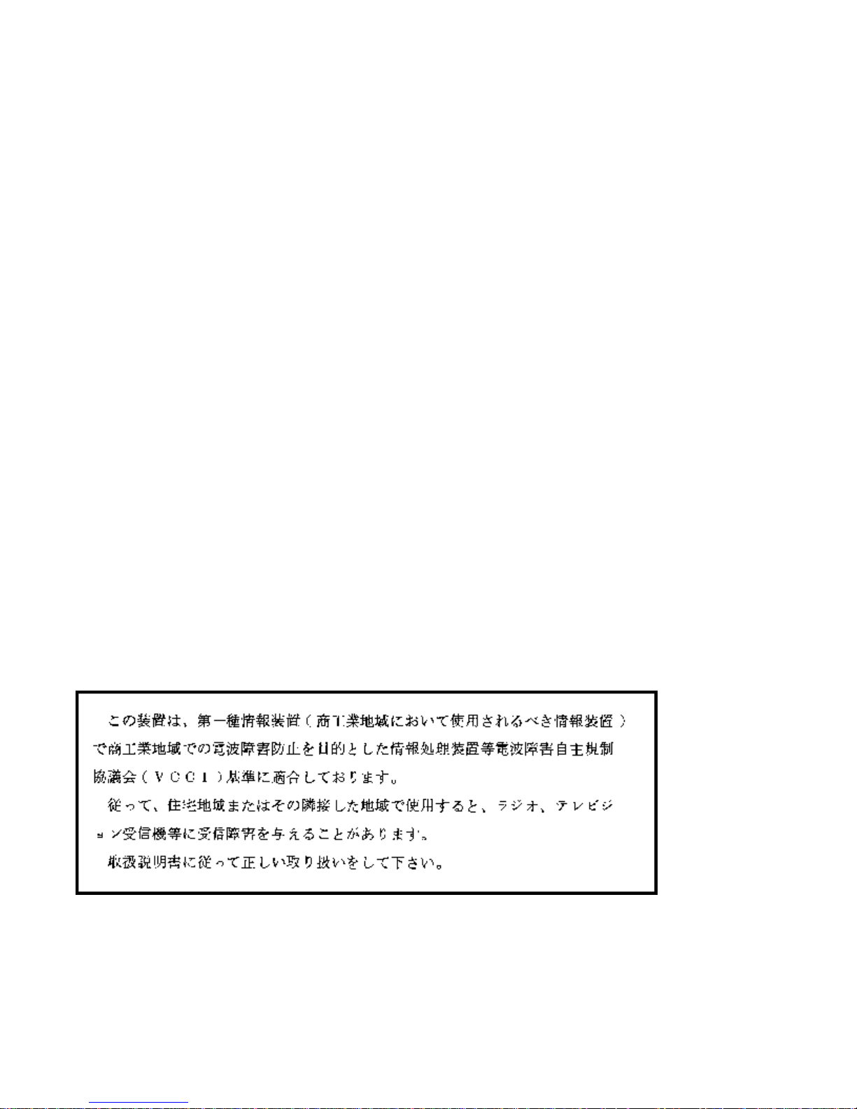
Regulatory Compliance Statements
FCC Radio Frequency Interference Statement
This equipment has been tested and found to comply with the limits for a Class A digital device, pursuant to Part 15
of the Federal Communications Commission (FCC) Rules. These limits are designed to provide reasonable protection
against harmful interference in a commercial installation. This equipment generates, uses, and can radiate radio
frequency energy and, if not installed and used in accordance with the instructions, may cause harmful interference
to radio communications. Operation of this equipment in a residential area is likely to cause harmful interference, in
which case the user will be required to correct the interference at his/her own expense.
NetApp, Inc. is not responsible for any radio or television interference caused by unauthorized modification of this
equipment or the substitution or attachment of connecting cables and equipment other than those specified by
NetApp. It is the user’s responsibility to correct interference caused by such unauthorized modification, substitution, or
attachment.
Laser Products Statement
This equipment uses Small Form-factor Pluggable (SFP) optical transceivers, which are unmodified Class 1 laser
products pursuant to 21 CFR, Subchapter J, Section 1040.10. All optical transceivers used with this product are
required to be 21 CFR certified Class 1 laser products. For outside the USA, this equipment has been tested and
found compliant with Class 1 laser product requirements contained in European Normalization standard EN 60825
1:2007. Class 1 levels of laser radiation are not considered to be hazardous and are considered safe based upon
current medical knowledge. This class includes all lasers or laser systems which cannot emit levels of optical radiation
above the exposure limits for the eye under any exposure conditions inherent in the design of the laser products.
NetApp, Inc. is not responsible for any damage or injury caused by unauthorized modification of this equipment or the
substitution or attachment of connecting cables and equipment other than those specified by NetApp. It is the user’s
responsibility to correct interference caused by such unauthorized modification, substitution, or attachment.
This Class A digital apparatus meets all requirements of the Canadian Interference-Causing Equipment Regulations.
Cet appareil numérique de la classé A respecte toutes les exigences du Règlement sure le matèriel brouilleur du
Canada.
215-08288_A0_EF550 Flash Array Installation Guide - 73
Page 78
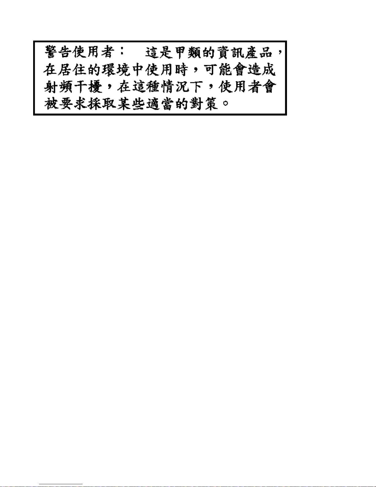
74 - 215-08288_A0_EF550 Flash Array Installation Guide
Page 79

Copyright information
Copyright © 1994–2013 NetApp, Inc. All rights reserved. Printed in the U.S.A.
No part of this document covered by copyright may be reproduced in any form or by any means— graphic, electronic,
or mechanical, including photocopying, recording, taping, or storage in an electronic retrieval system—without prior
written permission of the copyright owner.
Software derived from copyrighted NetApp material is subject to the following license and disclaimer:
THIS SOFTWARE IS PROVIDED BY NETAPP "AS IS" AND WITHOUT ANY EXPRESS OR IMPLIED
WARRANTIES, INCLUDING, BUT NOT LIMITED TO, THE IMPLIED WARRANTIES OF MERCHANTABILITY
AND FITNESS FOR A PARTICULAR PURPOSE, WHICH ARE HEREBY DISCLAIMED. IN NO EVENT SHALL
NETAPP BE LIABLE FOR ANY DIRECT, INDIRECT, INCIDENTAL, SPECIAL, EXEMPLARY, OR CONSEQUENTIAL
DAMAGES (INCLUDING, BUT NOT LIMITED TO, PROCUREMENT OF SUBSTITUTE GOODS OR SERVICES;
LOSS OF USE, DATA, OR PROFITS; OR BUSINESS INTERRUPTION) HOWEVER CAUSED AND ON ANY
THEORY OF LIABILITY, WHETHER IN CONTRACT, STRICT LIABILITY, OR TORT (INCLUDING NEGLIGENCE
OR OTHERWISE) ARISING IN ANY WAY OUT OF THE USE OF THIS SOFTWARE, EVEN IF ADVISED OF THE
POSSIBILITY OF SUCH DAMAGE.
NetApp reserves the right to change any products described herein at any time, and without notice. NetApp assumes
no responsibility or liability arising from the use of products described herein, except as expressly agreed to in writing
by NetApp. The use or purchase of this product does not convey a license under any patent rights, trademark rights,
or any other intellectual property rights of NetApp.
RESTRICTED RIGHTS LEGEND: Use, duplication, or disclosure by the government is subject to restrictions
as set forth in subparagraph (c)(1)(ii) of the Rights in Technical Data and Computer Software clause at DFARS
252.277-7103 (October 1988) and FAR 52-227-19 (June 1987).
215-08288_A0_EF550 Flash Array Installation Guide - 75
Page 80

Trademark information
NetApp, the NetApp logo, Network Appliance, the Network Appliance logo, Akorri, ApplianceWatch, ASUP,
AutoSupport, BalancePoint, BalancePoint Predictor, Bycast, Campaign Express, ComplianceClock, Cryptainer,
CryptoShred, Data ONTAP, DataFabric, DataFort, Decru, Decru DataFort, DenseStak, Engenio, Engenio logo, EStack, FAServer, FastStak, FilerView, FlexCache, FlexClone, FlexPod, FlexScale, FlexShare, FlexSuite, FlexVol,
FPolicy, GetSuccessful, gFiler, Go further, faster, Imagine Virtually Anything, Lifetime Key Management, LockVault,
Manage ONTAP, MetroCluster, MultiStore, NearStore, NetCache, NOW (NetApp on the Web), Onaro, OnCommand,
ONTAPI, OpenKey, PerformanceStak, RAID-DP, ReplicatorX, SANscreen, SANshare, SANtricity, SecureAdmin,
SecureShare, Select, Service Builder, Shadow Tape, Simplicity, Simulate ONTAP, SnapCopy, SnapDirector,
SnapDrive, SnapFilter, SnapLock, SnapManager, SnapMigrator, SnapMirror, SnapMover, SnapProtect, SnapRestore,
Snapshot, SnapSuite, SnapValidator, SnapVault, StorageGRID, StoreVault, the StoreVault logo, SyncMirror, Tech
OnTap, The evolution of storage, Topio, vFiler, VFM, Virtual File Manager, VPolicy, WAFL, Web Filer, and XBB are
trademarks or registered trademarks of NetApp, Inc. in the United States, other countries, or both.
IBM, the IBM logo, and ibm.com are trademarks or registered trademarks of International Business Machines
Corporation in the United States, other countries, or both. A complete and current list of other IBM trademarks is
available on the Web at www.ibm.com/legal/copytrade.shtml.
Apple is a registered trademark and QuickTime is a trademark of Apple, Inc. in the U.S.A. and/or other countries.
Microsoft is a registered trademark and Windows Media is a trademark of Microsoft Corporation in the U.S.A. and/
or other countries. RealAudio, RealNetworks, RealPlayer, RealSystem, RealText, and RealVideo are registered
trademarks and RealMedia, RealProxy, and SureStream are trademarks of RealNetworks, Inc. in the U.S.A. and/or
other countries.
All other brands or products are trademarks or registered trademarks of their respective holders and should be treated
as such.
NetApp, Inc. is a licensee of the CompactFlash and CF Logo trademarks.
NetApp, Inc. NetCache is certified RealSystem compatible.
76 - 215-08288_A0_EF550 Flash Array Installation Guide
Page 81

How to send your comments
You can help us to improve the quality of our documentation by sending us your feedback.
Your feedback is important in helping us to provide the most accurate and high-quality information. If you have
suggestions for improving this document, send us your comments by email to [email protected]. To help
us direct your comments to the correct division, include in the subject line the product name, version, and operating
system.
You can also contact us in the following ways:
NetApp, Inc., 495 East Java Drive, Sunnyvale, CA 94089 U.S.
Telephone: +1 (408) 822-6000
Fax: +1 (408) 822-4501
Support telephone: +1 (888) 463-8277
215-08288_A0_EF550 Flash Array Installation Guide - 77
Page 82

 Loading...