

Page 1

E-Series
E2700 Controller-Drive Tray and
Related Drive Trays Installation
Guide
November 2016 | 215-10518_B0
[email protected]
Page 2

Page 3

Contents
Deciding whether to use this guide ............................................................. 6
Step 1 - Preparing to install a controller-drive tray .................................. 7
Step 2 - Installing and configuring the switches ...................................... 29
Step 3 - Installing the host bus adapters for the controller-drive tray
Step 4 - Installing the controller-drive tray .............................................. 34
Step 5 - Connecting the controller-drive tray to the hosts ...................... 54
Table of Contents |
Key terms .................................................................................................................. 10
Storage array ................................................................................................. 10
Controller-drive tray ...................................................................................... 10
Controller ...................................................................................................... 10
Drive tray ....................................................................................................... 10
Environmental services module (ESM) ........................................................ 11
Gathering items ......................................................................................................... 11
Basic hardware .............................................................................................. 11
Configuration cables and connectors ............................................................ 12
Tools and other items .................................................................................... 14
Things to know - More details about cables and SFPs .............................................. 15
Things to know - Taking a quick glance at the hardware in a controller-drive
tray configuration ................................................................................................ 17
Things to know - Switches and routers ..................................................................... 29
Procedure - Installing and configuring switches ....................................................... 30
.................................................................................................................. 31
Key terms .................................................................................................................. 31
Host bus adapter (HBA) ................................................................................ 31
HBA host port ............................................................................................... 31
HBA host port world wide name (WWN) ..................................................... 31
Network interface card (NIC) ........................................................................ 31
Things to know - Host bus adapters and Ethernet Network Interface Cards ............ 31
Procedure - Installing host bus adapters .................................................................... 32
Things to know - General installation ....................................................................... 34
Procedure - Installing the E2712 or E2724 controller-drive tray .............................. 34
Procedure - Installing drives in the E2712 or E2724 controller-drive tray ............... 41
Procedure - Installing the E2760 controller-drive tray .............................................. 42
Procedure - Installing drives in the E2760 controller-drive tray ............................... 50
Procedure - Removing drives from a 60-drive tray ................................................... 52
Key terms .................................................................................................................. 54
Topology ........................................................................................................ 54
Direct topology .............................................................................................. 54
Switch or fabric topology .............................................................................. 54
Things to know - Storage array configuration specifications for the controller-
drive tray .............................................................................................................. 54
3
Page 4

| E2700 Controller-Drive Tray and Related Drive Trays Installation Guide
4
Things to know - Host channels ................................................................................ 55
Procedure - Connecting host cables on a controller-drive tray ................................. 58
Step 6 - Installing the drive trays for the controller-drive tray
configurations ......................................................................................... 63
Things to know - General installation of drive trays ................................................. 63
Procedure - Installing the DE1600 and DE5600 drive trays ..................................... 63
Procedure - Installing drives in the DE1600 and DE5600 drive trays ...................... 71
Procedure - Installing the DE6600 drive tray ............................................................ 72
Procedure - Installing the drives in the DE6600 drive tray ....................................... 81
Things to know - Connecting the power cords .......................................................... 83
Procedure - Connecting the power cords .................................................................. 83
Step 7 - Connecting the controller-drive tray to the drive trays ............ 84
Key terms .................................................................................................................. 84
Drive channel ................................................................................................ 84
Things to know - E2700 controller-drive tray ........................................................... 84
Things to know - Drive trays ..................................................................................... 85
Things to know - Cabling configurations .................................................................. 86
Step 8 - Connecting the Ethernet cables ................................................... 91
Key terms .................................................................................................................. 91
In-band management ..................................................................................... 91
Out-of-band management .............................................................................. 91
Things to know - Connecting Ethernet cables ........................................................... 91
Procedure - Connecting Ethernet cables ................................................................... 92
Step 9 - Connecting the power cords ........................................................ 93
Things to know - AC power cords ............................................................................. 93
Things to know - DC power cords ............................................................................ 93
Procedure - Connecting AC power cords .................................................................. 94
Procedure - Connecting DC power cords .................................................................. 95
Step 10 - Turning on the power and checking for problems in a
controller-drive tray configuration ...................................................... 97
Procedure - Turning on the power to the storage array and checking for
problems in a controller-drive tray configuration ................................................ 97
Things to know - LEDs on the controller-drive tray ................................................. 98
Things to know - LEDs on the E2760 controller-drive tray .................................... 108
Things to know - General behavior of the LEDs on the controller-drive tray ........ 111
Things to know - Service Action Allowed LEDs .................................................... 114
Things to know - LEDs on the DE1600 and DE5600 drive trays ........................... 114
Things to know - LEDs on the DE6600 drive tray .................................................. 119
Things to know - LEDs on the DE6600 drive drawers ........................................... 123
Things to know - LEDs on the DE6600 drives ....................................................... 124
Things to know - General behavior of the LEDs on the drive trays ........................ 125
Things to know - Display sequence code definitions .............................................. 127
Things to know - Component failure identifications ............................................... 128
Things to know - Lock-down codes ........................................................................ 129
Things to know - Seven-segment display use cases ................................................ 131
Page 5

Table of Contents | 5
Things to know - Seven-segment display for the ESMs on the drive trays ............. 133
Copyright information ............................................................................. 135
Trademark information ........................................................................... 136
How to send comments about documentation and receive update
notifications .......................................................................................... 137
Page 6

6
Deciding whether to use this guide
This guide is intended for hardware installers and system administrators who are installing an E2700
controller-drive tray and the related drive trays.
This guide does not provide extensive conceptual background or information about how to install and
configure the SANtricity® Storage Manager software. Refer to the appropriate SANtricity
documentation to learn how to install and configure the storage management software.
This guide is based on the following assumptions:
• You have consulted the
cabinet.
• You have all the necessary hardware required to install the controller-drive tray and drive trays for
the storage array.
Where to find the latest information about the product
You can find links to documentation and information about the latest version of the product at the
NetApp E-Series and EF-Series Systems Documentation Center
Site Preparation Guide
to plan the installation of this hardware in a
.
Page 7
Step 1 - Preparing to install a controller-drive tray
Storage arrays consist of an E2700 controller-drive tray model and can have one or more drive trays
in a cabinet.
Use this document to install one of the following E2700 controller-drive tray models and all
necessary drive trays for your configuration:
• E2712 controller-drive tray
• E2724 controller-drive tray
• E2760 controller-drive tray
The E2700 controller is available with or without a host interface card (HIC). When HICs are not
used, the host connection on the E2700 controller are through two 12-Gb/s SFF-8644 mini SAS-HD
connectors integrated into the controller circuit board. When HICs are used, the 12-Gb/s SFF-8644
mini SAS-HD connectors also can be used for host input.
The following tables show the various configuration options.
Table 1: E2712 controller-drive tray and E2724 controller-drive tray options
7
Configuration
• Simplex E2712
controller-drive tray
with no HIC
• Simplex E2724
controller-drive tray
with no HIC
Options
An E2712 controller-drive tray or E2724 controller-drive tray attached
to DE1600 drive trays, DE5600 drive trays, or DE6600 drive trays not
to exceed a maximum of 192 drive slots or 16 total trays in the storage
array. You can mix all three types of drive trays or have the following
number of drive trays in a storage array:
• 15 DE1600 drive trays with an E2712
• 14 DE1600 drive trays with an E2724
• Seven DE5600 drive trays
• Three DE6600 drive trays with an E2712 controller-drive tray
• Two DE6600 drive trays with an E2724 controller-drive tray
One 4-GB or one 8-GB DIMM memory for a maximum of 8-GB
capacity in the controller.
One 4-GB DIMM memory requires one 16-GB mSATA module for
controller cache backup. One 8-GB DIMM memory requires two 16GB mSATA modules for controller cache backup.
Page 8
8 | E2700 Controller-Drive Tray and Related Drive Trays Installation Guide
Configuration Options
• Simplex E2712
controller-drive tray
with a HIC
• Simplex E2724
controller-drive tray
with a HIC
An E2712 controller-drive tray or E2724 controller-drive tray attached
to DE1600 drive trays, DE5600 drive trays, or DE6600 drive trays not
to exceed a maximum of 192 drive slots or 16 total trays in the storage
array. You can mix three types of drive trays or have the following
number of drive trays in a storage array:
• 15 DE1600 drive trays with an E2712
• 14 DE1600 drive trays with an E2724
• Seven DE5600 drive trays
• Three DE6600 drive trays with an E2712 controller-drive tray
• Two DE6600 drive trays with an E2724 controller-drive tray
One of the following HICs in the controller:
• Two or four 12-Gb/s SFF-8644 mini SAS-HD connectors
• Two 10-Gb/s iSCSI RJ45 connectors
• Two or four 10-Gb/s iSCSI SFP connectors
• Two or four 16-Gb/s Fibre Channel SFP connectors
One 4-GB or one 8-GB DIMM memory for a maximum of 8-GB
capacity in the controller.
One 4-GB DIMM memory requires one 16-GB mSATA module for
controller cache backup. One 8-GB DIMM memory requires two 16GB mSATA modules for controller cache backup.
• Duplex E2712
controller-drive tray
with no HIC
• Duplex E2724
controller-drive tray
with no HIC
Any combination of E2700 controller-drive trays attached to DE1600
drive trays, DE5600 drive trays, or DE6600 drive trays not to exceed a
maximum of 192 drive slots or 16 total trays in the storage array. You
can mix all three types of drive trays or have the following number of
drive trays in a storage array:
• 15 DE1600 drive trays with an E2712
• 14 DE1600 drive trays with an E2724
• Seven DE5600 drive trays
• Three DE6600 drive trays with an E2712 controller-drive tray
• Two DE6600 drive trays with an E2724 controller-drive tray
One 4-GB or one 8-GB DIMM memory for a maximum of 8-GB
capacity in each controller.
One 4-GB DIMM memory requires one 16-GB mSATA module for
controller cache backup in each controller. One 8-GB DIMM memory
requires two 16-GB mSATA modules for controller cache backup in
each controller.
Page 9
Configuration Options
Step 1 - Preparing to install a controller-drive tray | 9
• Duplex E2712
controller-drive tray
with a HIC
• Duplex E2724
controller-drive tray
with a HIC
Any combination of E2700 controller-drive trays attached to DE1600
drive trays, DE5600 drive trays, or DE6600 drive trays not to exceed a
maximum of 192 drive slots or 16 total trays in the storage array. You
can mix all three types of drive trays, or have the following number of
drive trays in a storage array:
• 15 DE1600 drive trays with an E2712
• 14 DE1600 drive trays with an E2724
• Seven DE5600 drive trays
• Three DE6600 drive trays with an E2712 controller-drive tray
• Two DE6600 drive trays with an E2724 controller-drive tray
One of the following HICs (per controller):
• Two or four 12-Gb/s SFF-8644 mini SAS-HD connectors
• Two 10-Gb/s iSCSI RJ45 connectors
• Two or four 10-Gb/s iSCSI SFP connectors
• Two or four 16-Gb/s Fibre Channel SFP connectors
One 4-GB or one 8-GB DIMM memory for a maximum of 8-GB
capacity in each controller.
One 4-GB DIMM memory requires one 16-GB mSATA module for
controller cache backup in each controller. One 8-GB DIMM memory
requires two 16-GB mSATA modules for controller cache backup in
each controller.
Table 2: E2760 controller-drive tray options
Configuration
Duplex E2760
controller-drive tray
with no HIC
Options
Any combination of E2760 controller-drive trays attached to DE1600
drive trays, DE5600 drive trays, or DE6600 drive trays not to exceed a
maximum of 192 drive slots or 16 total trays in the storage array. You
can mix all three types of drive trays, or have the following number of
drive trays in a storage array:
• 11 DE1600 drive trays
• Five DE5600 drive trays
• Two DE6600 drive trays
One 4-GB or one 8-GB DIMM memory for a maximum of 8-GB
capacity in each controller.
One 4-GB DIMM memory requires one 16-GB mSATA module for
controller cache backup in each controller. One 8-GB DIMM memory
requires two 16-GB mSATA modules for controller cache backup in
each controller.
Page 10
| E2700 Controller-Drive Tray and Related Drive Trays Installation Guide
10
Configuration Options
Duplex E2760
controller-drive tray
with a HIC
Any combination of E2760 controller-drive trays attached to DE1600
drive trays, DE5600 drive trays, or DE6600 drive trays not to exceed a
maximum of 192 drive slots or 16 total trays in the storage array. You
can mix all three types of drive trays, or have the following number of
drive trays in a storage array:
• 11 DE1600 drive trays
• Five DE5600 drive trays
• Two DE6600 drive trays
One of the following HICs (per controller):
• Two or four 12-Gb/s SFF-8644 mini SAS-HD connectors
• Two 10-Gb/s iSCSI RJ45 connectors
• Two or four 10-Gb/s iSCSI SFP connectors
• Two or four 16-Gb/s Fibre Channel SFP connectors
One 4-GB or one 8-GB DIMM memory for a maximum of 8-GB
capacity in each controller.
One 4-GB DIMM memory requires one 16-GB mSATA module for
controller cache backup in each controller. One 8-GB DIMM memory
requires two 16-GB mSATA modules for controller cache backup in
each controller.
Attention: Possible hardware damage – To prevent electrostatic discharge damage to the tray,
use proper antistatic protection when handling tray components.
Key terms
Storage array
A collection of both physical components and logical components for storing data. Physical
components include drives, controllers, fans, and power supplies. Logical components include disk
pools, volume groups, and volumes. These components are managed by the storage management
software. Also known as RAID tray.
Controller-drive tray
One tray with drives, one or two controllers, fans, and power supplies. The controller-drive tray
provides the interface between a host and a storage array.
Controller
A circuit board and firmware that is located within a controller-drive tray. A controller manages the
input/output (I/O) between the host system and data volumes.
Drive tray
One tray with drives, two environmental services modules (ESMs), fans, and power supplies. A drive
tray does not contain controllers.
Page 11
Step 1 - Preparing to install a controller-drive tray | 11
Environmental services module (ESM)
A canister in the drive tray that monitors the status of the components. An ESM also serves as the
connection point to transfer data between the drive tray and the controller.
Gathering items
Before you start installing the controller-drive tray, you must have installed the cabinet in which it
will be mounted.
Use the tables in this section to verify that you have all of the necessary items to install the controllerdrive tray.
Attention: Possible hardware damage – To prevent electrostatic discharge damage to the tray,
use proper antistatic protection when handling tray components.
Basic hardware
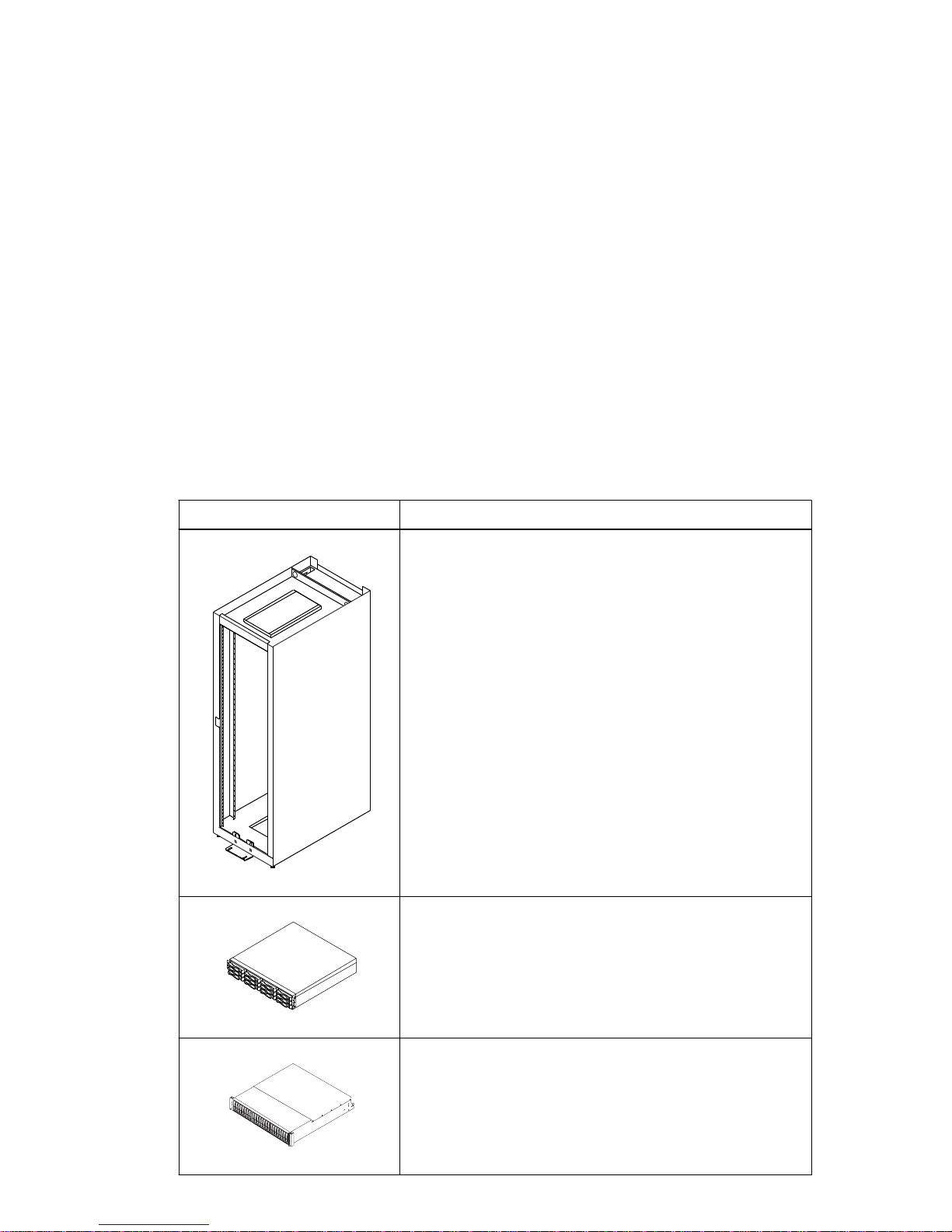
Table 3: Basic hardware
Item
Cabinet
• Ensure that your cabinet meets the installation site
specifications of the various storage array components.
Refer to the
• Depending on the power supply limitations of your cabinet,
you might need to install more than one cabinet to
accommodate the different components of the storage array.
Refer to the installation guide for your cabinet for
instructions on installing the cabinet.
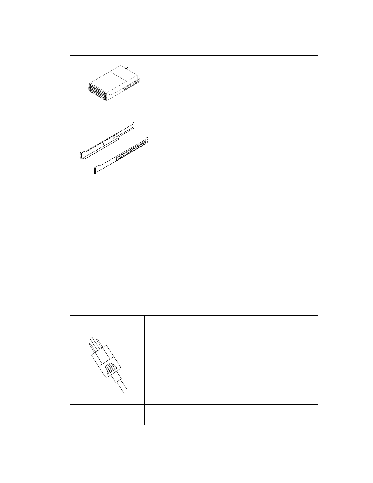
DE1600 drive tray with end caps that are packaged separately.
This drive tray ships with the drives installed and can be used
with all variations of the controller-drive tray.
Site Preparation Guide
for more information.
DE5600 drive tray with end caps that are packaged separately.
This drive tray ships with the drives installed and can be used
with all variations of the controller-drive tray.
Page 12
12 | E2700 Controller-Drive Tray and Related Drive Trays Installation Guide
Item
DE6600 drive tray (shown with the separately packaged
mounting rails attached). This drive tray can be used with all
variations of the controller-drive tray. The DE6600 drive tray
ships empty so you must install the drives when you install the
drive tray into the cabinet.
Mounting rails and screws
The mounting rails that are available with the drive tray are
designed for an industry-standard cabinet.
• SAS switch (optional)
• iSCSI switch (optional)
• Fibre Channel switch (optional)
Gigabit Ethernet switch for Management (optional)
• Host with SAS HBAs (optional)
• Host with Fibre Channel HBAs (optional)
• Host with iSCSI HBAs (optional)
Configuration cables and connectors
Table 4: Configuration cables and connectors
Item
AC power cords.
The controller-drive tray and the drive trays ship with power cords
for connecting to an external power source, such as a wall plug.
Your cabinet might have special power cords that you use instead of
the power cords that ship with the controller-drive tray and the drive
trays.
RJ-45 Ethernet cable
This cable is used for 10-Gb/s iSCSI connections.
Page 13
Step 1 - Preparing to install a controller-drive tray | 13
Item
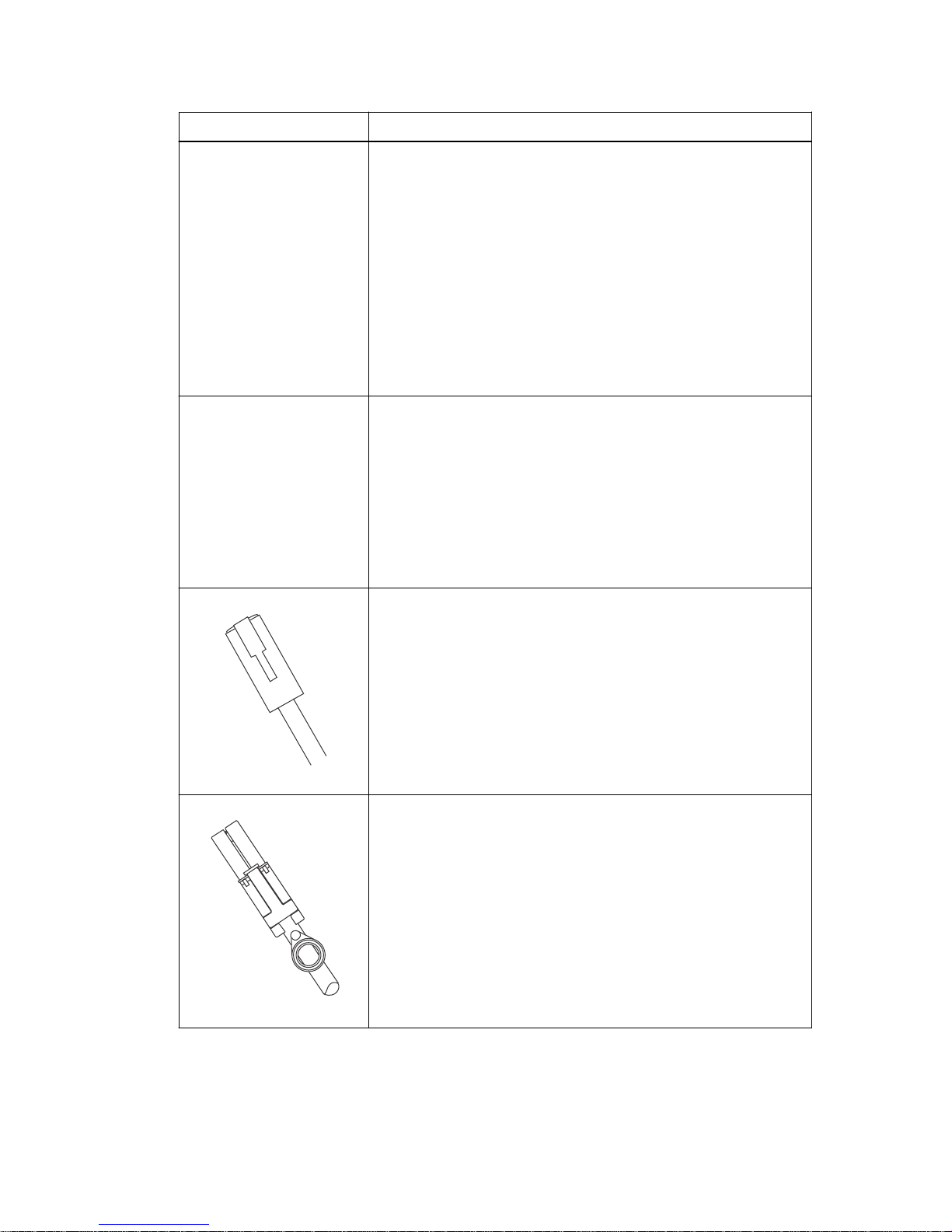
Small Form-factor Pluggable (SFP) transceivers
• SFP transceivers connect fiber-optic cables to host ports and
drive ports.
• SFP transceivers are only included with the controller-drive tray
when a fibre channel HIC is ordered or an iSCSI HIC is ordered.
• Depending on your connection requirements, you may need to
purchase SFP transceivers (two SFP transceivers for each fiberoptic cable).
• You must purchase
only
Restriction of Hazardous Substances
(RoHS)-compliant SFP transceivers.
iSCSI with SFP+ transceivers
• 2m-to-7m twin-ax passive copper cables
• Cat5 2m-to-7m RJ-45 passive cables
• 2m-to-7m RJ-45 passive cables
• 2, 3, 5, 10, or 25m OM2 cables
• 25m-to-300m OM3 cables
Ethernet cable
For information about out-of-band storage array management, see
the description for “Deciding on the management method” in the
SANtricity Storage Manager Software Installation Reference
.
SAS cables
The HD Mini-SAS (SFF-8644) to Mini-SAS (SFF-8088) SAS
cables connect each controller expansion port to the drive tray(s).
HD Mini-SAS (SFF-8644) cables for connecting to the native SAS
ports on a E2700 controller or the SAS HIC ports, to a 12-Gb/s SAS
HBA on a server.
External Mini-SAS (SFF-8088) cables for connecting between drive
tray ESMs that use a mini-SAS connection.
Page 14

14 | E2700 Controller-Drive Tray and Related Drive Trays Installation Guide
Item
Tools and other items
Table 5: Tools and other items
DB9-to-PS2 adapter cable
This cable adapts the DB9 connector on commercially available
serial cables to the PS2 connector on the ESM for drive trays in the
storage array.
This cable is used for support only. You do not need to connect it
during installation.
Serial Port cable
This 2-m cable adapts the DB9 connector on commercially available
serial cables to the mini-USB port on the controller.
This cable is used for support only. You do not need to connect it
during initial installation.
Item
Labels
Help you to identify cable connections and lets you more easily
trace cables from one tray to another
A cart
Holds the tray and components
A mechanical lift (optional)
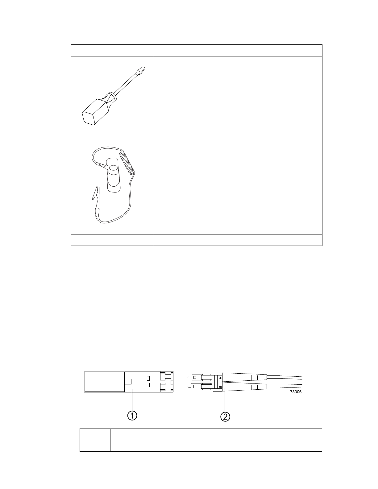
A Phillips screwdriver
Page 15
Item
Step 1 - Preparing to install a controller-drive tray |
15
A flat-blade screwdriver
Anti-static protection
A flashlight
Things to know - More details about cables and SFPs
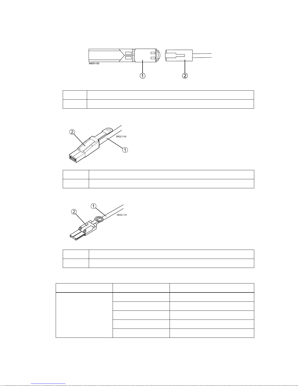
The figures in this topic display the fiber-optic cables, copper cables, SFP transceivers, SAS cables
with a SFF-8644 connection, and SAS cables with a SFF-8088 connector. The table references the
SFP transceivers that apply if you are using Fibre Channel host connections.
Note: Your SFP transceivers and cables might look slightly different from the ones shown. The
differences do not affect the performance of the SFP transceivers.
The controller-drive tray supports SAS drive connections and SAS, Fibre Channel, or iSCSI host
connections.
Warning: (W03) Risk of exposure to laser radiation – Do not disassemble or remove any part of
a Small Form-factor Pluggable (SFP) transceiver because you might be exposed to laser radiation.
• Fiber-optic cable connection
1
2 Fiber-optic cable
Active SFP transceiver
• 10-Gb/s iSCSI cable connection
Page 16
16 | E2700 Controller-Drive Tray and Related Drive Trays Installation Guide
1 Active SFP transceiver
2 Copper cable
•
SAS cable connection
1
SAS cable
2 SFF-8644 connector
• SAS cable connection
1
SAS cable
2 SFF-8088 connector
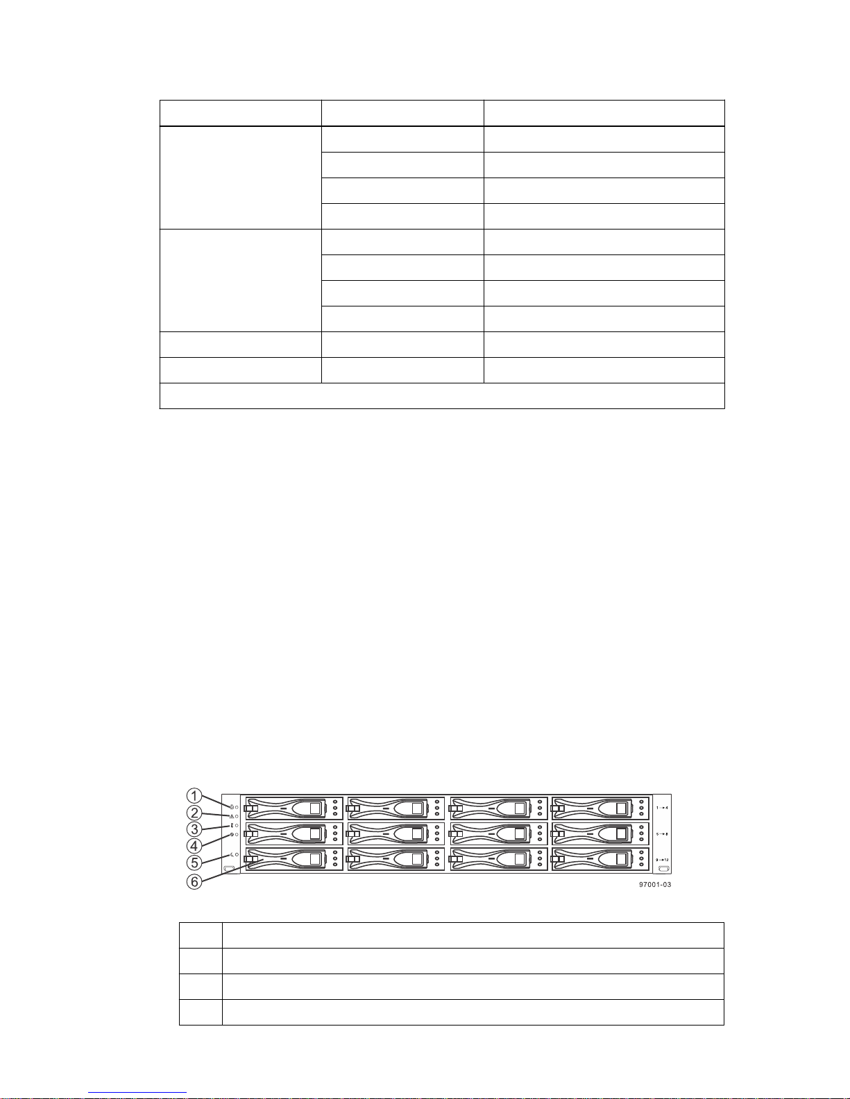
Table 6: Supported SFP transceivers*
Vendor
Model Version/Data Rate*
Avago AF57D7APZ 8 Gb/s
AFBR-57D9AMZ 8 Gb/s
AF7303SDZ 10 Gb/s
AFBR-709SMZ 10 GbE/s
AFBR-57F5UMZ-NA2 16 Gb/s or 10 GbE/s
Page 17
Step 1 - Preparing to install a controller-drive tray | 17
Vendor Model Version/Data Rate*
Finisar FTLF 8521-3 1 Gb/s
FTLF8528P2BCV-LS 8 Gb/s
FTLX8571D3BCL-LS 10 Gb/s
FTLF1429P3BNV 16 Gb/s
JDSU PLRXPL-VC-SH4-23-NA 8 Gb/s
PLRXPL-VC-SH4-23-N 8 Gb/s
PLRXPL-SC-S43-22-N 10 Gb/s
PLRXPL-SC-S43-NAe 10 GbE
Molex 74741-0005 1 Gb/s
Opnext TRS2001EN-001 10 Gb/s
*All SFP transceivers can connect and run at lower speeds, even though this is not optimal.
Things to know - Taking a quick glance at the hardware in a
controller-drive tray configuration
Each 12-drive or 24-drive tray in a storage array must have a minimum of two drives for proper
operation, while each 60 drive tray must have a minimum of 20 drives with four drives across the
front row of each drawer for proper operation.
All 60-drive trays have a limit of five solid state drives (SSDs) per drawer. If you exceed this limit for
SSDs in a particular drawer, the power source in the drawer is likely to receive too much current and
could fail.
This section provides an overview of hardware described in this document. For specific details about
how LEDs operate, see
drive tray
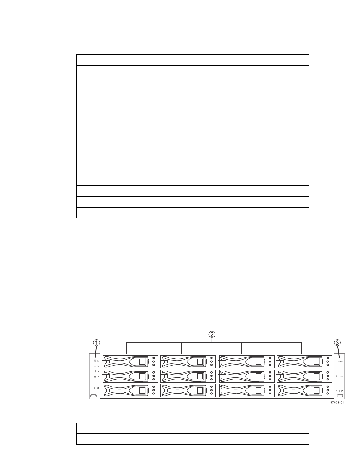
• The top of the controller-drive tray is the side with labels.
• The configuration of the host ports might appear different on your system depending on which
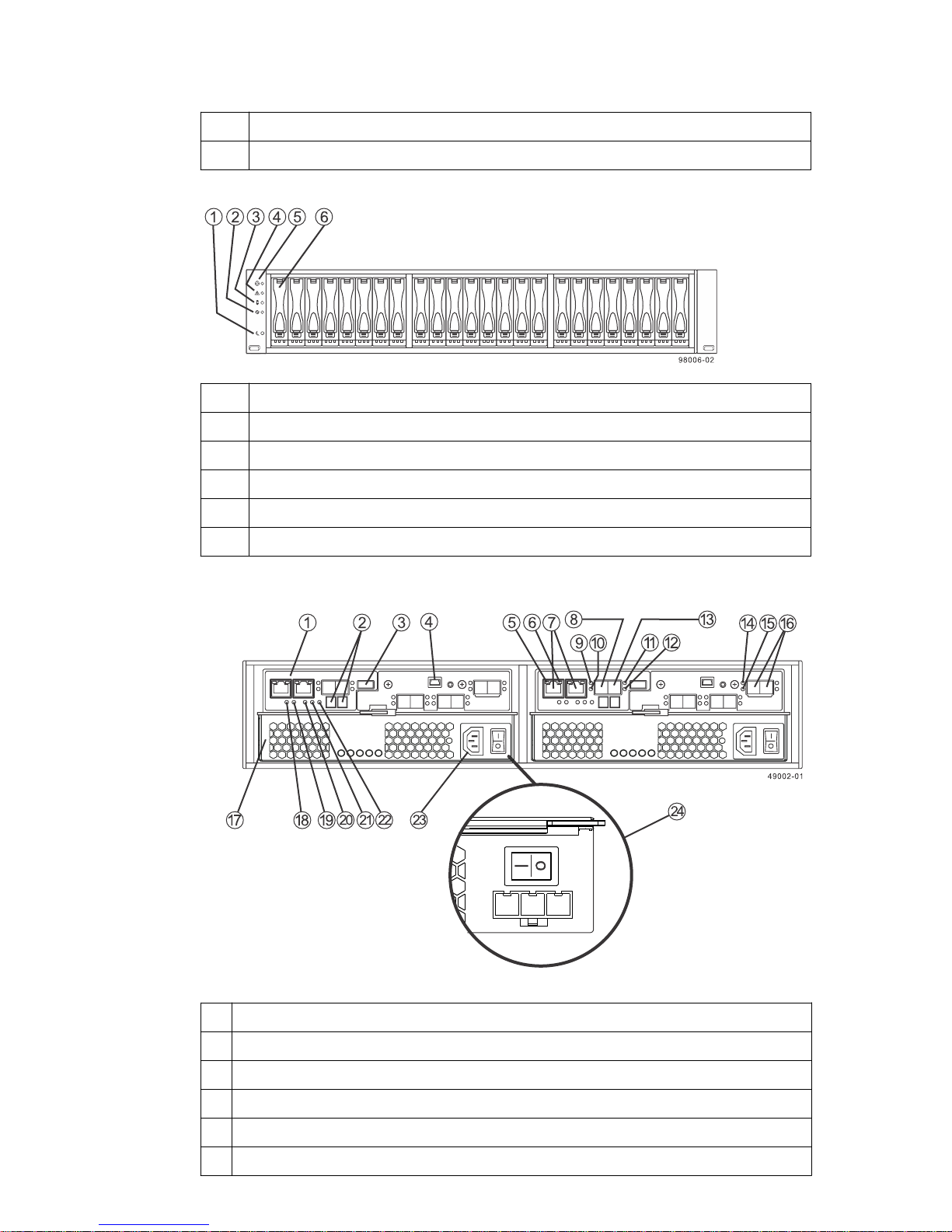
• E2712 controller-drive tray – Front view
on page 97.
host interface card configuration is installed.
Step 10 - Turning on the power and checking for problems in a controller-
1
2 End Cap Service Action Required LED
3 End Cap Over-Temperature LED
4 End Cap Power LED
End Cap Locate LED
Page 18
18 | E2700 Controller-Drive Tray and Related Drive Trays Installation Guide
5 End Cap Standby Power LED
6 Drive canister
• E2724 controller-drive tray – Front view
1 End Cap Standby Power LED
2 End Cap Power LED
3 End Cap Over-Temperature LED
4 End Cap Service Action Required LED
5 End Cap Locate LED
6 Drive canister
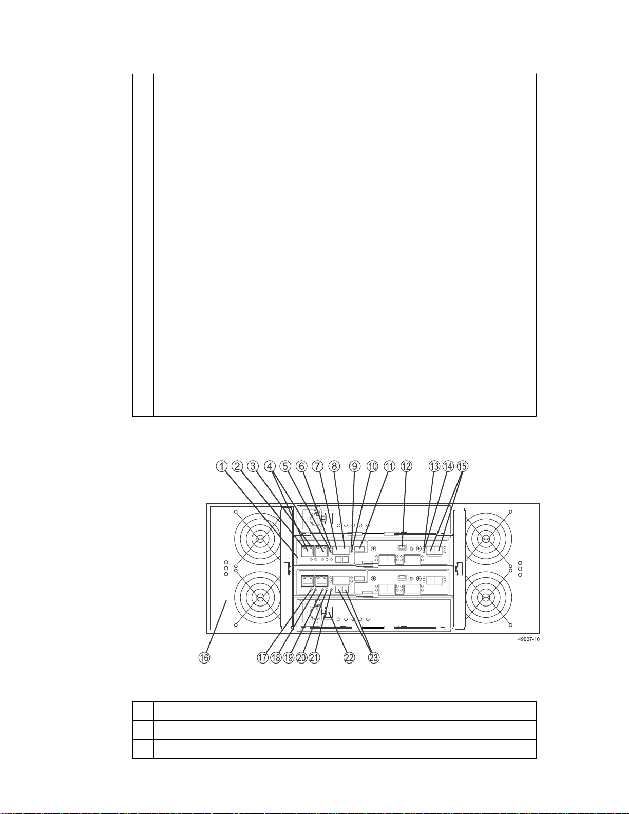
• E2712 controller-drive tray or E2724 controller-drive tray – Rear view
Controller canister
1
2 Seven-segment display
3 USB port
4 Serial port
5 1GbE Ethernet Management Port 1 Link Rate LED
6 1GbE Ethernet Management Port 2 Link Active LED
Page 19
Step 1 - Preparing to install a controller-drive tray | 19
7 1GbE Ethernet Management Port 1 and Port 2 (Port 2 is reserved for technical support)
8 SFF-8644 SAS Host Channel 1 (Ch1)
9 SAS Host 1 Link Up LED
10 SAS Host 1 Link Fault LED
11 SAS Host 2 Link Up LED
12 SAS Host 2 Link Fault LED
13 SFF-8644 SAS Host Channel 2 (Ch2)
14 SAS Expansion Link 1 Fault LED
15 SAS Expansion Link 1 Up LED
16 SFF-8644 SAS Drive Expansion Port 1 and Port 2
17 Power-fan canister
18 Battery Service Action Required LED
19 Battery Charging LED
20 Controller Service Action Allowed LED
21 Controller Service Action Required LED
22 Cache Active LED
23 AC power connector and switch
24 DC power connector and switch
• E2760 controller-drive tray – Rear view
1
Controller canister
2 1GbE Ethernet Management Port 1 Link Rate LED
3 1GbE Ethernet Management Port 2 Link Active LED
Page 20
20 | E2700 Controller-Drive Tray and Related Drive Trays Installation Guide
4 1GbE Ethernet Management Port 1 and Port 2 (Port 2 is reserved for technical support)
5 SAS Host 1 Link Up LED
6 SAS Host 1 Link Fault LED
7 SFF-8644 SAS Host Channel 1
8 SFF-8644 SAS Host Channel 2
9 SAS Host 2 Link Fault LED
10 SAS Host 2 Link Up LED
11 USB port
12 Serial port
13 SAS Expansion Link 1 Fault LED
14 SAS Expansion Link 1 Up LED
15 SFF-8644 SAS Drive Expansion Port 1 and Port 2
16 Fan canister
17 Battery Service Action Required LED
18 Battery Charging LED
19 Controller Service Action Allowed LED
20 Controller Service Action Required LED
21 Cache Active LED
22 Power canister switch
23 Seven-segment display
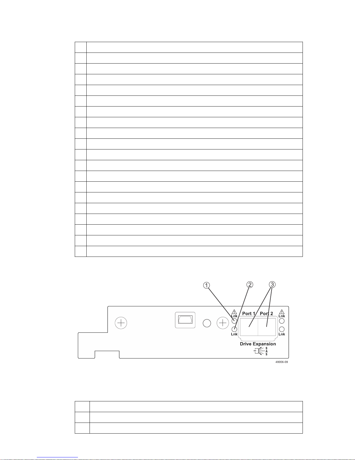
• Right rear subplate with no host interface card (HIC)
1
SAS Expansion Link 1 Up LED
2 SAS Expansion Link 1 Fault LED
3 SFF-8644 SAS Drive Expansion Port 1 and Port 2
Page 21
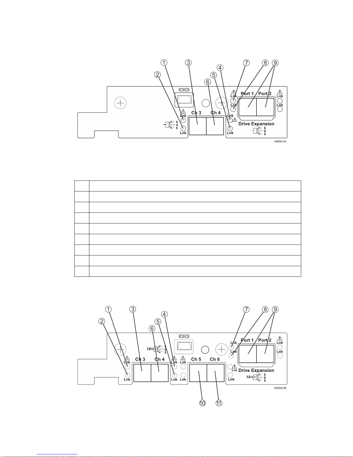
Step 1 - Preparing to install a controller-drive tray |
• Right-rear subplate with a two-port 12 Gb/s SAS HIC
1 Host Interface Card Channel 3 Fault LED
21
2 Host Interface Card Channel 3 Link Up LED
3 SFF-8644 SAS Host Interface Card Channel 3
4 Host Interface Card Channel 4 Fault LED
5 Host Interface Card Channel 4 Link Up LED
6 SFF-8644 SAS Host Interface Card Channel 4
7 SAS Expansion Port 1 Fault LED
8 SAS Expansion Port 1 Link Up LED
9 SFF-8644 SAS Drive Expansion Port 1 and Port 2
• Right-rear subplate with a four-port 12 Gb/s SAS HIC
Page 22
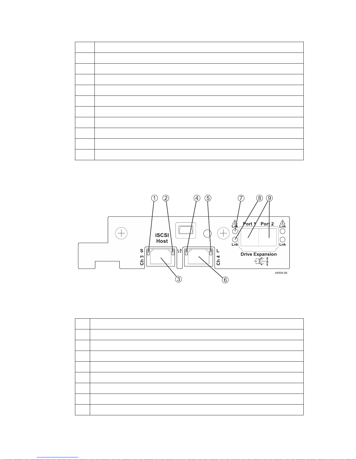
| E2700 Controller-Drive Tray and Related Drive Trays Installation Guide
22
1 Host Interface Card Channel 3 Fault LED
2 Host Interface Card Channel 3 Link Up LED
3 SFF-8644 SAS Host Interface Card Channel 3
4 Host Interface Card Channel 4 Fault LED
5 Host Interface Card Channel 4 Link Up LED
6 SFF-8644 SAS Host Interface Card Channel 4
7 SAS Expansion Port 1 Fault LED
8 SAS Expansion Port 1 Link Up LED
9 SFF-8644 SAS Drive Expansion Port 1 and Port 2
10 SFF-8644 SAS Host Interface Card Channel 5
11 SFF-8644 SAS Host Interface Card Channel 6
•
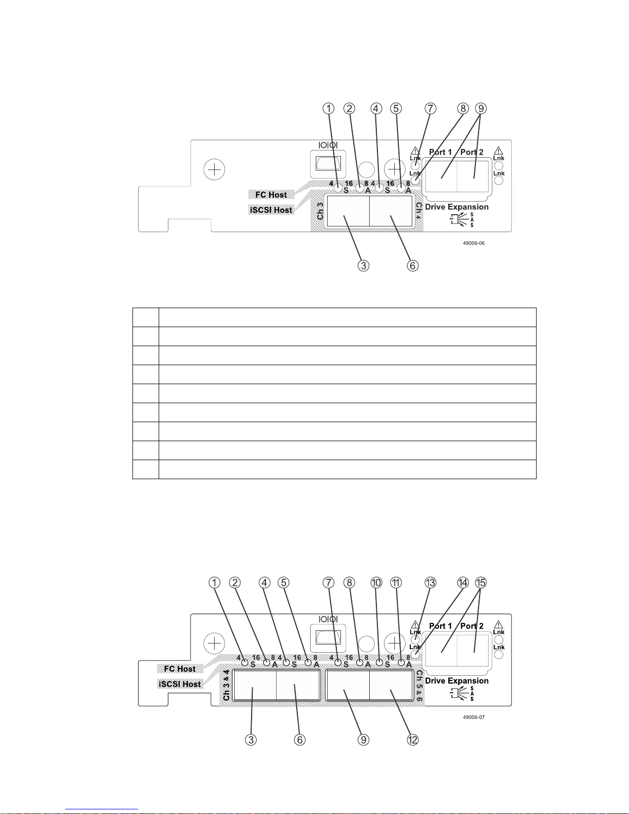
Right-rear subplate with a two-port 1 Gb/s or 10 Gb/s iSCSI HIC
1
Host Interface Card Channel 3 Fault LED
2 Host Interface Card Channel 3 Link Up LED
3 iSCSI Host Interface Card Channel 3
4 iSCSI Host Interface Card Channel 4 Fault LED
5 Host Interface Card Channel 4 Link Up LED
6 iSCSI Host Interface Card Channel 4
7 SAS Expansion Port 1 Fault LED
8 SAS Expansion Port 1 Link Up LED
9 SFF-8644 SAS Drive Expansion Port 1 and Port 2
• Right-rear subplate with a two-port 16 Gb/s Fibre Channel HIC
Page 23
Step 1 - Preparing to install a controller-drive tray |
1 FC Channel 3 - 4-Gb Link Rate LED*
2 FC Channel 3 - 8-Gb Link Rate LED*
23
3 FC Host Interface Card Channel 3
4 FC Channel 4 - 4-Gb Link Rate LED*
5 FC Channel 4 - 8-Gb Link Rate LED*
6 FC Host Interface Card Channel 4
7 SAS Expansion Port 1 Fault LED
8 SAS Expansion Port 1 Link Up LED
9 SFF-8644 SAS Drive Expansion Port 1 and Port 2
* When both LEDs for a channel are on, the link rate is 16 Gb. The “A” and “L” labels refer to
Activity and Link, respectively, when an iSCSI HIC is used.
• Right-rear subplate with a four-port 16 Gb/s Fibre Channel HIC
Page 24
24 | E2700 Controller-Drive Tray and Related Drive Trays Installation Guide
1 FC Channel 3 - 4-Gb Link Rate LED*
2 FC Channel 3 - 8-Gb Link Rate LED*
3 FC Host Interface Card Channel 3
4 FC Channel 4 - 4-Gb Link Rate LED*
5 FC Channel 4 - 8-Gb Link Rate LED*
6 FC Host Interface Card Channel 4
7 FC Channel 5 - 4-Gb Link Rate LED*
8 FC Channel 5 - 8-Gb Link Rate LED*
9 FC Host Interface Card Channel 5
10 FC Channel 6 - 4-Gb Link Rate LED*
11 FC Channel 6 - 8-Gb Link Rate LED*
12 FC Host Interface Card Channel 6
13 SAS Expansion Port 1 Fault LED
14 SAS Expansion Port 1 Link Up LED
15 SFF-8644 SAS Drive Expansion Port 1 and Port 2
* When both LEDs for a channel are on, the link rate is 16 Gb. The “A” and “L” labels refer to
Activity and Link, respectively, when an iSCSI HIC is used.
Drive trays
Attention: Possible equipment damage – You must use the supported drives in the drive tray to
ensure proper operation. For information about supported drives, contact technical support.
Attention: Risk of equipment malfunction –To avoid exceeding the functional and
environmental limits, install only drives that have been provided or approved by NetApp, Inc. Not
all controller-drive trays are shipped with pre-populated drives. System integrators, resellers,
system administrators, or users of the controller-drive tray can install the drives.
• DE1600 drive tray – Front view
1
Left end cap (has the drive tray LEDs)
2 Drives
Page 25
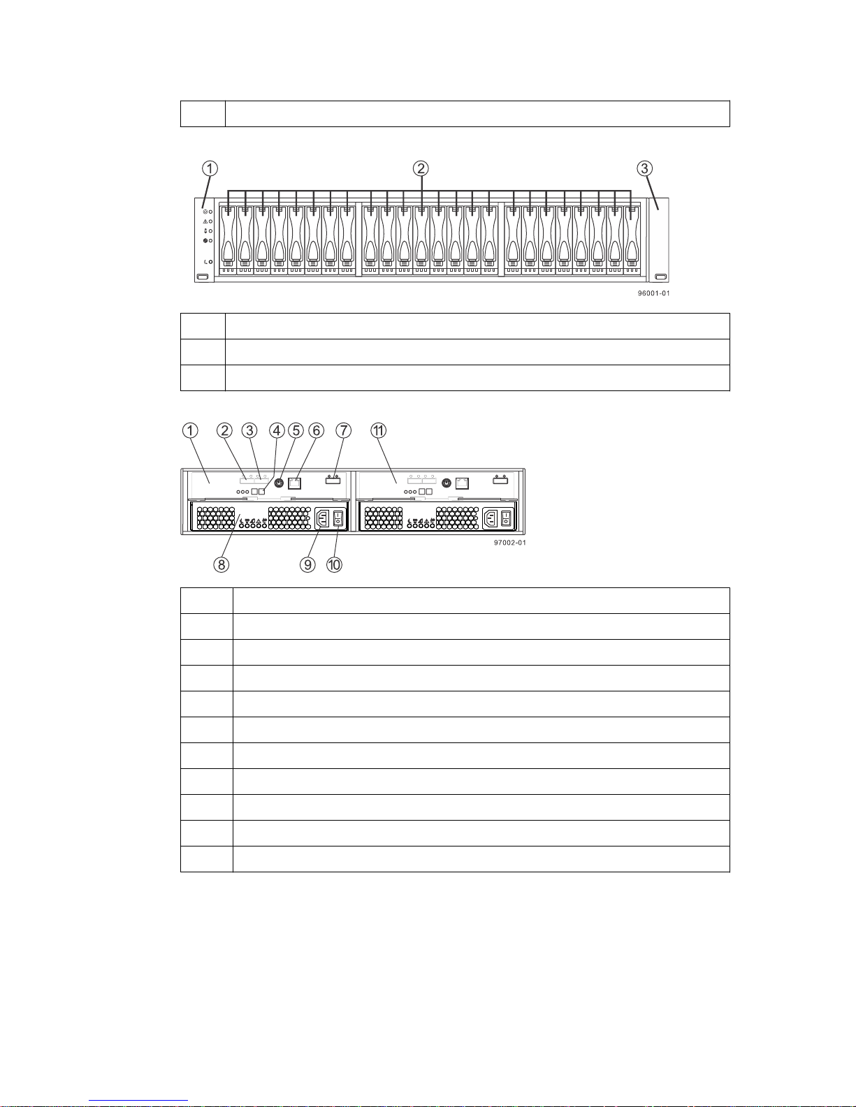
Step 1 - Preparing to install a controller-drive tray |
3 Right end cap
• DE5600 drive tray – Front view
1 Left end cap (has the drive tray LEDs)
2 Drives
3 Right end cap
•
DE1600 or DE5600 drive tray with AC power option – Rear view
25
1
ESM A canister
2 Expansion port SFF-8088 connector 1 (IN)
3 Expansion port SFF-8088 connector 2 (IN)
4 Seven-segment display
5 Serial port
6 Ethernet connector
7 Expansion port SFF-8088 connector (OUT)
8 Power-fan canister
9 Power connector
10 Power switch
11 ESM B canister
• DE1600 or DE5600 drive tray with DC power option – Rear view
Page 26
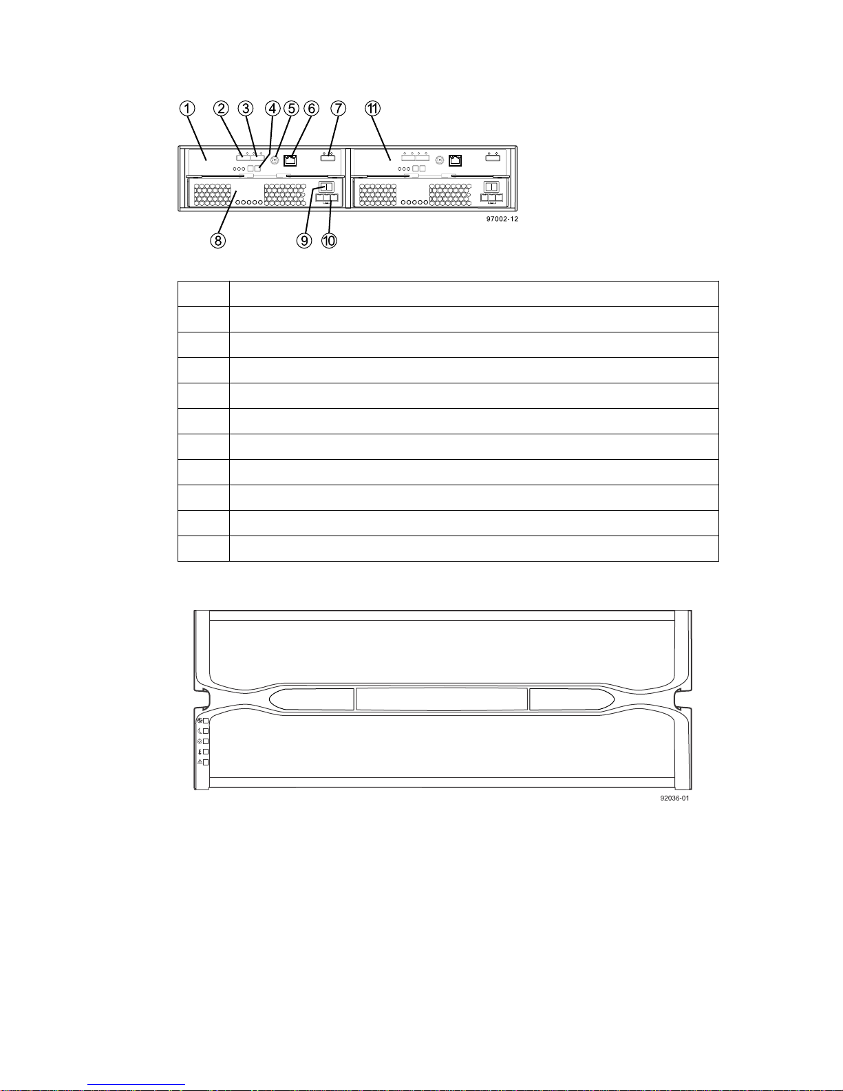
26 | E2700 Controller-Drive Tray and Related Drive Trays Installation Guide
1 ESM A canister
2 Expansion port SFF-8088 connector 1 (IN)
3 Expansion port SFF-8088 connector 2 (IN)
4 Seven-segment display
5 Serial port
6 Ethernet connector
7 Expansion port SFF-8088 connector (OUT)
8 Power-fan canister
9 Power connector
10 Power switch
11 ESM B canister
• DE6600 drive tray – Front view with bezel
• DE6600 drive tray – Front view with bezel removed
Page 27
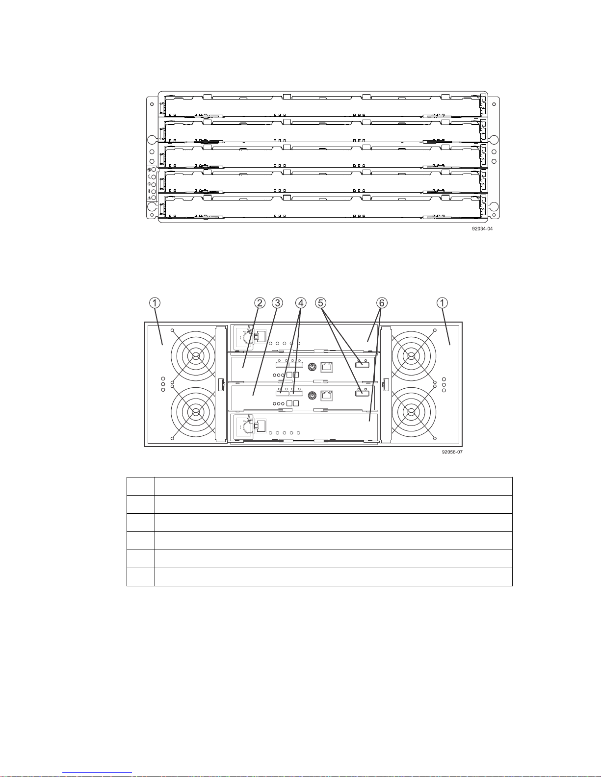
•
DE6600 drive tray – Rear view
Step 1 - Preparing to install a controller-drive tray |
27
1
Fan canister
2 ESM A
3 ESM B
4 Expansion port SFF-8088 connectors (IN)
5 Expansion port SFF-8088 connector (OUT)
6 Power canister
You can order an optional DC power supply connection and connector cables for the drive tray. A
qualified service person is required to make the DC power connection per NEC and CEC
guidelines . A two-pole 30-amp circuit breaker is required between the DC power source and the
drive tray for over-current and short-circuit protection. Before turning off any power switches on a
DC-powered drive tray, you must disconnect the two-pole 30-amp circuit breaker.
Warning: (W12) Risk of electrical shock –This unit has more than one power source. To remove
all power from the unit, all DC MAINS must be disconnected by removing all power connectors
(item 4 below) from the power supplies.
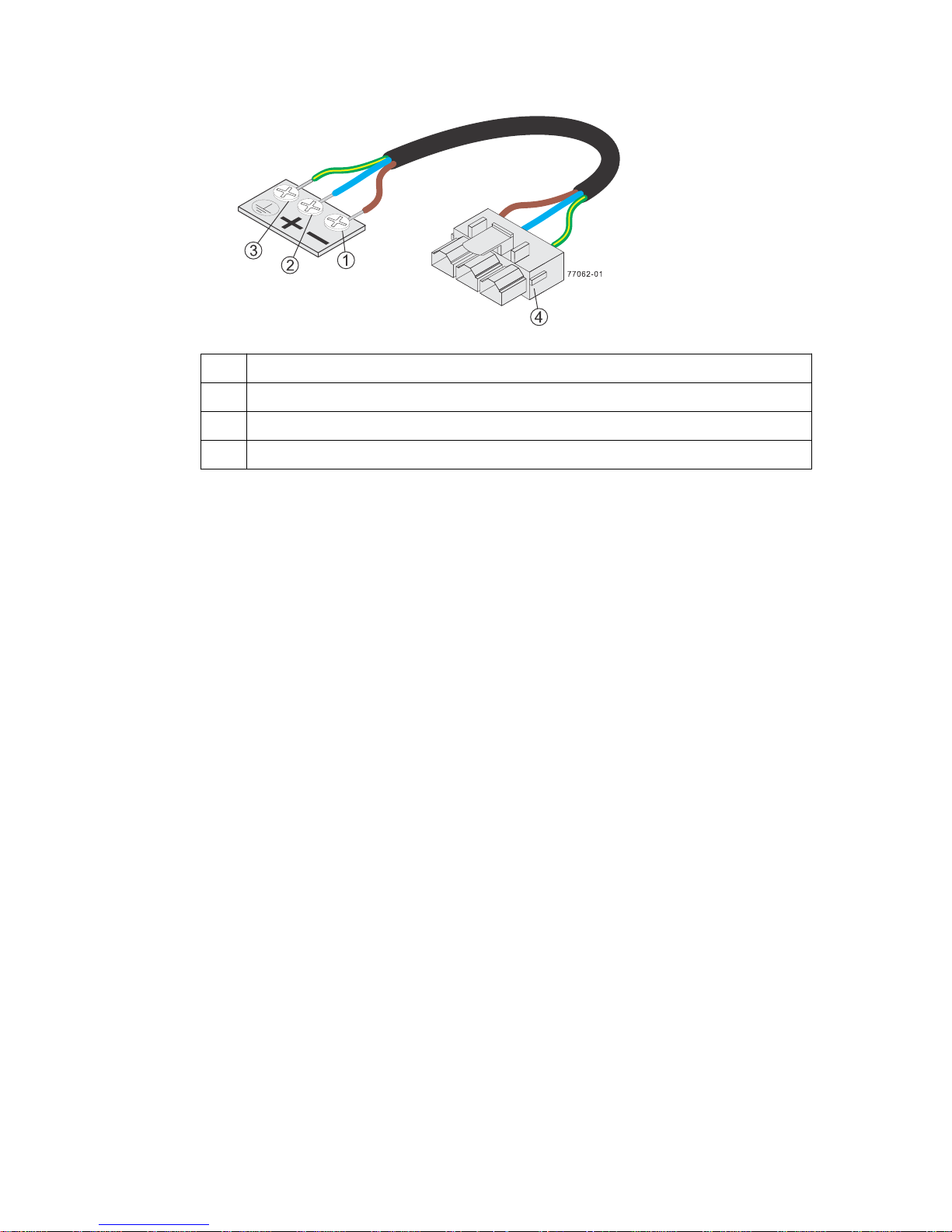
• DC power cable
Page 28
28 | E2700 Controller-Drive Tray and Related Drive Trays Installation Guide
1 Supply (Negative), Brown wire, -48 VDC
2 Return (Positive), Blue wire
3 Ground, Green/Yellow wire
4 DC power connector
See the
Storage System Site Preparation Guide
for information about the installation requirements
of the various controller-drive tray storage array components.
Page 29
Step 2 - Installing and configuring the switches
Things to know - Switches and routers
Note: Most of the switches and routers, as shipped from the vendor, require an update to either
their firmware or their settings to work correctly with the storage array.
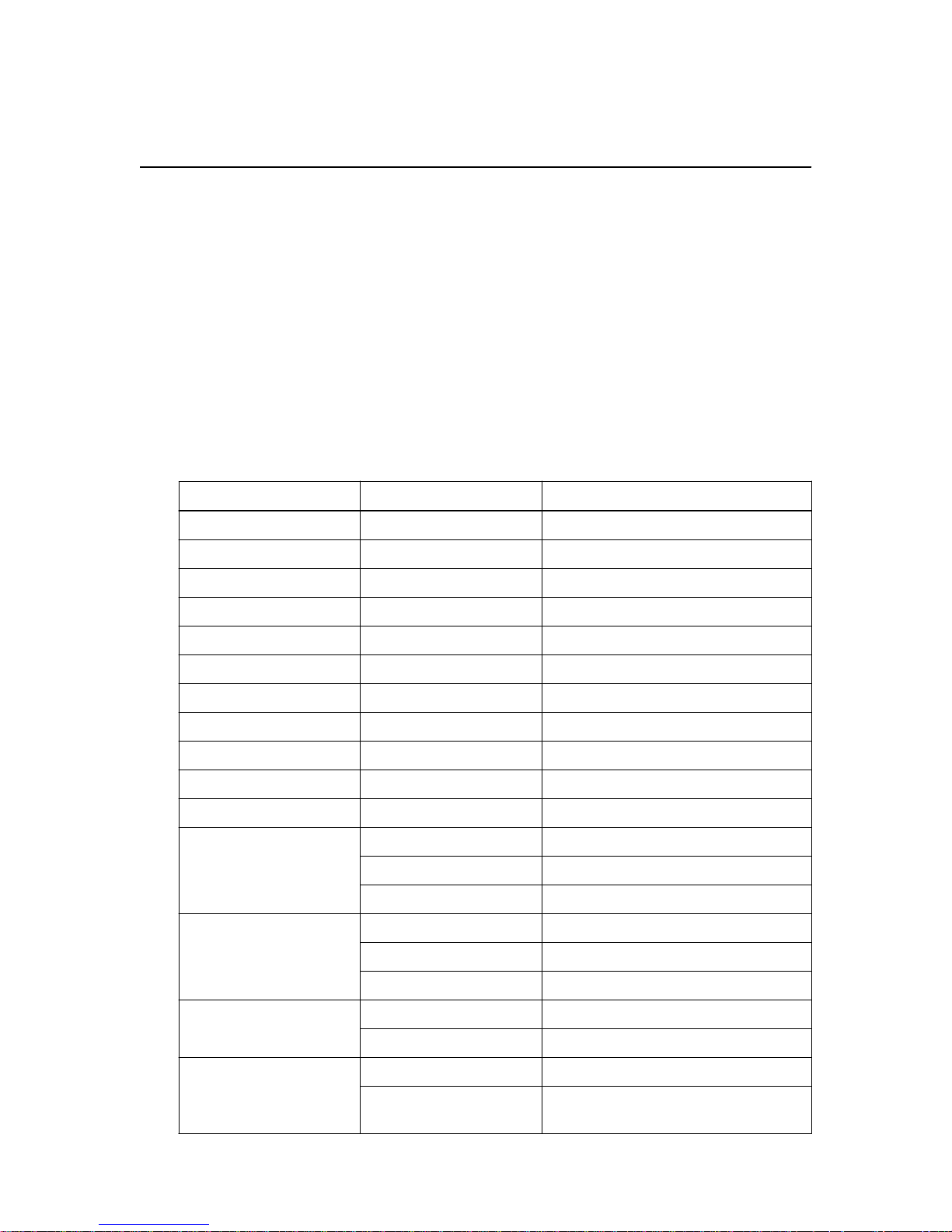
The switches and routers in the following tables are certified for use with an E2712 storage array, an
E2724 storage array, and an E2760 storage array using SANtricity Storage Manager Version 11.20.
29
If required, make the appropriate configuration changes for
the storage array.
See the switch’s documentation for information about how to install the switch or router and how to
use the configuration utilities that are supplied with the switch or router.
Table 7: Supported FC switches
Vendor
Brocade 300 8 Gb/s
Model Version/Data Rate
5100 8 Gb/s
5300 8 Gb/s
8000 8 Gb/s
DCX 8 Gb/s
DCX-4S 8 Gb/s
7800 EXT 8 Gb/s
6505 16 Gb/s
6510 16 Gb/s
6520 16 Gb/s
each
switch or router that is connected to
Qlogic SANbox 9000 8 Gb/s
Cisco 9148 8 Gb/s
Cisco Nexus 5010 8 Gb/s
HP Blade Center AW564A: Cisco MDS 8 Gb/s
DCX8510-x 16 Gb/s
5800 8 Gb/s
3800 8 Gb/s
9509 8 Gb/s
9513 8 Gb/s
5020 8 Gb/s
AJ821B: HP B-Series
8/24c
8 Gb/s
Page 30
30 | E2700 Controller-Drive Tray and Related Drive Trays Installation Guide
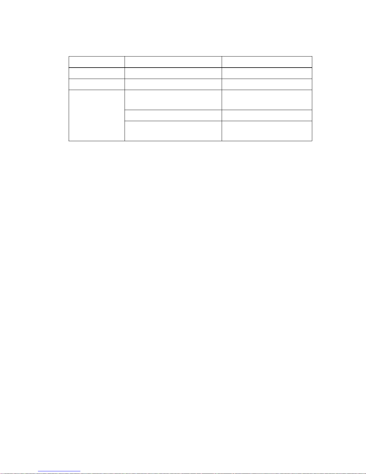
Table 8: Supported routers
Vendor Model Speed
Cisco 9222i 8Gb
Brocade 7800 8Gb
Qlogic 6240 8Gb FC
10 Gb iSCSI
6250 10 GbE iSCSI
6260 8Gb FC
10 Gb iSCSI
Contact technical support for the latest information about new switches that are tested and certified to
work with various hardware and software combinations.
Procedure - Installing and configuring switches
Steps
1. Install your switch according to the vendor’s documentation.
2. Contact technical support to obtain this information:
• The latest hardware compatibility information
• The models of the switches that are supported
• The firmware requirements and the software requirements for the switches
3. Update the switch’s firmware from the
This update might require that you cycle power to the switch.
NetApp Interoperability
site.
Page 31

Step 3 - Installing the host bus adapters for the
controller-drive tray
Key terms
Host bus adapter (HBA)
A physical board that resides in the host. The HBA provides for data transfer between the host and
the controllers in the storage array over the I/O host interface. Each HBA contains one or more
physical ports.
HBA host port
The physical and electrical interface on the host board adapter (HBA) that provides for the
connection between the host and the controller. Most HBAs have either one or two host ports. The
HBA has a unique World Wide Identifier (WWID) and each HBA host port has a unique WWID.
HBA host port world wide name (WWN)
31
A 16-character unique name that is provided for each port on the host bus adapter (HBA).
Network interface card (NIC)
A hardware component that connects the host to the controller.
Things to know - Host bus adapters and Ethernet Network
Interface Cards
• The E2700 controller-drive tray supports two native SAS host ports and the following host
interface cards (HICs):
◦ ⁃ A two-port or a four-port 12-Gb/s SAS HIC
⁃ A two-port 10-Gb/s iSCSI Base-T HIC (RJ-45)
⁃ A two-port or a four-port 10-Gb/s iSCSI
⁃ A two-port or a four-port 16-Gb/s Fibre Channel HIC
• The HBAs, HCAs, or NICs on a host must support the type of port (SAS, iSCSI, or Fibre
Channel) to which they connect on the controller-drive tray. For the best performance, HBAs,
HCAs, and NICs should support the highest data rate supported by the HICs to which they
connect.
Note: Some servers have GEN2 and GEN3 slots for HBAs. For the best performance, make
sure that GEN3 HBAs are installed in the GEN3 slots on the server.
• For maximum hardware redundancy, you must install a minimum of two HBAs, HCAs, or NICs
in each host. Using both ports of a dual-port HBA provides two paths to the storage array but does
not ensure redundancy if an HBA fails.
• You should not attach one host running two different protocols to one storage array at the same
time.
Page 32

| E2700 Controller-Drive Tray and Related Drive Trays Installation Guide
32
Note: Contact technical support to obtain information about the supported models of the HBAs,
HCAs, or NICs and their requirements to ensure that you have an acceptable configuration.
• Most of the HBAs, HCAs, and NICs, require updated firmware and software drivers to work
correctly with the storage array. For information about the updates, go to
NetApp Interoperability
Procedure - Installing host bus adapters
Steps
Check with technical support to make sure you have an acceptable configuration. Before
1.
installing an HBA, you must have the following information:
• The latest hardware compatibility information
• The models of the HBAs that are supported
• The firmware requirements and the software requirements for the HBAs
.
Refer to
2.
3. Install the latest version of the firmware and software drivers for the HBA. You can find the latest
version of the firmware for the HBA at
4. Check to see if the SMagent application is installed on all of your hosts:
• If Yes, you have completed this procedure.
• If No, continue with step 5 to obtain the HBA host port world wide name from the HBA BIOS
5. Reboot or start your host.
6. While your host is booting, look for the prompt to access the HBA BIOS utility.
7. Select each HBA to view its HBA host port world wide name.
8. Record the following information for each host and for each HBA connected to the storage array:
• The name of each host
• The HBAs in each host
NetApp Interoperability
Note: If your operating system is either Windows Server 2008 Server Core, or Windows 2012
Sever, you might have additional installation requirements. Refer to the Microsoft Developers
Network (MSDN) for more information about Windows Server 2008 Server Core. You can
access these resources from
utility.
for more information about installing the HBA.
msdn.microsoft.com
NetApp Interoperability
.
.
• The HBA host port world wide name of each port on the HBA
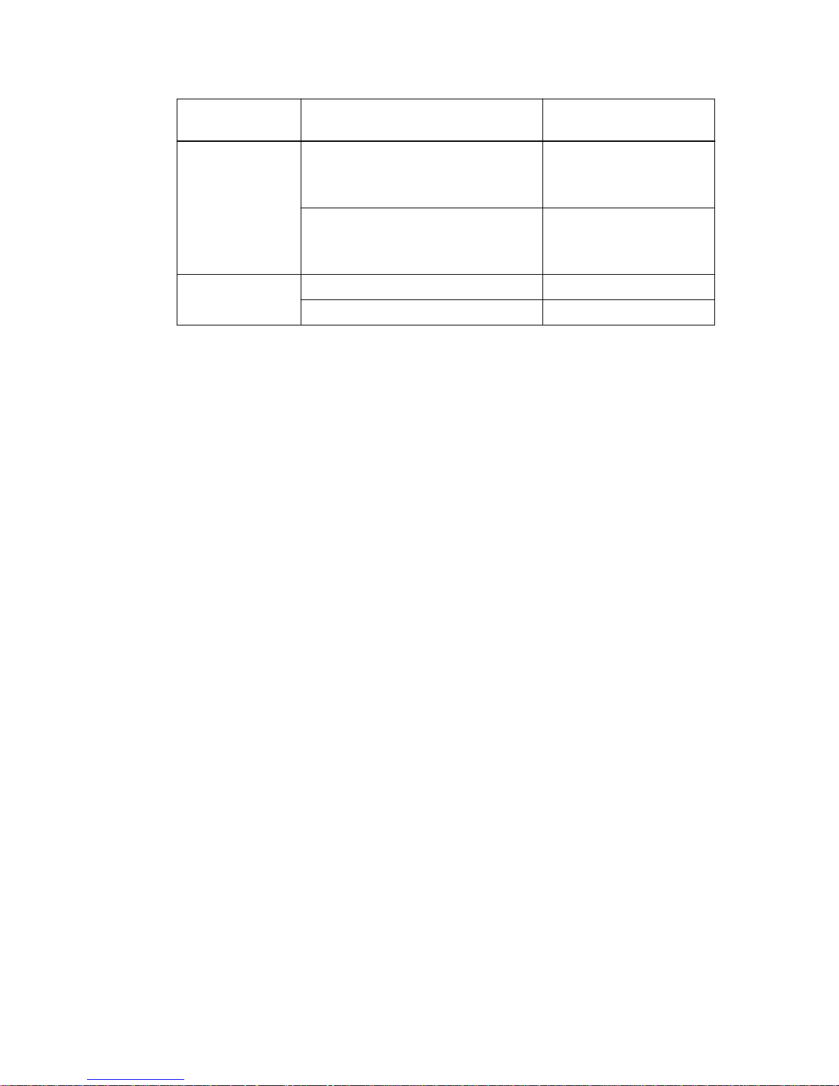
The following table shows examples of the host and HBA information that you must record.
Page 33
Step 3 - Installing the host bus adapters for the controller-drive tray | 33
Host name Associated HBA HBA host port world wide
name
ENGINEERING Vendor x, Model y (dual port)
• 37:38:39:30:31:32:33:32
• 37:38:39:30:31:32:33:33
Vendor a, Model y (dual port)
• 42:38:39:30:31:32:33:42
• 42:38:39:30:31:32:33:44
FINANCE Vendor a, Model b (single port) 57:38:39:30:31:32:33:52
Vendor x, Model b (single port) 57:38:39:30:31:32:33:53
Page 34

34
Step 4 - Installing the controller-drive tray
Things to know - General installation
The power supplies meet standard voltage requirements for both domestic and worldwide operation.
Note: Ensure that the combined power requirements of your trays do not exceed the power
capacity of your cabinet. For power ratings on the and its related drive trays, refer to the
Preparation Guide
.
Procedure - Installing the E2712 or E2724 controller-drive
tray
About this task
Warning: (W08) Risk of bodily injury – Two persons are required to safely lift the component.
Site
Warning: (W05) Risk of bodily injury – If the bottom half of the cabinet is empty, do not install
components in the top half of the cabinet. If the top half of the cabinet is too heavy for the bottom
half, the cabinet might fall and cause bodily injury. Always install a component in the lowest
available position in the cabinet.
You can install the controller-drive tray into an industry-standard cabinet.
This procedure describes how to install the mounting rails into an industry-standard cabinet.
Attention: Possible hardware damage – To prevent electrostatic discharge damage to the tray,
use proper antistatic protection when handling tray components.
Steps
1. Ensure that the cabinet is in the final location and the cabinet installation site meets the clearance
requirements for air flow as shown in the figures.
Note: Fans pull air through the tray from front to back across the drives.
Page 35
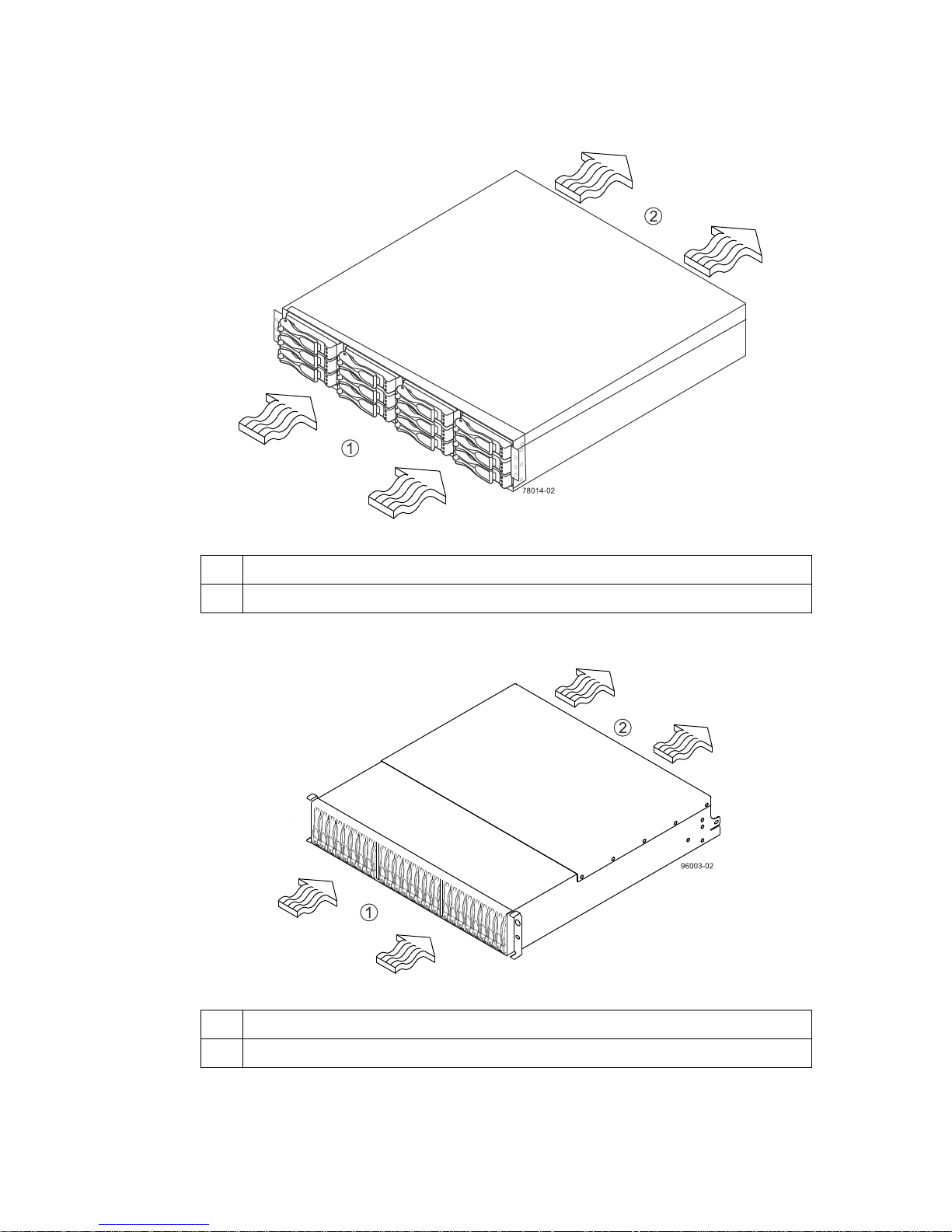
Step 4 - Installing the controller-drive tray |
E2712 controller-drive tray – Airflow and clearance requirements
35
1
76 cm (30 in.) clearance in front of the cabinet
2 61 cm (24 in.) clearance behind the cabinet
E2724 controller-drive tray – Airflow and clearance requirements
76 cm (30 in.) clearance in front of the cabinet
1
2 61 cm (24 in.) clearance behind the cabinet
2. Lower the feet on the cabinet, if required, to keep it from moving.
3. Remove the controller-drive tray and all contents from the shipping carton.
Page 36
| E2700 Controller-Drive Tray and Related Drive Trays Installation Guide
36
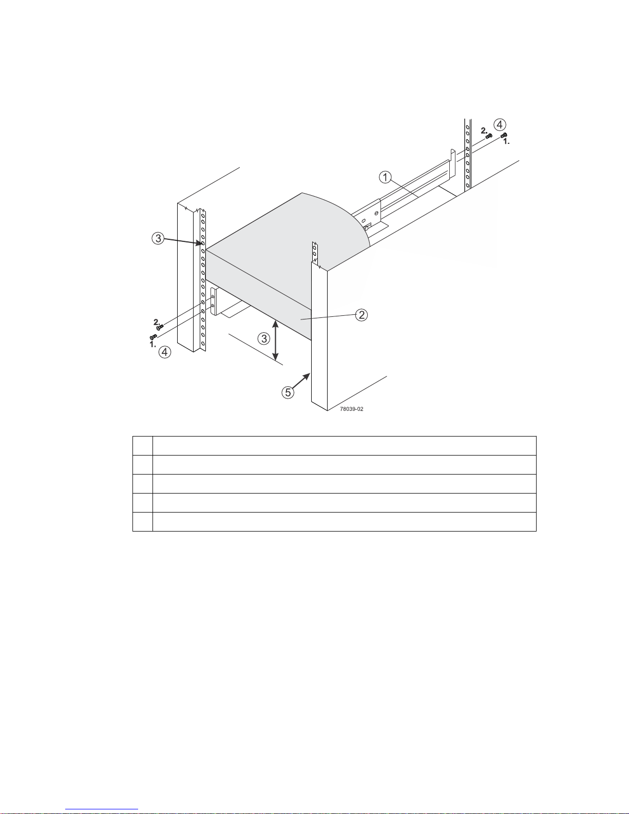
4. Position the mounting rails in the cabinet. For more information, refer to the installation
instructions that are included with your mounting rails.
1
Mounting rail
2 Existing tray
3 Clearance above and below the existing tray
4 Screws for securing the mounting rail to the cabinet (front and rear)
5 Industry-standard cabinet
• If you are installing the mounting rails above an existing tray, position the mounting rails
directly above the existing tray.
• If you are installing the mounting rails below an existing tray, allow 8.7-cm (3.4 in.) clearance
below the existing tray for the E2712 controller-drive trays and 8.9-cm (3.5 in.) for the E2724
controller-drive trays.
Attention: Risk of equipment malfunction – To avoid exceeding the functional and
environmental limits, install only drives that have been provided or approved by NetApp, Inc.
Not all controller-drive trays are shipped with pre-populated drives. System integrators,
resellers, system administrators, or users of the controller-drive tray can install the drives.
5. Attach the mounting rails to the cabinet.
a. Ensure that the adjustment screws on the mounting rail are loose so that the mounting rail can
extend or contract as needed.
Page 37
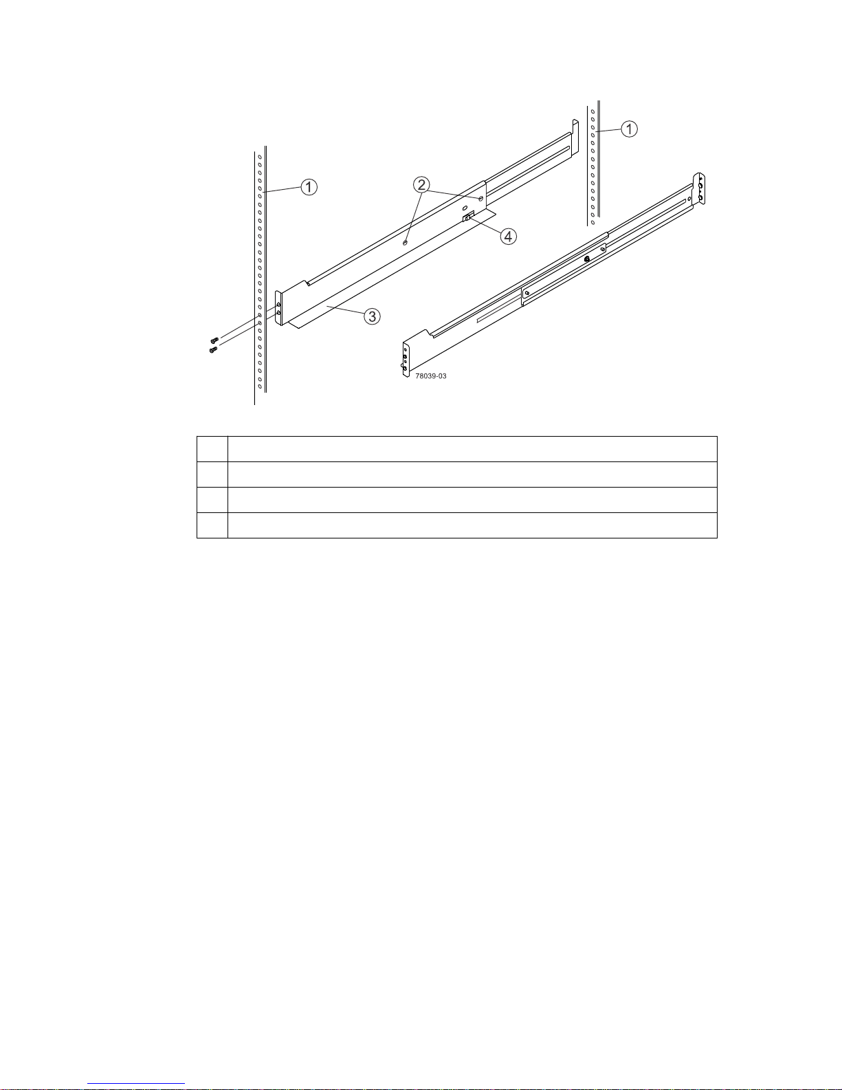
1
Cabinet mounting holes
Step 4 - Installing the controller-drive tray |
37
2 Adjustment screws for locking the mounting rail length
3 Mounting rails
4 Clip for securing the rear of the controller-drive tray
b. Place the mounting rail inside the cabinet, and extend the mounting rail until the flanges on
the mounting rail touch the inside of the cabinet.
c. Ensure that the alignment spacers on the front flange of the mounting rail fit into the mounting
holes in the cabinet.
The front flange of each mounting rail has two alignment spacers. The alignment spacers are
designed to fit into the mounting holes in the cabinet. The alignment spacers help position and
hold the mounting rail.
Note: If the cabinet in which you are installing this tray has square holes, insert the
shoulder washers into the square holes when mounting the rail.
Page 38
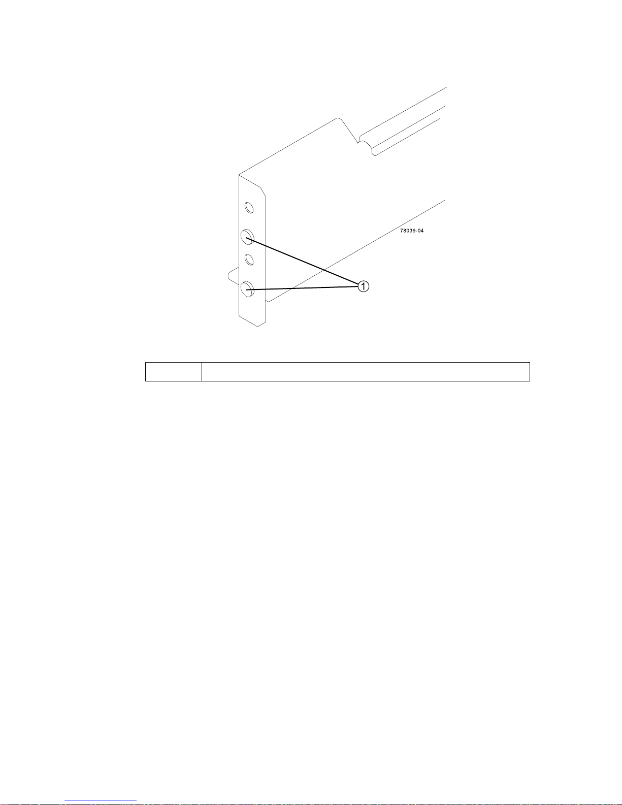
38 | E2700 Controller-Drive Tray and Related Drive Trays Installation Guide
1
Alignment spacers
d. Insert one M5 screw through the front of the cabinet and into the top captured nut in the
mounting rail. Tighten the screw.
e. Insert two M5 screws through the rear of the cabinet and into the captured nuts in the rear
flange in the mounting rail. Tighten the screws.
f. Tighten the adjustment screws on the mounting rail.
g. Repeat these steps to install the second mounting rail.
6. With the help of one other person, slide the rear of the controller-drive tray onto the mounting
rails. The rear edge of the controller-drive tray must fit into the clip on the mounting rail. The
controller-drive tray is correctly aligned when these conditions are met:
• The mounting holes on the front flanges of the drive tray align with the mounting holes on the
front of the mounting rails. See item 4 in the following figure.
• The rear edge of the controller-drive tray sheet metal fits into the clip on the mounting rail.
• The holes in the controller-drive tray sheet metal for the rear hold-down screws align with the
captured nuts in the side of the mounting rails.
Page 39
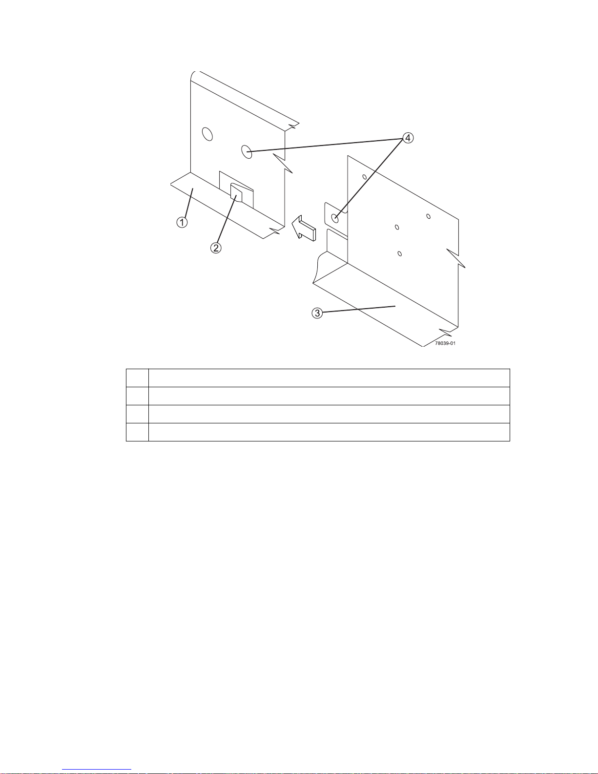
Step 4 - Installing the controller-drive tray |
39
1
Mounting rail
2 Clip
3 Partial view of the controller-drive tray rear sheet metal
4 Mounting holes
7. Secure the front of the controller-drive tray to the cabinet. Use the two screws to attach the flange
on each side of the front of the controller-drive tray to the mounting rails.
a. Insert one M5 screw through the bottom hole of a flange on the controller-drive tray so that
the screw goes through the cabinet rail and engages the bottom captured nut in the mounting
rail. Tighten the screw.
b. Repeat the step for the second flange.
Note: The rear of the controller-drive tray contains two controllers. The top of the
controller-drive tray is the side with the labels.
8. Secure the side of the controller-drive tray to the mounting rails by performing these steps:
a. Insert one M4 screw through the side sheet metal of the controller-drive tray into the captured
nut on the side of the mounting rail. Tighten the screw.
b. Repeat the step for the other side.
9. Attach the plastic end caps onto the front of the controller-drive tray.
a. Put the top of the end cap on the hinge tab that is part of the controller-drive tray mounting
flange.
b. Gently press on the bottom of the end cap until it snaps into place over the retainer on the
bottom of the controller-drive tray mounting flange.
Page 40
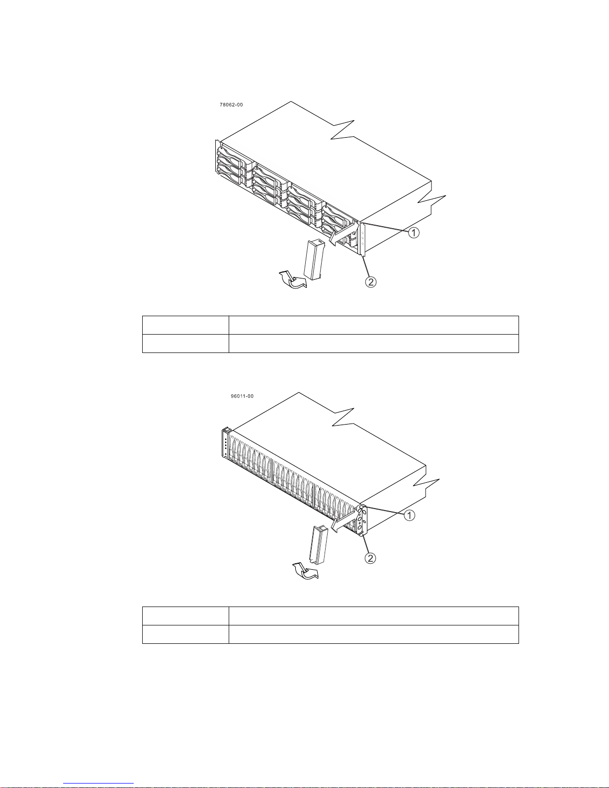
| E2700 Controller-Drive Tray and Related Drive Trays Installation Guide
40
Attaching the end caps to the E2712 controller-drive tray
1
Hinge tab
2 Retainer
Attaching the end caps to the E2724 controller-drive tray
1
2 Retainer
10. Install the drive trays.
Hinge tab
Page 41
Step 4 - Installing the controller-drive tray | 41
Procedure - Installing drives in the E2712 or E2724
controller-drive tray
About this task
In some situations, the controller-drive tray might be delivered without the drives installed. Follow
the steps in this procedure to install the drives. If your controller-drive tray already has drives
installed, you can skip this step and go to
page 54.
Attention: Risk of equipment malfunction – To avoid exceeding the functional and
environmental limits, install only drives that have been provided or approved by NetApp, Inc.
Drives might be shipped but not installed. System integrators, resellers, system administrators, or
users can install the drives.
Note: The installation order is from top to bottom and from left to right.The installation order is
important because the drives might already contain configuration information that depends upon
the correct sequence of the drives in the tray.
Step 5 - Connecting the controller-drive tray to the hosts
on
Steps
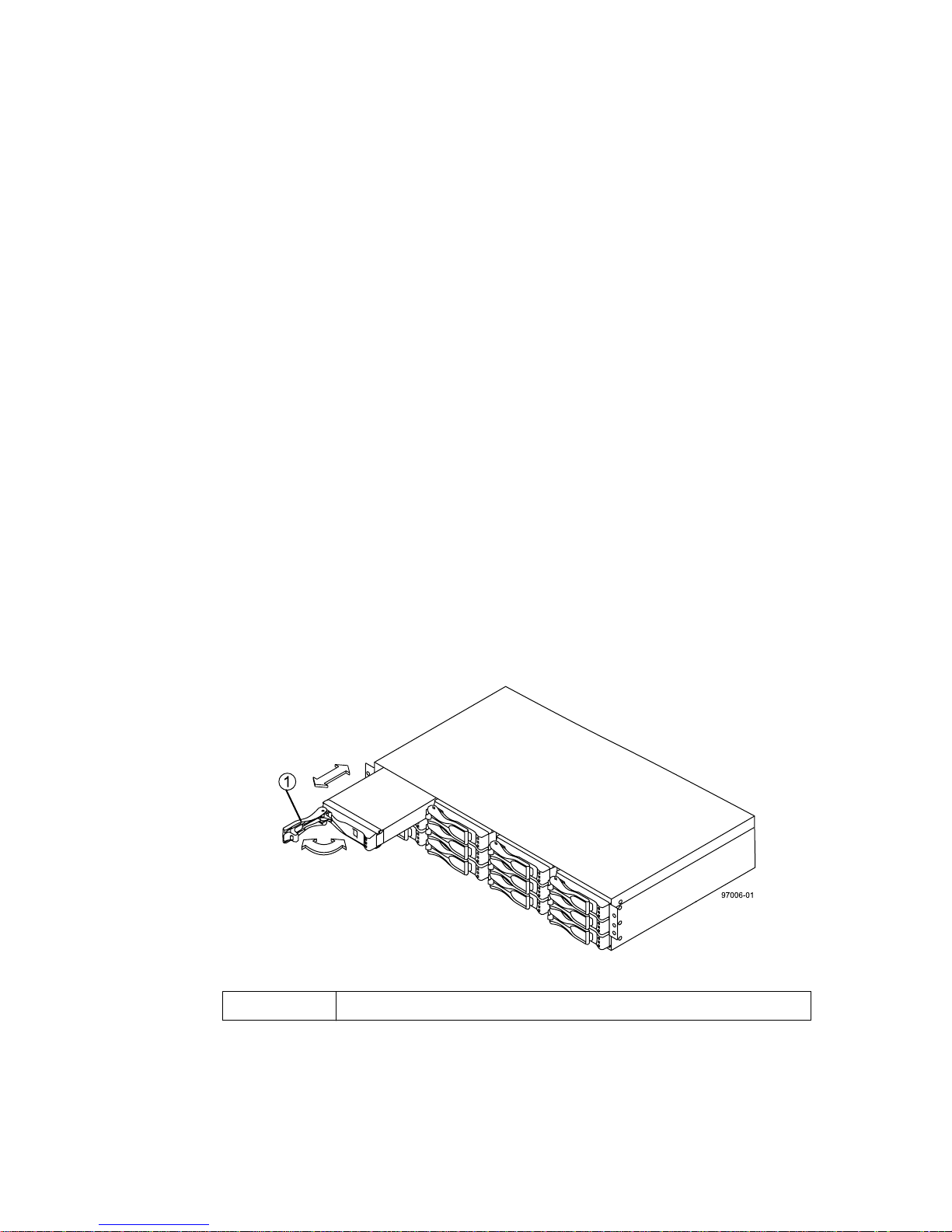
1. Beginning with the first drive slot (the upper-left slot), place the drive in the slot guides, and slide
the drive all the way into the slot.
2. Push the drive handle to the right (in E2712) or down (in E2724) to lock the drive securely in
place.
• Installing a drive in the E2712 controller-drive tray
1
Drive handle
Page 42

| E2700 Controller-Drive Tray and Related Drive Trays Installation Guide
42
• Installing a drive in the E2724 controller-drive tray
1
Note: In some applications, the drive handle might have the hinge on the right.
Drive handle
3. Install the second drive beneath the first drive (E2712 controller-drive tray) or to the right of the
first drive (E2724 controller-drive tray).
4. Install the other drives from top to bottom and then from left to right (E2712 controller-drive tray)
or to the right (E2724 controller-drive tray).
Procedure - Installing the E2760 controller-drive tray
About this task
Attention: Risk of equipment malfunction – To avoid possible equipment damage and ensure
safe and efficient servicing of the equipment, install the 60-drive trays toward the bottom of a
cabinet.
You can install the controller-drive tray into an industry-standard cabinet, provided it has a depth of
100 cm (40 in.). A minimum depth of 76 cm (30 in.) between the front EIA support rails and the rear
EIA support rails is required.
Note: If you are installing the controller-drive tray in a cabinet with square holes, use the eight
4
conical washers in the rail kit to align the screws in the holes (see step
through step 7).
Steps
1. Ensure that the cabinet is in the final location and you meet the clearance requirements shown in
the following figure.
Page 43
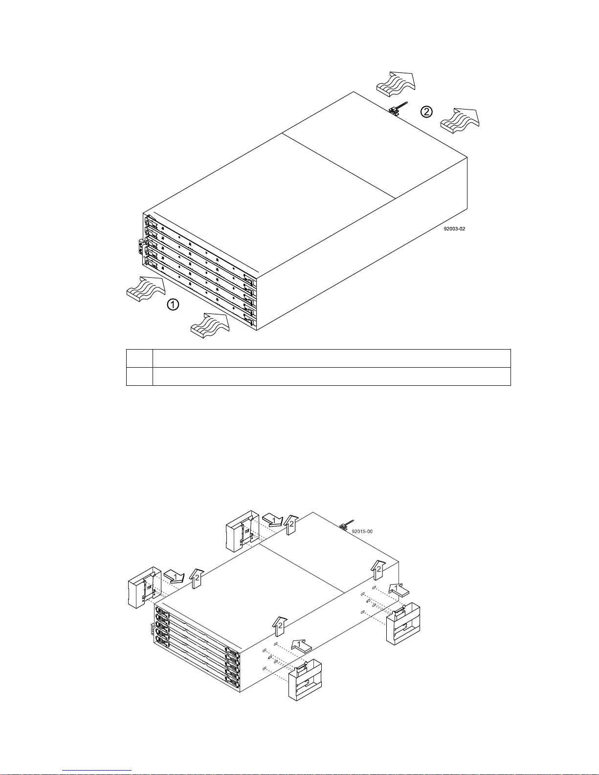
Step 4 - Installing the controller-drive tray |
43
1 81 cm (32 in.) clearance in front of the cabinet
2 61 cm (24 in.) clearance behind the cabinet
Note: Fans pull air through the controller-drive tray from front to back across the drives.
2. Lower the feet on the cabinet to keep the cabinet from moving.
3. Before removing the controller-drive tray and all of the contents from the shipping carton, locate
the tray handles and attach them to the controller-drive tray:
a. Align the handle just under the thumb latch.
b. Push the handle up until it clicks in place with the thumb latch.
Page 44
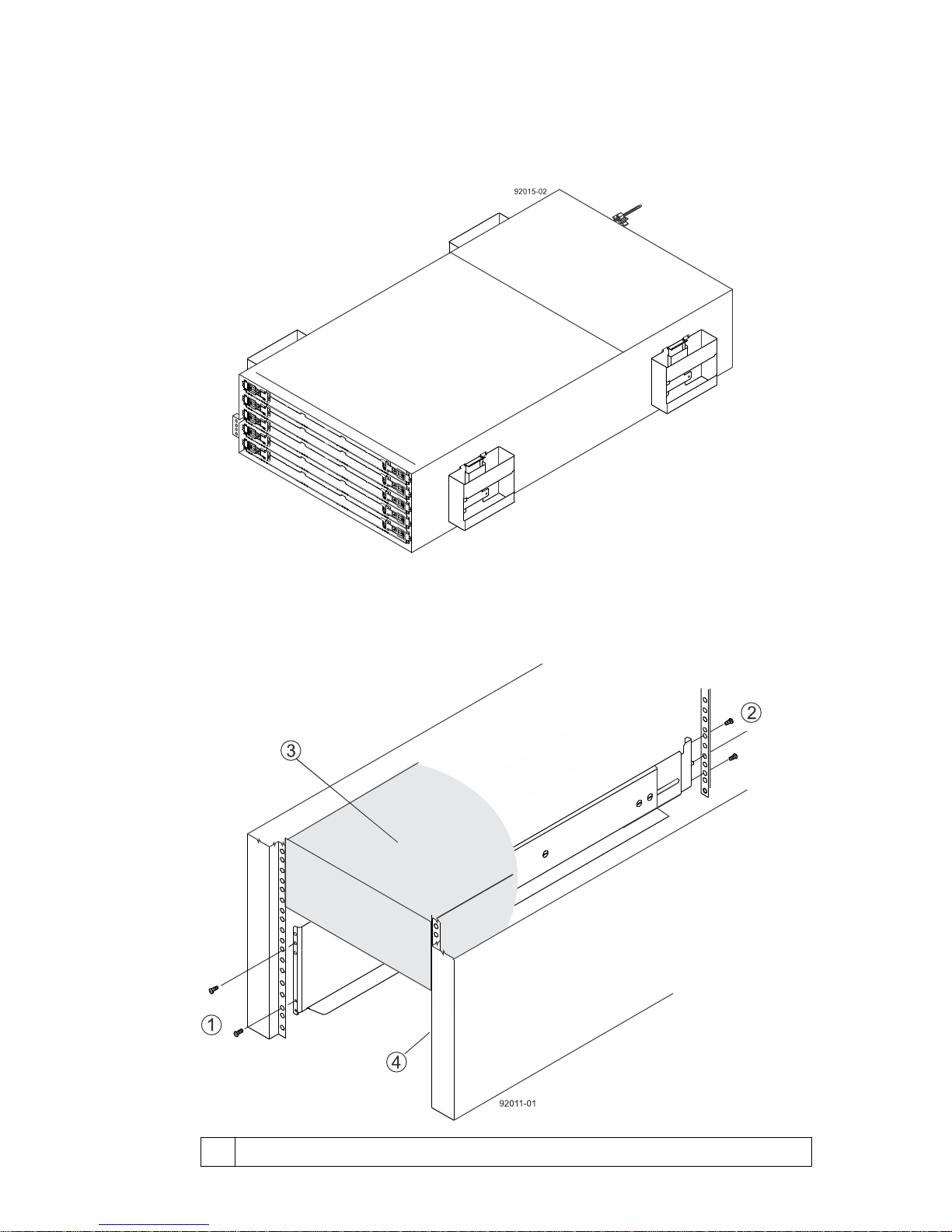
44 | E2700 Controller-Drive Tray and Related Drive Trays Installation Guide
4. With the help of at least three other persons, remove the controller-drive tray and all of the
contents from the shipping carton, using the four controller-drive tray handles (two to a side) as
shown in the following figure. Set the controller-drive tray aside.
Warning: (W10)Risk of bodily injury – Four or more persons are required to safely lift the
component.
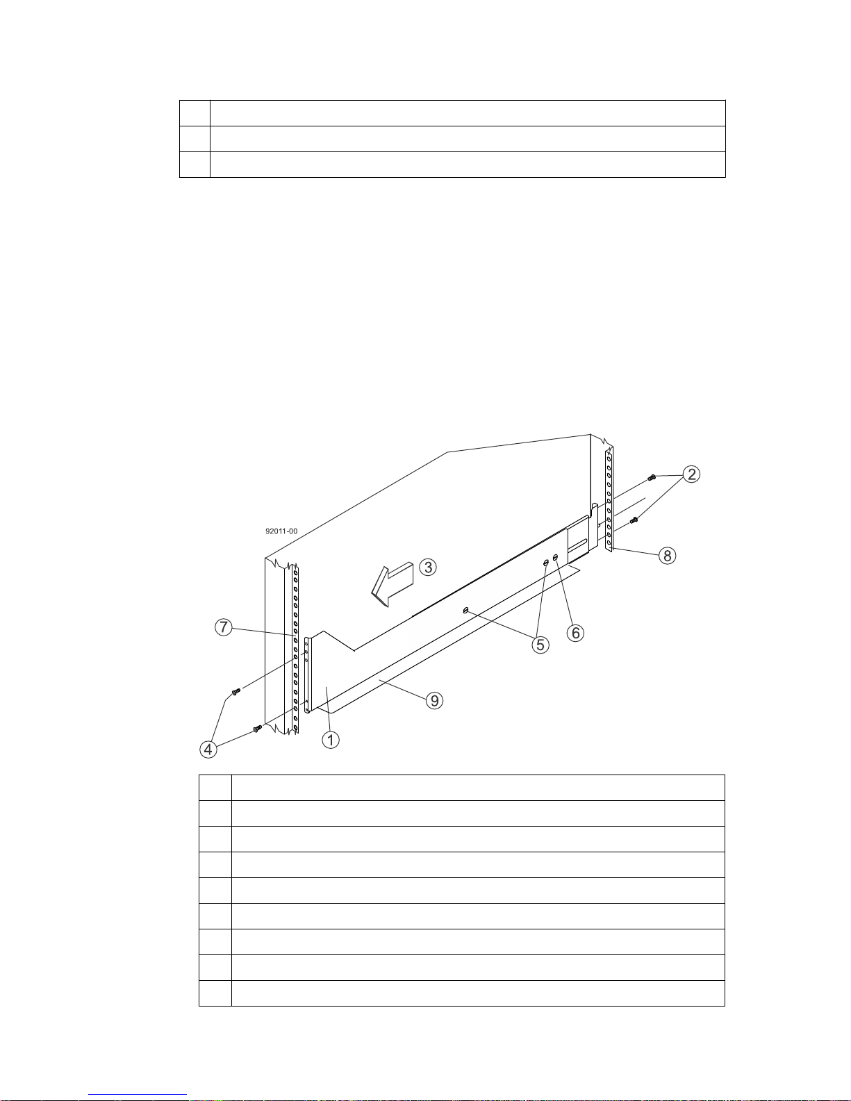
5. Position the mounting rails in the cabinet as shown in the following figure.
1
Screws for securing the mounting rail to the cabinet (front)
Page 45
Step 4 - Installing the controller-drive tray |
2 Screws for securing the mounting rail to the cabinet (rear)
3 Existing tray
4 Industry standard cabinet
• If you are installing the mounting rails above an existing tray, position the mounting rails
directly above the tray.
• If you are installing the mounting rails below an existing tray, allow 17.8-cm (7-in.) vertical
clearance for the controller-drive tray.
To attach the mounting rails to the cabinet, perform one of the following actions:
6.
• If you are using the long, fixed-size mounting rails, go to step 7.
• If you are using the shorter adjustable mounting rails, go to step 8.
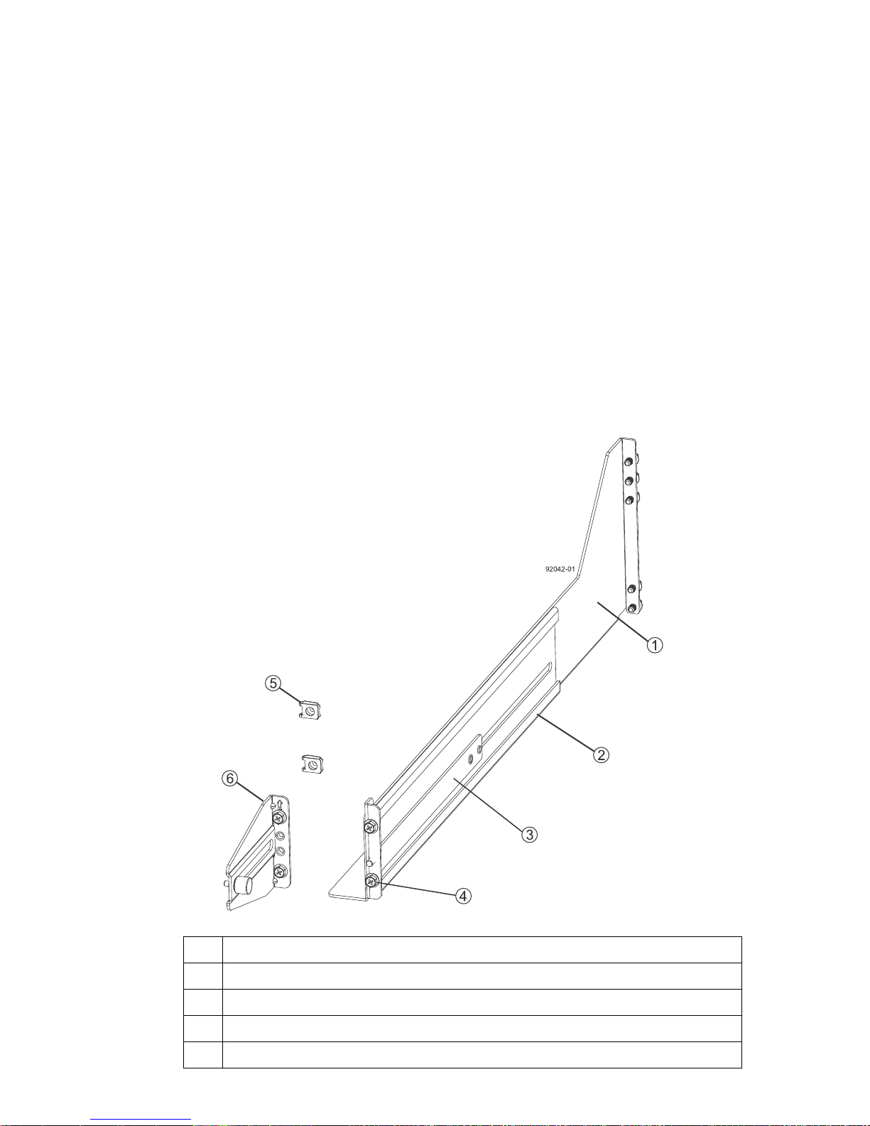
Attach the long, fixed-size rails to the cabinet.
7.
a. Ensure that the adjustment screws on the mounting rail are loose so that the mounting rail can
extend or contract as needed.
45
1
Front of the mounting rail
2 Two M5 screws for the rear EIA support rail
3 Front of the cabinet
4 Two M5 screws for the front EIA support rail
5 Adjustment screws
6 Rear hold-down screw
7 Cabinet mounting holes on the front EIA support rail
8 Cabinet mounting holes on the rear EIA support rail
9 Mounting rail lip
b. Remove the rear hold-down screw. It protrudes from the inside of the rail and prevents you
from sliding the controller-drive tray onto the rails.
Page 46
46 | E2700 Controller-Drive Tray and Related Drive Trays Installation Guide
c. Place the mounting rail inside the cabinet, and extend the mounting rail until the flanges on
the mounting rail touch the inside of the cabinet.
d. Insert one M5 screw through the front of the cabinet, and screw it into the top captured nut in
the mounting rail.
e. Insert two M5 screws through the rear of the cabinet, and screw them into the captured nuts in
the rear flange in the mounting rail.
f. Counting up from the bottom of the mounting rail, place the bottom of the screw of the rear
bracket in the 8th hole of the cabinet so that the top of the rear bracket is in the 11th hole. The
distance between the two holes should be 1U or 4.45 cm (1.75 in).
g. Tighten the adjustment screws on the mounting rail.
h. Repeat these steps to install the second mounting rail.
i. Insert one M5 screw through the front of the mounting rail. You use this screw to attach the
controller-drive tray to the cabinet.
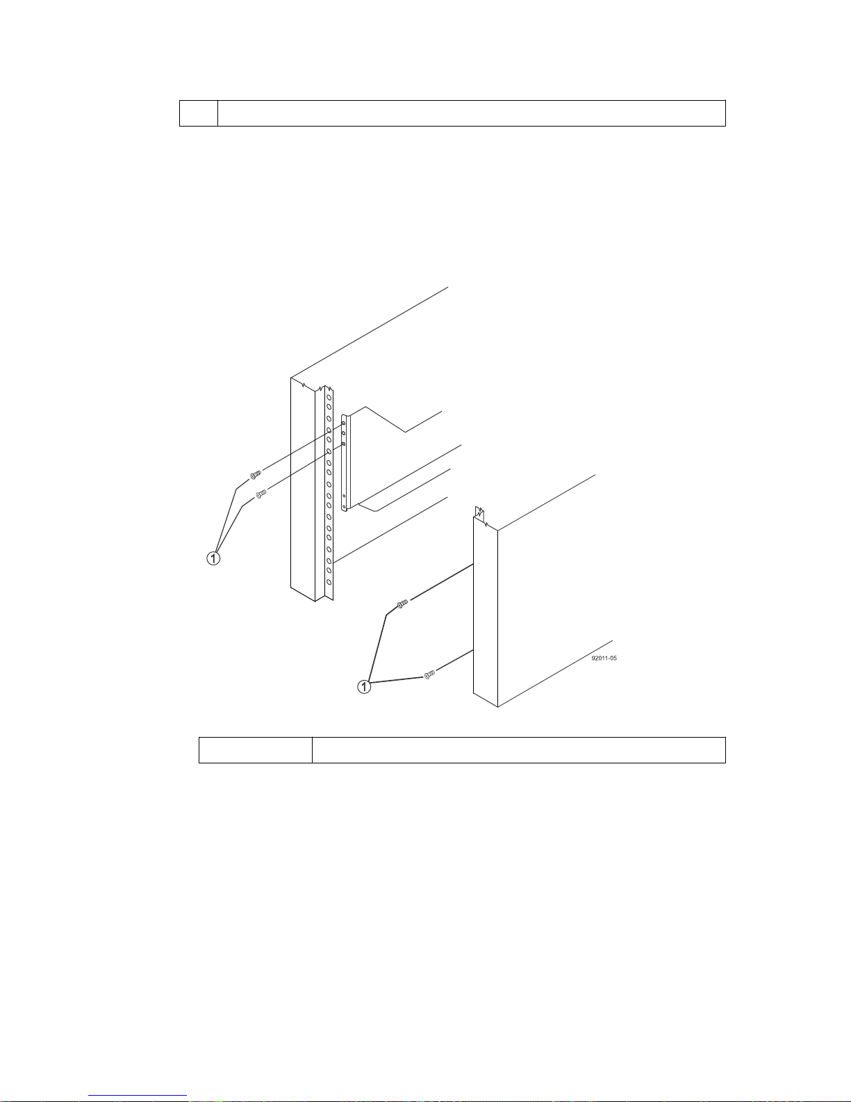
Attach the shorter, adjustable size mounting rails to the cabinet.
8.
1
Front of the mounting rail
2 Rear of the mounting rail
3 Rail fix bar
4 Two M5 screws for the front EIA support rail
5 Two clips for the front EIA support rail
Page 47
Step 4 - Installing the controller-drive tray |
6 Rear bracket
a. Ensure that the adjustment screws on the mounting rail are loose but not detached so that the
mounting rail can extend or contract as needed.
b. Place the mounting rail inside the cabinet, and extend the mounting rail until the flanges on
the mounting rail touch the inside of the cabinet.
c. Insert two M5 screws through the front of the cabinet, and screw them into the second and
fourth threaded holes from the top captured nut in the mounting rail.
47
1 M5 screws
d. Insert two M5 screws through the rear of the cabinet, and screw them into the captured nuts in
the rear flange in the mounting rail.
e. Counting up from the bottom of the mounting rail, place the bottom screw of the rear bracket
in the 8th hole of the cabinet so that the top of the rear bracket is in the 11th hole. The
distance between the two holes should be 1U or 4.45 cm (1.75 in).
f. Tighten the adjustment screws on the mounting rail.
g. Repeat these steps to install the second mounting rail.
h. Insert one M5 screw through the front of the mounting rail. This screw attaches the controller-
drive tray to the cabinet.
Page 48
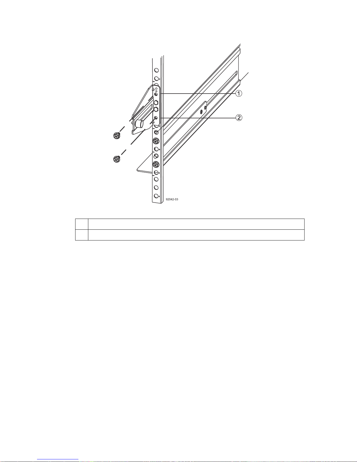
| E2700 Controller-Drive Tray and Related Drive Trays Installation Guide
48
1 Top cabinet mounting hole on the rear EIA support rail
2 Bottom cabinet mounting hole on the rear EIA support rail
9. Remove the bezel from the front of the controller-drive tray.
10. With the help of at least three other persons, slide the rear of the controller-drive tray onto the
mounting rails. The controller-drive tray is correctly aligned when the mounting holes on the
front flanges of the controller-drive tray align with the mounting holes on the front of the
mounting rails.
Warning: (W10) Risk of bodily injury – Four or more persons are required to safely lift the
component.
11. After the controller-drive tray is correctly aligned, remove the enclosure lift handles as shown in
the figure:
a. Use your thumb to unlatch and remove the rear controller-drive tray lift handles (two to a
side).
b. Use the front controller-drive tray lift handles to slide the drive tray all the way into the
cabinet.
c. After the drive tray is secure in the cabinet, use your thumb to unlatch and remove the front
controller-drive tray lift handles (two to a side).
d. Insert the remainder of the tray into the cabinet.
Page 49
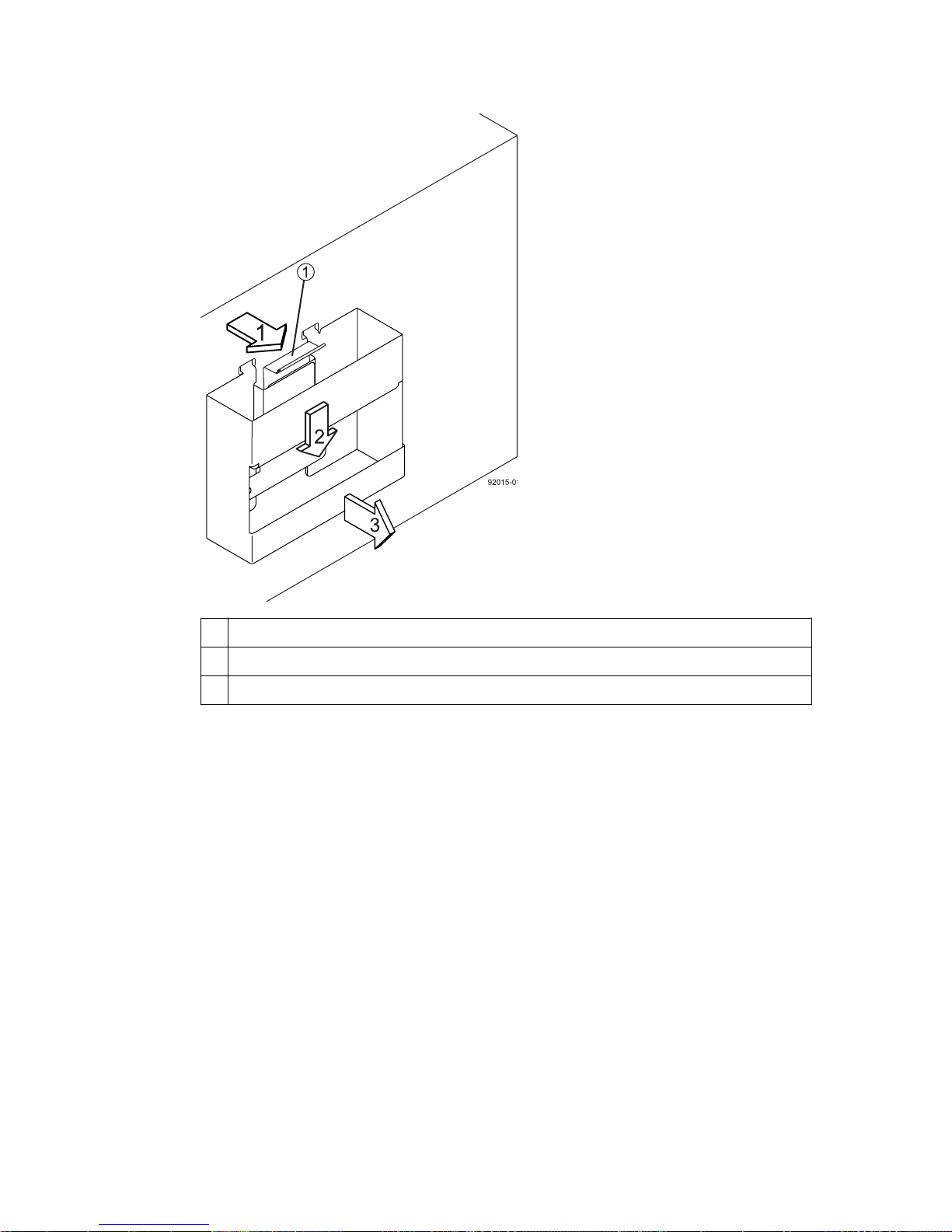
Step 4 - Installing the controller-drive tray |
49
1 Pull the thumb latch away from the controller-drive tray to detach the hook.
2 Shift the handle down to release the other four hooks.
3 Move the handle away from the controller-drive tray.
12. Secure the front of the controller-drive tray to the cabinet. Use the four screws to attach the flange
on each side of the front of the controller-drive tray to the mounting rails.
a. Insert two M5 screws through the bottom holes of a flange on the controller-drive tray so that
the screws go through the EIA support rail and engage the bottom captured nuts in the
mounting rail. Tighten the screws.
You had attached the second and fourth threaded holes in step
8.c
.
b. Repeat this step for the second flange.
13. Secure the side of the controller-drive tray to the mounting rails.
a. Tighten the thumbscrew on the rear mounting bracket that you installed in step
7.f
to secure
the controller-drive tray to the mounting rails.
b. Repeat this step for the other side.
Note: Ensure that each drive drawer in the controller-drive tray is securely latched to ensure
proper air flow to the drives.
14. Attach the bezel onto the front of the controller-drive tray.
Page 50
| E2700 Controller-Drive Tray and Related Drive Trays Installation Guide
50
Procedure - Installing drives in the E2760 controller-drive
tray
About this task
The controller-drive tray is shipped with the drive drawers installed, but the drives are not installed.
Follow the steps in this procedure to install the drives.
Attention: Risk of equipment malfunction – To avoid exceeding the functional and
environmental limits, install only drives that have been provided or approved by NetApp, Inc.
Drives might be shipped but not installed. System integrators, resellers, system administrators, or
users can install the drives.
Attention: Risk of equipment malfunction – All 60-drive trays have a limit of five solid state
drives (SSDs) per drawer. If you exceed this limit for SSDs in a particular drawer, the power
source in the drawer could fail.
1
If you are installing fewer than 60 drives, if you have SSDs, or if your drives have different
capacities, do the following:
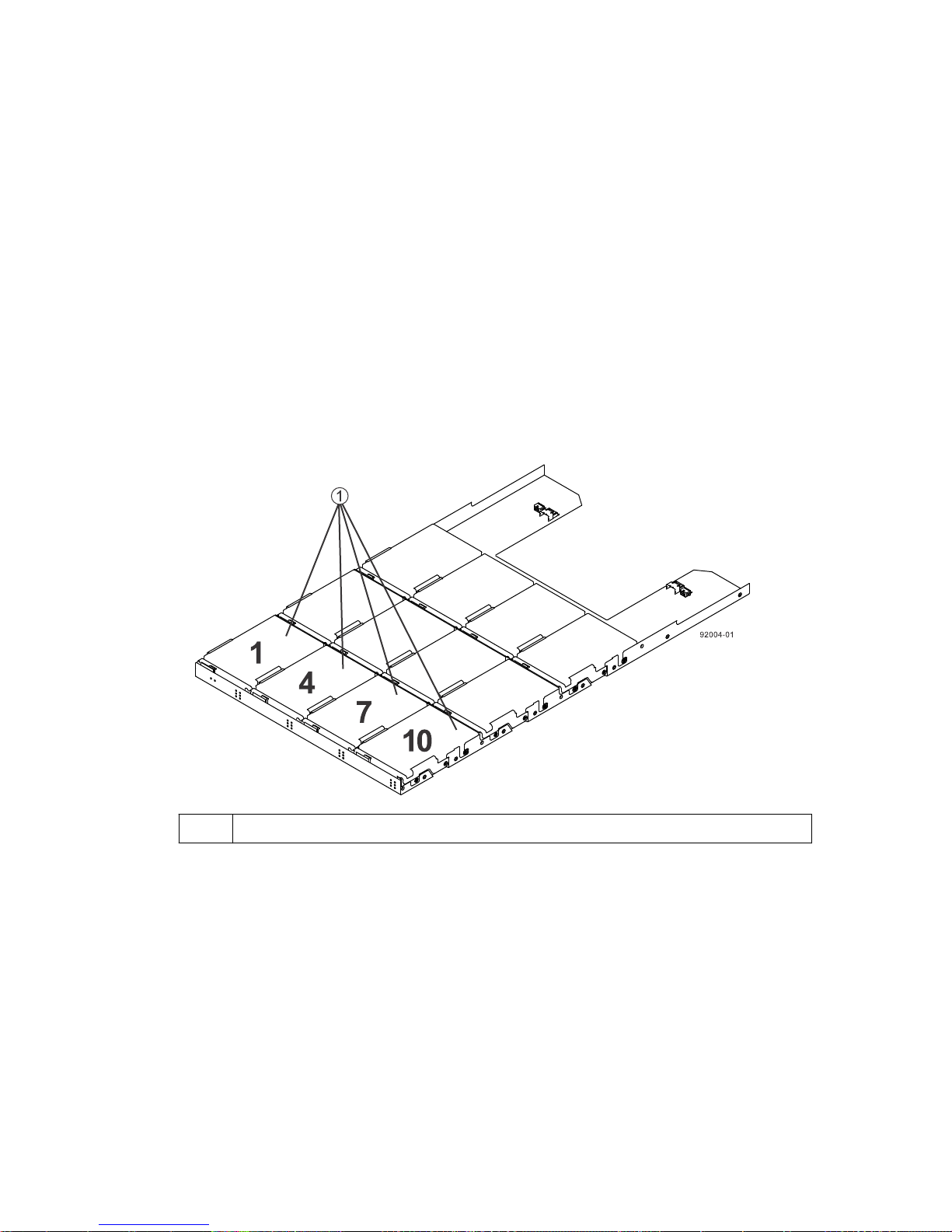
• Install the drives in the front four slots (shown in the figure as slots 1,4, 7, and 10) of each drawer
• Distribute any remaining drives across the drawers.
• Distribute any SSDs evenly across the drawers.
• Do not install more than five SSDs in each drawer (no more than 25 SSDs in each tray). The
Attention: Risk of equipment damage – If you want to move the 60-drive tray to a new location
after installing the drives, you must remove all of the drives from the drive tray following proper
Slots requiring drives in each drawer
to maintain adequate airflow for cooling. You must install at least 20 drives in the tray.
You must install an equal number of each type of drive in each drawer to use the Drawer Loss
Protection (DLP) feature in SANtricity software. If you have extra drives, you can install them,
but they will not be used for DLP.
power source in the drawer can fail.
Page 51
Step 4 - Installing the controller-drive tray |
51
drive-removal procedures. Never ship a 60-drive tray with drives installed. See
Removing drives from a 60-drive tray
for instructions on how to remove the drives from the 60-
Procedure -
drive tray.
Steps
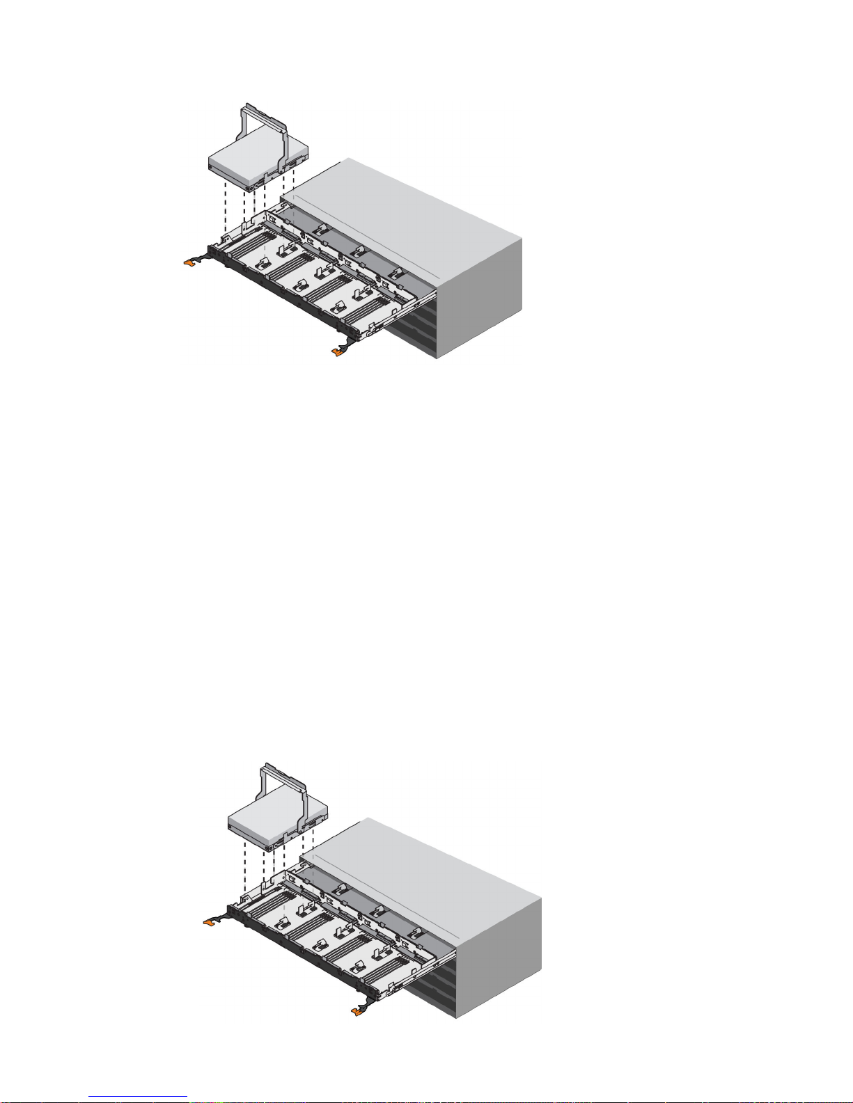
1. Unlatch the top drive drawer by pulling out on both levers at the front of the drawer.
2. Using the extended levers, carefully pull the drive drawer out until it stops. Do not completely
remove the drive drawer from the controller-drive tray.
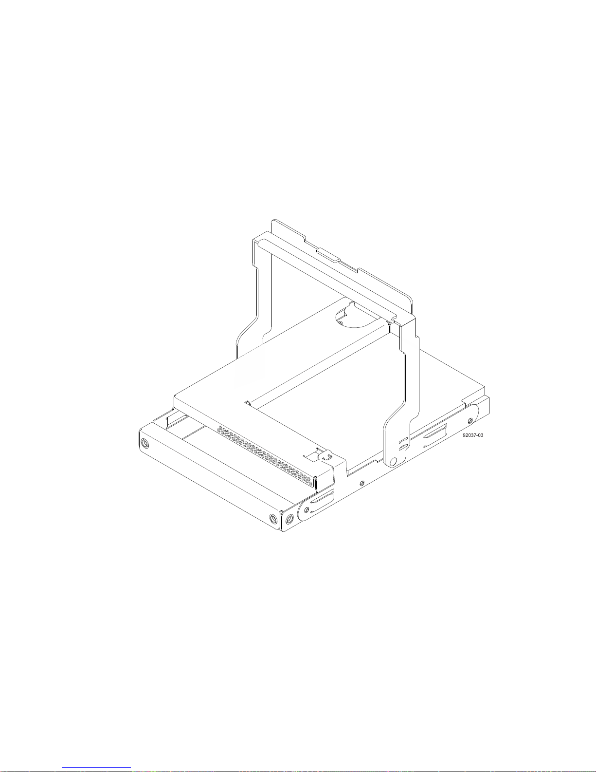
Starting with the first drive, raise the drive handle to the vertical position.
3.
4. Align the two raised buttons on the drive with the notches on the drawer.
5. Starting with the leftmost slot at the front, align the two raised buttons on the drive with the
notches on the drawer. Then, pressing gently on the top of the drive, rotate the drive handle down
until the drive snaps into place.
Page 52
52 | E2700 Controller-Drive Tray and Related Drive Trays Installation Guide
Repeat Step
6.
Slide the drawer back into the drive tray by pushing it from the center and closing both levers.
7.
Attention: Risk of equipment malfunction – Make sure to completely close the drive drawer
by pushing both levers. You must completely close the drive drawer to allow proper airflow and
prevent overheating.
8. Attach the bezel to the front of the drive tray.
3
through Step 5 to install all of the drives.
Procedure - Removing drives from a 60-drive tray
If you need to move or ship a 60-drive controller-drive tray or a 60-drive expansion tray, you must
remove all drives from all drawers.
Step
1. Perform the following steps to remove all of the drives from the drive drawer:
a. Raise the drive handle to vertical.
b. Use the handle to lift the drive from the drive drawer.
Page 53

Step 4 - Installing the controller-drive tray | 53
c. Place the drive in static-free packaging and away from magnetic devices.
Attention: Possible loss of data access – Magnetic fields can destroy all the data on the
drive and cause irreparable damage to the drive circuitry. To avoid loss of data access and
damage to the drives, always keep drives away from magnetic devices.
Page 54
54
Step 5 - Connecting the controller-drive tray to the
hosts
Key terms
Topology
The logical layout of the components of a computer system or network and their interconnections.
Topology deals with questions of what components are directly connected to other components from
the standpoint of being able to communicate. It does not deal with questions of physical location of
components or interconnecting cables. (
Direct topology
A topology that does not use a switch.
Switch or fabric topology
The Dictionary of Storage Networking Terminology
)
A topology that uses a switch.
Things to know - Storage array configuration specifications
for the controller-drive tray
Item
Number of controllers One in a simplex configuration, two in a duplex configuration
Number of host connectors per
controller
Maximum SAS HBA logins
per controller
Maximum Fibre Channel
logins per controller
Maximum iSCSI sessions per
controller
Specification
• Two, four, or six SAS host connectors
• Two SAS and either two or four Fibre Channel host
connectors
• Two SAS and two iSCSI Base-T host connectors
• Two SAS and either two or four iSCSI optical host connectors
128
1024
1024
2048 with a four-port iSCSI optical HIC per controller
Supported Combined Cache
and Processor GB Memory
Sizes per controller
Maximum number of drive
slots supported
Maximum number of hosts per
storage partition
4 or 8
192
256
Page 55
Step 5 - Connecting the controller-drive tray to the hosts | 55
Item Specification
Maximum number of volumes
per storage array
Maximum number of storage
partitions
Maximum number of volumes
per storage partition
Cluster support
512
128
256
• Windows Server 2008 and Windows Server 2012 operating
systems: Windows Hardware Certification Kit (HCK) testing.
• Solaris 10U11 and Solaris 11.1 (x86) operating systems: Sun
Cluster Open Storage Program certification
Things to know - Host channels
Attention: Possible hardware damage – To prevent electrostatic discharge damage to the tray,
use proper antistatic protection when you handle tray components.
• Each controller has two native SAS host ports.
• In addition, you can have additional host ports located on a host interface card (HIC). The
following types of HICs are supported:
◦ Two or Four SAS connectors at 12 Gb/s
◦ Two or Four Fibre Channel connectors at 16 Gb/s
◦ Two iSCSI Base-T connectors at 10 Gb/s
◦ Two or four iSCSI optical host connectors at 10 Gb/s
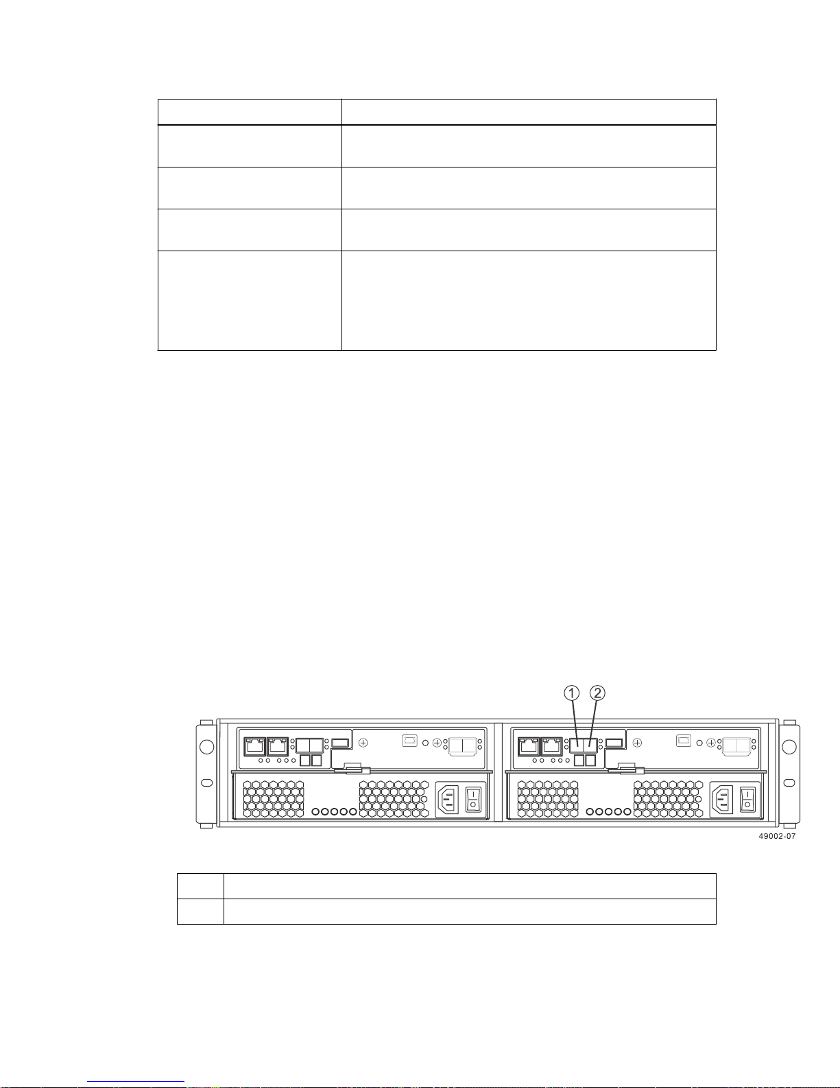
• Host channels on the E2712 and E2724 controllers with no HIC - Rear view
1
2 HD mini-SAS native host channel 2
HD mini-SAS native host channel 1
Page 56
| E2700 Controller-Drive Tray and Related Drive Trays Installation Guide
56
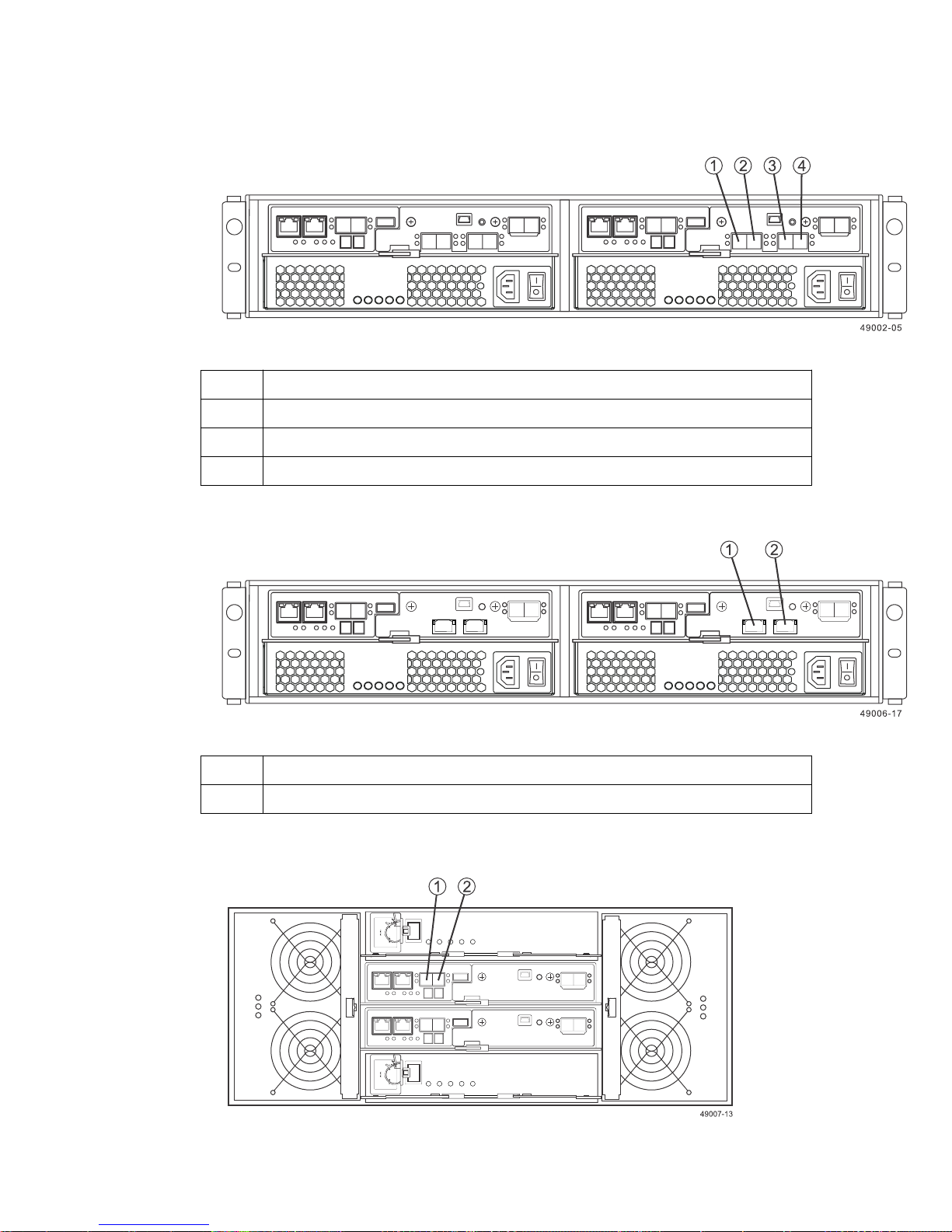
• Host channels on the E2712 and E2724 controllers with a four-port SAS HIC - Rear view
1
HD mini-SAS HIC channel 3
2 HD mini-SAS HIC channel 4
3 HD mini-SAS HIC channel 5
4 HD mini-SAS HIC channel 6
• Host channels on the E2712 and E2724 controllers with a two-port iSCSI HIC - Rear view
1
HD mini-SAS HIC channel 3
2 HD mini-SAS HIC channel 4
• Host channels on the E2760 controller with no HIC - Rear view
Page 57
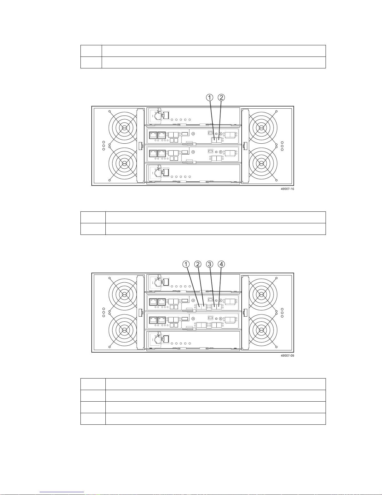
Step 5 - Connecting the controller-drive tray to the hosts | 57
1 HD mini-SAS native host channel 1
2 HD mini-SAS native host channel 2
• Host channels on the E2760 controller with a two-port SAS HIC - Rear view
1
HD mini-SAS HIC channel 3
2 HD mini-SAS HIC channel 4
• Host channels on the E2760 controller with a four-port SAS HIC - Rear view
1
HD mini-SAS HIC channel 3
2 HD mini-SAS HIC channel 4
3 HD mini-SAS HIC channel 5
4 HD mini-SAS HIC channel 6
Page 58
| E2700 Controller-Drive Tray and Related Drive Trays Installation Guide
58
Procedure - Connecting host cables on a controller-drive
tray
About this task
Important: Ensure that you have installed the host bus adapters (HBAs). See
host bus adapters for the controller-drive tray
install the HBA and how to use the supplied configuration utilities.
The type of HICs (SAS, iSCSI, or Fibre Channel) must match the type of the HBAs or match the
type of switch interface to which you connect them.
See the examples in the following section for example cabling patterns.
Steps
Perform one of the following actions:
1.
• If your configuration contains either a Fibre Channel host interface card or an iSCSI host
interface card and uses optical cables, start with the first host channel of each controller, and
plug one end of the cable into the SFP transceiver in the host channel, go to step
61.
• If your configuration contains a SAS host interface card or uses copper cables, go to step 2 on
page 61.
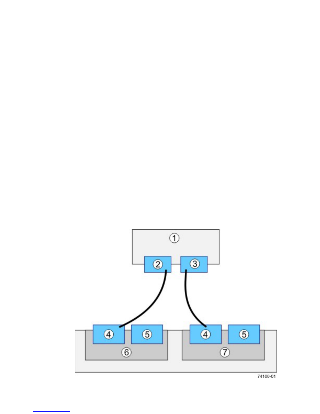
The following four figures show valid host-to-controller-drive tray configurations.
• Direct topology – One host and a dual controller-drive tray
on page 31 for additional information about how to
Step 3 - Installing the
3
on page
Page 59
Step 5 - Connecting the controller-drive tray to the hosts | 59
1 Host
2 HBA 1
3 HBA 2
4 Host port 1
5 Host port 2
8 Controller A
9 Controller B
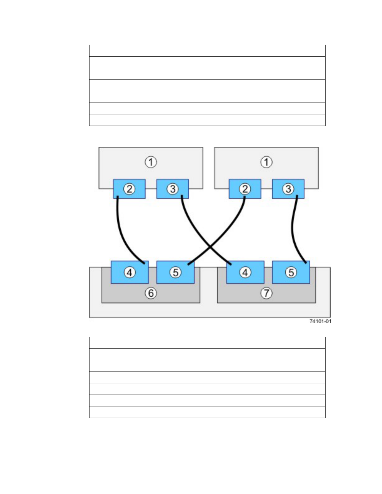
•
Direct topology – Two hosts and a dual controller-drive tray for maximum redundancy
1
2 HBA 1
3 HBA 2
4 Host port 1
5 Host port 2
8 Controller A
9 Controller B
Hosts
Page 60
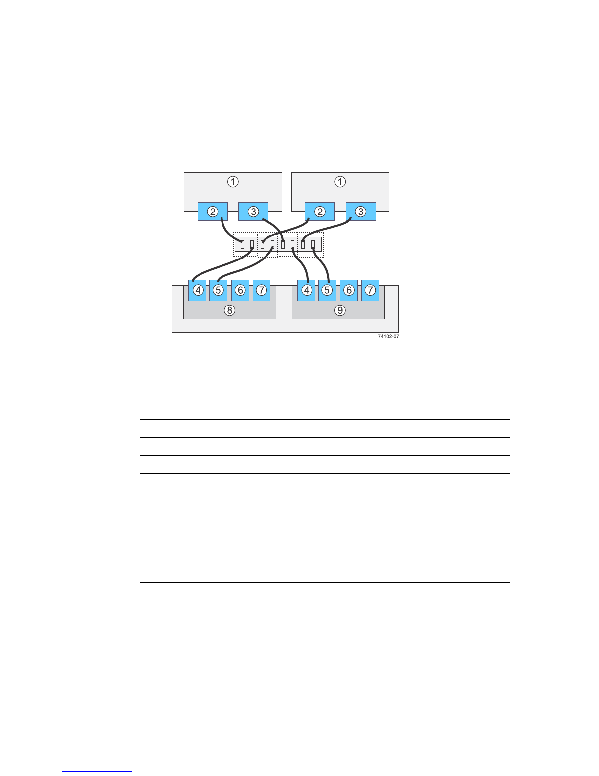
60 | E2700 Controller-Drive Tray and Related Drive Trays Installation Guide
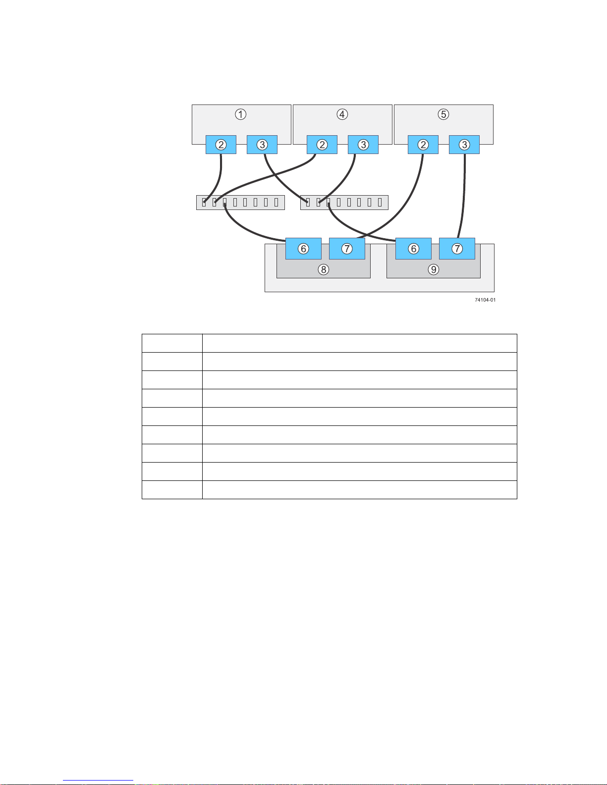
• Switch or fabric topology - Two hosts and a dual controller-drive tray with a four-port
connection and a zoned switch
1
Hosts
2 HBA 1 or NIC 1
3 HBA 2 or NIC 2
4 Host port 1
5 Host port 2
6 Host port 3
7 Host port 4
8 Controller A
9 Controller B
Page 61
Step 5 - Connecting the controller-drive tray to the hosts |
• Mixed topology - Three hosts and a dual controller-drive tray
61
1
Hosts
2 HBA 1 or NIC 1
3 HBA 2 or NIC 2
4 Host 2
5 Host 3
6 Host port 1
7 Host port 2
8 Controller A
9 Controller B
2. Plug either end of the host interface cable into the controller.
3. Plug the other end of the cable into an HBA in the host (direct topology) or into a switch (fabric
topology).
4. Affix a label to each end of the cable with this information. A label is very important if you need
to disconnect cables to service a controller. Include this information on the labels:
• The host name and the HBA port (for direct topology)
• The switch name and the port (for fabric topology)
• The controller ID (for example, controller A )
• The host channel ID (for example, host channel 1)
Example label abbreviation – Assume that a cable is connected between port 1 in HBA 1 of a
host named Engineering and host channel 1 of controller A. A label abbreviation can be as
follows.
Page 62

62 | E2700 Controller-Drive Tray and Related Drive Trays Installation Guide
5. Repeat these steps for each controller and host channel that you intend to use.
Page 63

63
Step 6 - Installing the drive trays for the controllerdrive tray configurations
Things to know - General installation of drive trays
Note: If you are installing the drive tray in a cabinet with other trays, ensure that the combined
power requirements of the drive tray and the other trays do not exceed the power capacity of your
cabinet.
If you are performing a hot add of a tray to an existing storage array, refer to the
Guide
.
• Special site preparation is not required for any of these drive trays beyond what is normally found
in a computer lab environment.
• The power supplies meet standard voltage requirements for both domestic and worldwide
operation.
• Keep as much weight as possible in the bottom half of the cabinet.
Refer to the
Site Preparation Guide
for important considerations about cabinet installation.
Hardware Cabling
Procedure - Installing the DE1600 and DE5600 drive trays
About this task
Warning: (W08) Risk of bodily injury – Two persons are required to safely lift the component.
Warning: (W05) Risk of bodily injury – If the bottom half of the cabinet is empty, do not install
components in the top half of the cabinet. If the top half of the cabinet is too heavy for the bottom
half, the cabinet might fall and cause bodily injury. Always install a component in the lowest
available position in the cabinet.
You can install the drive tray into an industry-standard cabinet.
This procedure describes how to install the mounting rails into an industry-standard cabinet.
Attention: Possible hardware damage – To prevent electrostatic discharge damage to the tray,
use proper antistatic protection when handling tray components.
Steps
1. Ensure that the cabinet is in the final location and that you meet the clearance requirements as
shown.
• DE1600 drive tray – Airflow and clearance requirements
Page 64
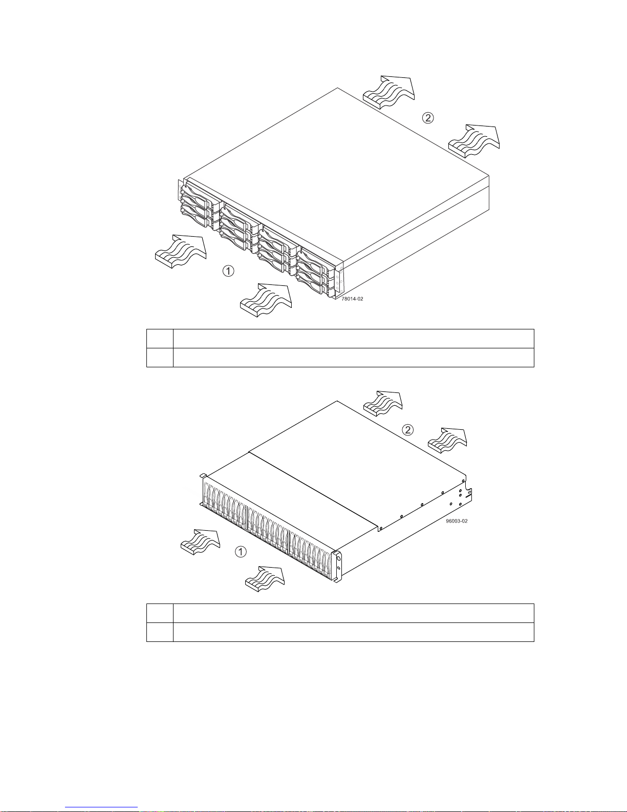
| E2700 Controller-Drive Tray and Related Drive Trays Installation Guide
64
1 76 cm (30 in.) clearance in front of the cabinet
2 61 cm (24 in.) clearance behind the cabinet
• DE5600 drive tray – Airflow and clearance requirements
1
76 cm (30 in.) clearance in front of the cabinet
2 61 cm (24 in.) clearance behind the cabinet
Note: Fans pull air through the tray from front to back across the drives.
2. Lower the feet on the cabinet to keep the cabinet from moving.
3. Remove the drive tray and all contents from the shipping carton.
4. Position the mounting rails in the cabinet, as follows: For more information, refer to the
installation instructions that are included with your mounting rails.
• If you are installing the mounting rails above an existing tray, position the mounting rails
directly above the tray.
Page 65
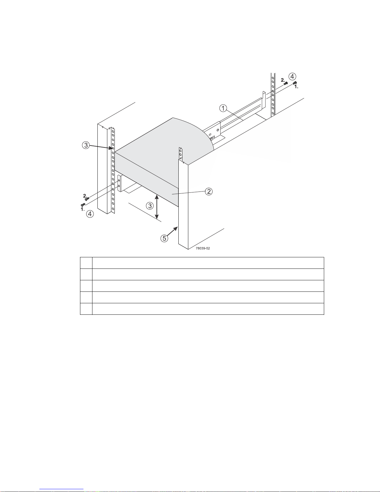
Step 6 - Installing the drive trays for the controller-drive tray configurations | 65
• If you are installing the mounting rails below an existing tray, allow either 8.7-cm (3.4-in.)
vertical clearance for the DE1600 drive tray or 8.8-cm (3.5-in.) vertical clearance for the
DE5600 drive tray.
1 Mounting rail
2 Existing tray
3 Clearance above and below the existing tray
4 Screws for securing the mounting rail to the cabinet (front and rear)
5 Industry-standard cabinet
5. Attach the mounting rails to the cabinet.
a. Ensure that the adjustment screws on the mounting rail are loose so that the mounting rail can
extend or contract as needed.
Page 66
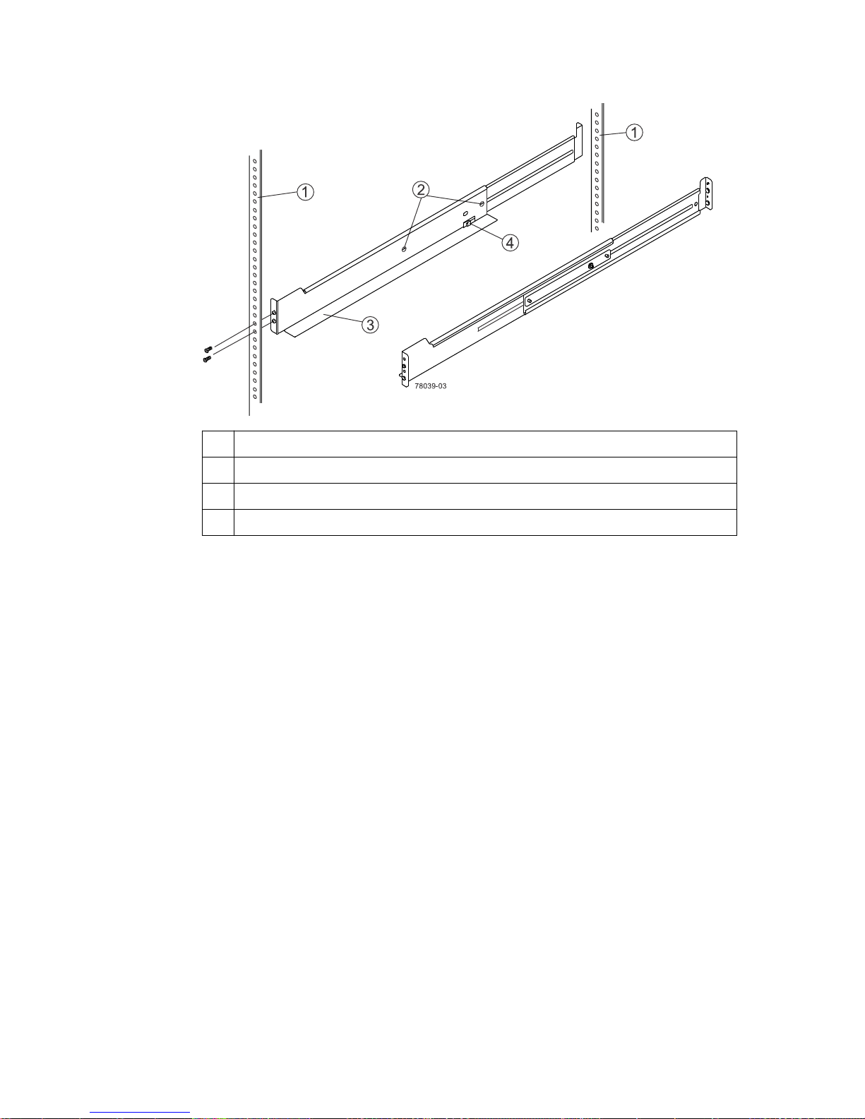
66 | E2700 Controller-Drive Tray and Related Drive Trays Installation Guide
1 Cabinet mounting holes
2 Adjustment screws for locking the mounting rail length
3 Mounting rails
4 Clip for securing the rear of the drive tray
b. Place the mounting rail inside the cabinet, and extend the mounting rail until the flanges on
the mounting rail touch the inside of the cabinet.
c. Ensure that the alignment spacers on the front flange of the mounting rail fit into the mounting
holes in the cabinet.
The front flange of each mounting rail has two alignment spacers. The alignment spacers are
designed to fit into the mounting holes in the cabinet. The alignment spacers help position and
hold the mounting rail.
Note: If the cabinet in which you are installing this tray has square holes, there are larger
spacers that can be used to mount the rail.
Page 67
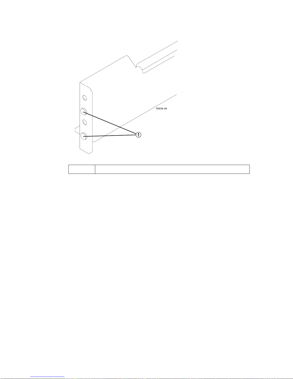
Step 6 - Installing the drive trays for the controller-drive tray configurations | 67
1 Alignment spacers
d. Insert one M5 screw through the front of the cabinet and into the top captured nut in the
mounting rail. Tighten the screw.
e. Insert two M5 screws through the rear of the cabinet and into the captured nuts in the rear
flange in the mounting rail. Tighten the screws.
f. Tighten the adjustment screws on the mounting rail.
g. Repeat these steps to install the second mounting rail.
6. With the help of one other person, slide the rear of the drive tray onto the mounting rails. The rear
edge of the drive tray must fit into the clip on the mounting rail.
The drive tray is correctly aligned when these conditions are met:
• The mounting holes on the front flanges of the drive tray align with the mounting holes on the
front of the mounting rails. See item 4 in the following figure.
• The rear edge of the drive tray sheet metal fits into the clip on the mounting rail.
• The holes in the drive tray sheet metal for the rear hold-down screws align with the captured
nuts in the side of the mounting rails.
Page 68
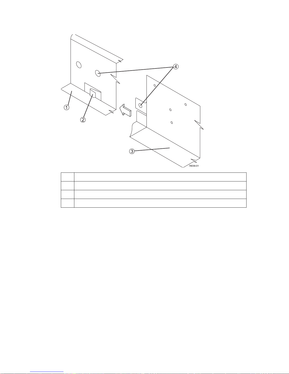
68 | E2700 Controller-Drive Tray and Related Drive Trays Installation Guide
1 Mounting rail
2 Clip
3 Partial view of the drive tray rear sheet metal
4 Mounting holes
7. Secure the front of the drive tray to the cabinet. Use the two screws to attach the flange on each
side of the front of the drive tray to the mounting rails.
a. Insert one M5 screw through the bottom hole of a flange on the drive tray so that the screw
goes through the cabinet rail and engages the bottom captured nut in the mounting rail.
Tighten the screw.
b. Repeat this step for the second flange.
• DE1600 drive tray
Page 69
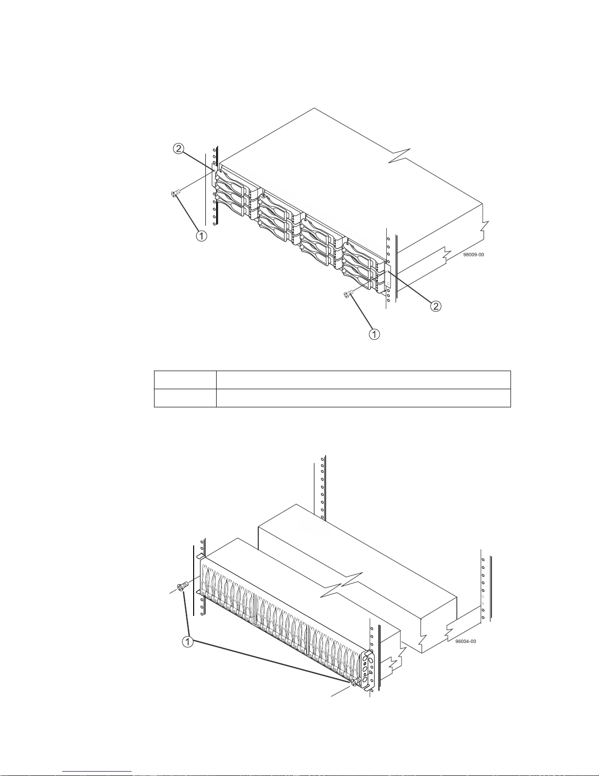
Step 6 - Installing the drive trays for the controller-drive tray configurations | 69
1 Screw
2 Mounting hole
• DE5600 drive tray
Page 70
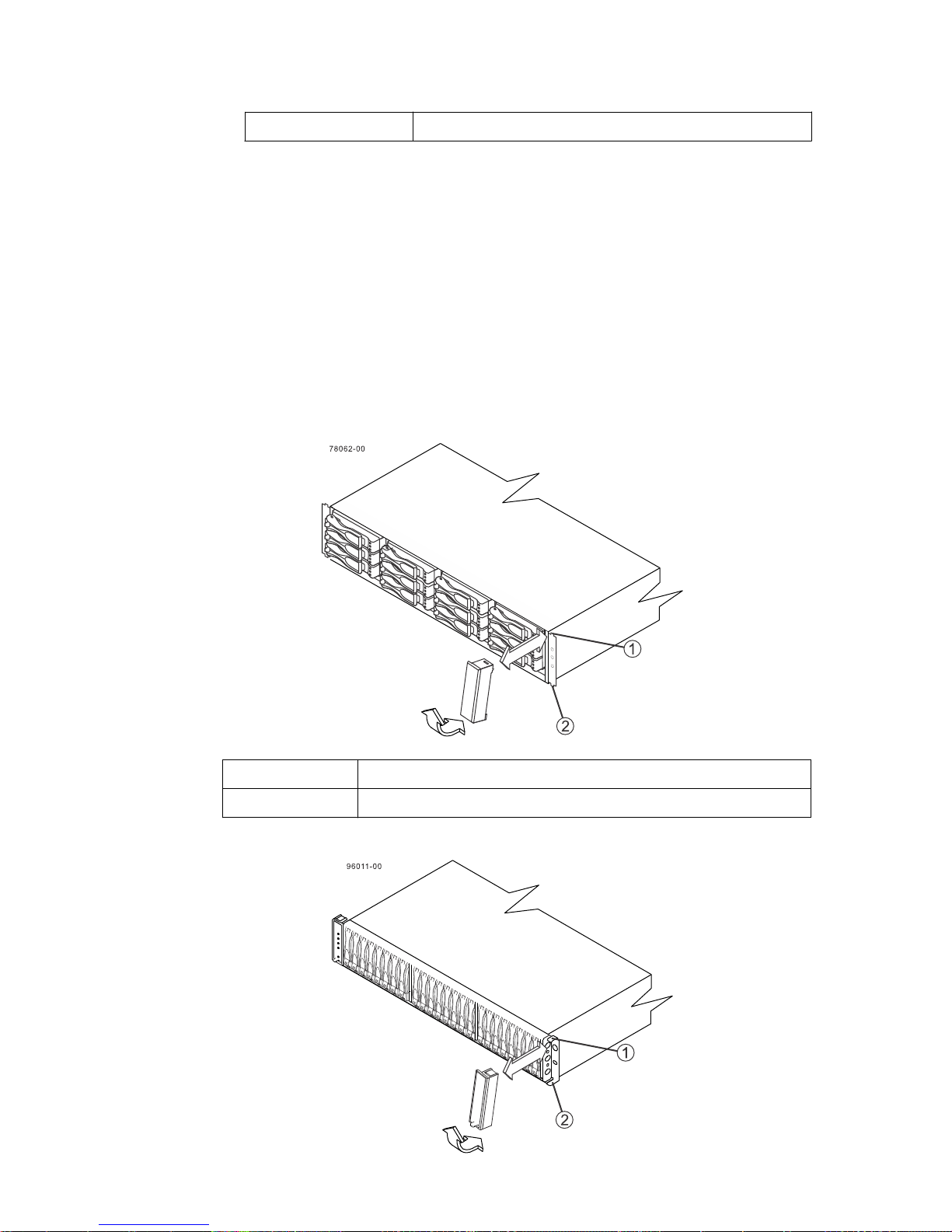
70 | E2700 Controller-Drive Tray and Related Drive Trays Installation Guide
1 Screw
Note: The rear end contains two controllers. The top of the is the side with the labels.
8. Secure the side of the drive tray to the mounting rails by performing these steps:
a. Insert one M4 screw through the side sheet metal of the drive tray into the captured nut on the
side of the mounting rail. Tighten the screw.
b. Repeat this step for the other side.
Attach the plastic end caps onto the front of the drive tray.
9.
a. Put the top of the end cap on the hinge tab that is part of the drive tray mounting flange.
b. Gently press on the bottom of the end cap until it snaps into place over the retainer on the
bottom of the drive tray mounting flange.
•
Attaching the end caps to the DE1600 drive tray
1
2 Retainer
• Attaching the end caps to the DE5600 drive tray
Hinge tab
Page 71
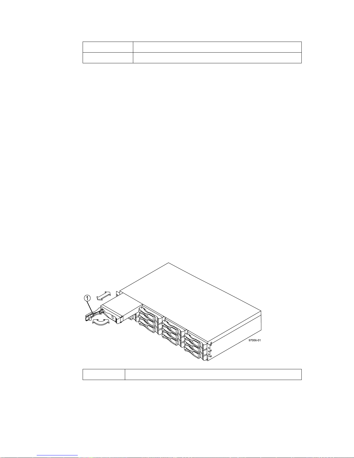
Step 6 - Installing the drive trays for the controller-drive tray configurations |
1 Hinge tab
2 Retainer
Procedure - Installing drives in the DE1600 and DE5600
drive trays
About this task
In some situations, the drive tray might be delivered without the drives installed. Follow the steps in
this procedure to install the drives.
Attention: Risk of equipment malfunction – To avoid exceeding the functional and
environmental limits, install only drives that have been provided or approved by NetApp. Drives
might be shipped but not installed. System integrators, resellers, system administrators, or users
can install the drives.
Note: For the DE1600 drive tray, the installation order of the drives is from top to bottom and from
left to right. For the DE5600 drive tray, the installation order is from left to right. The installation
order is important because the drives might already contain configuration information that depends
upon the correct sequence of the drives in the tray.
71
Steps
1. Beginning with the first drive slot (the upper-left slot of the DE1600 drive tray or the left slot of
the DE5600 drive tray), place the drive in the slot guides, and slide the drive all the way into the
slot.
2. Push the drive handle to the right (DE1600 drive tray) or down (DE5600 drive tray).
• Installing a drive in the DE1600 drive tray
1
Drive handle
• Installing a drive in the DE5600 drive tray
Page 72
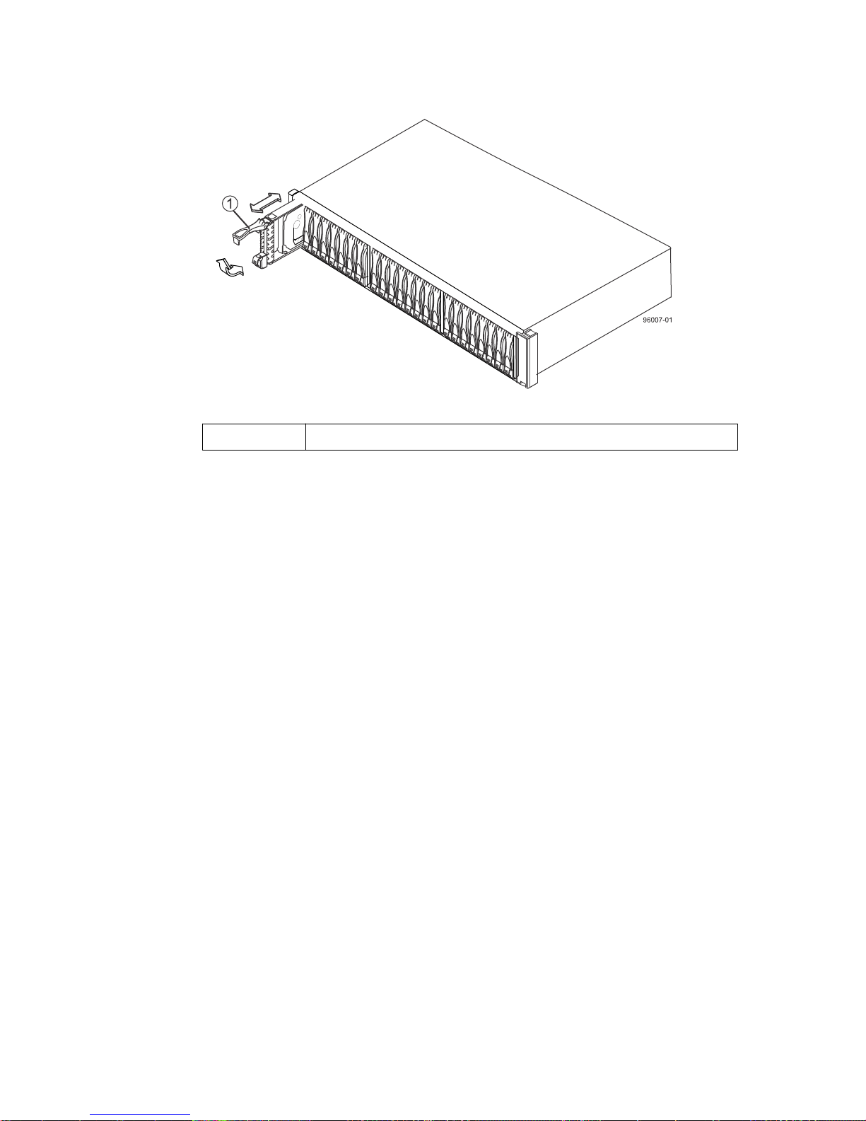
| E2700 Controller-Drive Tray and Related Drive Trays Installation Guide
72
1 Drive handle
Note: In some applications, the drive handle might have the hinge on the right.
3. For the DE1600 drive tray, install the second drive beneath the first drive. For the DE5600 drive
tray, install the second drive to the right of the first drive.
4. For the DE1600 drive tray, install the other drives from top to bottom and then from left to right.
For the DE5600 drive tray, install the other drives to the right.
Procedure - Installing the DE6600 drive tray
About this task
Warning: (W10) Risk of bodily injury – Four or more persons are required to safely lift the
component.
Attention: Risk of equipment malfunction – To avoid possible equipment damage and ensure
safe and efficient servicing of the equipment, install DE6600 drive trays towards the bottom of a
cabinet.
Warning: (W05) Risk of bodily injury – If the bottom half of the cabinet is empty, do not install
components in the top half of the cabinet. If the top half of the cabinet is too heavy for the bottom
half, the cabinet might fall and cause bodily injury. Always install a component in the lowest
available position in the cabinet.
You can install the high-density, 6-Gb SAS SBB 2.0-compliant DE6600 drive tray into an industrystandard cabinet, provided it has a depth of 100 cm (40 in.). A minimum depth of 76 cm (30 in.)
between the front EIA support rails and the rear EIA support rails is required.
This procedure describes how to install the mounting rails into an industry-standard cabinet.
Attention: Possible hardware damage – To prevent electrostatic discharge damage to the tray,
use proper antistatic protection when handling tray components.
Page 73
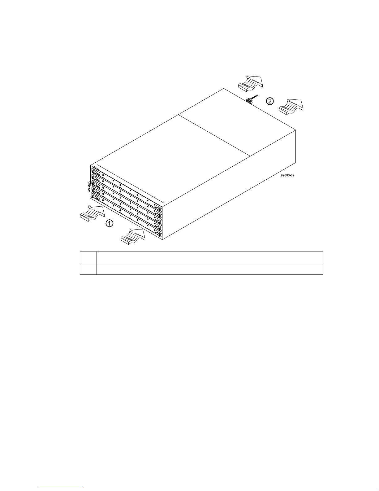
Step 6 - Installing the drive trays for the controller-drive tray configurations | 73
Steps
1. Make sure that the cabinet is in the final location. Make sure that you meet the airflow and
clearance requirements shown in the following figure.
1 91 cm (36 in.) clearance in front of the cabinet
2 61 cm (24 in.) clearance behind the cabinet
Note: Fans pull air through the drive tray from front to back across the drives.
2. Lower the feet on the cabinet to keep the cabinet from moving.
3. Before removing the drive tray and all of the contents from the shipping carton, locate the tray
handles and attach them to the drive tray.
a. Align the handle just under the thumb latch.
b. Push the handle up until it clicks in place with the thumb latch.
Page 74
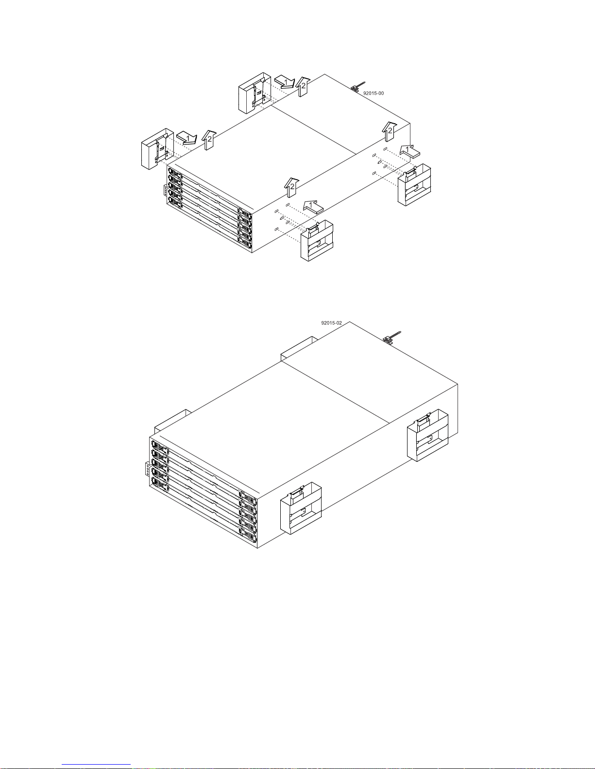
| E2700 Controller-Drive Tray and Related Drive Trays Installation Guide
74
With the help of at least three other persons, remove the drive tray and all of the contents from the
4.
shipping carton, using the four drive tray handles (two to a side) as shown in the following figure.
Set the drive tray aside.
5. Position the mounting rails in the cabinet.
• If you are installing the mounting rails above an existing tray, position the mounting rails
directly above the tray.
• If you are installing the mounting rails below an existing tray, allow 17.8 cm (7 in.) vertical
clearance for a DE6600 drive tray.
Page 75
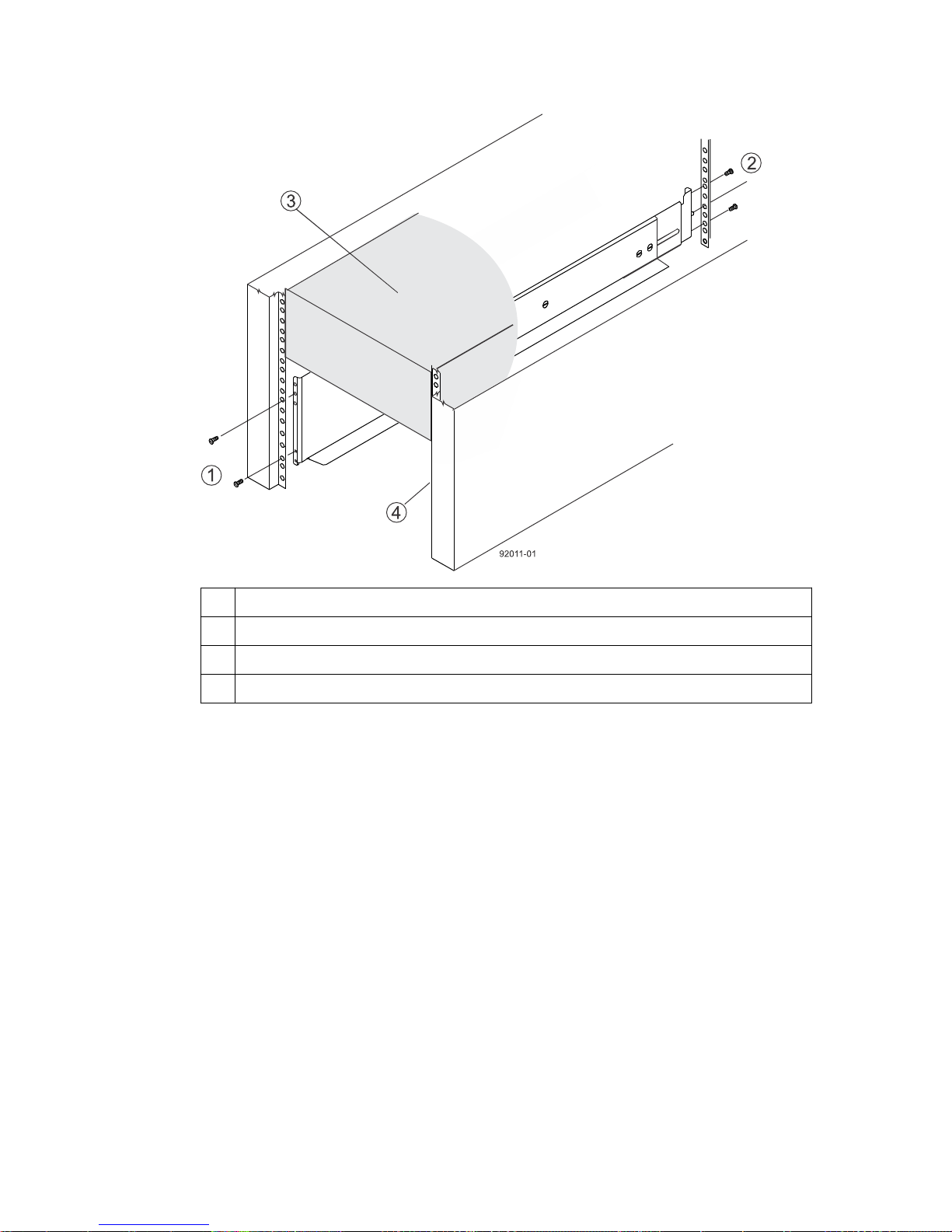
Step 6 - Installing the drive trays for the controller-drive tray configurations | 75
1 Screws for securing the mounting rail to the cabinet (front)
2 Screws for securing the mounting rail to the cabinet (rear)
3 Existing tray
4 Industry-standard cabinet
6. To attach the mounting rails to the cabinet, do one of the following:
• If you are using the long fixed-size mounting rails, go to step 7.
• If you are using the shorter adjustable mounting rails, go to step 8.
7. Attach the long fixed-size mounting rails to the cabinet.
a. Make sure that the adjustment screws on the mounting rail are loose so that the mounting rail
can extend or contract as needed.
Page 76
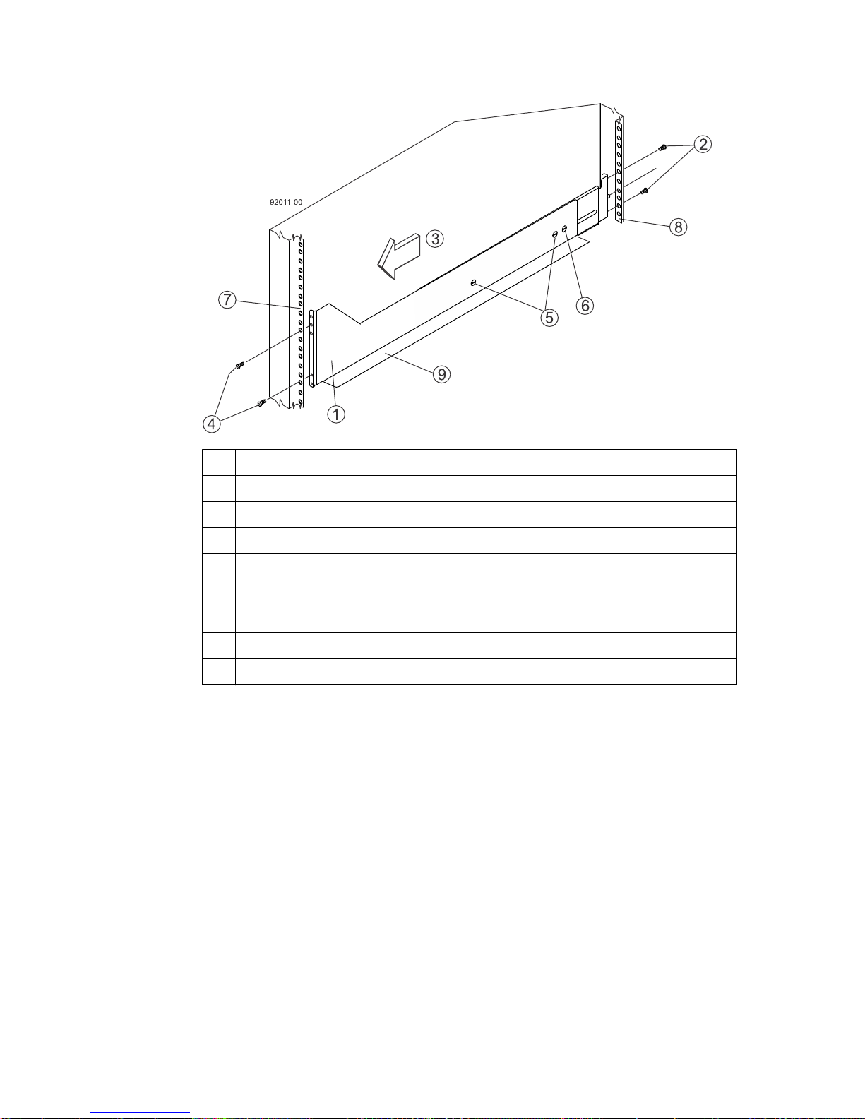
| E2700 Controller-Drive Tray and Related Drive Trays Installation Guide
76
1 Front of the mounting rail
2 Two M5 screws for the rear EIA support rail
3 Front of the cabinet
4 Two M5 screws for the front EIA support rail
5 Adjustment screws
6 Rear hold-down screw
7 Cabinet mounting holes on the front EIA support rail
8 Cabinet mounting holes on the rear EIA support rail
9 Mounting rail lip
b. Remove the rear hold-down screw. It protrudes from the inside of the rail and prevents you
from sliding the drive tray onto the rails.
c. Place the mounting rail inside the cabinet, and extend the mounting rail until the flanges on
the mounting rail touch the inside of the cabinet.
Note: If you are mounting the DE6600 drive tray in a cabinet with square holes, use the
square hole-to-round hold adapters in the rail kit to align the screws in the holes. The square
hole-to-round hold adapters are round washers with shallow shoulders that fit snugly into
the square holes in the rack.
d. Insert one M5 screw through the front of the cabinet, and screw it into the top captured nut in
the mounting rail.
e. Insert two M5 screws through the rear of the cabinet, and screw them into the captured nuts in
the rear flange in the mounting rail.
f. Counting up from the bottom of the mounting rail, place the bottom of the rear bracket in the
8th hole of the cabinet, so that the top of the rear bracket is in the 11th hole. The distance
between the two holes should be 1U or 4.45 cm (1.75 in).
g. Tighten the adjustment screws on the mounting rail.
h. Repeat these steps to install the second mounting rail.
Page 77
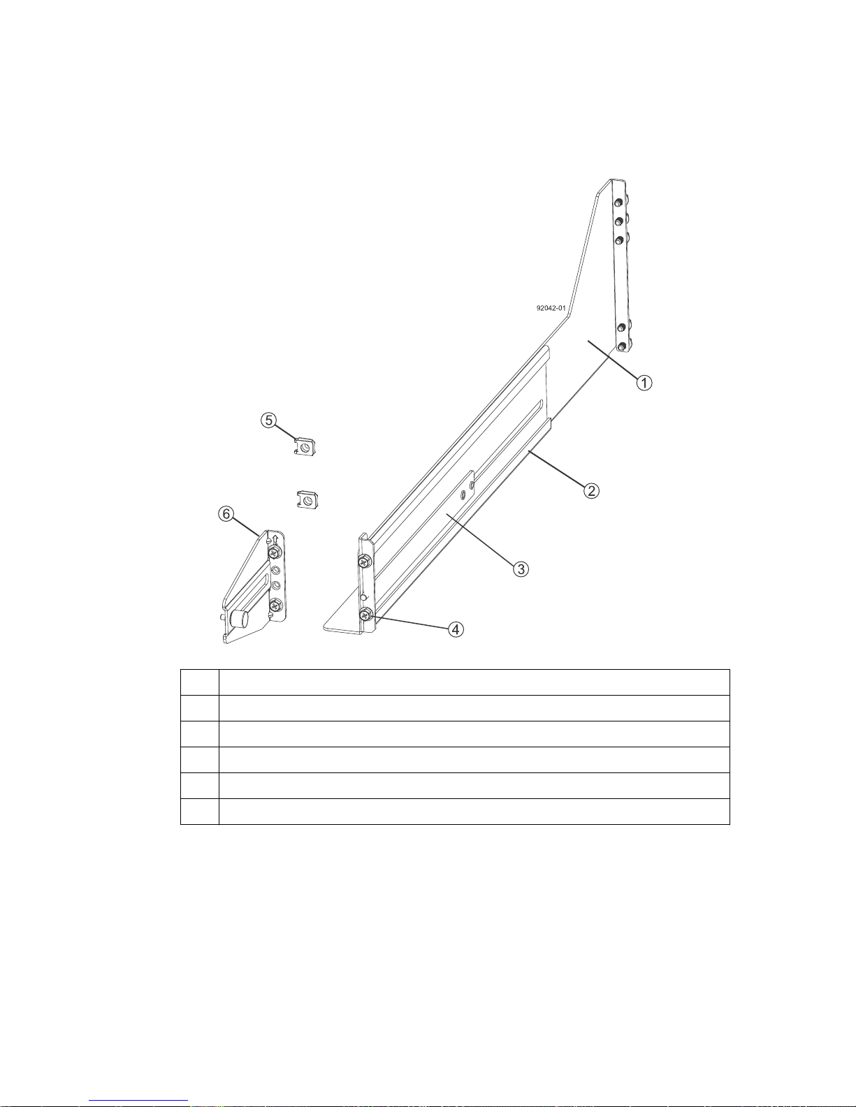
Step 6 - Installing the drive trays for the controller-drive tray configurations |
i. Insert one M5 screw through the front of the mounting rail. You use this screw to attach the
drive tray to the cabinet.
8. Attach the shorter, adjustable size mounting rails to the cabinet.
77
1 Front of the mounting rail
2 Rear of the mounting rail
3 Rail fix bar
4 Two M5 screws for the front EIA support rail
5 Two clips for the front EIA support rail
6 Rear bracket
a. Make sure that the adjustment screws on the mounting rail are loose so that the mounting rail
can extend or contract as needed. The adjustment screws are on the other side of the previous
figure.
b. Place the mounting rail inside the cabinet, and extend the mounting rail until the flanges on
the mounting rail touch the inside of the cabinet.
c. Insert one M5 screw through the front of the cabinet, and screw it into the top captured nut in
the mounting rail.
Page 78
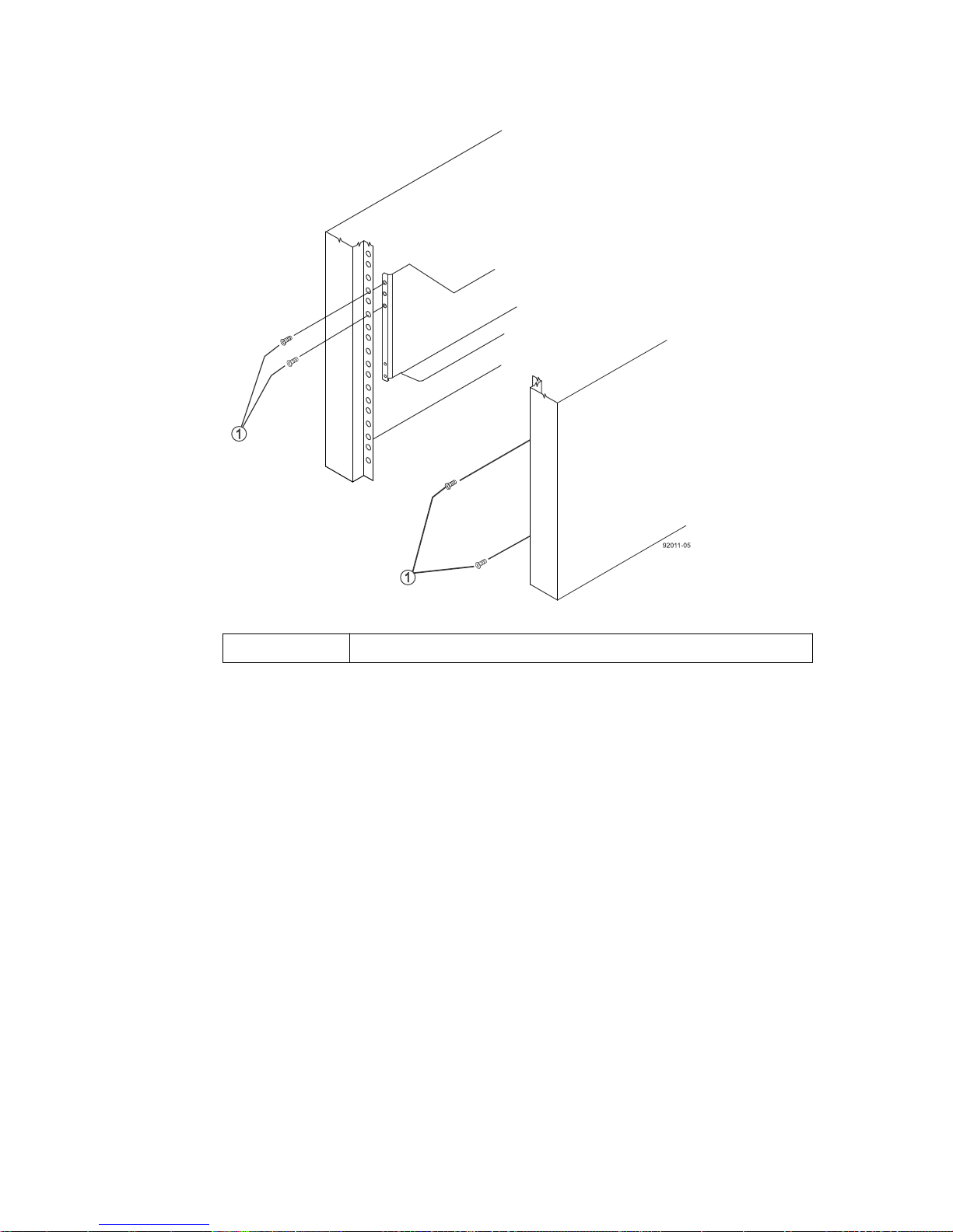
78 | E2700 Controller-Drive Tray and Related Drive Trays Installation Guide
1 M5 screws
d. Insert two M5 screws through the rear of the cabinet, and screw them into the captured nuts in
the rear flange in the mounting rail.
e. Counting up from the bottom of the mounting rail, place the bottom of the rear bracket in the
8th hole of the cabinet, so that the top of the rear bracket is in the 11th hole. The distance
between the two holes should be 1U or 4.45 cm (1.75 in).
f. Tighten the adjustment screws on the mounting rail.
g. Repeat these steps to install the second mounting rail.
Page 79
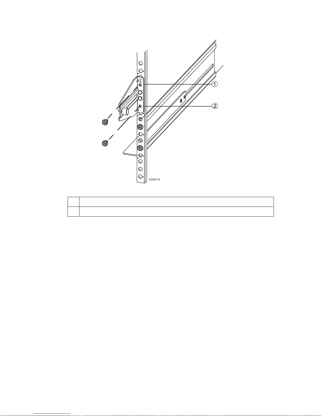
Step 6 - Installing the drive trays for the controller-drive tray configurations | 79
1 Top cabinet mounting hole on the rear EIA support rail
2 Bottom cabinet mounting hole on the rear EIA support rail
9. Remove the bezel from the front of the drive tray.
10. With the help of at least three other persons, slide the rear of the drive tray onto the mounting
rails. The drive tray is correctly aligned when the mounting holes on the front flanges of the drive
tray align with the mounting holes on the front of the mounting rails.
Warning: (W10) Risk of bodily injury – Four or more persons are required to safely lift the
component.
11. After the controller-drive tray is correctly aligned, remove the enclosure lift handles as shown in
the following figure:
a. Use your thumb to unlatch and remove the rear enclosure lift handles (two to a side).
b. Use the front enclosure lift handles to slide the drive tray all the way into the cabinet.
c. After the drive tray is secure in the cabinet, use your thumb to unlatch and remove the front
enclosure lift handles (two to a side).
Page 80
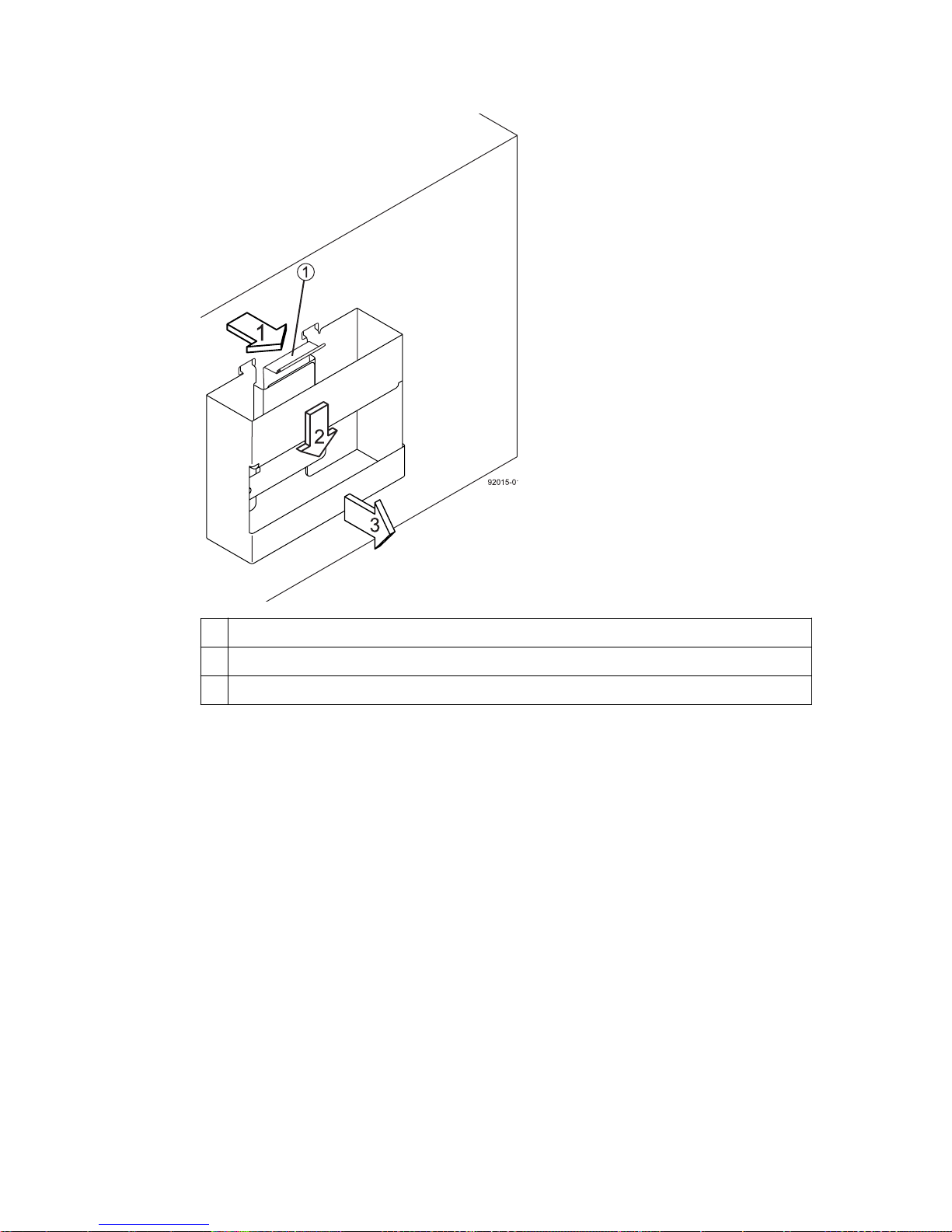
| E2700 Controller-Drive Tray and Related Drive Trays Installation Guide
80
1 Pull the thumb latch away from the controller-drive tray to detach the hook.
2 Shift the handle down to release the other four hooks.
3 Move the handle away from the controller-drive tray.
12. Secure the front of the drive tray to the cabinet. Use the four screws to attach the flange on each
side of the front of the drive tray to the mounting rails.
a. Insert two M5 screws through the bottom holes of a flange on the drive tray so that the screws
go through the EIA support rail and engage the bottom captured nuts in the mounting rail.
Tighten the screws.
You had attached the second and fourth threaded holes in step 8c.
b. Repeat substep a for the second flange.
13. Secure the side of the drive tray to the mounting rails.
a. Tighten the thumbscrew on the rear mounting bracket that you installed in step 8e to secure
the drive tray to the mounting rails.
b. Repeat substep a for the other side.
Note: Make sure that each drive drawer in the drive tray is securely fastened to ensure proper
air flow to the drives.
Page 81
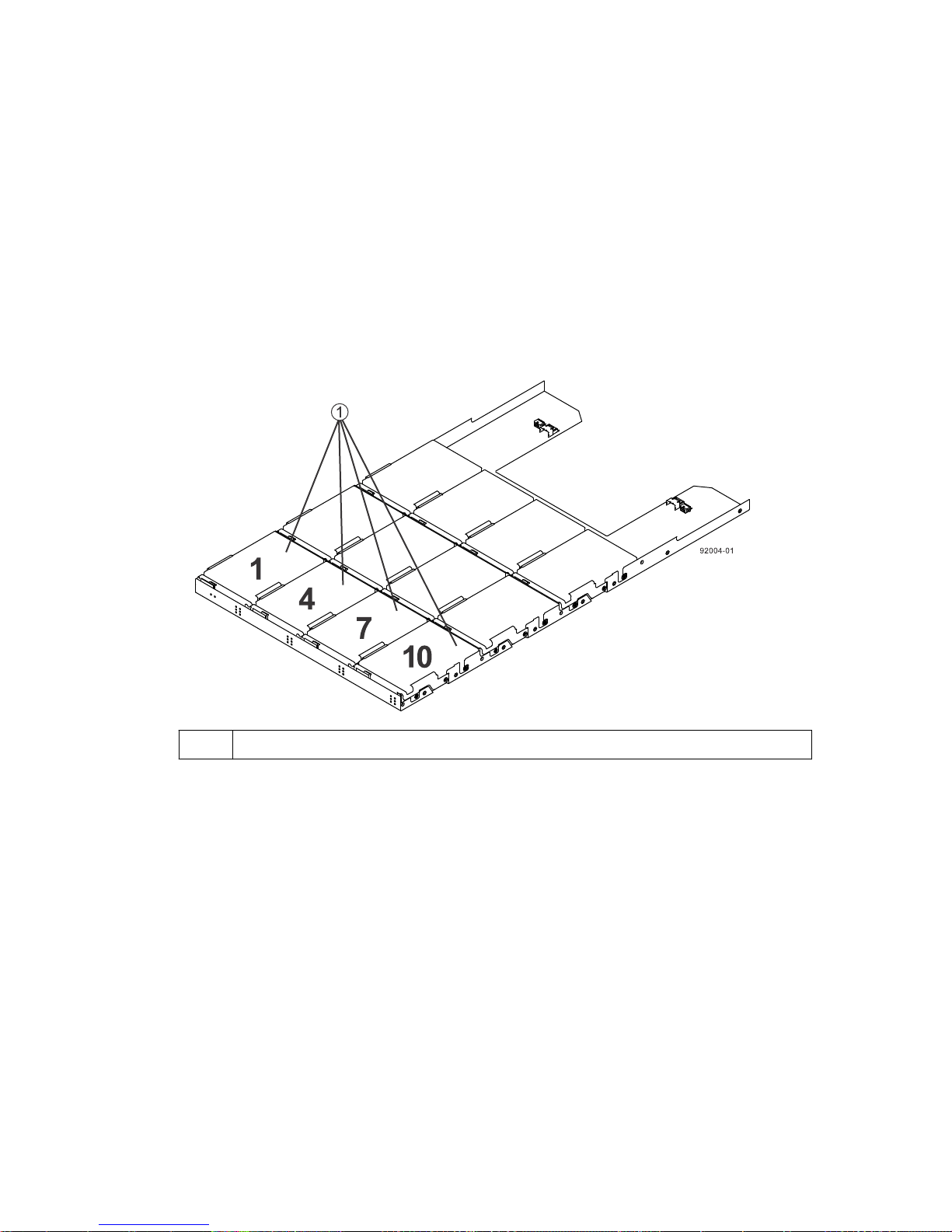
Step 6 - Installing the drive trays for the controller-drive tray configurations |
Procedure - Installing the drives in the DE6600 drive tray
About this task
The DE6600 drive tray is shipped with the drive drawers installed, but the drives are not installed.
Attention: Risk of equipment malfunction – To avoid exceeding the functional and
environmental limits, install only drives that have been provided or approved by NetApp.
Attention: Risk of equipment malfunction – All DE6600 drive trays have a limit of five solid
state drives (SSDs) per drawer. If you exceed this limit for SSDs in a particular drawer, the power
source in the drawer could fail.
81
1
If you are installing fewer than 60 drives, if you have SSDs, or if your drives have different
capacities, do the following:
• Install the drives in the front four slots (shown in the figure as slots 1,4, 7, and 10) of each drawer
• Distribute any remaining drives across the drawers.
• Distribute any SSDs evenly across the drawers.
• Do not install more than five SSDs in each drawer (no more than 25 SSDs in each tray) or else the
Attention: Risk of equipment damage – If you want to move the 60-drive tray to a new location
after installing the drives, you must remove all of the drives from the drive tray following proper
drive-removal procedures. Never ship a 60-drive tray with drives installed. See
Removing drives from a 60-drive tray
drive tray.
Slots requiring drives in each drawer
to maintain adequate airflow for cooling. You must install at least 20 drives in the tray.
You must install an equal number of each type of drive in each drawer to use the Drawer Loss
Protection (DLP) feature in SANtricity software. If you have extra drives, you can install them,
but they will not be used for DLP.
power source in the drawer can fail.
Procedure -
for instructions on how to remove the drives from the 60-
Page 82
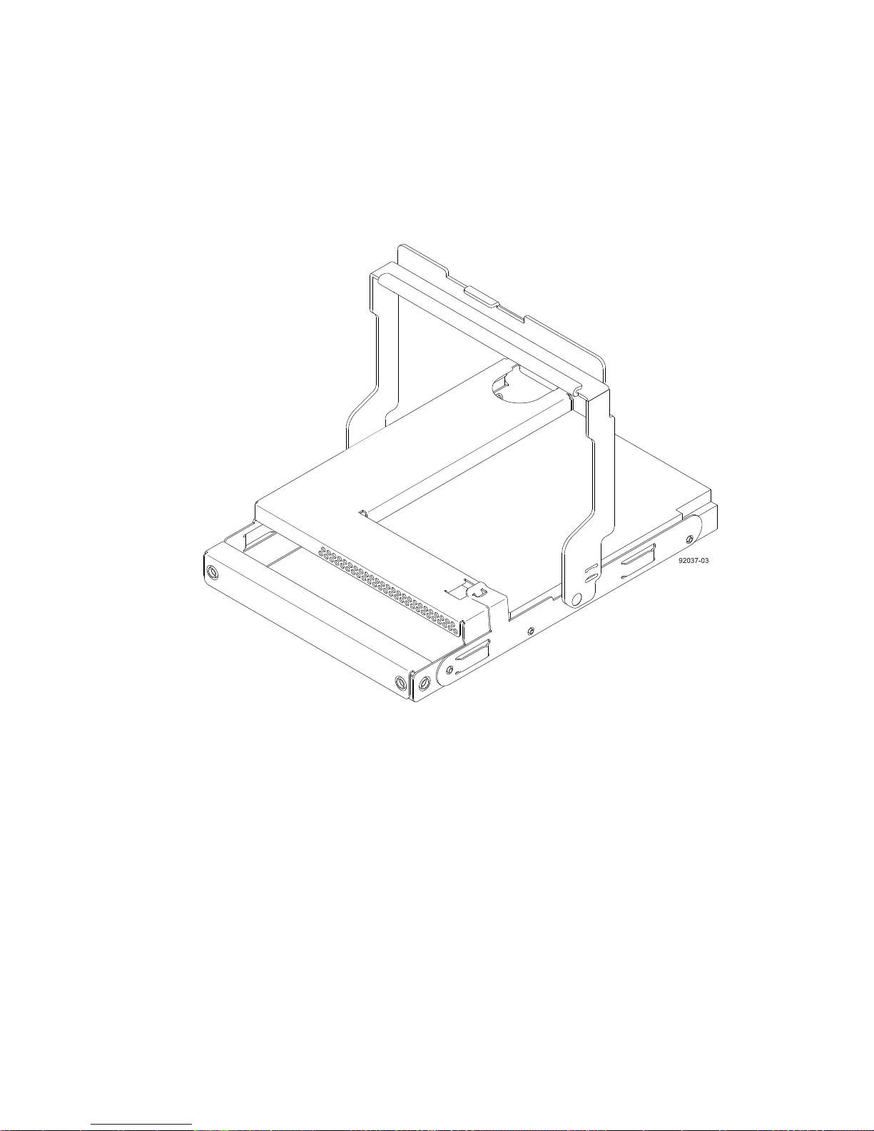
82 | E2700 Controller-Drive Tray and Related Drive Trays Installation Guide
Steps
1. Unlatch the drive drawer by pulling out on both levers at the front of the drawer.
2. Using the extended levers, carefully pull the drive drawer out until it stops. Do not completely
remove the drive drawer from the controller-drive tray.
3. Starting with the first drive, raise the drive handle to the vertical position.
4. Align the two raised buttons on the drive with the notches on the drawer.
5. Starting with the leftmost slot at the front, align the two raised buttons on the drive with the
notches on the drawer. Then, pressing gently on the top of the drive, rotate the drive handle down
until the drive snaps into place.
Page 83
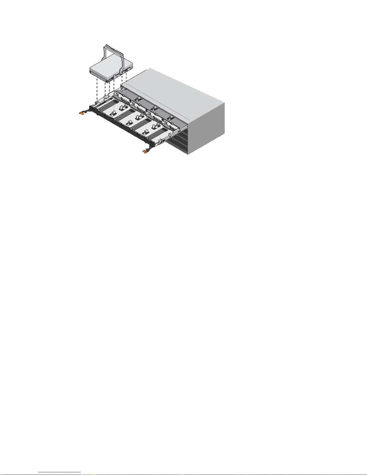
Step 6 - Installing the drive trays for the controller-drive tray configurations |
83
Repeat Step
6.
Slide the drawer back into the drive tray by pushing it from the center and closing both levers.
7.
Attention: Risk of equipment malfunction – Make sure to completely close the drive drawer
by pushing both levers. You must completely close the drive drawer to allow proper airflow and
prevent overheating.
8. Attach the bezel to the front of the drive tray.
3
through Step 5 to install all of the drives.
Things to know - Connecting the power cords
• For each AC power connector on the drive tray, make sure that you use a separate power source in
the cabinet. Connecting to independent power sources maintains power redundancy.
• To ensure proper cooling and ensure availability, the drive tray always uses two power supplies.
• You can use the power cords shipped with the drive tray with typical outlets used in the
destination country, such as a wall receptacle or an uninterrupted power supply (UPS). These
power cords, however, are not intended for use in most EIA-compliant cabinets.
Note: Make sure that you do not turn on the power to the drive tray until this installation guide
instructs you to do so.
Procedure - Connecting the power cords
Steps
1. Make sure that the circuit breakers in the cabinet are turned off.
2. Make sure that both of the power switches on the drive trays are turned off.
3. Connect the primary power cords from the cabinet to the external power source.
Page 84
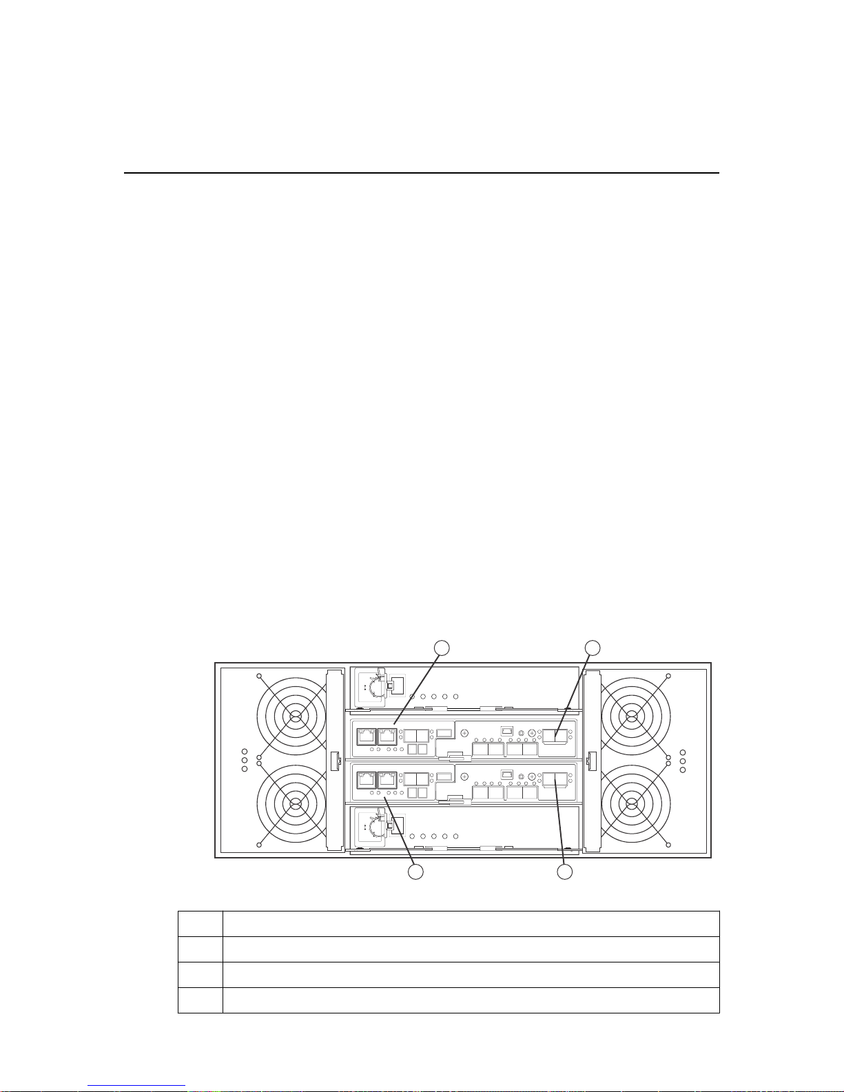
49 0 07 -0 1
1 3
2 4
84
Step 7 - Connecting the controller-drive tray to the
drive trays
Use this step to cable the controller-drive tray and related drive trays. For additional information, see
the
Hardware Cabling Guide
Key terms
Drive channel
The path for the transfer of data between controllers and the drives in the storage array.
Things to know - E2700 controller-drive tray
• The controller-drive trays can connect to the DE1600 drive tray, the DE5600 drive tray, and the
DE6600 drive tray for expansion.
.
• For any one controller-drive tray, you must not exceed the limit of 15 connected drive trays or the
limit for the total number of drive slots in the storage array, which is 192. In a E2760
configuration that consists solely of DE6600 drive trays, only 180 drives are supported. The drive
slot limit includes drive slots in the controller-drive tray.
Note: Ensure that you do not turn on the power to the drive tray until this installation guide
instructs you to do so. For the correct procedure for turning on the power, see
the power and checking for problems in a controller-drive tray configuration
• Drive tray expansion ports on the E2760 controller-drive tray
Step 10 - Turning on
on page 97.
1
2 Controller canister B
3 SAS expansion ports (CH1 and CH2)
4 SAS expansion ports (CH1 and CH2)
• Drive tray expansion ports on the E2712 and E2724 controller-drive trays
Controller canister A
Page 85
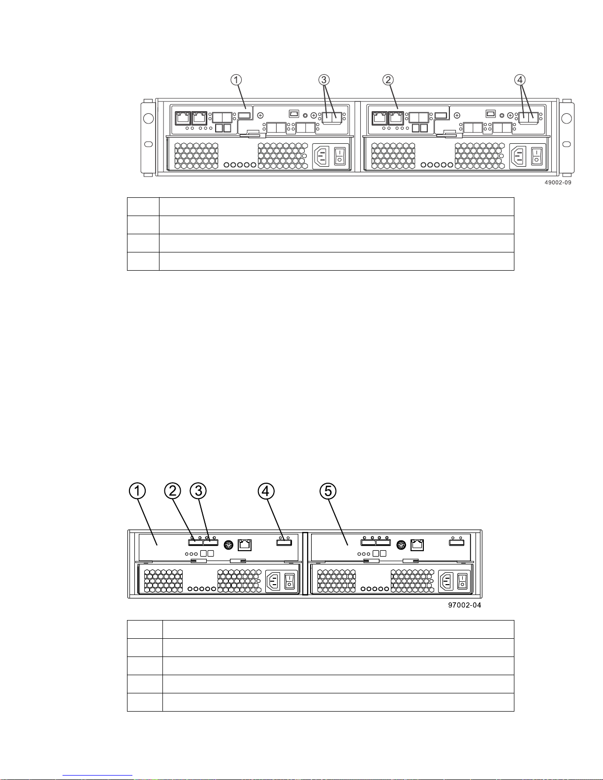
Step 7 - Connecting the controller-drive tray to the drive trays |
1 Controller canister A
2 Controller canister B
3 SAS expansion ports (CH1 and CH2)
4 SAS expansion ports (CH1 and CH2)
Things to know - Drive trays
• Each DE1600 drive tray can contain a maximum of twelve 8.89-cm (3.5-in.) drives.
85
• Each DE5600 drive tray can contain a maximum of twenty-four 6.35-cm (2.5-in.) drives.
• Each DE6600 drive tray can contain a maximum of sixty 8.89-cm (3.5-in.) or 6.35-cm (2.5-in.)
drives.
• Each ESM in the DE1600 drive tray, the DE5600 drive tray, or the DE6600 drive tray contains a
pair of SAS In connectors and one SAS Expansion (Out) connector.
Note: The drive limit might be lower than 192 for some configurations of the E2760 controller-
drive tray. You are notified through the Major Event Log (MEL) if you attempt to install drive slots
in excess of the limit for your storage array. If this occurs, contact technical support .
• DE1600 and DE5600 drive trays - Rear view
1
ESM A
2 SAS IN connector
3 SAS IN connector
4 SAS Expansion (OUT) connector
5 ESM B
• DE6600 drive tray - Rear view
Page 86
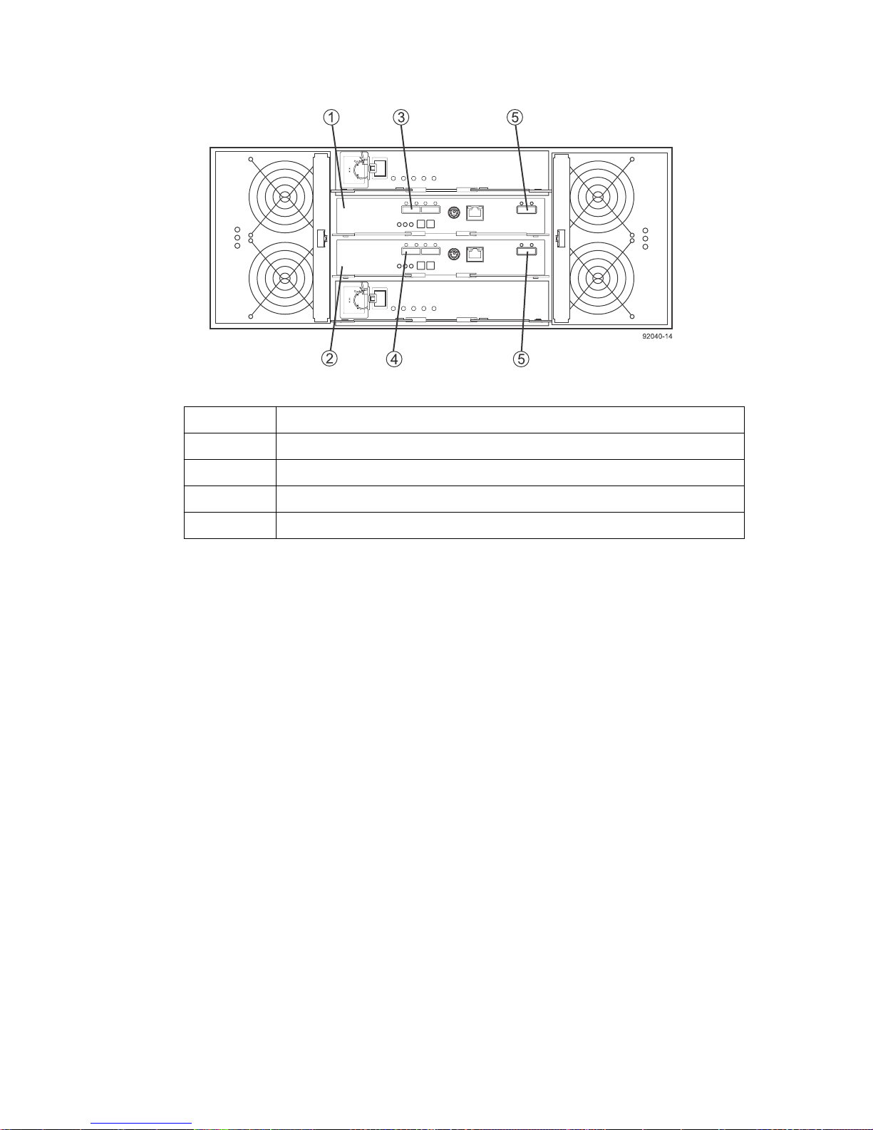
| E2700 Controller-Drive Tray and Related Drive Trays Installation Guide
86
1 ESM A
2 ESM B
3 SAS IN port
4 SAS IN port
5 SAS OUT ports
Things to know - Cabling configurations
The figures in this section show representative cabling configurations. The configurations shown
guarantee that redundant data paths exist between the controller-drive tray and all attached drive trays
in a storage array. You can attach the E2712 controller-drive tray, the E2724 controller-drive tray or
the E2760 controller-drive tray to DE1600 drive trays, DE5600 drive trays, DE6600 drive trays, or
various combinations of those three drive tray models.
You need four mini SAS-HD-to-mini SAS cables to attach one or two drive trays to the controllerdrive tray. For each additional drive tray, you need two more mini SAS-to-mini SAS cables. These
general rules apply:
• All cables connect a SAS Expansion (Out) port at one end to a SAS In port at the other end.
Never connect a SAS Expansion (Out) port to another SAS Expansion (Out) port. Never connect
a SAS In port to another SAS In port.
• You can use either of the two SAS IN ports on an ESM for a connection, but it is best to follow
the conventions described in the documentation so your storage management software represents
the storage array consistently.
• The drive trays in the chain of connections from controller A are in the reverse order from those
whose connections start from controller B. That is, in each drive tray stack the last drive tray in
the chain from controller A must be the first drive tray in the chain from controller B.
On all E2700 controller-drive tray models, the expansion connectors to the drive trays are always on
the right side of the controllers from the rear view. On all E2700 drive tray models, the input
connectors from the controllers to the drive trays are always in the middle of the ESMs and the
expansion connectors are on the right side of the ESMs from the rear view.
Note: Some SAS ports might have a black plastic plug installed. Remove the plug before you
attach a cable to the port.
Page 87
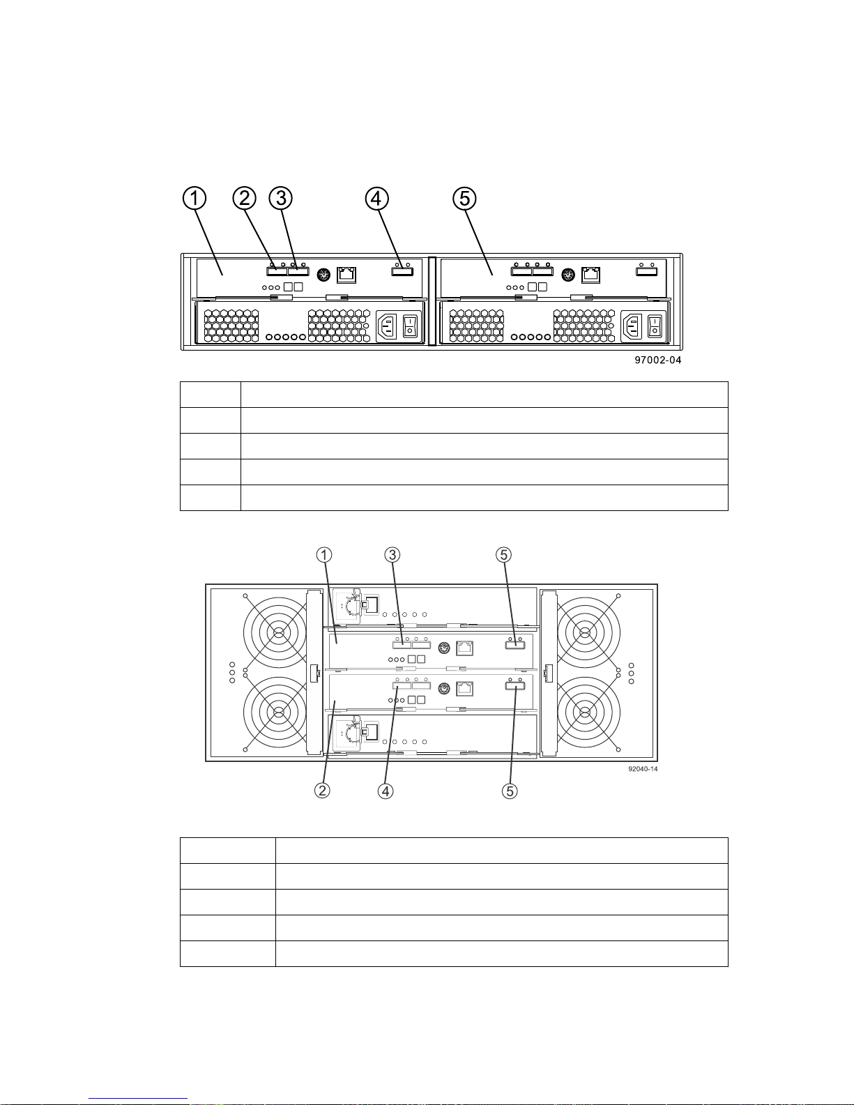
Step 7 - Connecting the controller-drive tray to the drive trays |
Note: If the storage array includes DE6600 drive trays, install those drive trays beginning from the
bottom of the rack so that the rack does not become top-heavy. A top-heavy rack has a greater risk
of falling over.
• Side-by-side ESMs in the DE1600 drive tray and the DE5600 drive tray
1 ESM A
2 SAS In Port 1
3 SAS In Port 2
87
4 SAS Out (Expansion) Port
5 ESM B
• Stacked ESMs in the DE6600 drive tray
1
ESM A
2 ESM B
3 SAS In Port
4 SAS In Port
5 SAS Out Ports
As you install each cable, attach labels to the cable with the following information:
• The controller ID (for example, controller A )
• The ESM ID (for example, ESM A)
Page 88

88 | E2700 Controller-Drive Tray and Related Drive Trays Installation Guide
• The ESM connector (In or Out)
• The drive tray ID
For example, if you are connecting controller A to the SAS In port on ESM A in drive tray 1, the
label on the controller end of the cable has this information:
CtA-Dch1, Dm1-ESM_A (left), In – Controller End
The label on the drive tray end of the cable has information:
Dm1-ESM_A (left), In, CtrlA
If you are connecting an ESM (Out) port to an ESM (In) port, the label on the first drive tray has
information:
Dm1-ESM_A (left), OUT, DM1 ESM_B (left)
E2700 controllers share two expansion SAS domains. The dual expansion ports allow external
bandwidth capability, as each port contains four PHYs on each E2700 controller.
You can connect a controller tray to drive trays using one of these patterns:
• Single stack
In a single stack pattern the expansion channels from each controller are paired by connecting
them to the same ESM. At least one expansion port from each controller must be connected to
each expansion channel on the ESM. For improved band-width to the expansion trays, connect
two ports from each controller to each expansion channel, one to the top of the stack and the other
to the bottom of the stack.
When there is only one drive tray, connect both controller expansion ports to the SAS IN ports on
the same ESM in a single stack to maximize performance.
• Dual stack
Dual stack cabling requires that both expansion ports on each controller are used for drive-side
cabling in order to create two logically separate stacks. Compared to single stack, dual stack
delivers the maximum possible bandwidth performance out of expansion enclosure when you
scale beyond one expansion enclosure.
When there is more than one drive tray, use a dual stack pattern to maximize performance. The
intention is to create two stacks, each stack cabled in either a top-down pattern or a bottom up
pattern. When an even number of expansion trays are used, the two stacks should each contain the
same number of expansion trays. When an odd number of expansion trays are used, one stack will
have one more tray than the other.
• One E2712 or E2724 controller-drive tray and one drive tray in a single stack
Page 89
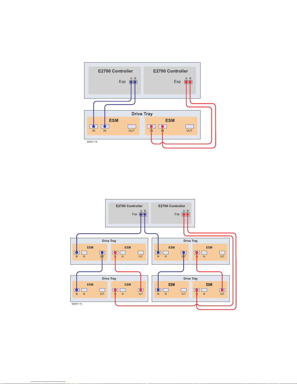
Step 7 - Connecting the controller-drive tray to the drive trays |
89
• One E2712 or E2724 controller-drive tray and four drive trays
• One E2760 controller-drive tray and one DE6600 drive tray in a single stack
Page 90
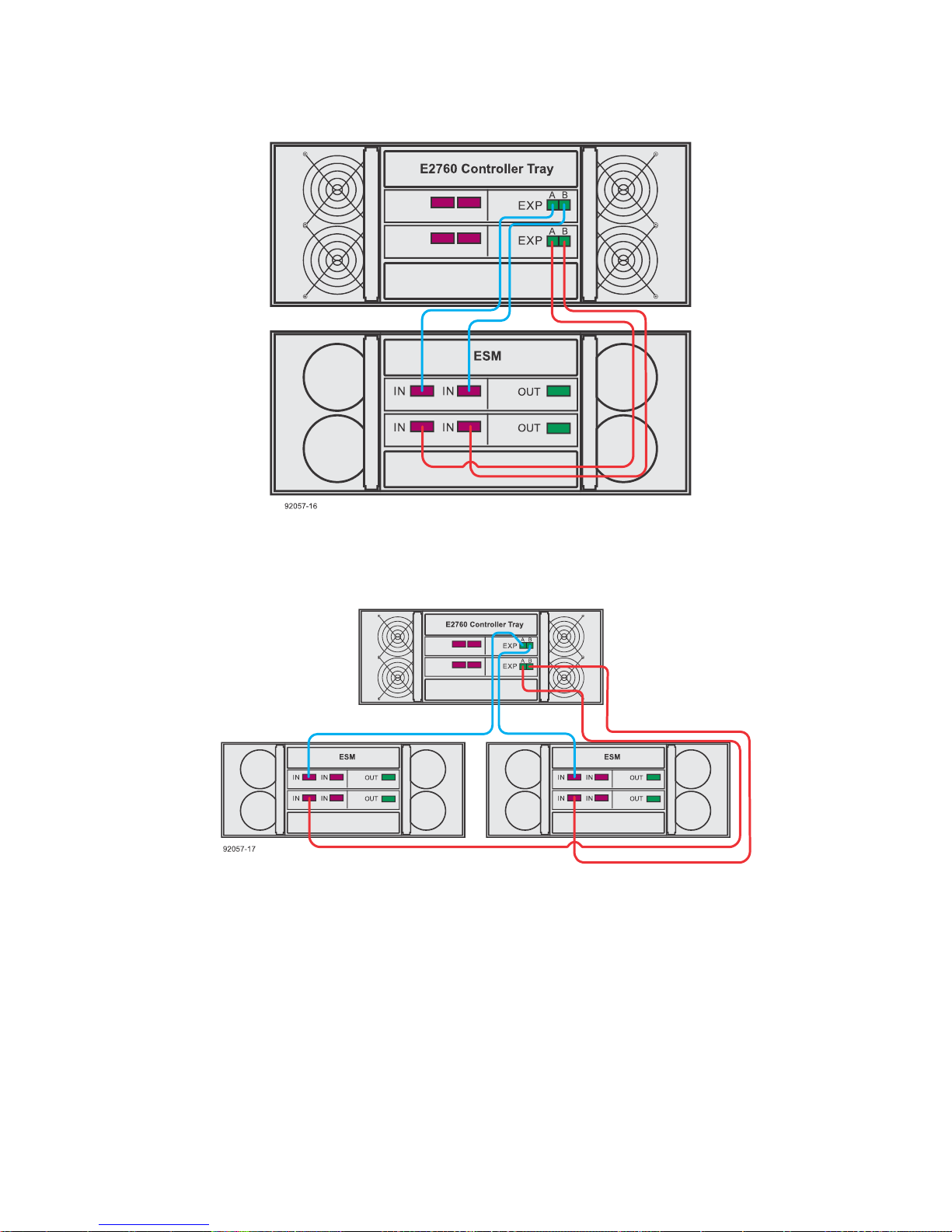
90 | E2700 Controller-Drive Tray and Related Drive Trays Installation Guide
• One E2760 controller-drive tray and two DE6600 drive trays
Page 91
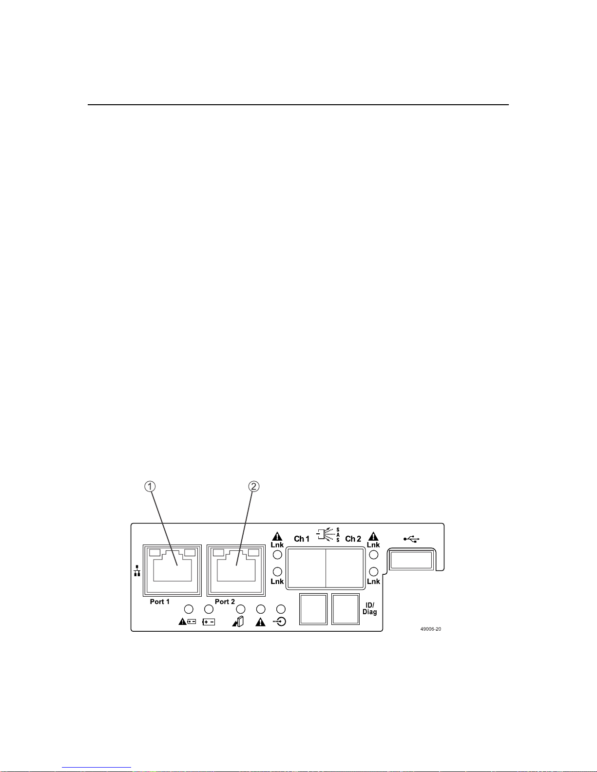
Step 8 - Connecting the Ethernet cables
Use this step if you are using out-of-band management for your storage array. If you use in-band
management, you can ignore this step and continue with
page 93.
Key terms
In-band management
A method to manage a storage array in which a storage management station sends commands to the
storage array through the host input/output (I/O) connection to the controller. The SMagent must be
installed for this method to work correctly.
Out-of-band management
A method to manage a storage array in which a storage management station sends commands to the
storage array through the Ethernet connections to the controller. This is the recommended
management method.
Step 9 - Connecting the power cords
91
on
Things to know - Connecting Ethernet cables
This topic describes Ethernet management connections. It does not describe the Ethernet iSCSI
connections that might be used through a host interface card connection.
Attention: Risk of security breach – Connect the Ethernet ports on the controller-drive tray to a
private network segment behind a firewall. If the Ethernet connection is not protected by a firewall,
your storage array might be at risk of being accessed from outside of your network.
The figure shows a controller with Ethernet port 1 and Ethernet port 2.
Note: Ethernet port 2 on each controller is reserved for access by technical support.
Because the controllers support the Auto-MDIX feature, you do not need an Ethernet crossover
cable.
Page 92

92 | E2700 Controller-Drive Tray and Related Drive Trays Installation Guide
Procedure - Connecting Ethernet cables
About this task
Perform these steps to connect Ethernet cables for out-of-band management.
Steps
Connect one end of an Ethernet cable into the Ethernet port 1 on controller A.
1.
Connect the other end of the cable to the applicable network connection.
2.
Repeat these steps for controller B.
3.
Page 93
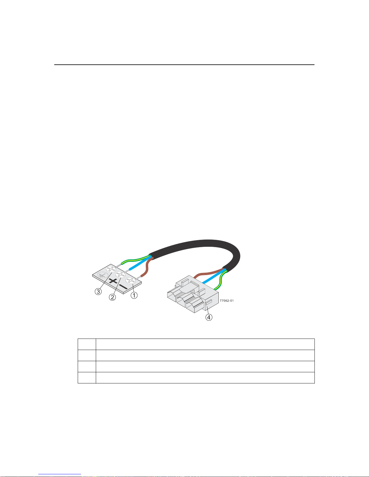
Step 9 - Connecting the power cords
Use the following information to connect the power cords in your storage array.
Things to know - AC power cords
• For each AC power connector on the drive tray, make sure that you use a separate power source in
the cabinet. Connecting to independent power sources maintains power redundancy.
• To ensure proper cooling, do not operate a drive tray with one of its power supplies removed,
unless instructed to do so by the Recovery Guru.
• You can use the power cords shipped with the controller-drive tray with typical outlets used in the
destination country, such as a wall receptacle or an uninterrupted power supply (UPS). These
power cords, however, are not intended for use in most EIA-compliant cabinets.
Things to know - DC power cords
93
Warning: (W14) Risk of bodily injury – A qualified service person is required to make the DC
power connection according to NEC and CEC guidelines.
• DC power cable
1
2 Return (positive), blue wire
3 Ground, green/yellow wire
4 DC power connector
Supply (negative), brown wire, –48 VDC
• Each power-fan canister has two DC power connectors. Be sure to use a separate power source
for each power-fan canister in the drive tray to maintain power redundancy. You can, optionally,
connect each DC power connector on the same power-fan canister to a different source for
additional redundancy.
• A two-pole 30-amp circuit breaker is required between the DC power source and the drive tray
for over-current and short-circuit protection.
Page 94
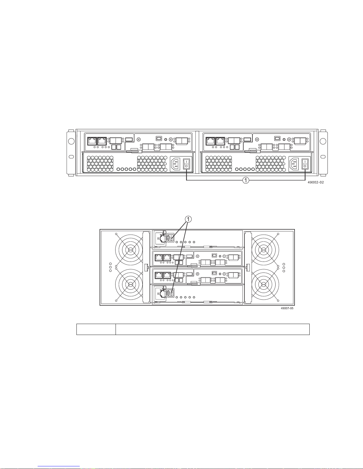
| E2700 Controller-Drive Tray and Related Drive Trays Installation Guide
94
Procedure - Connecting AC power cords
Steps
1. Ensure that the circuit breakers in the cabinet are turned off.
2. Ensure that both of the power switches on the controller-drive tray are turned off.
• Power switches on the E2712 and E2724 controller-drive trays
• Power switches on the E2760 controller-drive tray
1
3. Connect the primary power cords from the cabinet to the external power source.
4. Connect either a cabinet interconnect power cord, the power cords provided with the drive tray, or
the power cords specific to your particular cabinet to the AC power connector on each power
canister in the drive tray.
Power switches
5. If you are installing other drive trays in the cabinet, connect a power cord to each power canister
in the drive trays.
Page 95
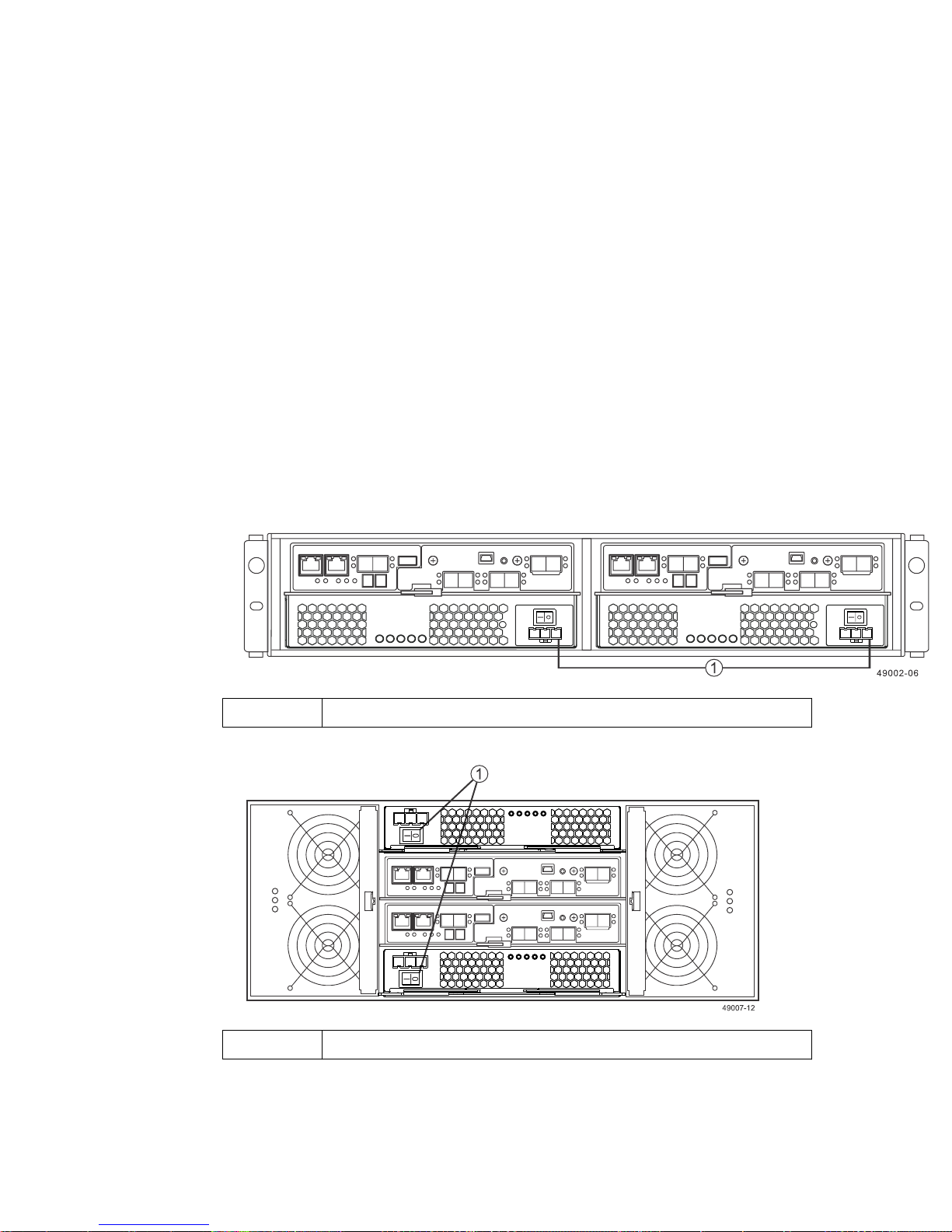
Step 9 - Connecting the power cords |
Procedure - Connecting DC power cords
About this task
Warning: (W14) Risk of bodily injury – A qualified service person is required to make the DC
power connection according to NEC and CEC guidelines.
Important: Make sure that you do not turn on the power to the controller-drive tray or the
connected drive trays until this documentation instructs you to do so.
Attention: Before turning off any power switches on a DC-powered controller-drive tray, you must
disconnect the two-pole 20-amp circuit breaker.
Steps
Disconnect the two-pole 20-amp circuit breaker for the storage array.
1.
Make sure that all of the DC power switches on the DC-powered controller-drive tray are turned
2.
off.
• Power switches on the E2712 or the E2724 controller-drive tray
95
1
Power switches
• Power switches on the E2760 controller-drive tray
1
Power switches
3. Make sure that all of the DC power switches on the DC-powered drive trays are turned off.
4. Connect the DC power connector cables to the DC power connectors on the rear of the controller-
drive tray and the drive trays.
Page 96

96 | E2700 Controller-Drive Tray and Related Drive Trays Installation Guide
Note: The three source wires on the DC power connector cable (–48 VDC) connect the
controller-drive tray to centralized DC power plant equipment, typically through a bus bar
located above the cabinet.
Note: You do not have to connect the second DC power on each of the drive tray’s DC power-
fan canisters. The second DC power connection is for additional redundancy only and can be
connected to a second DC power bus.
5. Have a qualified service person connect the other end of the DC power connector cables to the
DC power plant equipment as follows:
a. Connect the brown –48 VDC supply wire to the negative terminal.
b. Connect the blue return wire to the positive terminal.
c. Connect the green/yellow ground wire to the ground terminal.
Page 97

Step 10 - Turning on the power and checking for
problems in a controller-drive tray configuration
After you complete this task, you can install the software and perform basic configuration tasks on
your storage array. Continue with either the appropriate Express Guide or the
Installation Reference
Center
.
, available from the
NetApp E-Series and EF-Series Systems Documentation
Procedure - Turning on the power to the storage array and
checking for problems in a controller-drive tray
configuration
About this task
You must turn on the power to all of the connected drive trays before you turn on power for the
controller-drive trays. Performing this action ensures that the controllers recognize each attached
drive tray.
SANtricity Software
97
Note: While the power is being applied to the trays, the LEDs on the front and the rear of the trays
come on and go off intermittently.
Steps
1. Turn on both power switches on each drive tray that is attached to the controller-drive tray.
Depending on your configuration, it can take several minutes for each drive tray to complete the
power-on process.
2. Check the ESM Power LED and the Host Link Active LEDs on the drive trays to verify that the
power was successfully applied to all of the drive trays. You must wait for all the drives to come
online (persistent green LEDs) before turning on the power to the controller-drive tray.
3. Turn on both power switches on the rear of the controller-drive tray.
Depending on your configuration, it can take up to ten minutes for the controller-drive tray to
complete the power-on process. The controllers reboot several times during the initial startup
sequence, which causes the fans to ramp up and down and the LEDs to flash on and off.
4. Check the LEDs on the front and the rear of the controller-drive trays and the attached drive trays.
5. If you see any amber LEDs, make a note of their location.
Page 98
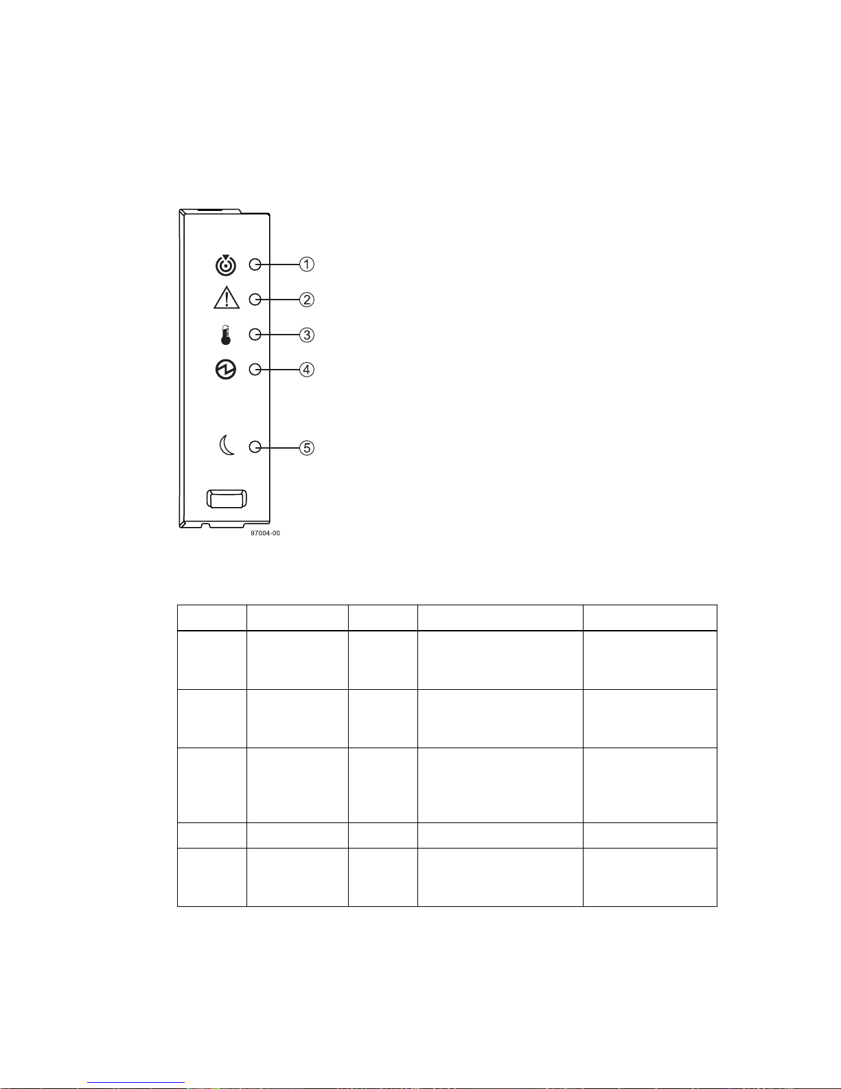
| E2700 Controller-Drive Tray and Related Drive Trays Installation Guide
98
Things to know - LEDs on the controller-drive tray
• LEDs on the left end cap
Table 9: LEDs on the left end cap
Location
1 Controller-
2 Service Action
3 Controller-
4 Power Green Power is present. Power is not present.
5 Standby Power Green The controller-drive tray is
• LEDs on the drive
LED Color On Off
Drive Tray
Locate
Required
Drive Tray
OverTemperature
White Identifies a controller-drive
tray that you are trying to
find.
Amber A component within the
controller-drive tray needs
attention.
Amber The temperature of the
controller-drive tray has
reached an unsafe level.
in Standby Power mode.
Normal status.
Normal status.
Normal status.
The controller-drive
tray is not in Standby
Power mode.
Page 99
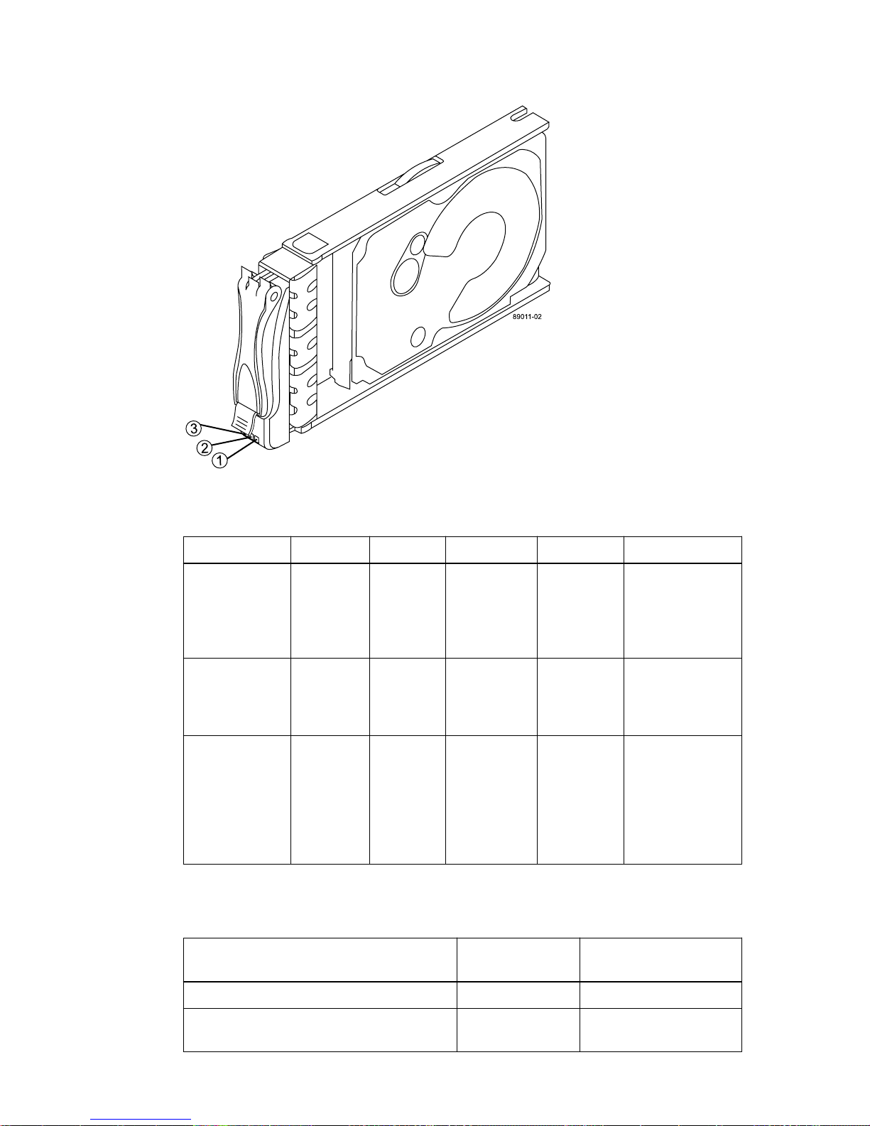
Step 10 - Turning on the power and checking for problems in a controller-drive tray configuration | 99
Table 10: LEDs on the drive
Location
LED Color On Blinking Off
1 Drive
Power
2 Drive
Service
Action
Required
3 Drive
Service
Action
Allowed
• Drive states represented by LEDs
Green The power is
turned on,
and the drive
is operating
normally.
Amber An error has
occurred.
Blue The drive
canister can
be removed
safely from
the
controllerdrive tray.
Drive I/O
activity is
taking place.
The power is
turned off.
Normal status.
The drive canister
cannot be
removed safely
from the
controller-drive
tray.
Table 11: Drive states represented by LEDs
Drive state
Power is not applied. Off Off
Normal operation – The power is turned on,
but drive I/O activity is not occurring.
Drive Power LED
(Green)
Drive Service Action
Required LED (Amber)
On Off
Page 100
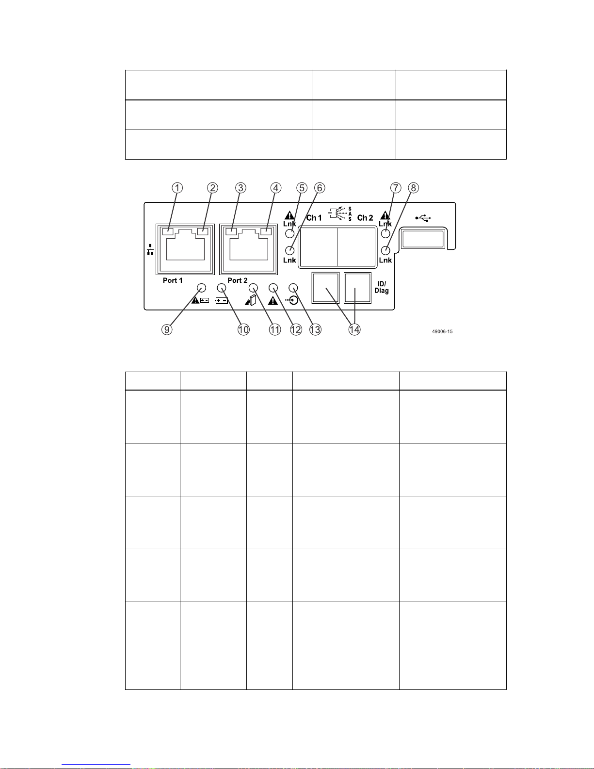
100 | E2700 Controller-Drive Tray and Related Drive Trays Installation Guide
Drive state Drive Power LED
(Green)
Normal operation – Drive I/O activity is
Blinking Off
occurring.
Service action required – A fault condition
On On
exists, and the drive is offline.
• LEDs on the controller canister main faceplate
Table 12: LEDs on the controller canister main faceplate
Drive Service Action
Required LED (Amber)
Location
LED Color On Off
1 Ethernet
Connector 1
Link Rate
LED
2 Ethernet
Connector 1
Link Active
LED
3 Ethernet
Connector 2
Link Rate
LED
4 Ethernet
Connector 2
Link Active
LED
5 Host Link 1
Service
Action
Required LED
Green There is a 1000 Gb/s
rate.
Green The link is up (LED
blinks when there is
activity).
Green There is a 1000 Gb/s
rate.
Green The link is up (the LED
blinks when there is
activity).
Amber At least one of the four
PHYs is working, but
another PHY cannot
establish the same link
to the device connected
to the Host IN port
connector.
There is a 10BASE-T
rate.
The link is not active.
There is a 10BASE-T
rate.
The link is not active.
No link error has
occurred.
 Loading...