

Page 1

NetApp™ Hardware
E2600 Controller-Drive Tray and Related Drive Trays
NetApp, Inc.
495 East Java Drive
Sunnyvale, CA 94089 U.S.A.
Telephone: +1 (408) 822-6000
Fax: +1 (408) 822-4501
Support telephone: +1 (888) 4-NETAPP
Document comments: [email protected]
Information Web: http://www.netapp.com
Part number: 53014-00, Rev. A
March 2012
Page 2

Copyright information
Copyright © 1994–2012 NetApp, Inc. All rights reserved. Printed in the U.S.A.
No part of this document covered by copyright may be reproduced in any form or by any means—
graphic, electronic, or mechanical, including photocopying, recording, taping, or storage in an
electronic retrieval system—without prior written permission of the copyright owner.
Software derived from copyrighted NetApp material is subject to the following license and disclaimer:
THIS SOFTWARE IS PROVIDED BY NETAPP "AS IS" AND WITHOUT ANY EXPRESS OR
IMPLIED WARRANTIES, INCLUDING, BUT NOT LIMITED TO, THE IMPLIED WARRANTIES
OF MERCHANTABILITY AND FITNESS FOR A PARTICULAR PURPOSE, WHICH ARE
HEREBY DISCLAIMED. IN NO EVENT SHALL NETAPP BE LIABLE FOR ANY DIRECT,
INDIRECT, INCIDENTAL, SPECIAL, EXEMPLARY, OR CONSEQUENTIAL DAMAGES
(INCLUDING, BUT NOT LIMITED TO, PROCUREMENT OF SUBSTITUTE GOODS OR
SERVICES; LOSS OF USE, DATA, OR PROFITS; OR BUSINESS INTERRUPTION) HOWEVER
CAUSED AND ON ANY THEORY OF LIABILITY, WHETHER IN CONTRACT, STRICT
LIABILITY, OR TORT (INCLUDING NEGLIGENCE OR OTHERWISE) ARISING IN ANY WAY
OUT OF THE USE OF THIS SOFTWARE, EVEN IF ADVISED OF THE POSSIBILITY OF SUCH
DAMAGE.
NetApp reserves the right to change any products described herein at any time, and without notice.
NetApp assumes no responsibility or liability arising from the use of products described herein, except
as expressly agreed to in writing by NetApp. The use or purchase of this product does not convey a
license under any patent rights, trademark rights, or any other intellectual property rights of NetAp p.
RESTRICTED RIGHTS LEGEND: Use, duplication, or disclosure by the government is subject to
restrictions as set forth in subparagraph (c)(1)(ii) of the Rights in Technical Data and Computer
Software clause at DFARS 252.277-7103 (October 1988) and FAR 52-227-19 (June 1987)
ii
Page 3

Trademark information
NetApp, the NetApp logo, Network Appliance, the Network Appliance logo, Akorri, ApplianceWatch,
ASUP, AutoSupport, BalancePoint, BalancePoint Predictor, Bycast, Campaign Express,
ComplianceClock, Cryptainer, CryptoShred, Data ONTAP, DataFabric, DataFort, Decru, Decru
DataFort, DenseStak, Engenio, Engenio logo, E-Stack, FAServer, FastStak, FilerView, FlexCache,
FlexClone, FlexPod, FlexScale, FlexShare, FlexSuite, FlexVol, FPolicy, GetSuccessful, gFiler, Go
further, faster, Imagine Virtually Anything, Lifetime Key Management, LockVault, Manage ONTAP,
MetroCluster, MultiStore, NearStore, NetCache, NOW (NetApp on the Web), Onaro, OnCommand,
ONTAPI, OpenKey, PerformanceStak, RAID-DP, ReplicatorX, SANscreen, SANshare, SANtricity,
SecureAdmin, SecureShare, Select, Service Builder, Shadow Tape, Simplicity, Simulate ONTAP,
SnapCopy , SnapDirector, SnapDrive, SnapFilter, SnapLock, SnapManager, SnapMigrator,
SnapMirror, SnapMover, SnapProtect, SnapRestore, Snapshot, SnapSuite, SnapValidator, SnapVault,
StorageGRID, StoreVault, the StoreVault logo, SyncMirror, Tech OnTap, The evolution of storage,
Topio, vFiler, VFM, Virtual File Manager, VPolicy, WAFL, Web Filer, and XBB are trademarks or
registered trademarks of NetApp, Inc. in the United States, other countries, or both.
IBM, the IBM logo, and ibm.com are trademarks or registered trademarks of International Business
Machines Corporation in the United States, other countries, or both. A complete and current list of
other IBM trademarks is available on the Web at
Apple is a registered trademark and QuickTime is a trademark of Apple, Inc. in the U.S.A. and/or other
countries. Microsoft is a registered trademark and Windows Media is a trademark of Microsoft
Corporation in the U.S.A. and/or other countries. RealAudio, RealNetworks, RealPlayer, RealSystem,
RealText, and RealVideo are registered trademarks and RealMedia, RealProxy, and SureStream are
trademarks of RealNetworks, Inc. in the U.S.A. and/or other countries.
www.ibm.com/legal/copytrade.shtml.
All other brands or products are trademarks or registered trademarks of their respective holders and
should be treated as such.
NetApp, Inc. is a licensee of the CompactFlash and CF Logo trademarks.
NetApp, Inc. NetCache is certified RealSystem compatible.
iii
Page 4

iv
Page 5

Table of Contents
Step 1 - Preparing for an E2600 Controller-Drive Tray Installation . . . . . . . . . . . . . . . . . . . . . . . . . . . . . . . . . . . 1
Key Terms . . . . . . . . . . . . . . . . . . . . . . . . . . . . . . . . . . . . . . . . . . . . . . . . . . . . . . . . . . . . . . . . . . . . . . . . . . . . 3
storage array . . . . . . . . . . . . . . . . . . . . . . . . . . . . . . . . . . . . . . . . . . . . . . . . . . . . . . . . . . . . . .
controller-drive tray . . . . . . . . . . . . . . . . . . . . . . . . . . . . . . . . . . . . . . . . . . . . . . . . . . . . . . . . . .
controller. . . . . . . . . . . . . . . . . . . . . . . . . . . . . . . . . . . . . . . . . . . . . . . . . . . . . . . . . . . . . . . .
drive tray. . . . . . . . . . . . . . . . . . . . . . . . . . . . . . . . . . . . . . . . . . . . . . . . . . . . . . . . . . . . . . . .
environmental services module (ESM) . . . . . . . . . . . . . . . . . . . . . . . . . . . . . . . . . . . . . . . . . . . . . . . . . . 3
Small Form-factor
Gathering Items . . . . . . . . . . . . . . . . . . . . . . . . . . . . . . . . . . . . . . . . . . . . . . . . . . . . . . . . . . . . . .
Basic Hardware . . . . . . . . . . . . . . . . . . . . . . . . . . . . . . . . . . . . . . . . . . . . . . . . . . . . . . . . . . . . . .
E2600 Configuration Cables and Connectors . . . . . . . . . . . . . . . . . . . . . . . . . . . . . . . . . . . . . . . . . . . . . 5
Product DVDs .
Tools and Other Items . . . . . . . . . . . . . . . . . . . . . . . . . . . . . . . . . . . . . . . . . . . . . . . . . . . . . . . . . .
Things to Know – SFP Transceivers, Fiber-Optic Cables, Copper Cables, and SAS Cables.
Things to Know – Taking a Quick Glance at the Hardware in a E2612 Controller-Drive Tray
or a E2624 Controller-Drive Tray Configuration . . . . . . . . . . . . . . . . . . . . . . . . . . . . . . . . . . . . . . . . . . . . .
Things to Know – Taking a Quick Glance at the Hardware
in a E2660 Controller-Drive Tray Configuration . . .
For Additional Information on the E2600 Controller-Drive Tray Configuration . . .
Pluggable (SFP) transceiver. . . .
. . . . . . . . . . . . . . . . . . . . . . . . . . . . . . . . . . . . . . . . . . . . . . . . . . . . . . . . . . . . . .
. . . . . . . . . . . . . . . . . . . . . . . . . . . . . . . . . . . . . . . . 4
. . . . . . . . . . . . . . . . . . . . . . . . . . . . . . . . . . . . . . . . . . 18
. . . . . . . . . . . . . . . . . . 23
. . . . . . . . . 3
. . . . . . . 3
. . . . . . . . . . 3
. . . . . . . . . . 3
. . . . . . . . . . 4
. . . . . . 4
. . . . . . 8
. . . . . 8
. . . . . . . . . . . . 9
11
Step 2 - Installing and Configuring the Switches . . . . . . . . . . . . .
Things to Know – Switches, Routers, and SFPs . . . .
Procedure – Installing and Configuring Switches . . . . . . . . . . . . . . . . . . . . . . . . . . . . . . . . . . . . . . . . . . . . .
Step 3 - Installing the Host Bus Adapters for the E2600 Controller-Drive Tray. .
Key Terms . . . . . . . . . . . . . . . . . . . . . . . . . . . . . . . . . . . . . . . . . . . . . . . . . . . . . . . . . . . . . . . .
HBA host port. . . . . . . . . . . . . . . . . . . . . . . . . . . . . . . . . . . . . . . . . . . . . . . . . . . . . . . . . . . . . . .
HBA host port world wide name . . . . .
host bus adapter (HBA) . . . . . . . . . . . . . . . . . . . . . . . . . . . . . . . . . . . . . . . . . . . . . . . . . . . . . . . . .
Table of Contents v
. . . . . . . . . . . . . . . . . . . . . . . . . . . . . . . . . . . . . . . . . . . . . . . . . 29
. . . . . . . . . . . . . . . . . . . . . . . . . . . . . . . . . . . . . 25
. . . . . . . . . . . . . . . . . . . . . . . . . . . . . . . . . . . . . . . . . . 25
27
. . . . . . . . . . . . . . . . . . . . . . . 29
. . . . . . . . . . . 29
. . . . . . 29
. . . . 29
Page 6

Things to Know – Host Bus Adapters and Ethernet Network Interface Cards . . . . . . . . . . . . . . . . . . . . . . . 29
Procedure – Installing Host Bus Adapters. . . . . . . . . . . . . . . . . . . . . . . . . . . . . . . . . . . . . . . . . . . . . . . . . . . 29
Step 4 - Installing the E2600 Controller-Drive Tray . . . .
Things to Know – General Installation . . . . . . .
. . . . . . . . . . . . . . . . . . . . . . . . . . . . . . . . . . . . . . . . . . . 31
. . . . . . . . . . . . . . . . . . . . . . . . . . . . . . . . . . . . . . . . . . . . . . 31
Procedure – Installing the E2600 Controller-Drive Tray . . . . . . . . . . . . . . . . . . . . . . . . . . . . . . . . . . . . . . . 31
Pr
ocedure – Installing the E2660 Controller-Drive Tray . . . . . . . . . . . . . . . . . . . . . . . . . . . . . . . . . . . . . . . 34
Step 5
- Connecting the E2600 Controller-Drive Tray to the Hos
ts . . . . . . . . . . . . . . . . . . . . . . . . . . . . . . . . . . . 45
Key Terms . . . . . . . . . . . . . . . . . . . . . . . . . . . . . . . . . . . . . . . . . . . . . . . . . . . . . . . . . . . . . . . .
direct topology . . . . . . . . . . . . . . . . . . . . . . . . . . . . . . . . . . . . . . . . . . . . . . . . . . . . . . . . . . . . . .
switch topology . . . . . . . . . . . . . . . . . . . . . . . . . . . . . . . . . . . . . . . . . . . . . . . . . . . . . . . . . . . . .
topology . . . . . . . . . . . . . . . . . . . . . . . . . . . . . . . . . . . . . . . . . . . . . . . . . . . . . . . . . . . . . . . .
Things to Know – Host Channels . . . . . . . . . . . . . . . . . . . . . . . . . . . . . . . . . . . . . . . . . . . . . . . . . . . . .
Procedure – Connecting Host Cables on a E2600 Controller-Drive Tray. .
. . . . . . . . . . . . . . . . . . . . . . . . . 46
Step 6 - Installing the Drive Trays for the E2600 Controller-Drive Tray Configurations
Things to Know – General Installation of Drive Trays with the E2600 Controller-Drive Tray . . . . . . . . . . 55
Procedure – Installing the DE1600 Drive Trays and the DE5600 Drive Trays . . . . . . . . . . . . . . . . . . . . . . 55
. . . . . . . . . . . 45
. . . . . . 45
. . . . . . 45
. . . . . . . . . 45
. . . . 45
. . . . . . . . . . . . . . . . . 55
Procedure – Installing Drives in the DE1600 Drive Trays and the DE5600 Drive Trays. . . . . . . . . . . . . . . 64
Things to Know – General Installation of Drive Trays with the E2660 Controller-Drive Tray . . . . . . . . . . 66
Steps to Install –DE6600 Drive Tray. . . . . . . . . . . . . . . . . . . . . . . . . . . . . . . . . . . . . . . . . . . . . . .
Steps to Install – Drives on the DE6600 Drive Tray. . . .
Step 7 - Connecting the E2600 Controller-Drive Tray to the Drive Trays
. . . . . . . . . . . . . . . . . . . . . . . . . . . . . . . . . . . . . . . 77
. . . . . . . . . . . . . . . . . . . . . . . . . . . . . . 81
Key Terms . . . . . . . . . . . . . . . . . . . . . . . . . . . . . . . . . . . . . . . . . . . . . . . . . . . . . . . . . . . . . . . .
drive channel . . . . . . . . . . . . . . . . . . . . . . . . . . . . . . . . . . . . . . . . . . . . . . . . . . . . . . . . . . . . . . .
Things to Know – E2600 Controller-Drive Tray . . . . . . . . . . . . . . .
Things to Know – Drive Trays with the E2600 Controller-Drive Tray . . .
Things to Know – Drive Tray Cabling Configurations – Simplex System .
Things to Know – Drive Tray Cabling Configurations – Duplex System .
vi Table of Contents
. . . . . . . . . . . . . . . . . . . . . . . . . . . . . . 81
. . . . . . . . . . . . . . . . . . . . . . . . . 82
. . . . . . . . . . . . . . . . . . . . . . . . . 82
. . . . . . . . . . . . . . . . . . . . . . . . . 83
. . . .
. . . . 67
. . . . . . . . . . . 81
. . . . . . 81
Page 7

Procedure – Connecting the DE1600 Drive Trays and the DE5600 Drive Trays . . . . . . . . . . . . . . . . . . . . . 85
Things to Know – E2660 Controller-Drive Tray . . . . . . . . . . . . . . . . . . . . . . . . . . . . . . . . . . . . . . . . . . . . . 87
Things to Know – Drive Trays with the E2660 Controller-Drive Tray . . .
Things to Know – E2660 Drive Tray Cabling Configurations – Duplex System . .
Procedure – Connecting the DE6600 Drive Tray . . . . . . . . . . . . . . . . . . . . . . . . . . . . . . . . . . . . . . . . . . . . . 89
Step 8
- Connecting the Ethernet Cables . . . .
. . . . . . . . . . . . . . . . . . . . . . . . . . . . . . . . . . . . . . . . . . . . . . . . . . . . . 91
Key Terms . . . . . . . . . . . . . . . . . . . . . . . . . . . . . . . . . . . . . . . . . . . . . . . . . . . . . . . . . . . . . . . .
in-band management . . . . . . . . . . . . . . . . . . . . . . . . . . . . . . . . . . . . . . . . . . . . . . . . . . . . . . . . . . .
out-of-band management . . . . . . . . . . . . . . . . . . . . . . . . . . . . . . . . . . . . . . . . . . . . . . . . . . . . . . . . . .
Things to Know – Connecting Ethernet Cables . . .
. . . . . . . . . . . . . . . . . . . . . . . . . . . . . . . . . . . . . . . . . . . 91
Procedure – Connecting Ethernet Cables . . . . . . . . . . . . . . . . . . . . . . . . . . . . . . . . . . . . . . . . . . . . . . . . .
Step 9 - Connecting the Power Cords. . . . . . . . . . . . . . . . . . . .
Things to Know – AC Power Cords . . . . . . . . . . . . . . . . . . . . . . . . . . . . . . . . . . . . . . . . . . . . . . . . . . . . .
Things to Know – DC Power Cords . . . . . . . . . . . . . . . . . . . . . . . . . . . . . . . . . . . . . . . . . . . . . . . . . . . . .
Procedure – Connecting AC Power Cords . . . . . . . . . . . . . . . . . . . . . . . . . . . . . . . . . . . . . . . . . . . . . . . . . .
Procedure – Connecting DC Power Cords . . . . . . . . . . . . . . . . . . . . . . . . . . . . . . . . . . . . . . . . . . . . . . . . . .
. . . . . . . . . . . . . . . . . . . . . . . . . 88
. . . . . . . . . . . . . . . . . . . 88
. . . . . . . . . . . 91
. . . . 91
. . 91
. . 91
. . . . . . . . . . . . . . . . . . . . . . . . . . . . . . . . . . . . . . . . 93
. . 93
. . 93
94
94
Step 10 - Turning on the Power and Checking for Problems
in a E2600
Controller-Drive Tray Configuration . . . . . . . . . . . . . . . . . . . . . . . . . . . . . . . . . . . . . . . . . . . . . . . . . . 95
Procedure – Turning On the Power to the Storage Array and Checking for Problems
in a E2600
Controller-Drive Tray Configuration . . .
Things to Know – LEDs on the E2600 Controller-Drive Tray . . . . . . . . .
Things to Know – LEDs on the E2660 Controller-Drive Tray . . . . . . . . .
. . . . . . . . . . . . . . . . . . . . . . . . . . . . . . . . . . . . . . . . . . 95
. . . . . . . . . . . . . . . . . . . . . . . . . . 96
. . . . . . . . . . . . . . . . . . . . . . . . . 102
Things to Know – General Behavior of the LEDs on the E2600 Controller-Drive Tray . . . . . . . . . . . . . . 108
Things to Know – Service Action Allowed LEDs . . . . . . . . . . . . . . .
. . . . . . . . . . . . . . . . . . . . . . . . . . . . 110
Things to Know – LEDs on the DE1600 Drive Tray and the DE5600 Drive Tray . . . . . . . . . . . . . . . . . . 111
Things to Know – LEDs on the DE6600 Drive Tray . . . . . . . . . . . . .
LEDs on the DE6600 Drive Drawers . . . . . . . . . . . . . . . . . . . . . . . . . . . . . . . . . . . . . . . . . . . . . . . . . . . . .
LEDs on the DE6600 Drives . . . . . . . . . . . . . . . . . . . . . . . . . . . . . . . . . . . . . . . . . . . . . . . . . . . . . . . .
. . . . . . . . . . . . . . . . . . . . . . . . . . . . 116
119
. . . . 120
General Behavior of the LEDs on the Drive Trays . . . . . . . . . . . . . . . . . . . . . . . . . . . . . . . . . . . . . . . . . . . 121
Table of Contents vii
Page 8

Things to Know – Seven Segment Component Failure Identifications
for the E2600 Controller-Drive Tray . . . . . . . . . . . . . . . . . . . . . . . . . . . . . . . . . . . . . . . . . . . . . . . . . . . . . 123
Things to Know – Seven Segment Display Sequence Code Definitions . . . . . . . . . . . . . . . . . . . . . . . . . . 123
Things to Know – Lock-Down Codes for the Controller-Drive Tray . . .
Things to Know – Seven-Segment Display Use Cases . . . .
Things to Know – Seven-Segment Display for the Drive Trays . . . . . . .
Regulatory Compliance Statements . . . . . . . . . . . . . . . . . . . . . .
. . . . . . . . . . . . . . . . . . . . . . . . . 125
. . . . . . . . . . . . . . . . . . . . . . . . . . . . . . . . . . . . 126
. . . . . . . . . . . . . . . . . . . . . . . . . 128
. . . . . . . . . . . . . . . . . . . . . . . . . . . . . . . . . . . FCC-1
viii Table of Contents
Page 9

Step 1 - Preparing for an E2600 Controller-Drive Tray Installation
Storage arrays for 6-Gb/s SAS drives consist of a E2600 controller-drive tray model and one or more drive trays in
a cabinet.
Use this document to install one of the following E2600 controller-drive tray models and all necessary drive trays
for your configuration:
E2612 controller-drive tray
E2624 controller-drive tray
E2660 controller-drive tray
The following tables (Tab le 1 and Ta
Table 1 E2612 Controller-Drive Tray and E2624 Controller-Drive Tray Options
E2600
Configurations
Simplex (one controller)
E2612 controller-drive
tray or E2624
controller-drive tray with
no host interface card
bl e 2 on page 2) show the various configuration options.
Options
A maximum of 96 drives that you can upgrade to 192. The upgrade is
a Premium feature.
Any combination of E2600 controller-drive trays attached to DE1600
drive trays or DE5600 drive trays, not to exceed a maximum of 96 (or
192) drive slots or 8 total trays in the storage array.
Two 6-Gb/s host connectors.
Options of 1-GB, 2-GB, or 4-GB memory for cache offload to flash
memory battery backup.
Simplex E2612
controller-drive tray or
E2624 controller-drive
tray with a host interface
card
A maximum of 96 drives that you can upgrade to 192. The upgrade is
a Premium feature.
Any combination of E2600 controller-drive trays attached to DE1600
drive trays or DE5600 drive trays, not to exceed a maximum of 96 (or
192) drive slots or 8 total trays in the storage array.
Two 6-Gb/s host connectors, in addition to one of the following host
interface cards:
Two 6-Gb/s SAS connectors
Four 1-Gb/s iSCSI connectors
Two 10-Gb/s iSCI connectors
Four 8-Gb/s Fibre Channel (FC) connectors
Options of 1-GB, 2-GB, or 4-GB memory for cache offload to flash
memory battery backup.
E2600 Controller-Drive Tray Installation Guide 1
Page 10
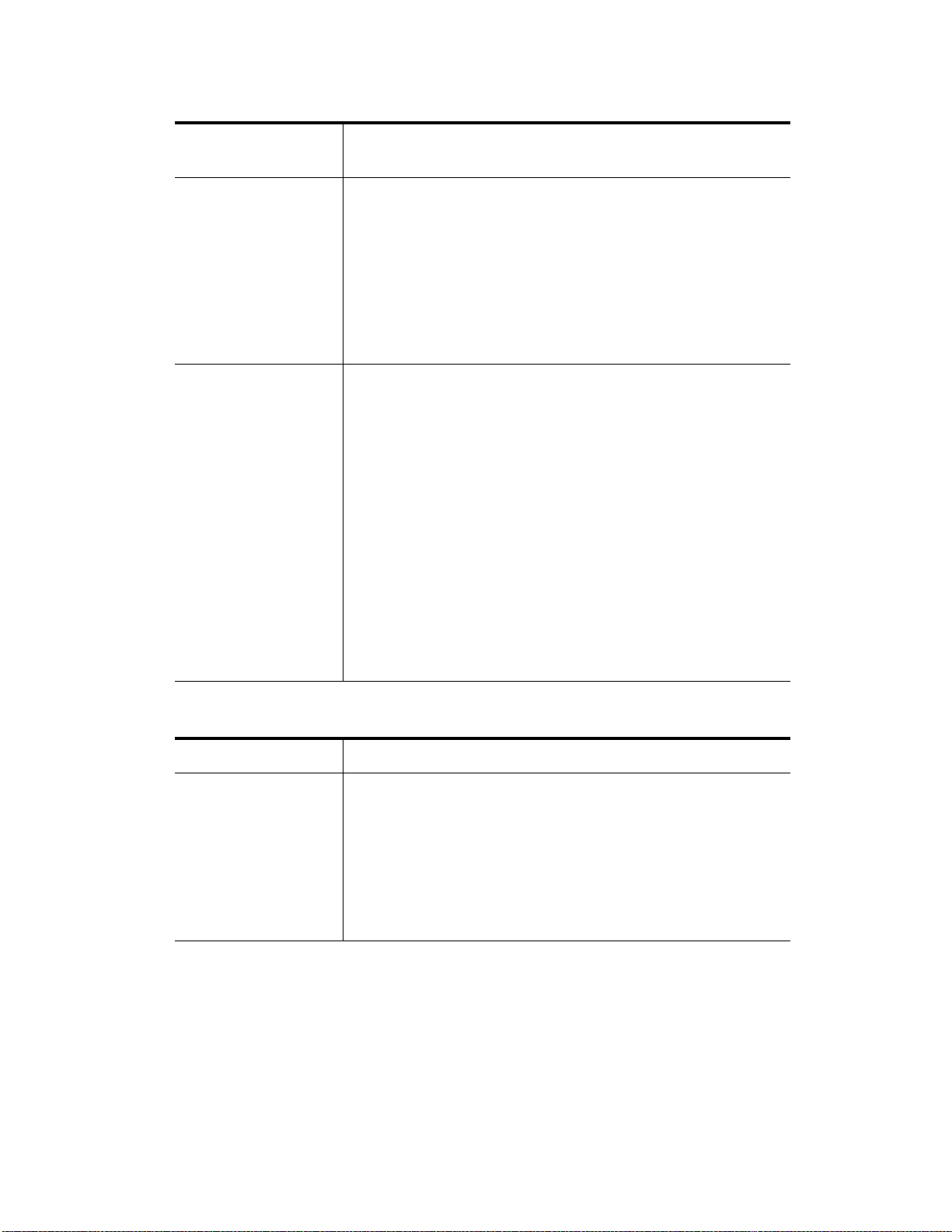
E2600
Configurations
Options
Duplex (two controllers)
E2612 controller-drive
tray or E2624
controller-drive tray
without a host interface
card
Duplex E2612
controller-drive tray or
E2624 controller-drive
tray with a host interface
card
A maximum of 96 drives that you can upgrade to 192. The upgrade is
a Premium feature.
Any combination of E2600 controller-drive trays attached to DE1600
drive trays or DE5600 drive trays, not to exceed a maximum of 96 (or
192) drive slots or 8 total trays in the storage array.
Two 6-Gb/s host connectors.
Options of 1-GB, 2-GB, or 4-GB memory for cache offload to flash
memory battery backup.
A maximum of 96 drives that you can upgrade to 192. The upgrade is
a Premium feature.
Any combination of E2600 controller-drive trays attached to DE1600
drive trays or DE5600 drive trays, not to exceed a maximum of 96 (or
192) drive slots or 8 total trays in the storage array.
Two 6-Gb/s host connectors, in addition to one of the following host
interface cards:
Two 6-Gb/s SAS connectors
Four 1-Gb/s iSCSI connectors
Two 10-Gb/s iSCI connectors
Four 8-Gb/s FC connectors
Options of 1-GB, 2-GB, or 4-GB memory for cache offload to flash
memory battery backup.
Table 2 E2660 Controller-Drive Tray Options
E2660 Configurations Options
Duplex (two controllers)
E2660 controller-drive
tray without a host
interface card
A maximum of 180 drives.
A configuration of a single E2660 controller-drive tray attached to
either one or two DE6600 drive trays, for a maximum of 180 drives in
the storage array.
Two 6-Gb/s host connectors.
Options of 1-GB, 2-GB, or 4-GB memory for cache offload to flash
memory battery backup.
2 E2600 Controller-Drive Tray Installation Guide
Page 11

E2660 Configurations Options
ATTENTION Possible hardware damage – To prevent electrostatic discharge damage to the tray, use proper
antistatic protection when handling tray components.
Key Terms
Duplex E2660
controller-drive tray with
a host interface card
A maximum of 180 drives in the storage array.
A configuration of a single E2660 controller-drive tray attached to
either one or two DE6600 drive trays, for a maximum of 180 drives in
the storage array.
Two 6-Gb/s host connectors, in addition to one of the following host
interface cards:
Two 6-Gb/s SAS connectors
Four 1-Gb/s iSCSI connectors
Two 10-Gb/s iSCI connectors
Four 8-Gb/s FC connectors
Options of 1-GB, 2-GB, or 4-GB memory for cache offload to flash
memory battery backup.
storage array
A collection of both physical components and logical components for storing data. Physical components include
drives, controllers, fans, and power supplies. Logical components include disk pools, volume groups, and volumes.
These components are managed by the storage management software.
controller-drive tray
One tray with drives, one or two controllers, fans, and power supplies. The controller-drive tray provides the
interface between a host and a storage array.
controller
A circuit board and firmware that is located within a controller tray or a controller-drive tray. A controller manages
the input/output (I/O) between the host system and data volumes.
drive tray
One tray with drives, one or two environmental services modules (ESMs), power supplies, and fans. A drive tray
does not contain controllers.
environmental services module (ESM)
A canister in the drive tray that monitors the status of the components. An ESM also serves as the connection point
to transfer data between the drive tray and the controller.
E2600 Controller-Drive Tray Installation Guide 3
Page 12
Small Form-factor Pluggable (SFP) transceiver
A component that enables Fibre Channel duplex communication between storage array devices. SFP transceivers
can be inserted into host bus adapters (HBAs), controllers, and environmental services modules (ESMs). SFP
transceivers can support either copper cables (the SFP transceiver is integrated with the cable) or fiber-optic cables
(the SFP transceiver is a separate component from the fiber-optic cable).
Gathering Items
Before you start installing the controller-drive tray, you must have installed the cabinet in which the controller-drive
tray will be mounted.
Use the tables in this section to verify that you have all of the necessary items to install the controller-drive tray.
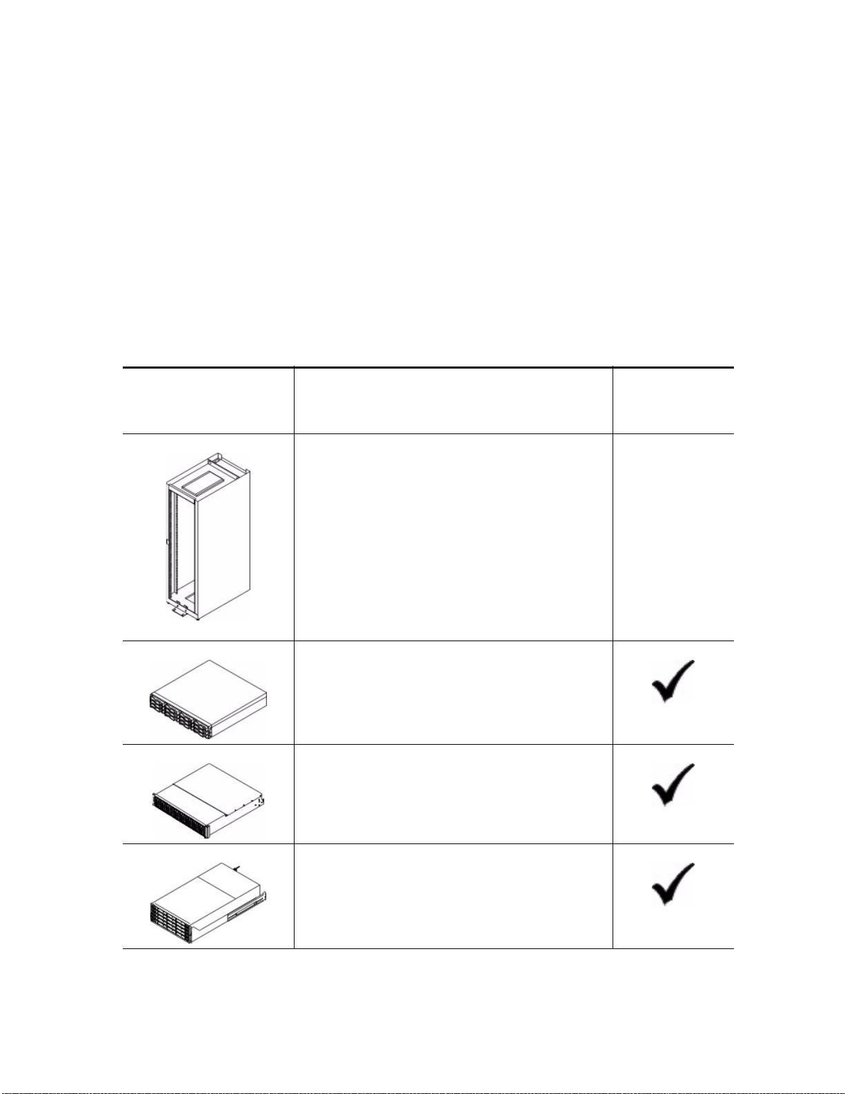
Basic Hardware
Table 3 Basic Hardware
Cabinet
Make sure that your cabinet meets the installation
site specifications of the various E2600 storage
array components. Refer to the Storage System Site
Preparation Guide for more information.
Item
Included with the
Controller-Drive
Tray
Depending on the power supply limitations of your
cabinet, you might need to install more than one
cabinet to accommodate the different components
of the E2600 storage array. Refer to the installation
guide for your cabinet for instructions on installing
the cabinet.
DE1600 drive tray with end caps that are packaged
separately. This drive tray can be used only with either a
E2612 controller-drive tray or a E2624 controller-drive
tray.
DE5600 drive tray with end caps that are packaged
separately. This drive tray can be used only with either a
E2612 controller-drive tray or a E2624 controller-drive
tray.
DE6600 drive tray (shown with the separately packaged
mounting rails attached). This drive tray can be used
only with a E2660 controller-drive tray.
4 E2600 Controller-Drive Tray Installation Guide
Page 13
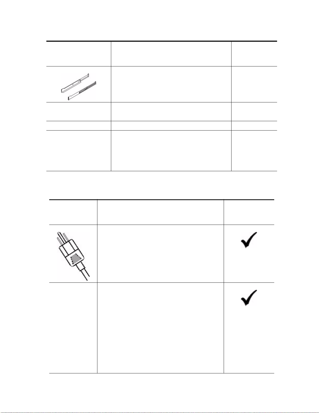
Mounting rails and screws
The mounting rails that are available with the drive tray
are designed for an industry-standard cabinet.
Fibre Channel switch (optional)
SAS switch (optional)
Gigabit Ethernet switch (optional)
Host with Fibre Channel host bus adapters (HBAs)
(optional)
Host with iSCSI HBAs (optional) or a network
interface card (optional)
Host with SAS HBAs (optional)
E2600 Configuration Cables and Connectors
Table 4 Cables and Connectors
Item
Included with the
Controller-Drive
Tray
Item
AC power cords.
The controller-drive tray and the drive trays ship with
power cords for connecting to an external power source,
such as a wall plug. Your cabinet might have special power
cords that you use instead of the power cords that ship with
the controller-drive tray and the drive trays.
(Optional) Two DC power connector cables are provided
with each drive tray for connection to centralized DC
power plant equipment.
Four DC power connector cables are provided if
additional redundancy is required.
A qualified service person is required to make the
DC power connection per NEC and CEC
guidelines. A two-pole 20-amp circuit breaker is
required between the DC power source and the drive
tray for over-current and short-circuit protection.
Before turning off any power switches on a
DC-powered drive tray, first you must disconnect the
two-pole 20-amp circuit breaker.
Included with the
Controller-Drive
Tray or Drive Trays
For the DC power
option only
E2600 Controller-Drive Tray Installation Guide 5
Page 14
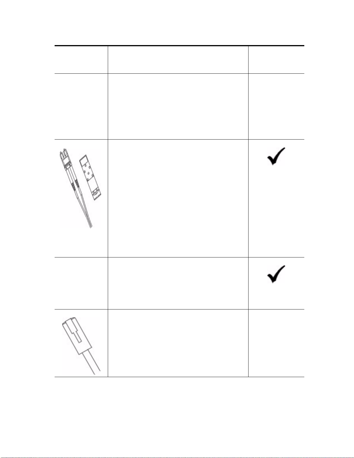
Item
Copper SAS cables - Use for all drive-side connections
within the storage array.
Fiber-optic cables - Use for FC connections to the drive
trays.
For the differences between the fiber-optic cables and the
copper Fibre Channel (FC) cables, see "Things to Know –
SFP Transceivers, Fiber-Optic Cables, Copper Cables, and
SAS Cables" on page 9.
Small Form-factor Pluggable (SFP) transceivers
The SFP transceivers connect fiber-optic cables to
host ports and drive ports.
Four or eight SFP transceivers are included with the
controller-drive tray; one for each of the host channel
ports on the controllers.
Depending on your connection requirements, you
might need to purchase additional SFP transceivers
(two SFP transceivers for each fiber-optic cable).
Included with the
Controller-Drive
Tray or Drive Trays
Depending on the configuration of your storage array,
you might need to use 8-Gb/s Fibre Channel SFP
transceivers.
You must purchase only Restriction of Hazardous
Substances (RoHS)-compliant SFP transceivers.
Copper Fibre Channel cables (optional)
Use these cables for connections within the storage array.
For the differences between the fiber-optic cables and the
copper Fibre Channel cables, see "Things to Know – SFP
Transceivers, Fiber-Optic Cables, Copper Cables, and SAS
Cables" on page 9.
Ethernet cable
This cable is used for out-of-band storage array
management and for 1-Gb/s iSCSI connections.
For information about out-of-band storage array
management, see the description for "Deciding on the
Management Method" in Initial Configuration and
Software Installation PDF on the SANtricity™ ES Storage
Manager Installation DVD.
6 E2600 Controller-Drive Tray Installation Guide
Page 15
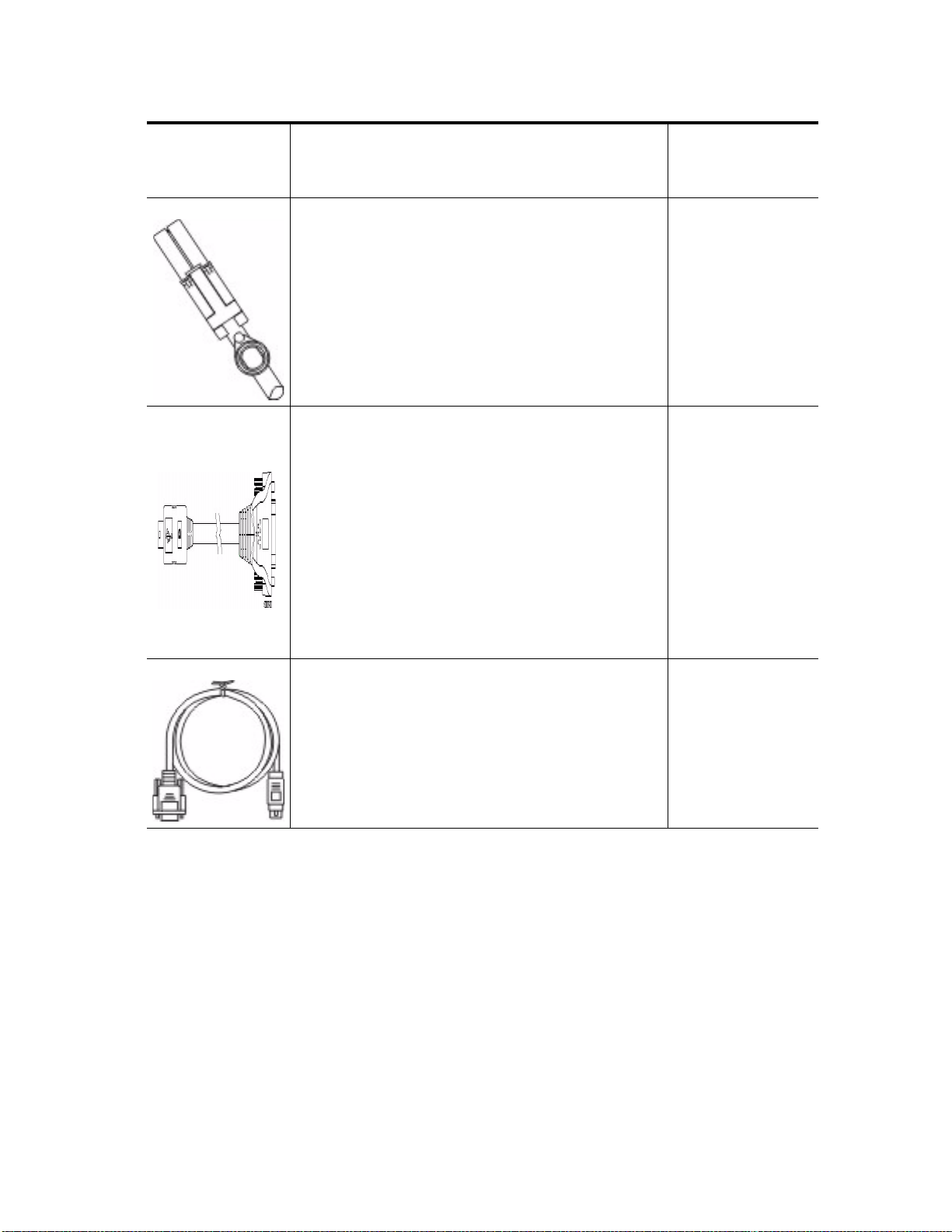
Item
SAS cables
The SAS cables connect the host to the controller-drive
tray. If you install a drive tray, you must use SAS cables to
connect the controller-drive tray to the drive tray.
Serial cable
This cable is used for support only. You do not need to
connect it during initial installation.
Included with the
Controller-Drive
Tray or Drive Trays
DB9-to-PS2 adapter cable
This cable adapts the DB9 connector on commercially
available serial cables to the PS2 connector on the
controller.
E2600 Controller-Drive Tray Installation Guide 7
Page 16
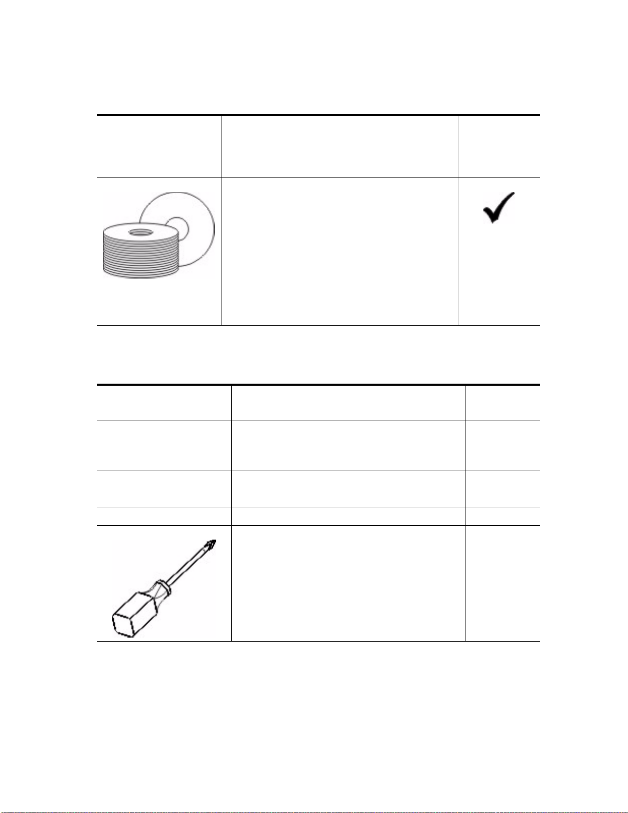
Product DVDs
Table 5 Product DVDs
Tools and Other Items
Table 6 Tools and Other Items
Item
Firmware DVD
Firmware is already installed on the controllers.
The files on the DVD are backup copies.
SANtricity ES Storage Manager Installation DVD
SANtricity ES Storage Manager software and
documentation.
To access product documentation, use the
documentation map file, doc_launcher.html,
which is located in the docs directory.
Included with
the
Controller-Drive
Tray
Item
Labels
Help you to identify cable connections and lets you
more easily trace cables from one tray to another
A cart
Holds the tray and components
A mechanical lift (optional)
A Phillips screwdriver
Included with
the Tray
8 E2600 Controller-Drive Tray Installation Guide
Page 17
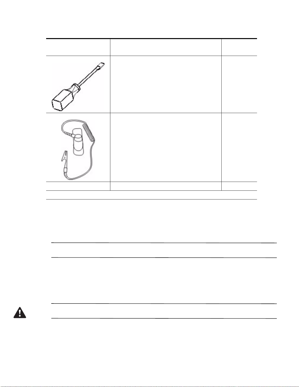
A flat-blade screwdriver
Anti-static protection
Item
Included with
the Tray
A flashlight
Consult your Technical Support representative to obtain the latest hardware compatibility information.
Things to Know – SFP Transceivers, Fiber-Optic Cables, Copper Cables, and
SAS Cables
The figures in this topic display the fiber-optic cables, copper cables, SFP transceivers and SAS cables with a
SFF-8088 Connector.
NOTE Your SFP transceivers and cables might look slightly different from the ones shown. The differences do not
affect the performance of the SFP transceivers.
The controller-drive tray supports SAS, Fibre Channel (FC), and iSCSI host connections and SAS drive
connections. FC host connections can operate at 8 Gb/s or at a lower data rate. Ports for 8-Gb/s Fibre Channel host
connections require SFP transceivers designed for this data rate. These SFP transceivers look similar to other SFP
transceivers but are not compatible with other types of connections. SFP transceivers for 1-Gb/s iSCSI and 10-Gb/s
iSCSI connections have a different physical interface for the cable and are not compatible with other types of
connections.
WARNING (W03) Risk of exposure to laser radiation – Do not disassemble or remove any part of a Small
Form-factor Pluggable (SFP) transceiver because you might be exposed to laser radiation.
E2600 Controller-Drive Tray Installation Guide 9
Page 18
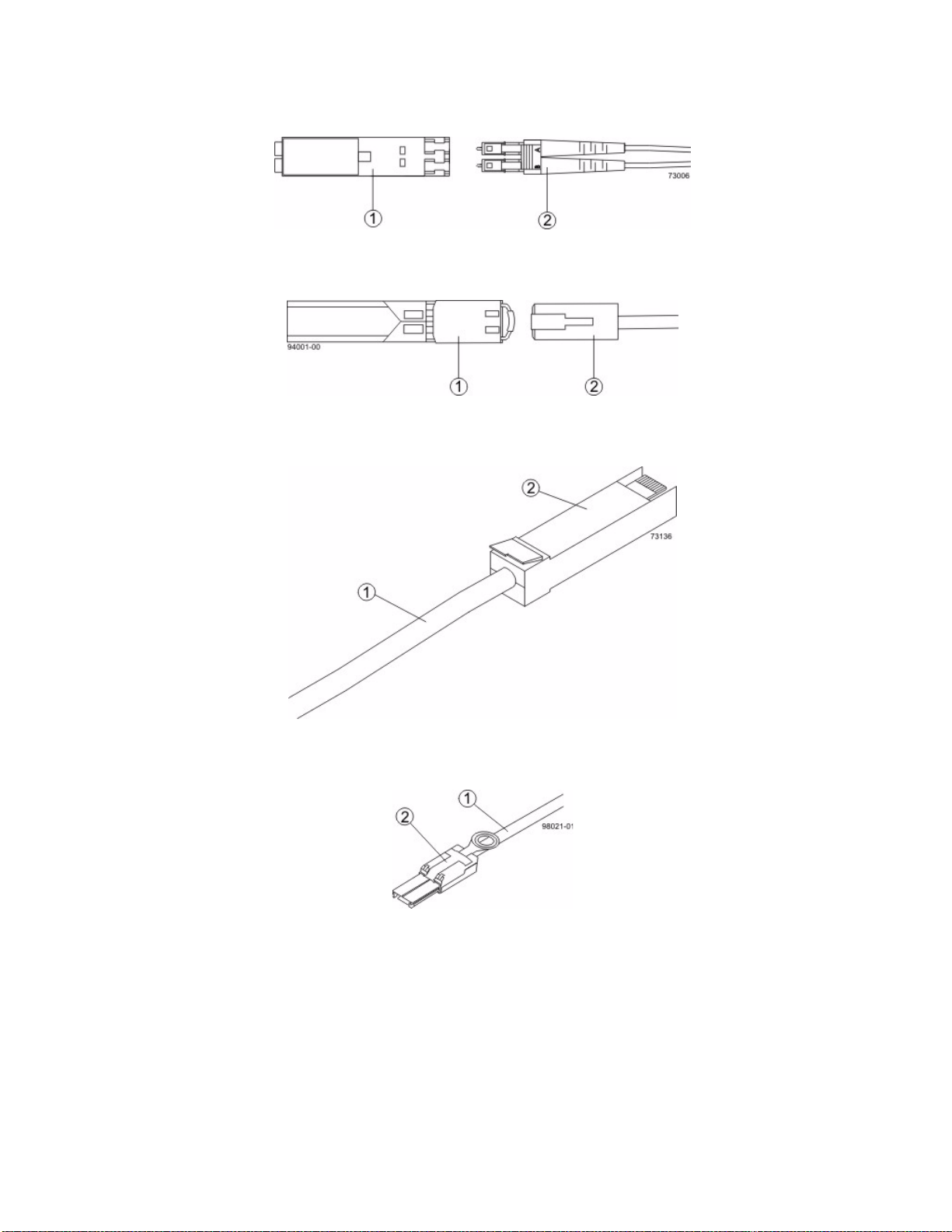
Figure 1 Fiber-Optic Cable Connection
1. Active SFP Transceiver
2. Fiber-Optic Cable
Figure 2 1-Gb/s iSCSI Cable Connection
1. Active SFP Transceiver
2. Copper Cable with RJ-45 Connector
Figure 3 Copper Fibre Channel Cable Connection
1. Copper Fibre Channel Cable
2. Passive SFP Transceiver
Figure 4 SAS Cable Connection
1. SAS Cable
2. SFF-8088 Connector
10 E2600 Controller-Drive Tray Installation Guide
Page 19
Things to Know – Taking a Quick Glance at the Hardware in a E2612
Controller-Drive Tray or a E2624 Controller-Drive Tray Configuration
WARNING (W14) Risk of bodily injury – A qualified service person is required to make the DC power
connection according to NEC and CEC guidelines.
CAUTION (C05) Electrical grounding hazard – This equipment is designed to permit the connection of the DC
supply circuit to the earthing conductor at the equipment.
NOTE Each tray in the storage array must have a minimum of two drives for proper operation.
NOTE iSCSI host ports do not support the Data Assurance (DA) premium feature.
ATTENTION Possible data loss – If you remove all Fibre Channel Host Interface Cards (HICs) from a storage
array and replace them with HICs of a different network protocol (such as iSCSI or SAS), you must first deactivate
the Remote Volume Mirroring (RVM) premium feature if it is activated. If you do not deactivate RVM before
removing the Fibre Channel HICs, your system loses data access and data loss might occur.
The top of the controller-drive tray is the side with labels.
The configuration of the host ports might appear different on your system depending on which host interface
card configuration is installed.
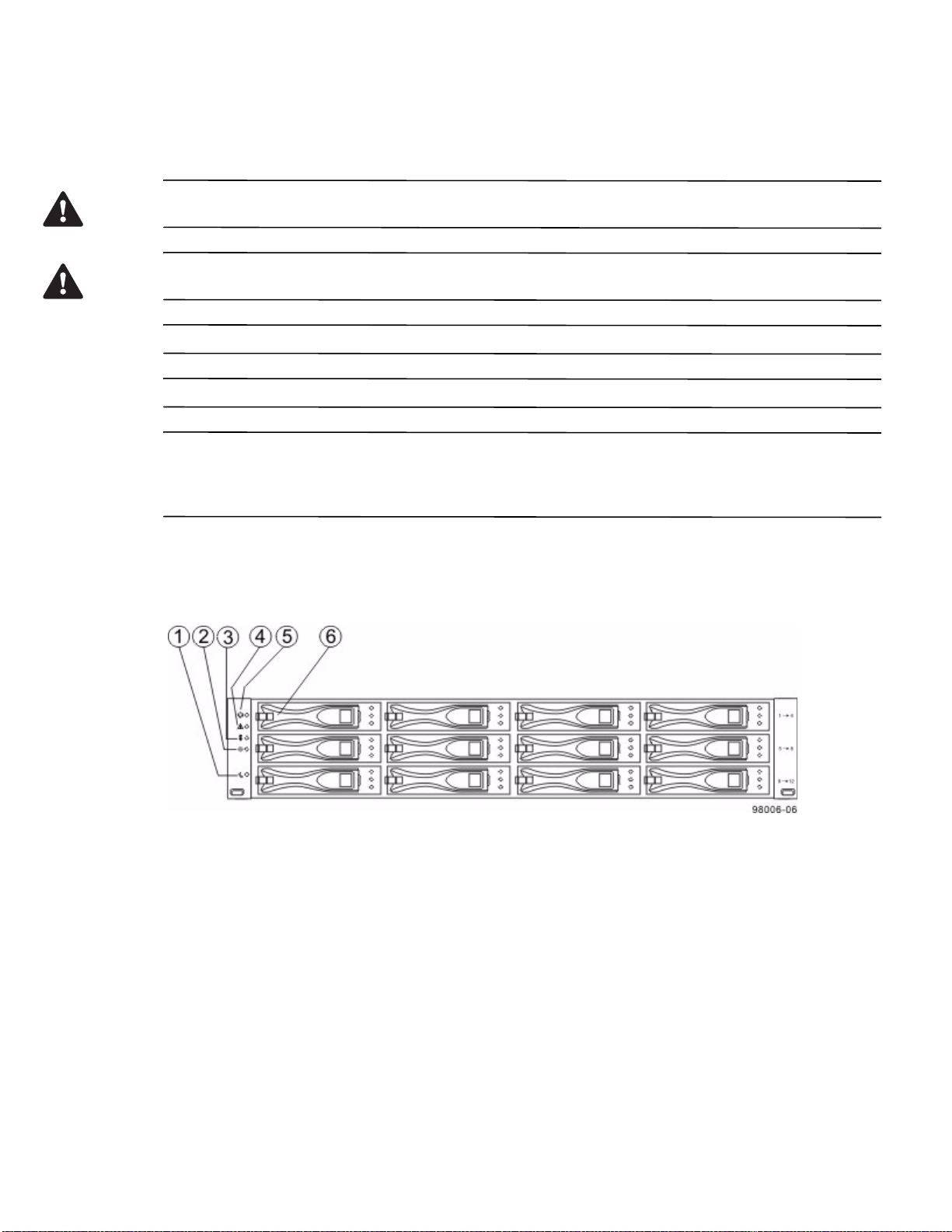
Figure 5 E2612 Controller-Drive Tray – Front View
1. End Cap Standby Power LED
2. End Cap Power LED
3. End Cap Over-Temperature LED
4. End Cap Service Action Required LED
5. End Cap Locate LED
6. Drive Canister
E2600 Controller-Drive Tray Installation Guide 11
Page 20
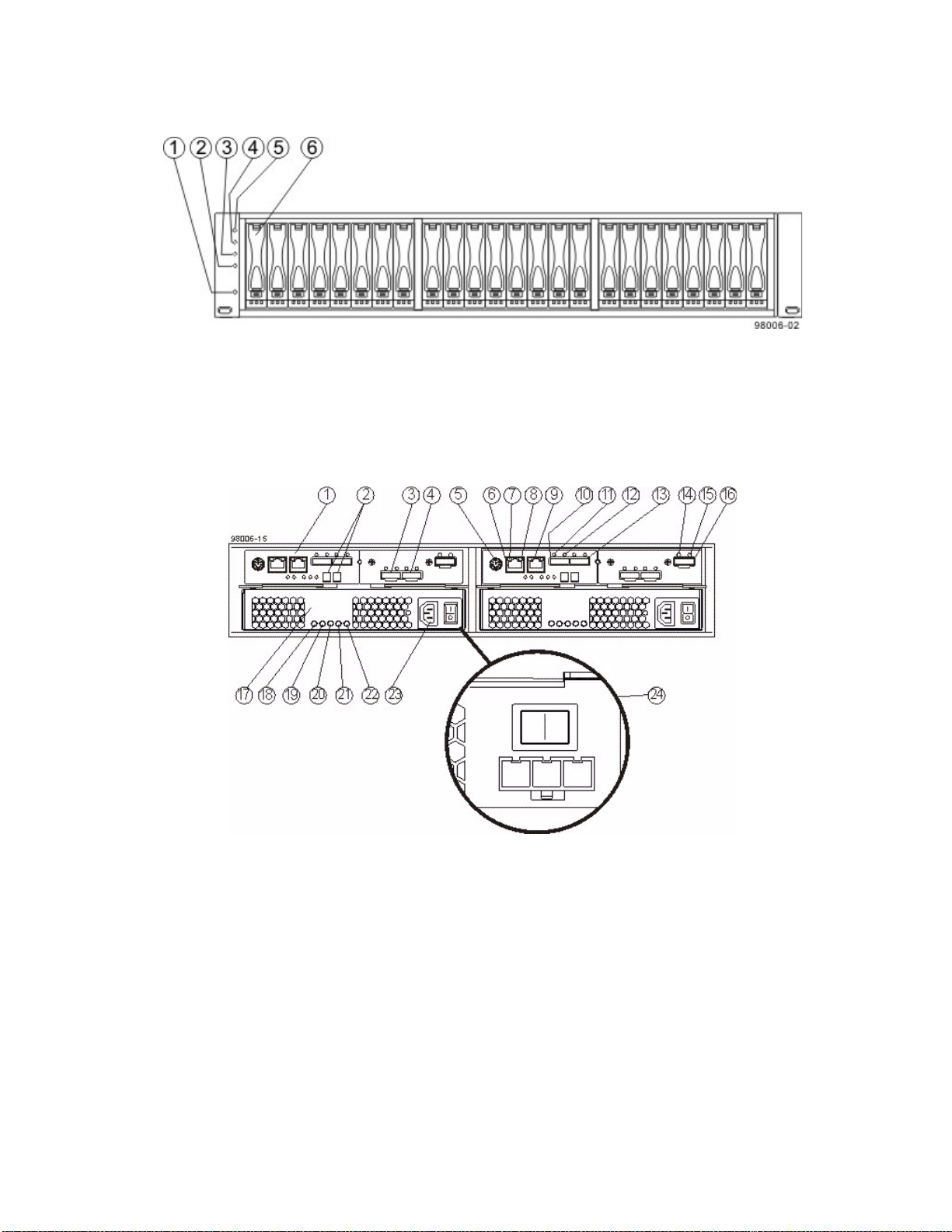
Figure 6 E2624 Controller-Drive Tray – Front View
1. End Cap Standby Power LED
2. End Cap Power LED
3. End Cap Over-Temperature LED
4. End Cap Service Action Required LED
5. End Cap Locate LED
6. Drive Canister
Figure 7 E2612 or E2624 Duplex Configuration– Rear View
1. Controller A Canister
2. Seven-Segment Display
3. Host Interface Card Connector 1
4. Host Interface Card Connector 2
5. Serial Connector
6. Ethernet Connector 1
7. Ethernet Link Active LED
8. Ethernet Link Rate LED
9. Ethernet Connector 2
10. Host SFF-8088 Connector 2 (Native)
11. Host Link 2 Fault LED
12. Host Link 2 Active LED
13. Base Host SFF-8088 Connector 1
12 E2600 Controller-Drive Tray Installation Guide
Page 21
14. ESM Expansion Fault LED
15. ESM Expansion Active LED
16. Expansion SFF-8088 Port Connector
17. Power-Fan Canister
18. Standby Power LED
19. Power-Fan DC Power LED
20. Power-Fan Service Action Allowed LED
21. Power-Fan Service Action Required LED
22. Power-Fan AC Power LED
23. Power-Fan AC Power Connector and Switch
24. Power-Fan DC Power Connector and Switch
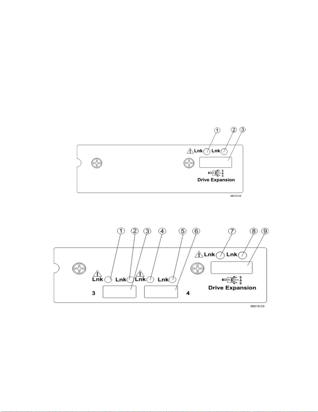
Figure 8 E2612 or E2624 Right-Rear Subplate with No Host Interface Card
1. ESM Expansion Fault LED
2. ESM Expansion Active LED
3. Expansion SFF-8088 Port Connector
Figure 9 E2612 or E2624 Right-Rear Subplate with a SAS Host Interface Card
1. Host Interface Card Link 3 Up LED
2. Host Interface Card Link 3 Active LED
3. SFF-8088 Host Interface Card Connector 3
4. Host Interface Card Link 4 Up LED
5. Host Interface Card Link 4 Active LED
6. SFF-8088 Host Interface Card Connector 4
7. ESM Expansion Fault LED
8. ESM Expansion Active LED
9. Expansion SFF-8088 Port Connector
E2600 Controller-Drive Tray Installation Guide 13
Page 22
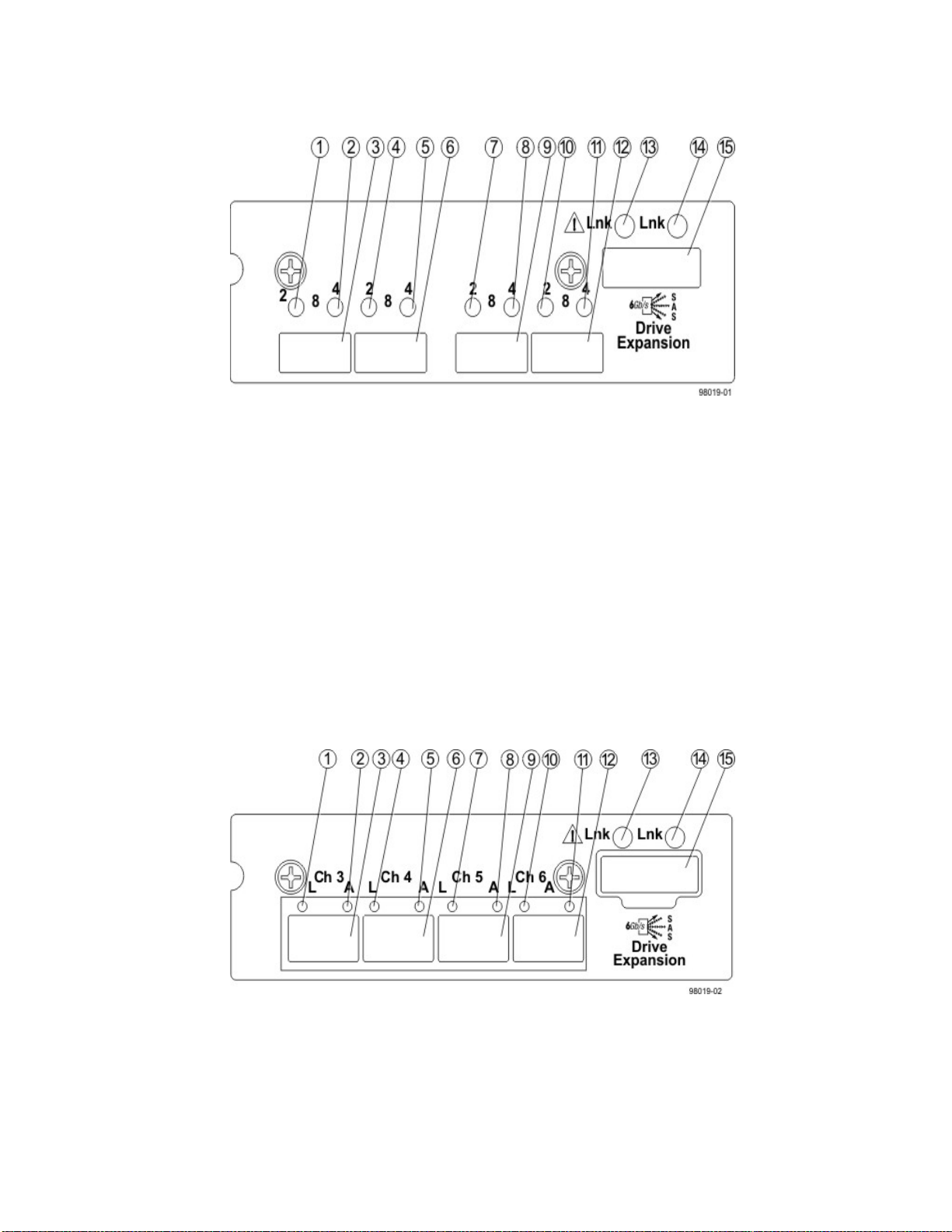
Figure 10 E2612 or E2624 Right-Rear Subplate with an FC Host Interface Card
1. Host Interface Card Link 3 Up LED
2. Host Interface Card Link 3 Active LED
3. FC Host Interface Card Connector 3
4. Host Interface Card Link 4 Up LED
5. Host Interface Card Link 4 Active LED
6. FC Host Interface Card Connector 4
7. Host Interface Card Link 5 Up LED
8. Host Interface Card Link 5 Active LED
9. FC Host Interface Card Connector 5
10. Host Interface Card Link 6 Up LED
11. Host Interface Card Link 6 Active LED
12. FC Host Interface Card Connector 6
13. ESM Expansion Fault LED
14. ESM Expansion Active LED
15. Expansion SFF-8088 Port Connector
Figure 11 E2612 or E2624 Right-Rear Subplate with a 1-Gb iSCSI Host Interface Card
1. Host Interface Card Link 3 Up LED
2. Host Interface Card Link 3 Active LED
3. iSCSI Host Interface Card Connector 3
4. Host Interface Card Link 4 Up LED
5. Host Interface Card Link 4 Active LED
6. iSCSI Host Interface Card Connector 4
14 E2600 Controller-Drive Tray Installation Guide
Page 23
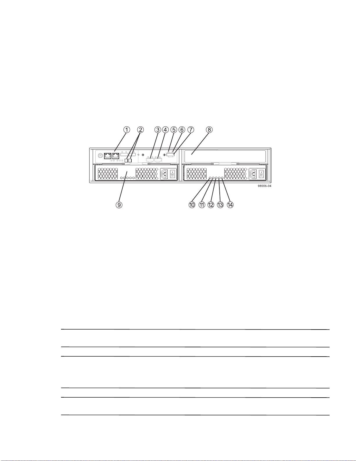
7. Host Interface Card Link 5 Up LED
8. Host Interface Card Link 5 Active LED
9. iSCSI Host Interface Card Connector 5
10. Host Interface Card Link 6 Up LED
11. Host Interface Card Link 6 Active LED
12. iSCSI Host Interface Card Connector 6
13. ESM Expansion Fault LED
14. ESM Expansion Active LED
15. Expansion SFF-8088 Port Connector
Figure 12 E2612 or E2624 Controller-Drive Tray Simplex Configuration – Rear View
1. Controller A Canister
2. Seven-Segment Display
3. Host Interface Card Connector 1
4. Host Interface Card Connector 2
5. ESM Expansion Fault LED
6. ESM Expansion Active LED
7. Expansion Port SFF-8088 Connector
8. Controller Air Blocker
9. Power-Fan A Canister (optional)
10. Standby Power LED
11. Power-Fan DC Power LED
12. Power-Fan Service Action Allowed LED
13. Power-Fan Service Action Required LED
14. Power-Fan AC Power LED
ATTENTION Possible equipment damage – You must use the supported drives in the drive tray to ensure proper
performance. For information about supported drives, contact a Technical Support representative.
ATTENTION Risk of equipment malfunction – To avoid exceeding the functional and environmental limits,
install only drives that have been provided or approved by the original manufacturer. Not all controller-drive trays
are shipped with pre-populated drives. System integrators, resellers, system administrators, or users of the
controller-drive tray can install the drives.
NOTE In a simplex configuration, the Controller Air Blocker must be kept in place to ensure proper air flow to the
components within the canister.
E2600 Controller-Drive Tray Installation Guide 15
Page 24
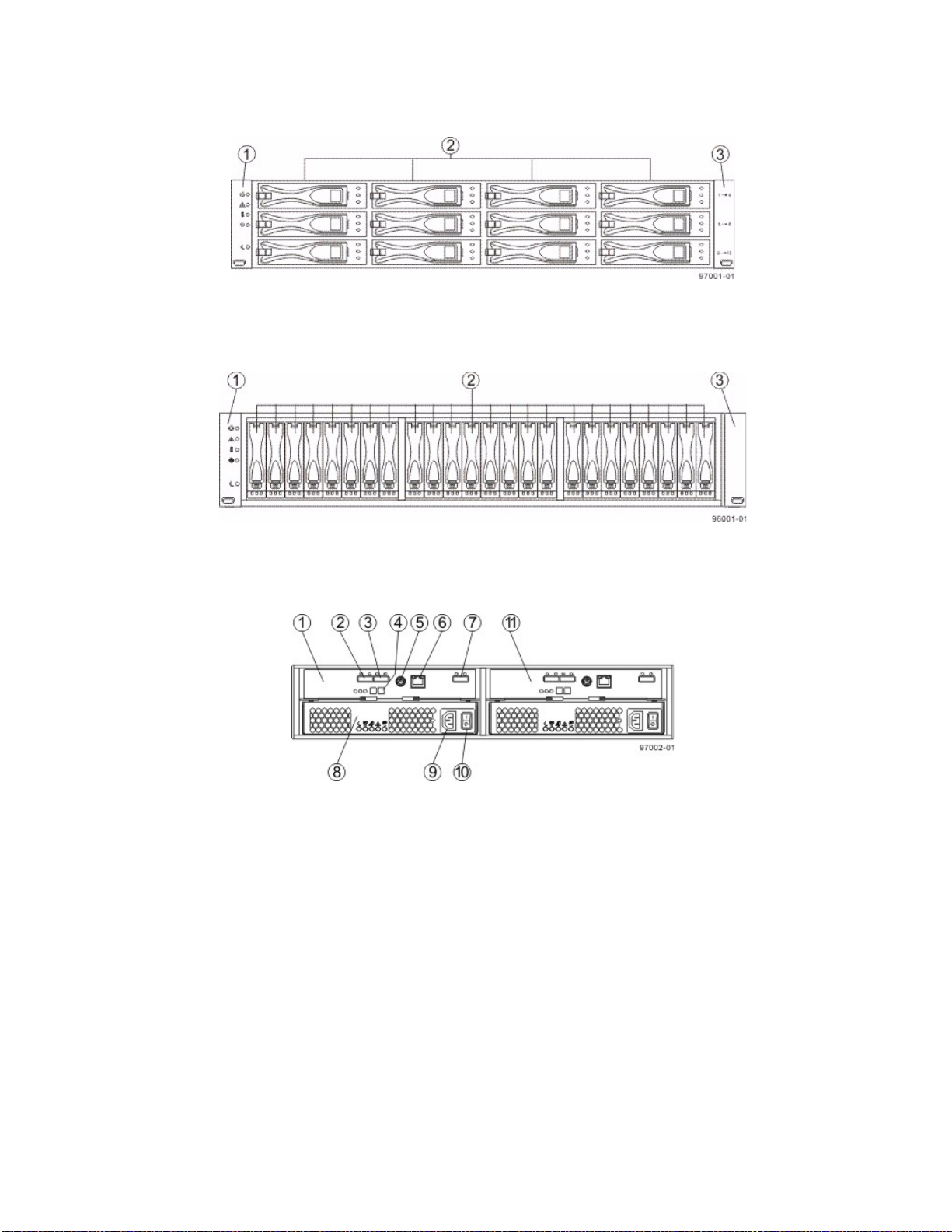
Figure 13 DE1600 Drive Tray – Front View
1. Left End Cap (Has the Drive Tray LEDs)
2. Drives
3. Right End Cap
Figure 14 DE5600 Drive Tray – Front View
1. Left End Cap (Has the Drive Tray LEDs)
2. Drives
3. Right End Cap
Figure 15 DE1600 Drive Tray or DE5600 Drive Tray with AC Power Option – Rear View
1. ESM A Canister
2. Host Connector 1
3. Host Connector 2
4. Seven-Segment Display Indicators
5. Serial Connector
6. Ethernet Connector
7. Expansion Port SFF-8088 Connector
8. Power-Fan Canister
9. Power Connector
10. Power Switch
11. ESM B Canister
16 E2600 Controller-Drive Tray Installation Guide
Page 25
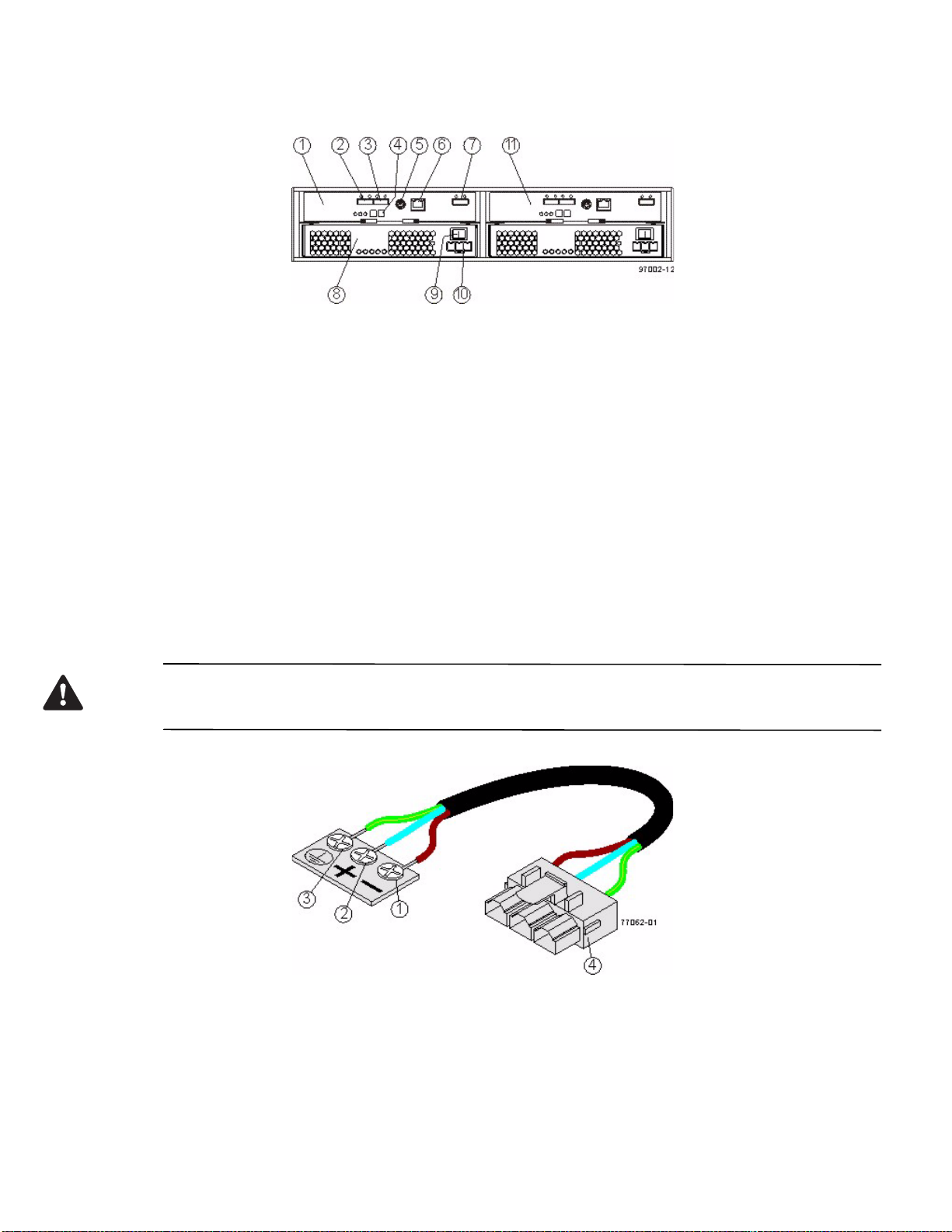
Figure 16 DE1600 Drive Tray or DE5600 Drive Tray with DC Power Option – Rear View
1. ESM A Canister
2. Host Connector 1
3. Host Connector 2
4. Seven-Segment Display Indicators
5. Serial Connector
6. Ethernet Connector
7. Expansion Port SFF-8088 Connector
8. Power-Fan Canister
9. Power Connector
10. Power Switch
11. ESM B Canister
You can order an optional DC power supply connection and connector cables for the drive tray. A qualified service
person is required to make the DC power connection per NEC and CEC guidelines. A two-pole 30-amp
circuit breaker is required between the DC power source and the drive tray for over-current and short-circuit
protection. Before turning off any power switches on a DC-powered drive tray, you must disconnect the two-pole
30-amp circuit breaker.
WARNING (W12) Risk of electrical shock – This unit has more than one power source. To remove all power from
the unit, all DC MAINS must be disconnected by removing all power conn
ectors (item 4 below) from the power
supplies.
1. Supply (Negative), Brown Wire, -48 VDC
2. Return (Positive), Blue Wire
3. Ground, Green/Yellow Wire
4. DC Power Connector
E2600 Controller-Drive Tray Installation Guide 17
Page 26
Things to Know – Taking a Quick Glance at the Hardware in a E2660
Controller-Drive Tray Configuration
WARNING (W14) Risk of bodily injury – A qualified service person is required to make the DC power
connection according to NEC and CEC guidelines.
CAUTION (C05) Electrical grounding hazard – This equipment is designed to permit the connection of the DC
supply circuit to the earthing conductor at the equipment.
NOTE To maintain a uniform airflow across all drive drawers, the controller-drive tray must be configured with a
minimum of 20 drives. Slots 1, 4, 7, and 10 in the front row of each of the five drive drawers must have a drive
installed in these locations.
NOTE iSCSI host ports do not support the Data Assurance (DA) premium feature.
ATTENTION Possible data loss – If you remove all Fibre Channel Host Interface Cards (HICs) from a storage
array and replace them with HICs of a different network protocol (such as iSCSI or SAS), you must first deactivate
the Remote Volume Mirroring (RVM) premium feature if it is activated. If you do not deactivate RVM before
removing the Fibre Channel HICs, your system will lose data access and data loss may occur.
The top of the controller-drive tray is the side with labels.
The configuration of the host ports might appear different on your system depending on which host interface
card configuration is installed.
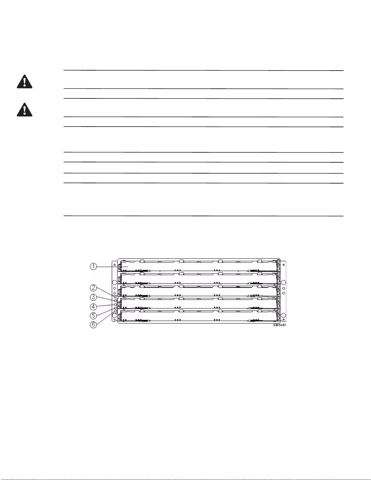
Figure 17 E2660 Controller-Drive Tray – Front View
1. Drive Drawer
2. End Cap Locate LED
3. End Cap Service Action Required LED
4. End Cap Over-Temperature LED
5. End Cap Power LED
6. End Cap Standby Power LED
18 E2600 Controller-Drive Tray Installation Guide
Page 27
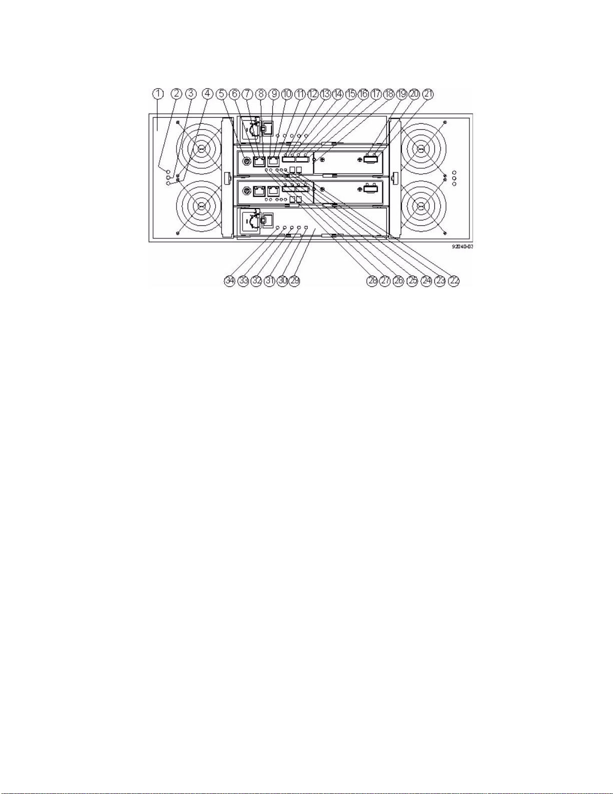
Figure 18 E2660 Controller-Drive Tray Duplex Configuration – Rear View
1. Fan Canister
2. Fan Canister Power LED
3. Fan Canister Service Action Required LED
4. Fan Canister Service Action Allowed LED
5. Serial Connector (PS2 to DB9 connector required)
6. Ethernet Link 1 Active LED
7. Ethernet Connector 1
8. Ethernet Link 1 Rate LED
9. Ethernet Link 2 Active LED
10. Ethernet Connector 2
11. Ethernet Link 2 Rate LED
12. Host Link 2 Fault LED
13. Base Host SFF-8088 Connector 2
14. Host Link 2 Active LED
15. Host Link 1 Fault LED
16. Host Link 1 Active LED
17. Base Host SFF-8088 Connector 1
18. Controller A Canister
19. ESM Expansion Fault LED
20. ESM Expansion Active LED
21. Expansion SFF-8088 Port Connector
22. Second Seven-Segment Display Field
23. First Seven-Segment Display Field
24. Cache Active LED
25. Controller A Service Ac
26. Controller A Service Action Allo
27. Battery Service Action Required LED
28. Battery Charging LED
29. Power Canister
30. Power Canister AC Power LED
31. Power Canister Service Action Required LED
Required LED
tion
wed LED
E2600 Controller-Drive Tray Installation Guide 19
Page 28
32. Power Canister Service Action Allowed LED
33. Power Canister DC Power LED
34. Power Canister Standby Power LED
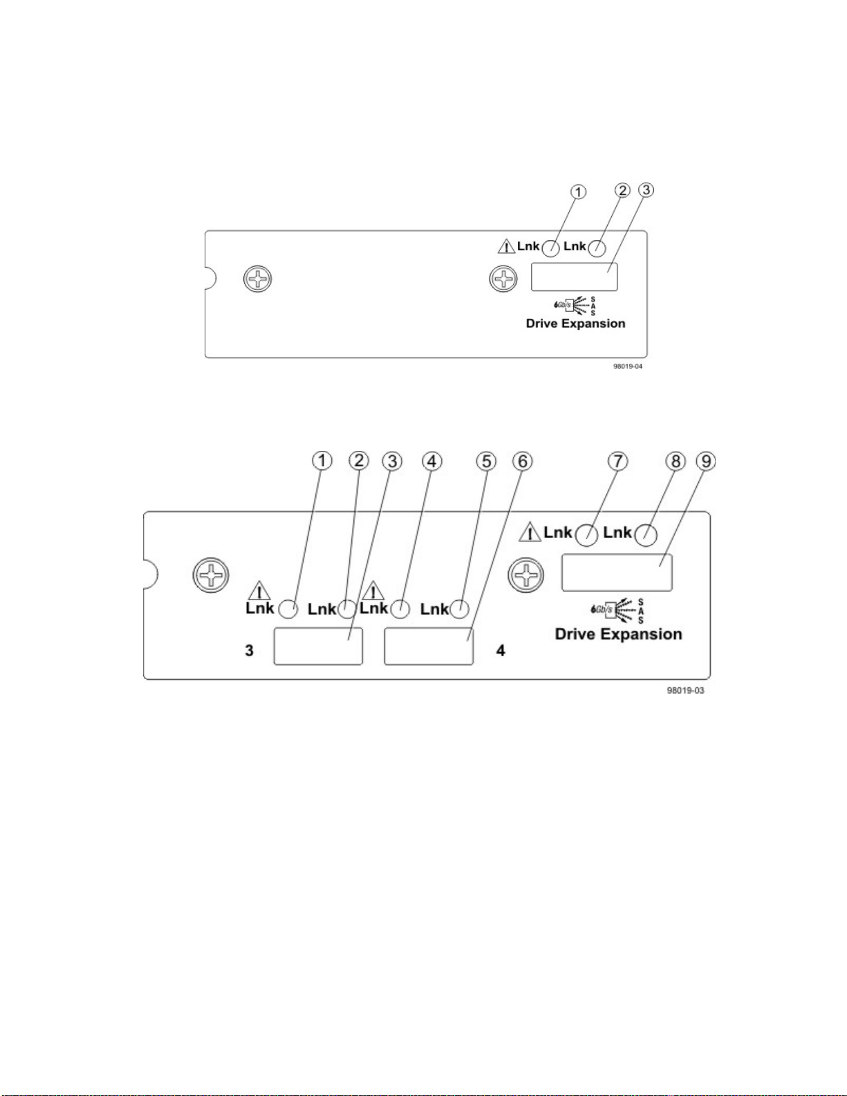
Figure 19 E2660 Right-Rear Subplate with No Host Interface Card
1. ESM Expansion Fault LED
2. ESM Expansion Active LED
3. Expansion SFF-8088 Port Connector
Figure 20 E2660 Right-Rear Subplate with a SAS Host Interface Card
1. Host Interface Card Link 3 Up LED
2. Host Interface Card Link 3 Active LED
3. SFF-8088 Host Interface Card Connector 3
4. Host Interface Card Link 4 Up LED
5. Host Interface Card Link 4 Active LED
6. SFF-8088 Host Interface Card Connector 4
7. ESM Expansion Fault LED
8. ESM Expansion Active LED
9. Expansion SFF-8088 Port Connector
20 E2600 Controller-Drive Tray Installation Guide
Page 29
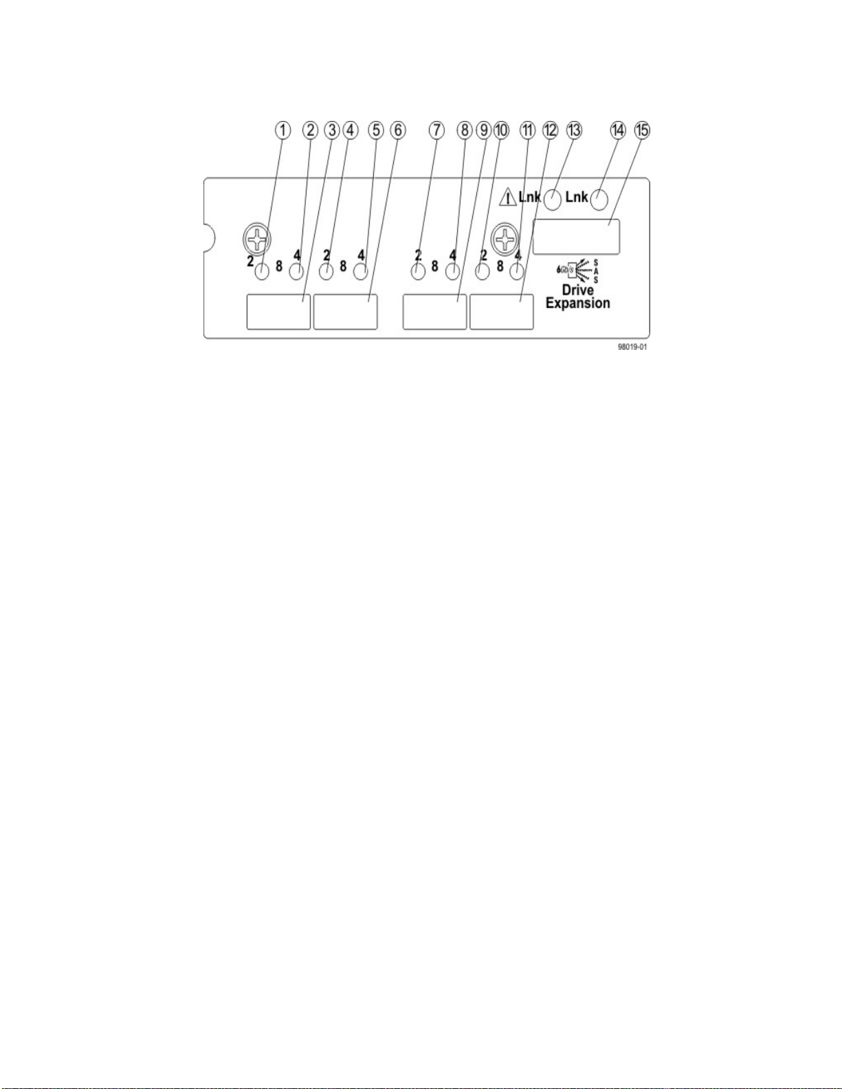
Figure 21 E2660 Right-Rear Subplate with an FC Host Interface Card
1. Host Interface Card Link 3 Up LED
2. Host Interface Card Link 3 Active LED
3. FC Host Interface Card Connector 3
4. Host Interface Card Link 4 Up LED
5. Host Interface Card Link 4 Active LED
6. FC Host Interface Card Connector 4
7. Host Interface Card Link 5 Up LED
8. Host Interface Card Link 5 Active LED
9. FC Host Interface Card Connector 5
10. Host Interface Card Link 6 Up LED
11. Host Interface Card Link 6 Active LED
12. FC Host Interface Card Connector 6
13. ESM Expansion Fault LED
14. ESM Expansion Active LED
15. Expansion SFF-8088 Port Connector
E2600 Controller-Drive Tray Installation Guide 21
Page 30
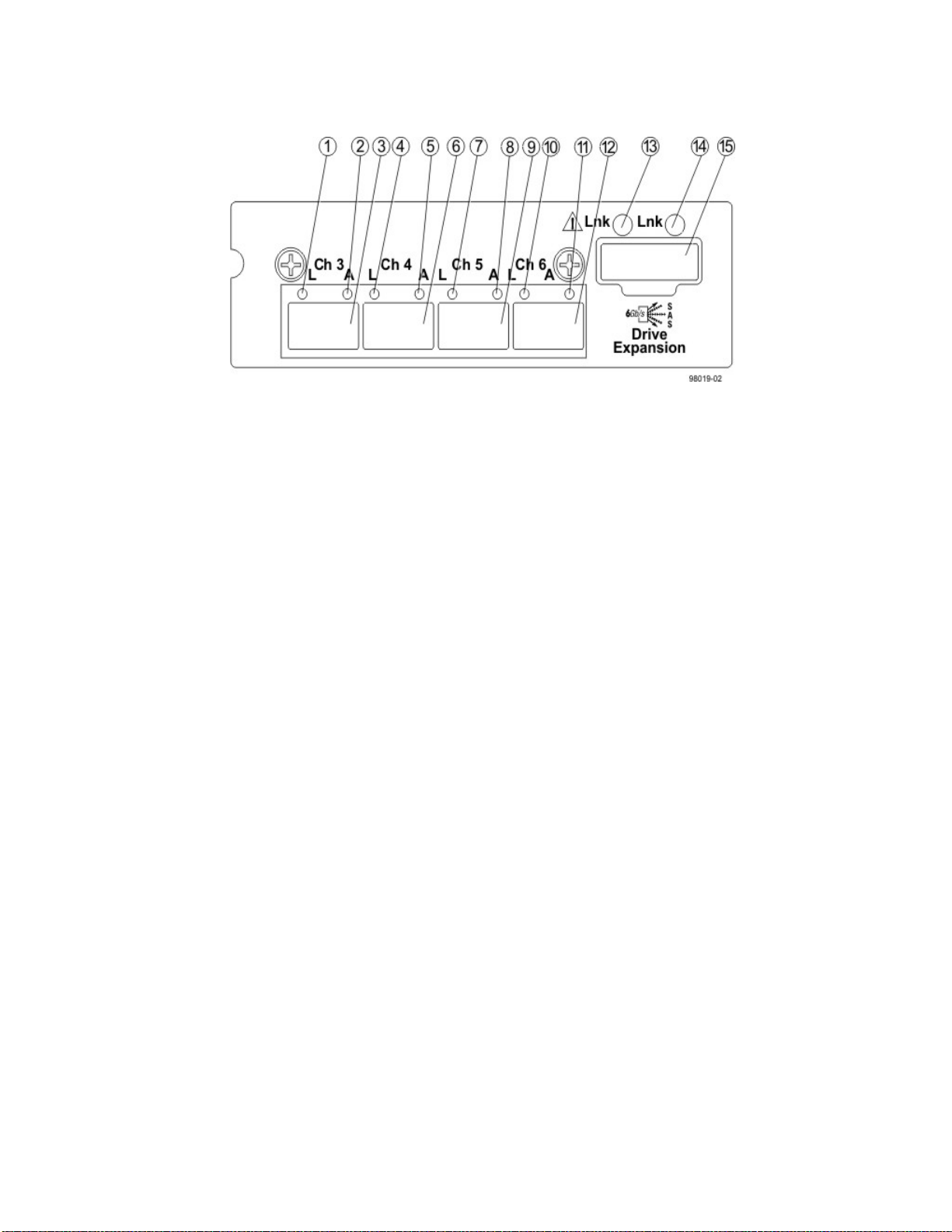
Figure 22 E2660 Right-Rear Subplate with a 1-Gb iSCSI Host Interface Card
1. Host Interface Card Link 3 Up LED
2. Host Interface Card Link 3 Active LED
3. iSCSI Host Interface Card Connector 3
4. Host Interface Card Link 4 Up LED
5. Host Interface Card Link 4 Active LED
6. iSCSI Host Interface Card Connector 4
7. Host Interface Card Link 5 Up LED
8. Host Interface Card Link 5 Active LED
9. iSCSI Host Interface Card Connector 5
10. Host Interface Card Link 6 Up LED
11. Host Interface Card Link 6 Active LED
12. iSCSI Host Interface Card Connector 6
13. ESM Expansion Fault LED
14. ESM Expansion Active LED
15. Expansion SFF-8088 Port Connector
22 E2600 Controller-Drive Tray Installation Guide
Page 31
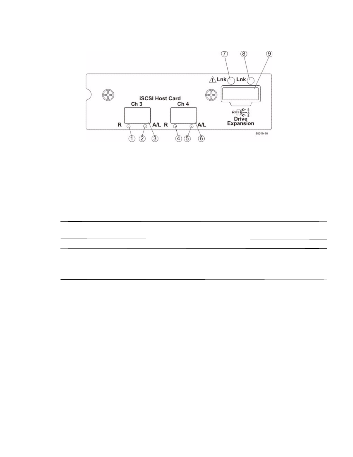
Figure 23 E2660 Right-Rear Subplate with a 10-Gb iSCSI Host Interface Card
1. Host Interface Card Link 3 Up LED
2. Host Interface Card Link 3 Active LED
3. iSCSI Host Interface Card Connector 3
4. Host Interface Card Link 4 Up LED
5. Host Interface Card Link 4 Active LED
6. iSCSI Host Interface Card Connector 4
7. ESM Expansion Fault LED
8. ESM Expansion Active LED
9. Expansion SFF-8088 Port Connector
ATTENTION Possible equipment damage – You must use the supported drives in the drive tray to ensure proper
performance. For information on supported drives, contact a Technical Support representative.
ATTENTION Risk of equipment malfunction – To avoid exceeding the functional and environmental limits,
install only drives that have been provided or approved by the original manufacturer. Not all controller-drive trays
are shipped with prepopulated drives. System integrators, resellers, system administrators, or users of the
controller-drive tray can install the drives.
For Additional Information on the E2600 Controller-Drive Tray Configuration
Refer to the Storage System Site Preparation Guide on the SANtricity ES Storage Manager Installation DVD for
information about the installation requirements of the various E2600 storage array components.
E2600 Controller-Drive Tray Installation Guide 23
Page 32

24 E2600 Controller-Drive Tray Installation Guide
Page 33
Step 2 - Installing and Configuring the Switches
Things to Know – Switches, Routers, and SFPs
NOTE Most of the switches, as shipped from the vendor, require an update to their firmware to work correctly with
the storage array.
Depending on the configuration of your storage array, you might use Fibre Channel switches, iSCSI switches, or
SAS switches.
The SFPs in Table 1 0 on page 27 apply only if you are using Fibre Channel network protocols.
The switches in the following table are certified for use with an E2600 storage array and an E2660 storage array,
which both use SANtricity ES Storage Manager Version 10.83.
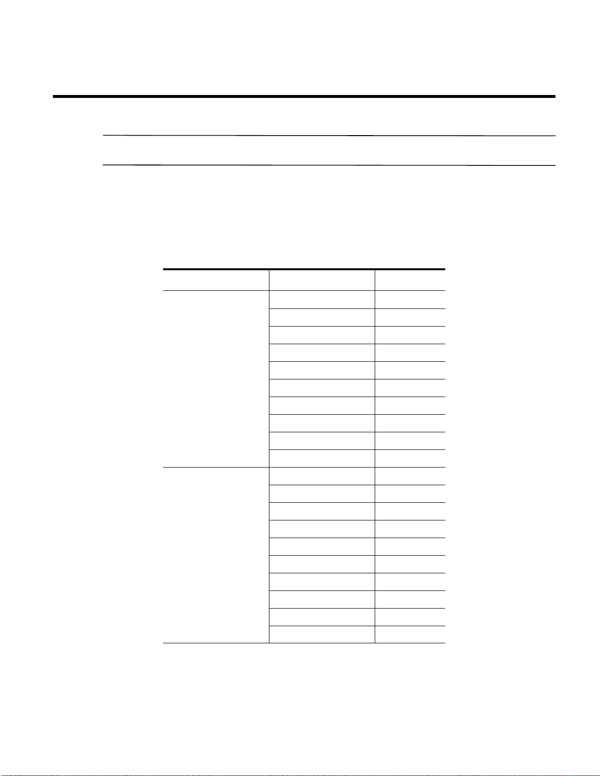
Table 7 Supported Fibre Channel Switches and Routers
Vendor Model Data Rate
Brocade 200E 4 Gb
4100 4 Gb
48000 4 Gb
5000 4 Gb
300 8 Gb
5100 8 Gb
5300 8 Gb
7500 4 Gb
7800 8 Gb
DCX 8 Gb
Cisco 9506 4 Gb
9509 4 Gb
9216 4 Gb
9216i 4 Gb
9120 4 Gb
914x 4 Gb
9513 4 Gb, 8 Gb
9020 4 Gb
9222i 8 Gb
9134 4 Gb
E2600 Controller-Drive Tray Installation Guide 25
Page 34
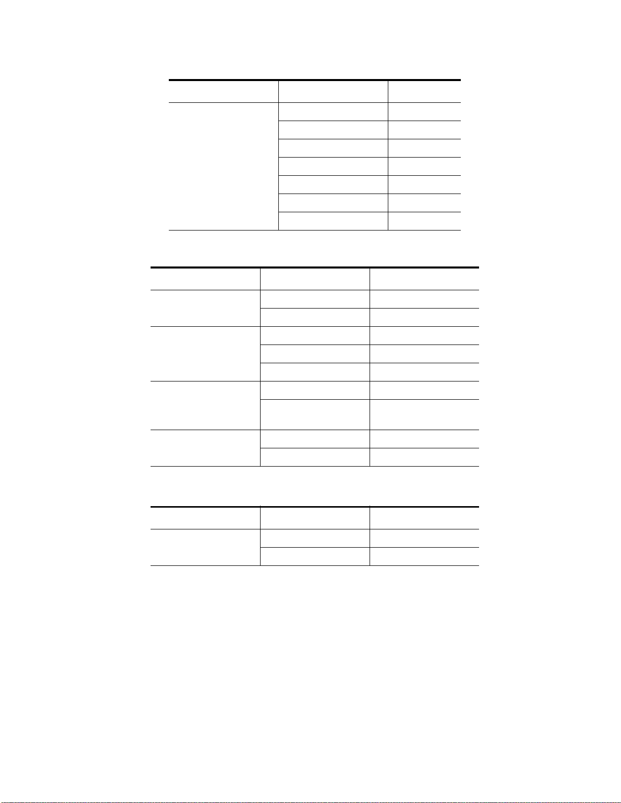
Vendor Model Data Rate
QLogic SANbox5200 4 Gb
Table 8 Supported iSCSI Switches
Vendor Model Data Rate/Connection
Brocade 8000 10 GB / Optical
Cisco Catalyst 3560 1 GB / RJ45
SANbox3600 4 Gb
SANbox3800 8 Gb
SANbox5600 8 Gb
SANbox5800 8 Gb
SANbox9000 8 Gb
6142 8 Gb
Turbiron 10 GB / Optical
Catalyst 3750G-24TS 1 GB / RJ45
Nexus 5000 10 GB / Optical
Dell 8024 10 GB / Copper (RJ45)
8024F 10 GB / Ethernet / SFP
Plus (24-port)
PowerConnect 5324 1 GB / RJ45
6024 1 GB / RJ45
Table 9 Supported SAS Switches
Vendor Model Version/Data Rate
LSI 6160 SAS 2.0 / 6 GB (16-port)
6160 SAS 2.0 / 6 GB
If required, make the appropriate configuration changes for each switch that is connected to the storage array.
Refer to the switch’s documentation for information about how to install the switch and how to use the
configuration utilities that are supplied with the switch.
26 E2600 Controller-Drive Tray Installation Guide
Page 35
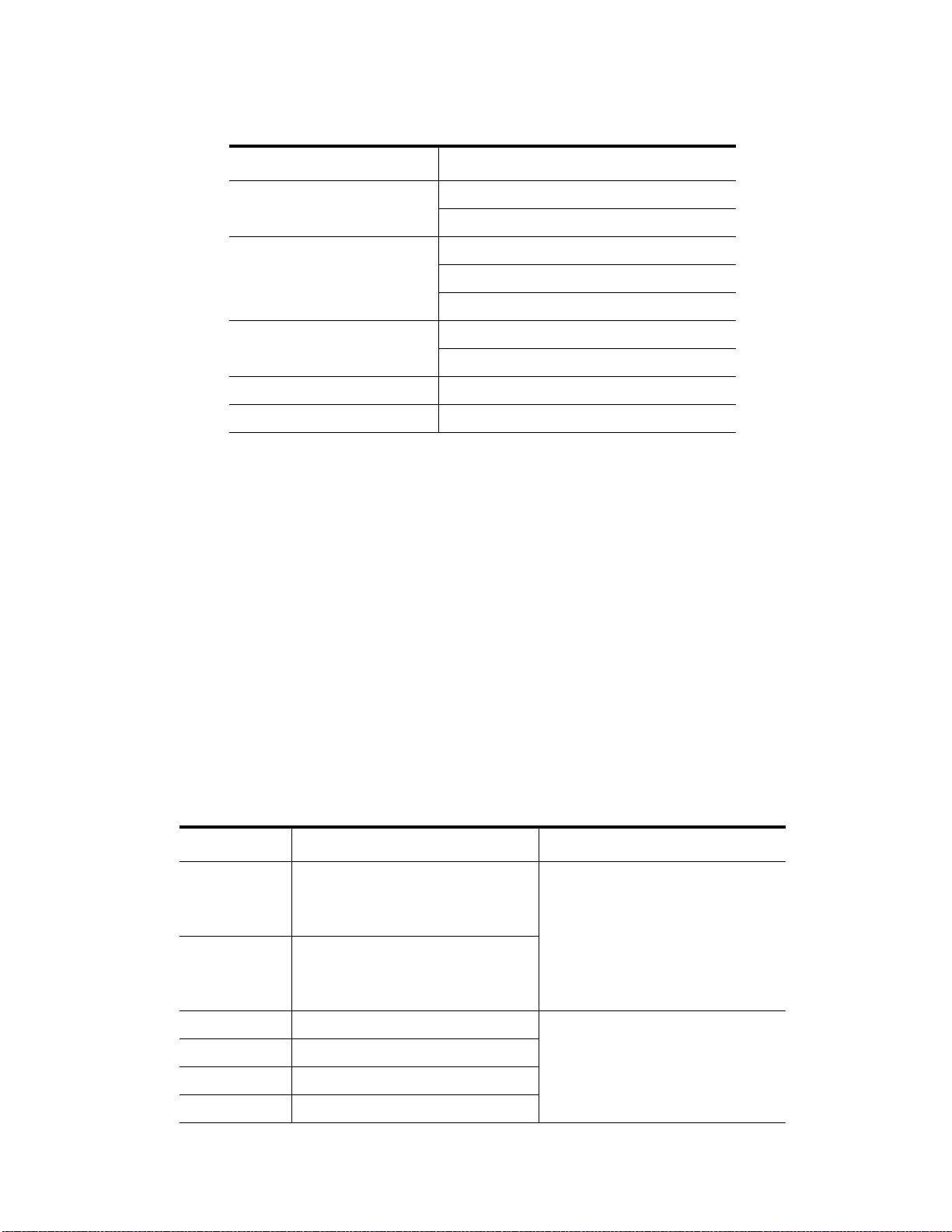
Table 10 NetApp Supported SFPs
Vendor Version/Data Rate
Ava go 8G
10G
Finisar 1G
8G
10G
JDSU 8G
10G
Molex 8G
Opnext 10G
Refer to your Technical Support representative for the latest information about new switches that are tested and
certified to work with various hardware and software combinations.
Procedure – Installing and Configuring Switches
1. Install your switch according to the vendor’s documentation.
2. Refer to your Technical Support representative to obtain this information:
— The latest hardware compatibility information
— The models of the switches that are supported
— The firmware requirements and the software requirements for the switches
3. Update the switch’s firmware by accessing it from the applicable switch vendor’s
website.
This update might require that you cycle power to the switch.
4. Find your switch in the following table to see whether you need to make further configuration changes. Use
your switch
Table 11 Supported Switch Vendors and Required Configuration Changes
’s configuration utility to make the changes.
Switch Vendor Configuration Changes Required? Next Step
Brocade Yes
Change the In-Order Delivery (IOD)
option to ON.
Make the change, and go to
“Installing the Host Bus Adapters for
the E2600 Controller-Drive Tray” on
page 29.
Cisco Yes
Change the In-Order Delivery (IOD)
option to ON.
LSI No “Installing the Host Bus Adapters for
McData No
the E2600 Controller-Drive Tray” on
page 29.
QLogic No
PowerConnect No
E2600 Controller-Drive Tray Installation Guide 27
Page 36

28 E2600 Controller-Drive Tray Installation Guide
Page 37

Step 3 - Installing the Host Bus Adapters for the E2600
Controller-Drive Tray
Key Terms
HBA host port
The physical and electrical interface on the host bus adapter (HBA) that provides for the connection between the
host and the controller. Most HBAs will have either one or two host ports. The HBA has a unique World Wide
Identifier (WWID) and each HBA host port has a unique WWID.
HBA host port world wide name
A 16-character unique name that is provided for each port on the host bus adapter (HBA).
host bus adapter (HBA)
A physical board that resides in the host. The HBA provides for data transfer between the host and the controllers in
the storage array over the I/O host interface. Each HBA contains one or more physical ports.
Things to Know – Host Bus Adapters and Ethernet Network Interface Cards
The E2600 controller-drive tray supports dual 6-Gb/s SAS host connections and optional host interface cards
(HICs) for dual 6-Gb/s SAS, four 1-Gb/s iSCSI, two 10-Gb iSCSI, and four 8-Gb/s FC connections. The
connections on a host must match the type (SAS HBAs for SAS, FC HBAs for FC, or iSCSI HBAs or Ethernet
network interface cards [NICs] for iSCSI) of the HICs to which you connect them. For the best performance,
HBAs for SAS and FC connections should support the highest data rate supported by the HICs to which they
connect.
For maximum hardware redundancy, you must install a minimum of two HBAs (for either SAS or FC host
connections) or two NICs or iSCSI HBAs (for iSCSI host connections) in each host. Using both ports of a
dual-port HBA or a dual-port NIC provides two paths to the storage array but does not ensure redundancy if an
HBA or a NIC fails.
NOTE Consult your Technical Support representative to obtain information about the supported models of the
HBAs and their requirements to make sure you have an acceptable configuration.
Most of the HBAs, as shipped from the vendor, require updated firmware and software drivers to work
correctly with the storage array. For information about the updates, refer to the website of the storage vendor to
obtain certified versions.
Procedure – Installing Host Bus Adapters
1. Check with your Technical Support representative to make sure you have an acceptable configuration. Before
installing an HBA, you must have the following information:
— The latest hardware compatibility information
— The models of the HBAs that are supported
— The firmware requirements and the software requirements for the HBAs
2. Install your HBA according to the vendor documentation.
E2600 Controller-Drive Tray Installation Guide 29
Page 38
NOTE If your operating system is Windows Server 2008 Server Core, you might have additional installation
requirements. Refer to the Microsoft Developers Network (MSDN) fo
r more information about Windows Server
2008 Server Core. You can access these resources from www.microsoft.com.
3. Install the latest version of the firmware for the HBA. You can find the latest version of the firmware for the
HBA at the storage vendor website.
NOTE The remaining steps are general steps to obtain the HBA host port world wide name from the HBA BIOS
utility. If you have installed the host context agent on all of your hosts, you do not need to perform these steps. If
you are performing these steps, the actual prompts and screens vary depending on the vendor that provides the HBA.
Also, some HBA have software utilities that you can use to obtain the world wide name for the port instead of using
the BIOS utility. If a configuration uses a Fibre Channel switch, you can find the World Wide Port Name of each
port of the HBA from the name server of the switch.
4. Reboot or start your host.
5. While your host is booting, look for the prompt to access the HBA BIOS utility.
6. Select each HBA to view its HBA host port world wide name.
7. Record the following information for each host and for each HBA connected to the storage array:
— The name of each host
— The HBAs in each host
— The HBA host port world wide name of each port on the HBA
The following table shows examples of the host and HBA information that you must record.
Table 12 Examples of HBA Host Port World Wide Names
Host Name Associated HBAs
HBA Host Port World
Wide Name
ICTENGINEERING Vendor x, Model y (dual port) 37:38:39:30:31:32:33:32
37:38:39:30:31:32:33:33
Vendor a, Model y (dual port) 42:38:39:30:31:32:33:42
42:38:39:30:31:32:33:44
ICTFINANCE Vendor a, Model b (single port) 57:38:39:30:31:32:33:52
Vendor x, Model b (single port) 57:38:39:30:31:32:33:53
30 E2600 Controller-Drive Tray Installation Guide
Page 39
Step 4 - Installing the E2600 Controller-Drive Tray
Things to Know – General Installation
The power supplies meet standard voltage requirements for both domestic and worldwide operation.
NOTE Make sure that the combined power requirements of your trays do not exceed the power capacity of your
cabinet.
Procedure – Installing the E2600 Controller-Drive Tray
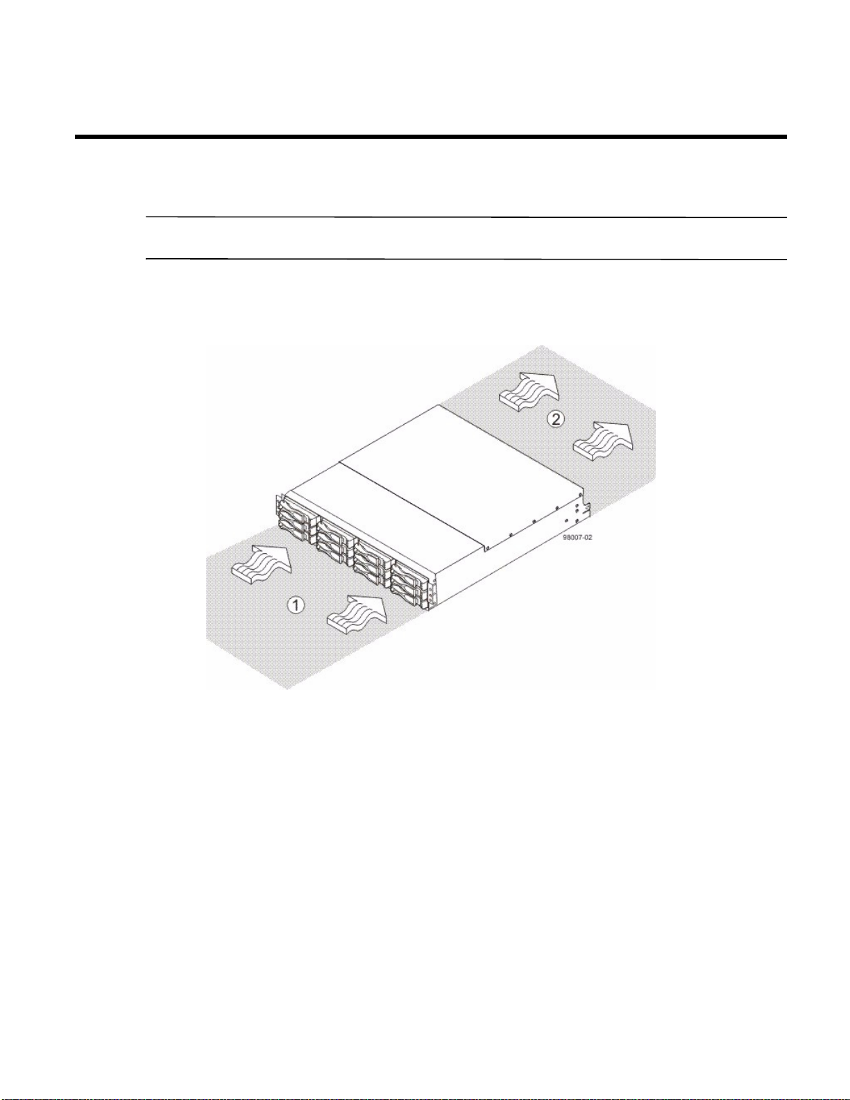
Figure 24 Airflow Direction Through and Clearance Requirements for the E2600 Controller-Drive Tray with 12
Drives
1. 76-cm (30-in.) clearance in front of the cabinet
2. 61-cm (24-in.) clearance behind the cabinet
E2600 Controller-Drive Tray Installation Guide 31
Page 40
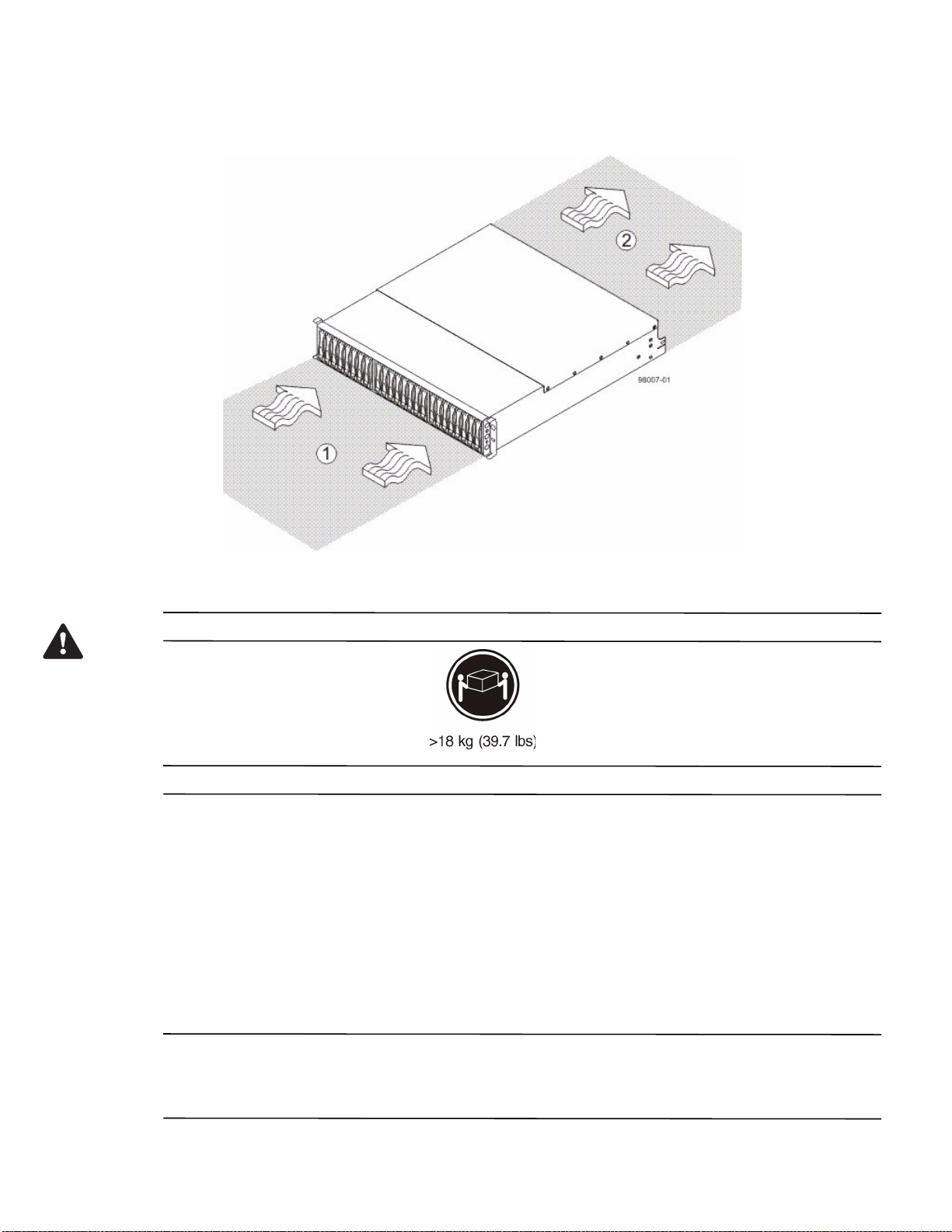
Figure 25 Airflow Direction Through and Clearance Requirements for the E2600 Controller-Drive Tray with 24
Drives
1. 76-cm (30-in.) clearance in front of the cabinet
2. 61-cm (24-in.) clearance behind the cabinet
WARNING (W08) Risk of bodily injury –
Two persons are required to safely lift the component.
1. Make sure that the cabinet is in the final location. Make sure that the cabinet installation site meets the
clearance requirements (see Figure 24 on page 31 and Figure 25).
2. Lower the feet on the cabinet, if required, to keep it from moving.
3. Install the mounting rails in the cabinet. For more information, refer to the installation instructions that are
included with your mounting rails.
— If you are installing the mounting rails above an existing tray, position the mounting rails directly above
the existing tray.
— If you are installing the mounting rails below an existing tray, allow 17.8-cm (7.00-in.) clearance below
the existing tray.
ATTENTION Risk of equipment malfunction – To avoid exceeding the functional and environmental limits,
install only drives that have been provided or approved by the original manufacturer. Not all controller-drive trays
are shipped with pre-populated drives. System integrators, resellers, system administrators, or users of the
controller-drive tray can install the drives.
32 E2600 Controller-Drive Tray Installation Guide
Page 41
NOTE Make sure that you place the controller-drive tray in the middle portion of the cabinet while allowing room
for drive trays to be placed above and below the controller-drive tray. As you add drive trays, position them below
and above the controller-drive tray, alternating so that the cabinet does not become top heavy.
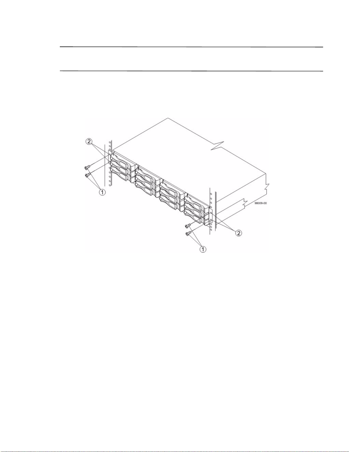
4. With the help of one other person, slide the rear of the controller-drive tray onto the mounting rails. Make sure
that the top mounting holes on the controller-drive tray align with the mounting rail holes of the cabinet (see
Figure 26 and Figure 27 on page 34).
The rear of the controller-drive tray slides into the slots on th
Figure 26 Securing the E2600 Controller-Drive Tray with 12 Drives to the Cabinet
1. Screws
2. Mounting Holes
e mounting rails.
E2600 Controller-Drive Tray Installation Guide 33
Page 42
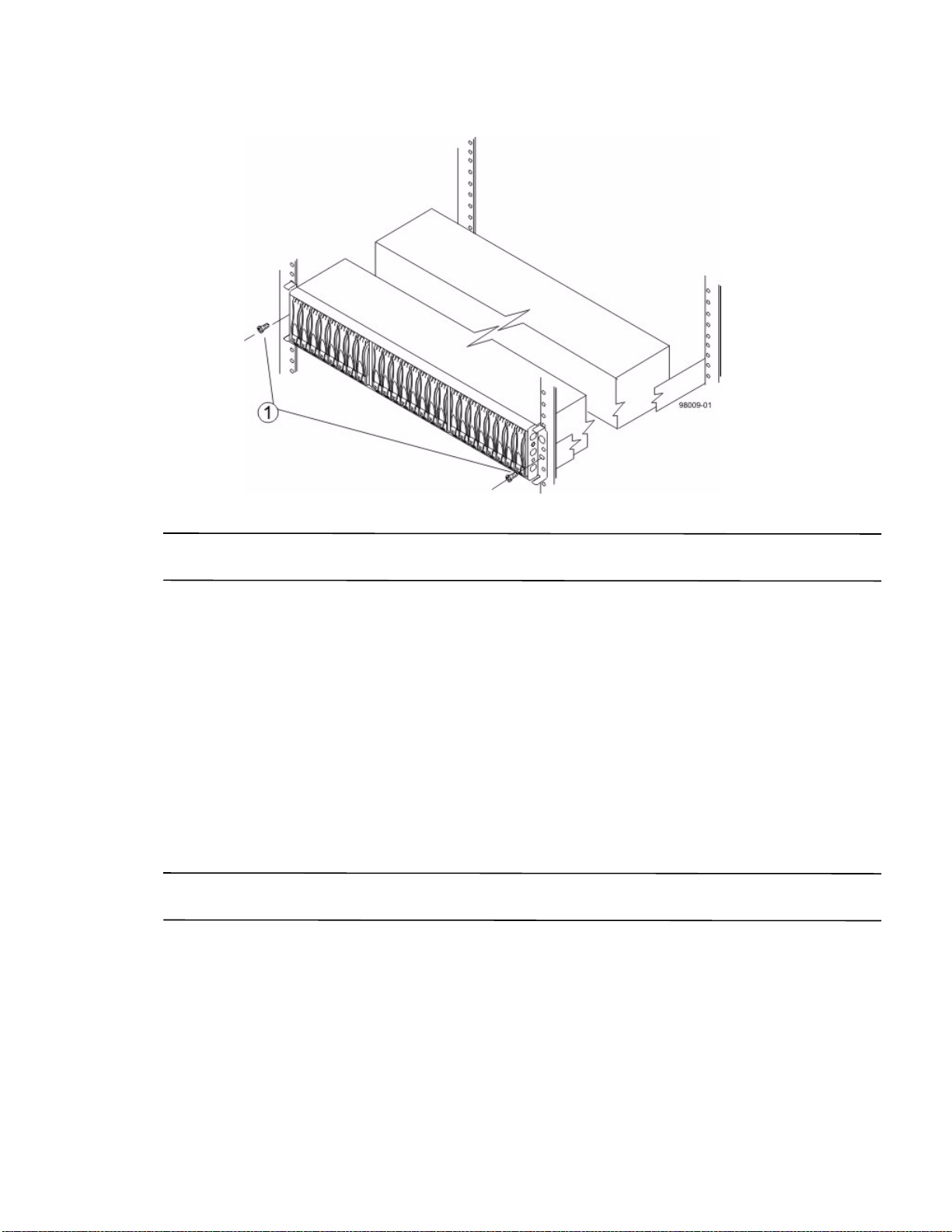
Figure 27 Securing the E2600 Controller-Drive Tray with 24 Drives to the Cabinet
1. Screws
NOTE The rear of the controller-drive tray contains two controllers. The top of the controller-drive tray is the side
with the labels.
5. Secure the screws in the top mounting holes and the bottom mounting holes on each side of the controller-drive
tray.
6. Secure the rear of the of the controller-drive tray to the cabinet by using two screws to attach the flanges on
each side at the rear of the controller-drive tray to the mounting rails.
7. Install the bezel on the front of the controller-drive tray.
8. Install the drive trays. Refer to Connecting the E2600 Controller-Drive Tray to the Drive Trays on page 81.
Procedure – Installing the E2660 Controller-Drive Tray
You can install the high-density, 6-Gb SAS SBB 2.0-compliant E2660 controller-drive tray into an
Industry-standard cabinet, provided it has a depth of 100 cm (40 in.).
A minimum depth of 76 cm (30 in.) between the front EIA support rails and the rear EIA support rails is required.
NOTE If you are mounting the E2660 controller-drive tray in a cabinet with square holes, use the eight shoulder
washers in the rail kit to align the screws in the holes (see step 4 on page 36 through step 7 on page 38).
34 E2600 Controller-Drive Tray Installation Guide
Page 43
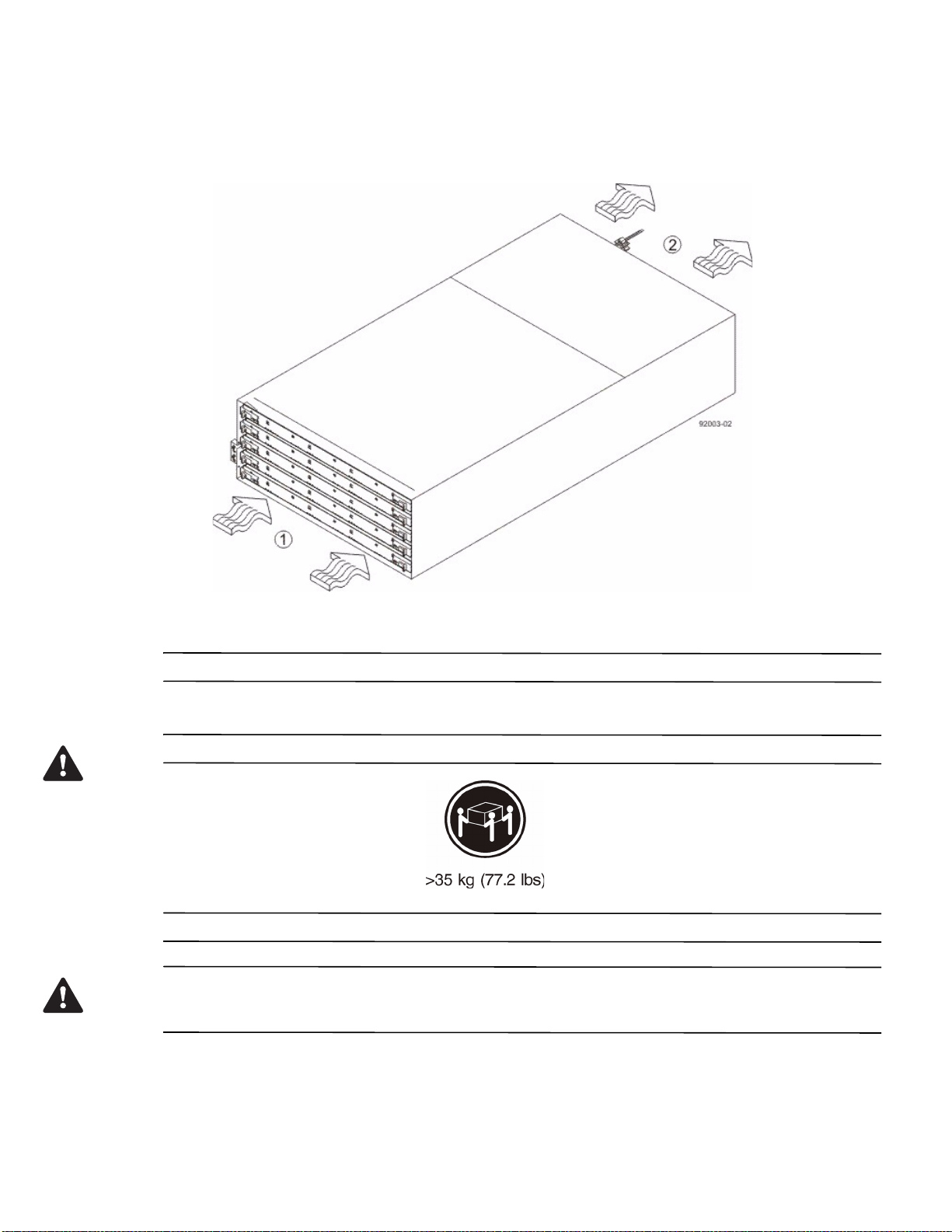
1. Make sure that the cabinet is in the final location. Make sure that you meet the clearance requirements shown
in the following figure.
Figure 28 Controller-Drive Tray Airflow and Clearance Requirements
1. 81 cm (32 in.) clearance in front of the cabinet
2. 61 cm (24 in.) clearance behind the cabinet
NOTE Fans pull air through the controller-drive tray from front to back across the drives.
2. Lower the feet on the cabinet to keep the cabinet from moving.
WARNING (W09) Risk of bodily injury –
Three persons are required to safely lift the component.
WARNING (W15) Risk of bodily injury – An empty tray weighs approximately 56.7 kg (125 lb). Three persons
are required to safely move an empty tray. If the tray is populated with components, a mechanized lift is required to
safely move the tray.
E2600 Controller-Drive Tray Installation Guide 35
Page 44
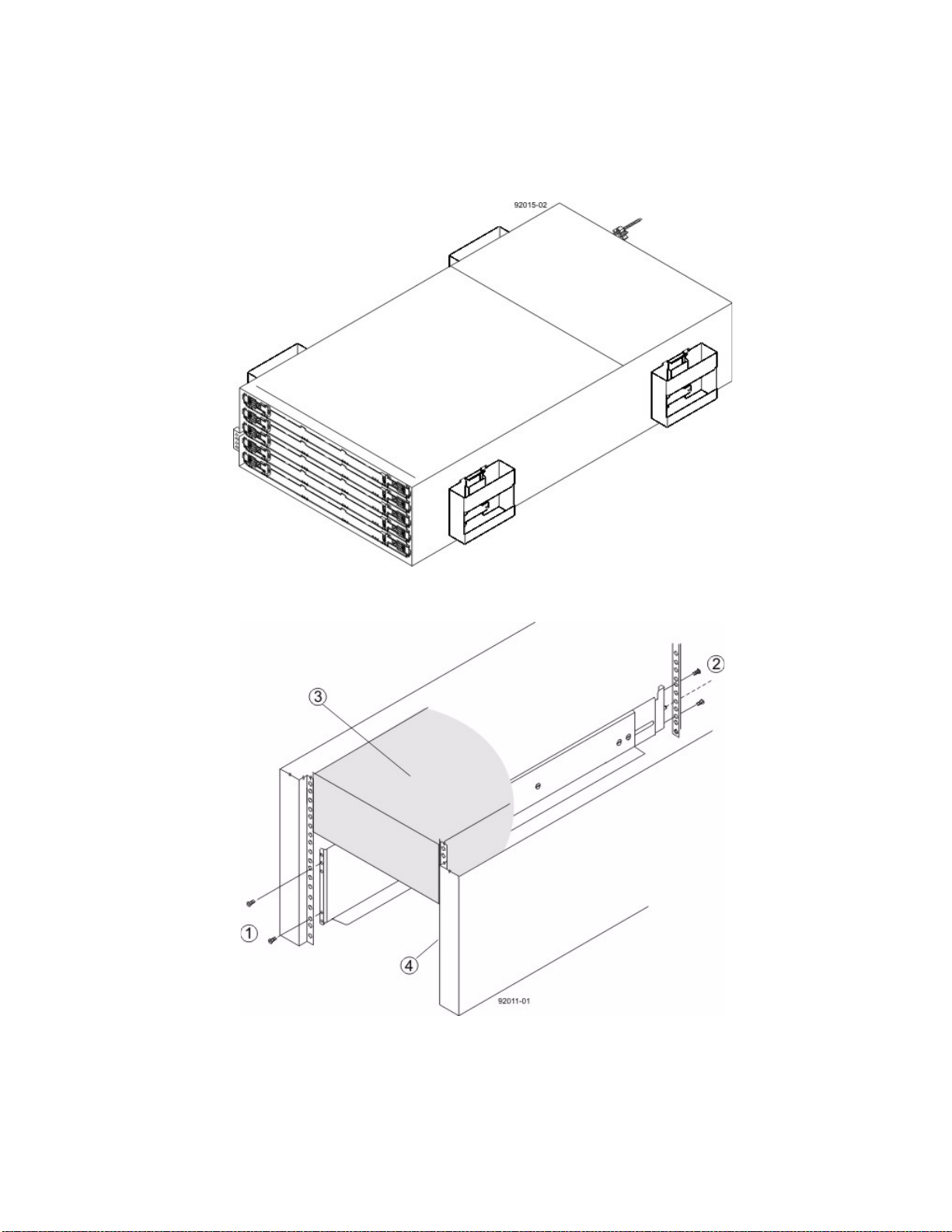
3. With the help of at least two other persons, remove the drive tray and all of the contents from the shipping
carton, using the four controller-drive tray handles (two to a side) as shown in the figure "E2660
Controller-Drive Tray with Controller-Drive Tray Handles (Two on Each Side)." Set the drive tray aside.
Figure 29 E2660 Controller-Drive Tray with Controller-Drive Tray Handles (Two on Each Side)
4. Position the mounting rails in the cabinet.
Figure 30 Positioning the Mounting Rails in the Cabinet
1. Screws for Securing the Mounting Rail to the Cabinet (Front)
2. Screws for Securing the Mounting Rail to the Cabinet (Rear)
3. Existing Tray
4. Industry Standard Cabinet
36 E2600 Controller-Drive Tray Installation Guide
Page 45
— If you are installing the mounting rails above an existing tray, position the mounting rails directly above
the controller-drive tray.
— If you are installing the mounting rails below an existing tray, allow 17.8-cm (7-in.) vertical clearance for
a E2660 controller-drive tray.
5. To attach the mounting rails to the cabinet, do one of
— If you are using the long fixed size mounting rails, go to step 6.
— If you are using the shorter adjustable mounting rails, go to step 7.
the following:
6. To attach the long mounting rails to the cabinet, perform these substeps:
a. M
ake sure that the adjustment screws on the mounting rail are loose so that the mounting rail can
extend or contract as needed.
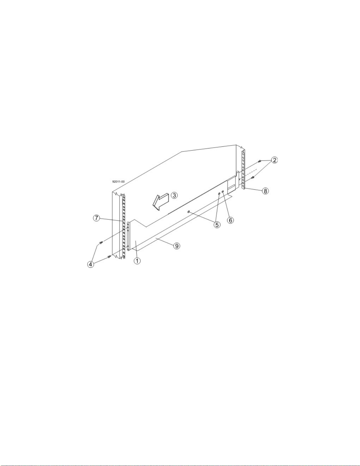
Figure 31 Attaching the Long Mounting Rails to the Cabinet
1. Front of the Mounting Rail
2. Two M5 Screws for the Rear EIA Support Rail
3. Front of the Cabinet
4. Two M5 Screws for the Front EIA Support Rail
5. Adjustable Rail Tightening Screws
6. Rear Hold-Down Screw
7. Cabinet Mounting Holes on the Front EIA Support Rail
8. Cabinet Mounting Holes on the Rear EIA Support Rail
9. Mounting Rail Lip
b. Remove the rear hold-down screw. It protrudes from the inside of the rail and prevents you from
sliding the drive tray onto the rails.
c. Place the mounting rail inside the cabinet, and extend the mounting rail until the flanges on the
mounting rail touch the inside of the cabinet.
d. Insert one M5 screw through the front of the cabinet, and screw it into the top captured nut in the
mounting rail.
e. Insert two M5 screws through the rear of the cabinet, and screw them into the captured nuts in the
rear flange in the mounting rail.
f. Tighten the adjustment screws on the mounting rail.
g. Repeat substep a through substep f to install the second mounting rail.
E2600 Controller-Drive Tray Installation Guide 37
Page 46
h. Insert one M5 screw through the front of the mounting rail. You use this screw to attach the
controller-drive tray to the cabinet.
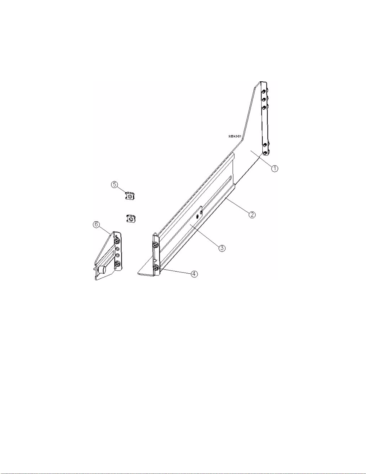
7. To attach the shorter, adjustable size mounting rails to the cabinet, perform these sets of substeps:
Figure 32 Short Adjustable Mounting Rail -- Left Side
1. Front of the Mounting Rail
2. Rear of the Mounting Rail
3. Rail Fix Bar
4. Two M5 Screws for the Front EIA Support Rail
5. Two Clips for the Front EIA Support Rail
6. Rear Bracket
a. Make sure that the adjustment screws on the mounting rail are loose so that the mounting rail can
extend or contract as needed (see the figure "Short Adjustable Mounting Rail -- Left Side").
b. Place the mounting rail inside the cabinet, and extend the mounting rail until the flanges on the
mounting rail touch the inside of the cabinet (see the figure "Short Adjustable Mounting Rail Attached
to the Cabinet" on page 39).
c. Insert one M5 screw through the front of the cabinet, and screw it into the top captured nut in the
mounting rail.
d. Insert two M5 screws through the rear of the cabinet, and screw them into the captured nuts in the
rear flange in the mounting rail.
e. Tighten the adjustment screws on the mounting rail.
f. Repeat substep a through substep e to install the second mounting rail.
38 E2600 Controller-Drive Tray Installation Guide
Page 47
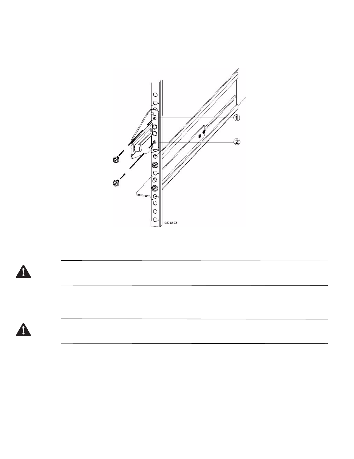
g. Insert one M5 screw through the front of the mounting rail. This screw attaches the drive tray to the
cabinet.
Figure 33 Short Adjustable Mounting Rail Attached to the Cabinet
1. Top Cabinet Mounting Hole on the Rear EIA Support Rail
2. Bottom Cabinet Mounting Hole on the Rear EIA Support Rail
8. Remove the bezel from the front of the drive tray.
WARNING (W15) Risk of bodily injury – An empty tray weighs approximately 56.7 kg (125 lb). Three persons
are required to safely move an empty tray. If the tray is populated with components, a mechanized lift is required to
safely move the tray.
9. With the help of at least two other persons, slide the rear of the controller-drive tray onto the mounting rails.
The controller-drive tray is correctly aligned when the mounting holes on the front flanges of the
controller-drive tray align with the mounting holes on the front of the mounting rails.
WARNING (W15) Risk of bodily injury – An empty tray weighs approximately 56.7 kg (125 lb). Three persons
are required to safely move an empty tray. If the tray is populated with components, a mechanized lift is required to
safely move the tray.
E2600 Controller-Drive Tray Installation Guide 39
Page 48
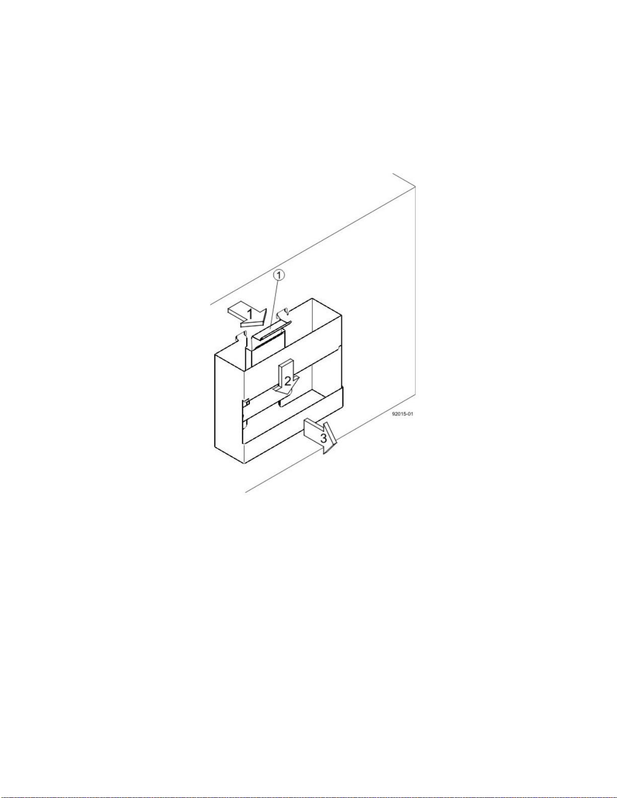
10. After the controller-drive tray is correctly aligned, remove the enclosure lift handles as shown in the figure
"Removing an Enclosure Lift Handle from the Controller-Drive Tray":
a. Use your thumb to unlatch and remove the rear enclosure lift handles (two to a side).
b. Use the front enclosure lift handles to slide the drive tray all the way into the cabinet.
c. After the drive tray is securely in the cabinet, use your thumb to unlatch and remove the front
enclosure lift handles (two to a side).
Figure 34 Removing an Enclosure Lift Handle from the Controller-Drive Tray
1. Pull the thumb latch away from the controller-drive tray to detach the hook.
2. Shift the handle down to release the other four hooks.
3. Move the handle away from the drive tray.
40 E2600 Controller-Drive Tray Installation Guide
Page 49
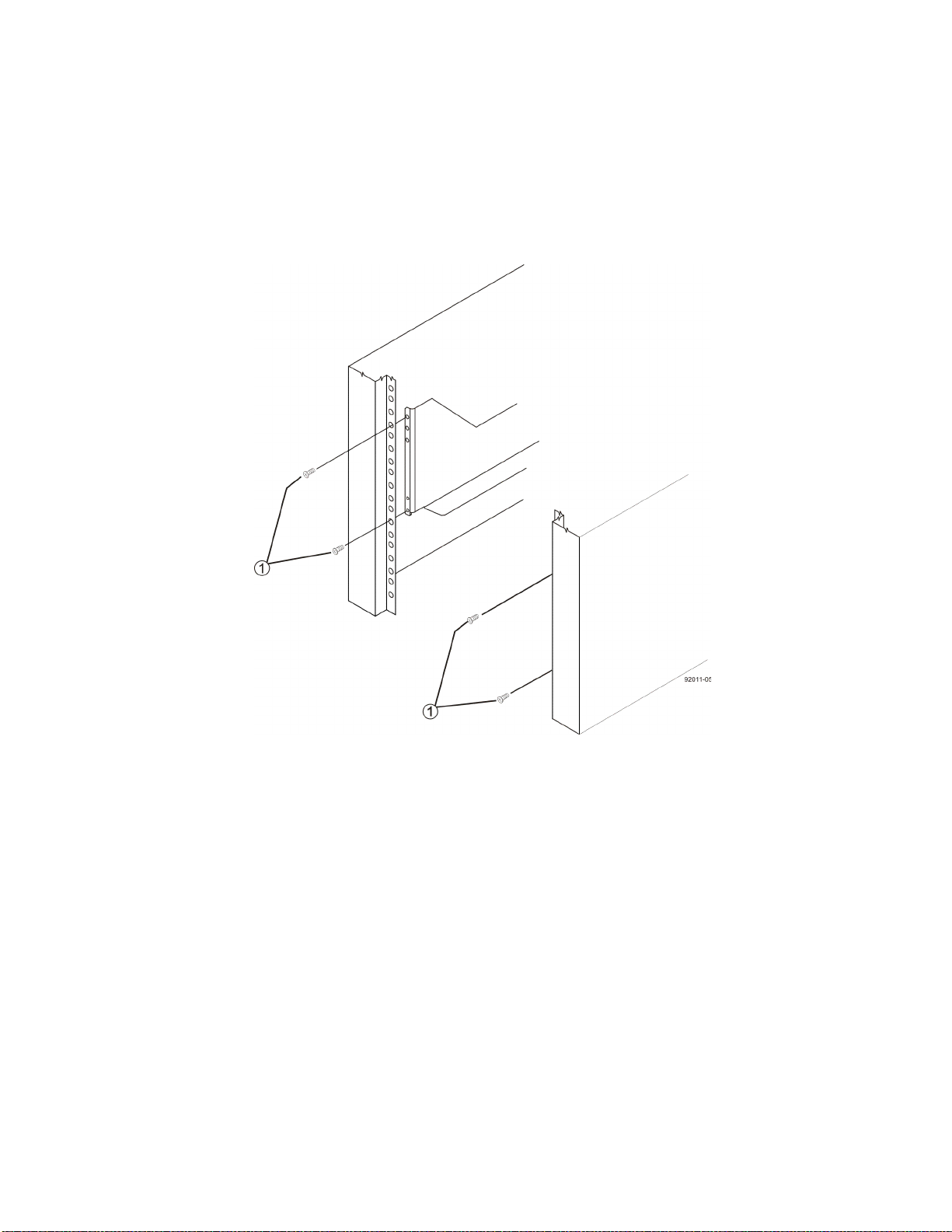
11. Secure the front of the controller-drive tray to the cabinet. Use the four screws to attach the flange on each side
of the front of the controller-drive tray to the mounting rails.
a. Insert two M5 screws through the bottom holes of a flange on the controller-drive tray so that the
screws go through the EIA support rail and engage the bottom captured nuts in the mounting rail.
Tighten the screws.
b. Repeat substep a for the second flange.
Figure 35 Attaching the Front of the Controller-Drive Tray
1. Four Screws for Securing the Front of the Controller-Drive Tray
E2600 Controller-Drive Tray Installation Guide 41
Page 50
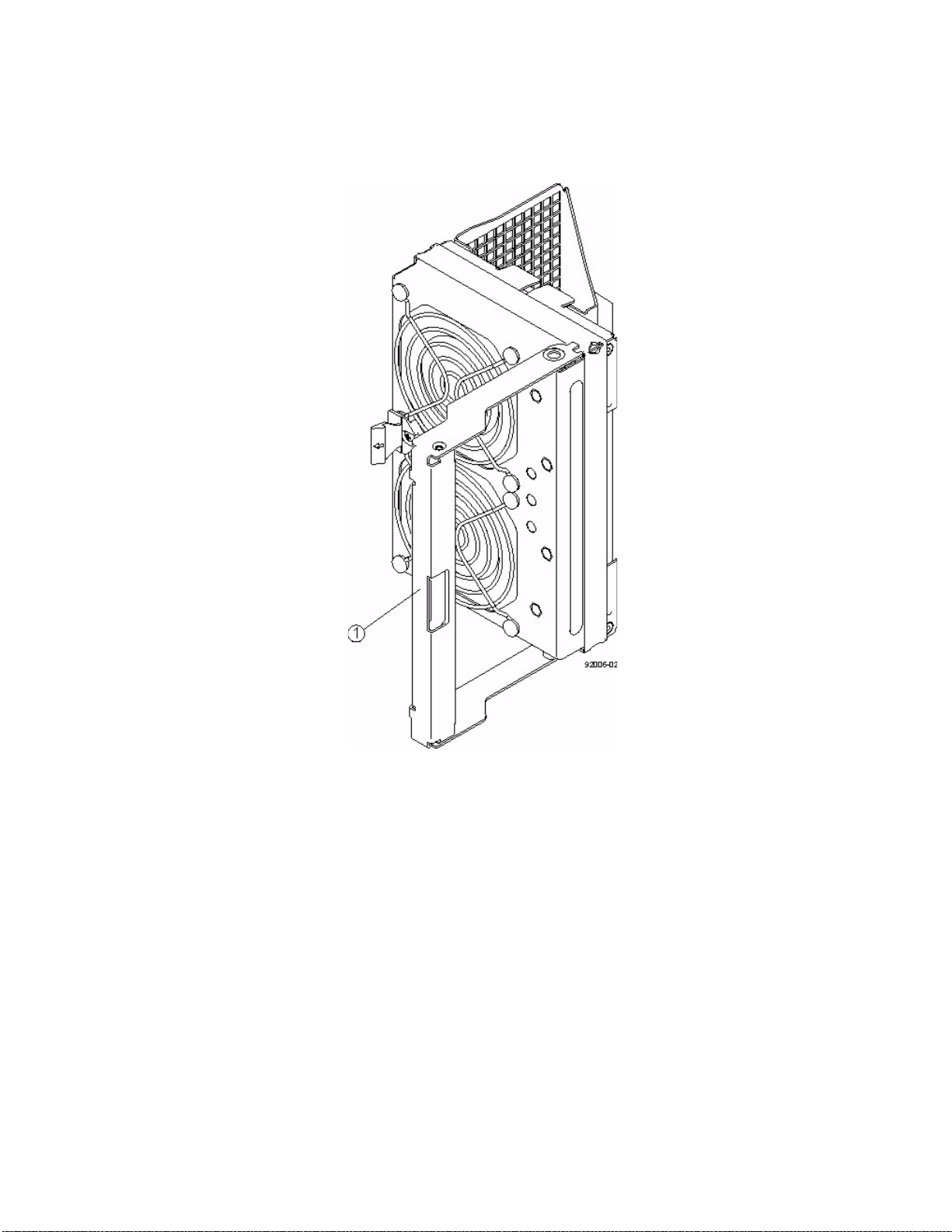
12. Remove the fan canister from the controller-drive tray by pressing on the tab holding the fan canister handle in
place, and then pulling the fan canister toward you.
Figure 36 Removing the Fan Canister from the Controller-Drive Tray
1. Fan Canister Handle
13. Use the fan canister handle to pull the fan canister out of the controller-drive tray.
42 E2600 Controller-Drive Tray Installation Guide
Page 51
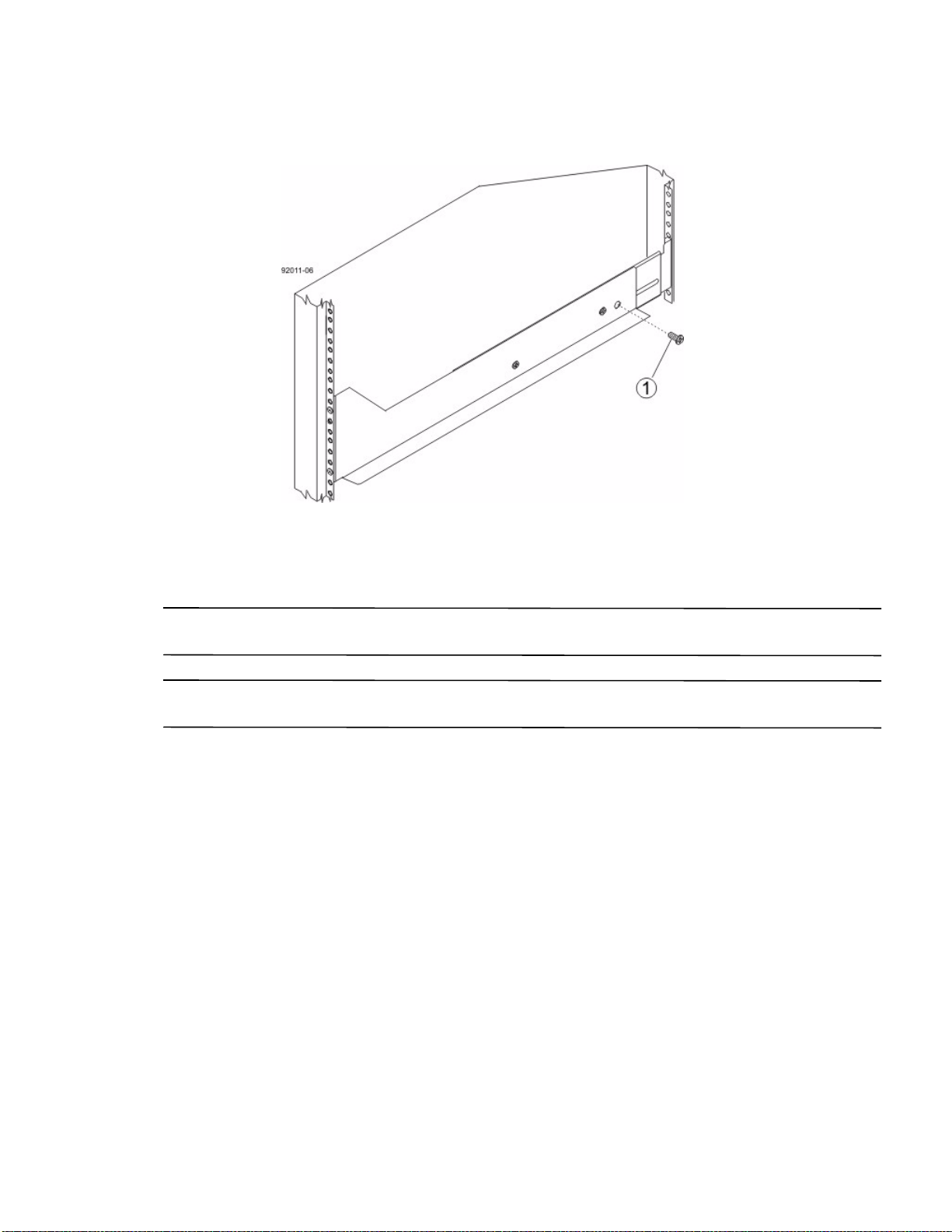
14. Secure the side of the controller-drive tray to the mounting rails by performing these substeps:
Figure 37 Securing the Controller-Drive Tray to the Rails
1. 10-32 Screw
a. Insert a 10-32 screw through the side sheet metal of the controller-drive tray into the captured nut on
the side of the mounting rail. Tighten the screws.
b. Repeat substep a for the other side.
NOTE After the controller-drive tray is installed, there should be seven screws on each side (right and left) of the
cabinet.
NOTE Make sure that each drive drawer in the controller-drive tray is securely fastened to ensure proper air flow
to the drives.
E2600 Controller-Drive Tray Installation Guide 43
Page 52
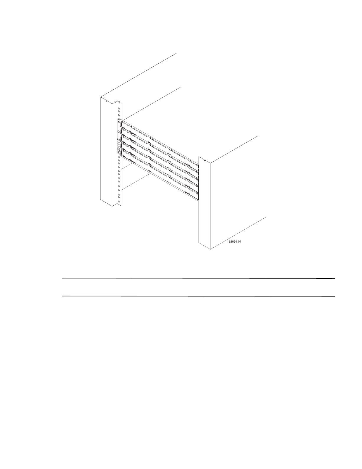
Figure 38 Controller-Drive Tray Installed in the Cabinet
15. Slide the fan canister all the way back into the drive tray until the tab on the fan canister latches.
16. Attach the bezel onto the front of the controller-drive tray.
NOTE If the E2660 controller-drive tray needs to have drives installed, refer to Steps to Install – Drives on the
DE6600 Drive Tray on page 77.
44 E2600 Controller-Drive Tray Installation Guide
Page 53
Step 5 - Connecting the E2600 Controller-Drive Tray to the Hosts
Key Terms
direct topology
A topology that does not use a switch.
switch topology
A topology that uses a switch.
topology
The logical layout of the components of a computer system or network and their interconnections. Topology deals
with questions of what components are directly connected to other components from the standpoint of being able to
communicate. It does not deal with questions of physical location of components or interconnecting cables. (The
Dictionary of Storage Networking Terminology)
Things to Know – Host Channels
ATTENTION Possible hardware damage – To prevent electrostatic discharge damage to the tray, use proper
antistatic protection when you handle tray components.
Each controller has from two to six host ports.
Two of the host ports are standard and support 6-Gb/s SAS data rates.
Two to four of the host ports are optional, and, if present, are located on a host interface card (HIC). The
following types of HICs are supported:
NOTE In configurations where a HIC does not exist, the space is covered with a blank faceplate.
— Two SAS connectors at 6-Gb/s
— Four iSCSI connectors at 1-Gb/s
— Two iSCSI connectors at 10-Gb/s
— Four FC connectors at 8-Gb/s
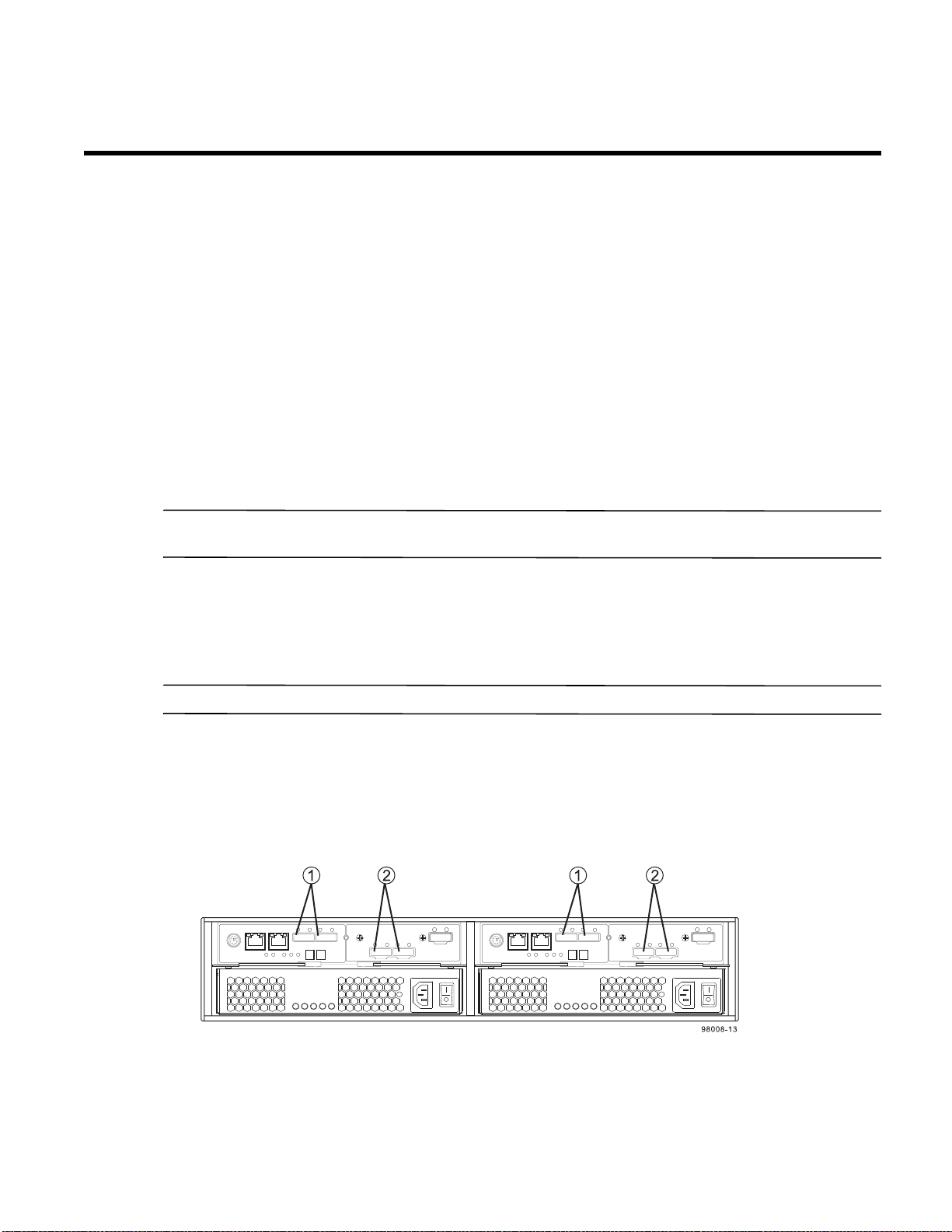
Figure 39 Host Channels on the E2612 and E2624 Controllers – Rear
View
1. Standard Host Connectors
2. Host Interface Card (HIC) Connectors (SAS in this Example)
E2600 Controller-Drive Tray Installation Guide 45
Page 54
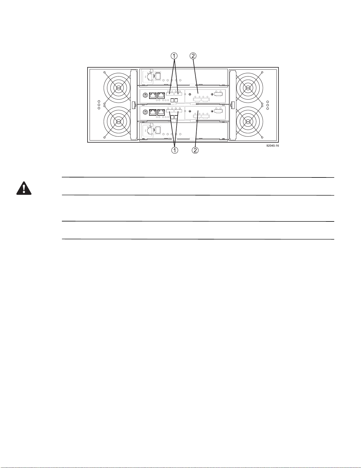
Figure 40 Host Channels on the E2660 Controllers – Rear View
1. Standard Host Connectors
2. Host Interface Card (HIC) Connectors (SAS in this Example)
WARNING (W03) Risk of exposure to laser radiation – Do not disassemble or remove any part of a Small
Form-factor Pluggable (SFP) transceiver because you might be exposed to laser radiation.
Procedure – Connecting Host Cables on a E2600 Controller-Drive Tray
NOTE Make sure that you have installed the HBAs. Refer to the documentation for the HBAs for information
about how to install the HBA and how to use the supplied configuration utilities.
The type of HICs (SAS, FC, or iSCSI) must match the type of the host bus adapters (HBAs) or network interface
cards (for iSCSI only) to which you connect them.
See the examples in the following section for example cabling patterns.
1. Perform one of these actions:
— You are using an FC HIC – Go to step 2.
— You are using either a SAS or an iSCSI HIC – Go to step 4. Connections for iSCSI use copper cables
with RJ-45 connectors and do not require SFP transceivers. Connection
s for SAS use SFF-8088
connectors.
2. Make sure that the appropriate type of SFP transceiver is inserted into the host
channel.
3. If a black, plastic plug is in the SFP transceiver, remove it.
4. Perform one of these actions:
— You are using either a SAS or an iSCSI HIC – Starting with the first host channel of each controller,
plug one end of the cable into the host channel.
— You are using an FC HIC – Starting with the first host channel of each controller, plug one end of the
cable into the SFP transceiver in the host channel.
The cable is either an Ethernet cable with
RJ-45 connectors for 1-Gb/s iSCSI connections, an SFF-8088
connector for 6-Gb/s SAS connections, or a fiber-optic cable for FC connections.
46 E2600 Controller-Drive Tray Installation Guide
Page 55
NOTE If Synchronous Mirroring connections are required, do not connect a host to the highest numbered host
channel because this channel is used for the mirrored communications.
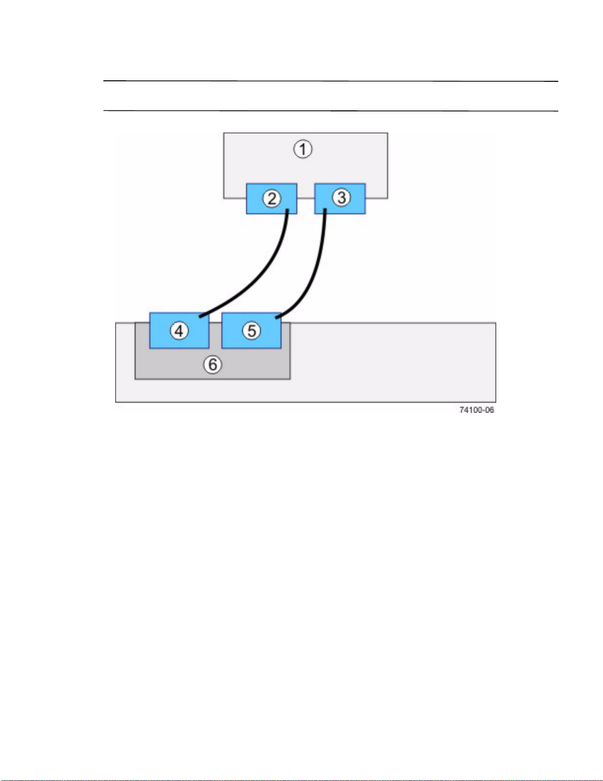
Figure 41 Direct Topology – One Host Connected to a Single Controller
1. Host
2. HBA 1 or NIC 1
3. HBA 2 or NIC 2
4. Host Port 1
5. Host Port 2
6. Controller A
E2600 Controller-Drive Tray Installation Guide 47
Page 56
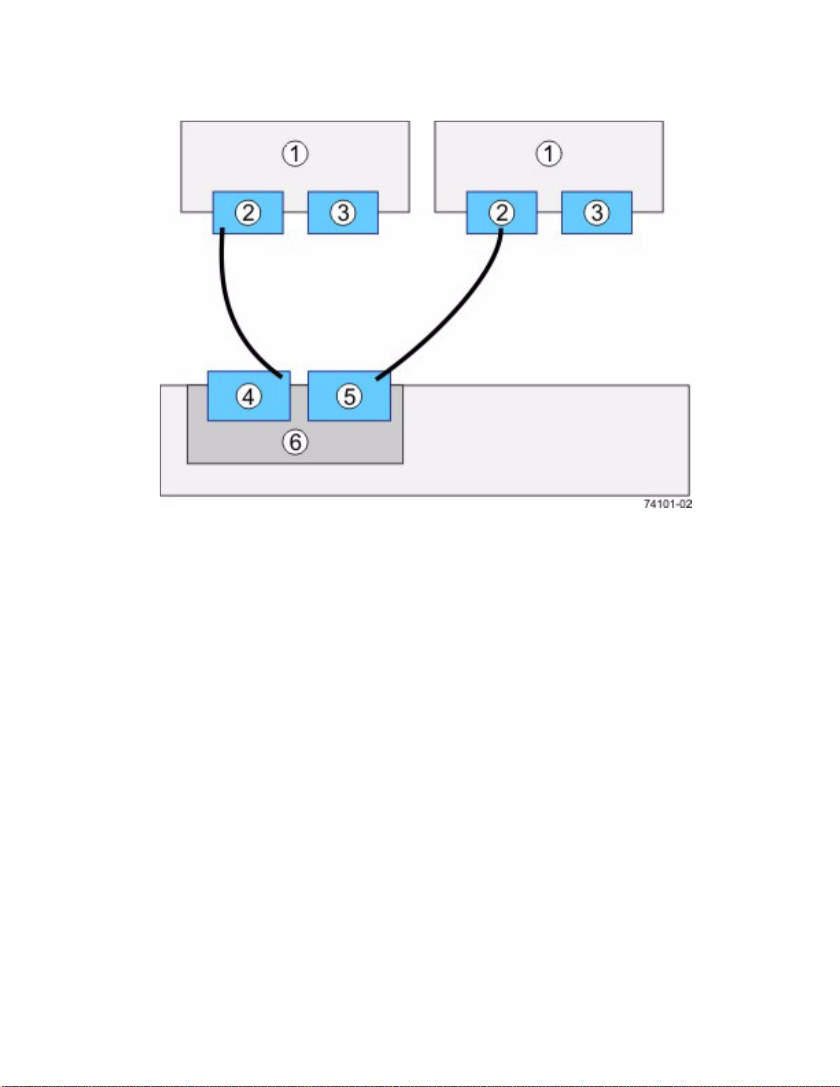
Figure 42 Direct Topology – Two Hosts Connected to a Single Controller
1. Host
2. HBA 1 or NIC 1
3. HBA 2 or NIC 2
4. Host Port 1
5. Host Port 2
6. Controller A
48 E2600 Controller-Drive Tray Installation Guide
Page 57
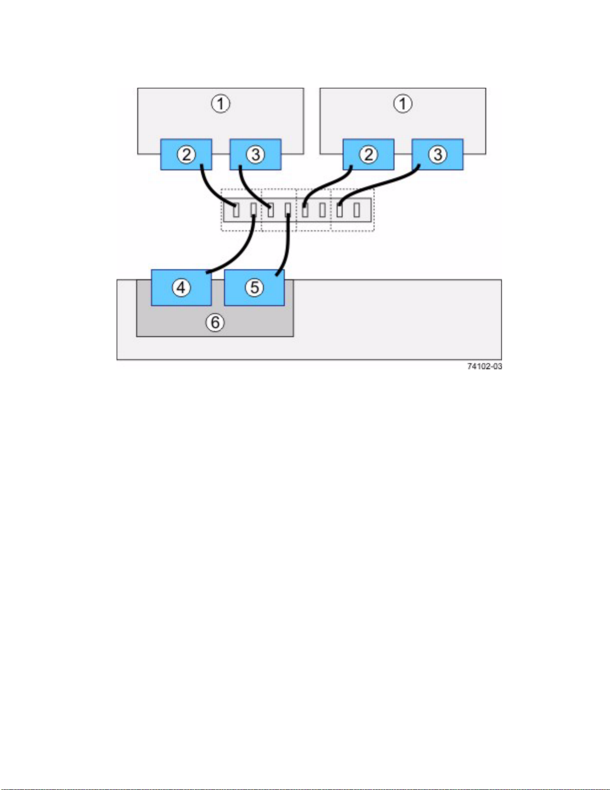
Figure 43 Switch Topology – Two Hosts Connected to a Single Controller Through a Switch
1. Host
2. HBA 1 or NIC 1
3. HBA 2 or NIC 2
4. Host Port 1
5. Host Port 2
6. Controller A
E2600 Controller-Drive Tray Installation Guide 49
Page 58
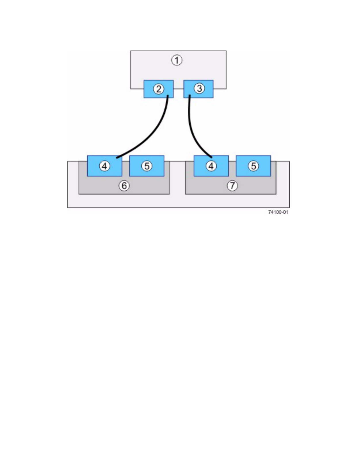
Figure 44 Direct Topology – One Host and a Dual Controller-Drive Tray
1. Host
2. HBA 1 or NIC 1
3. HBA 2 or NIC 2
4. Host Port 1
5. Host Port 2
6. Controller A
7. Controller B
50 E2600 Controller-Drive Tray Installation Guide
Page 59
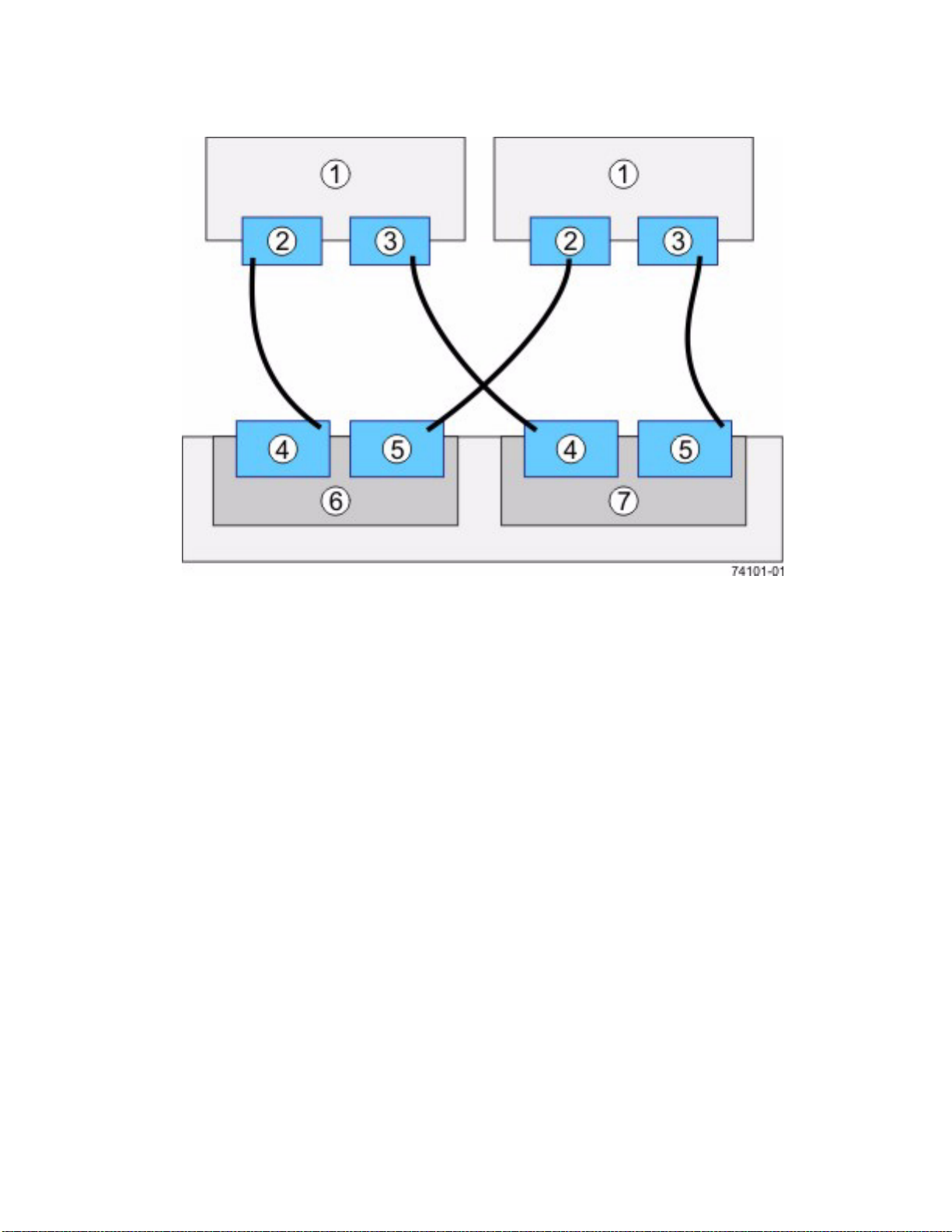
Figure 45 Direct Topology – Two Hosts and a Dual Controller-Drive Tray for Maximum Redundancy
1. Hosts
2. HBA 1 or NIC 1
3. HBA 2 or NIC 2
4. Host Port 1
5. Host Port 2
6. Controller A
7. Controller B
E2600 Controller-Drive Tray Installation Guide 51
Page 60
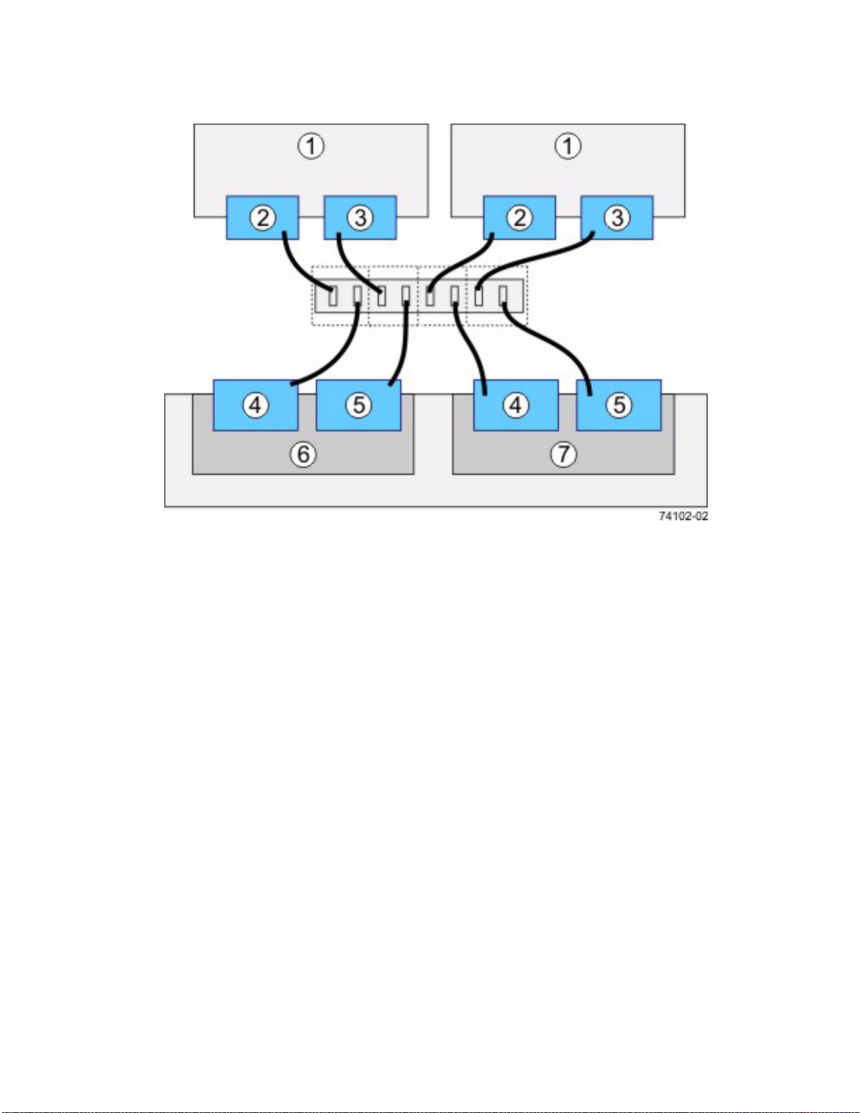
Figure 46 Mixed Topology – Two Hosts and a Dual Controller-Drive Tray
1. Hosts
2. HBA 1 or NIC 1
3. HBA 2 or NIC 2
4. Host Port 1
5. Host Port 2
6. Controller A
7. Controller B
52 E2600 Controller-Drive Tray Installation Guide
Page 61
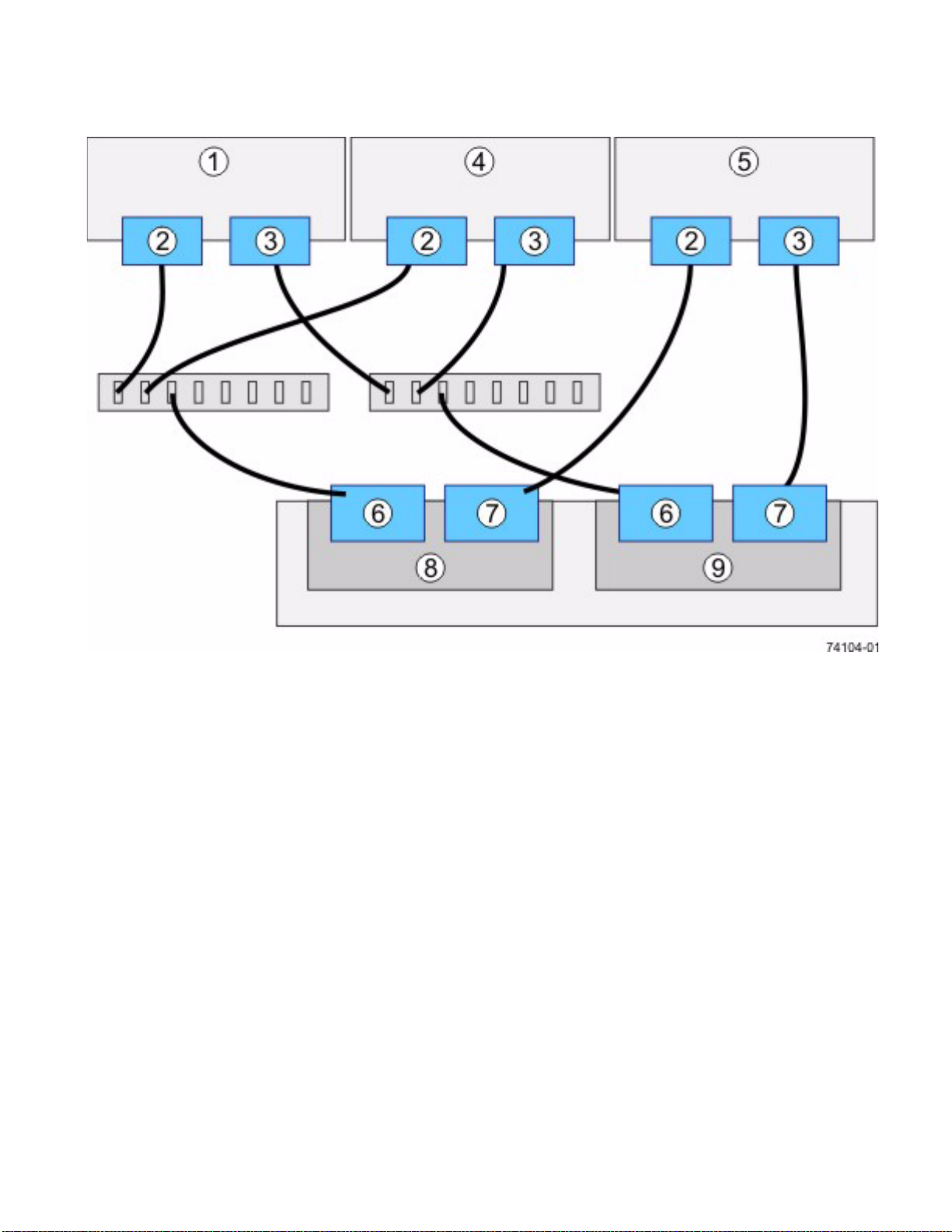
Figure 47 Mixed Topology – Three Hosts and a Dual Controller-Drive Tray
1. Host 1
2. HBA 1 or NIC 1
3. HBA 2 or NIC 2
4. Host 2
5. Host 3
6. Host Port 1
7. Host Port 2
8. Controller A
9. Controller B
5. Plug the other end of the cable either into an HBA in the host (direct topology) or into a switch (fabric
topology).
6. Affix a label to each end of the cable with this information. A label is very important if you need to disconnect
cables to service a controller. Include this information on the labels:
— The host name and the HBA port (for direct topology)
— The switch name and the port (for fabric topology)
— The controller ID (for example, controller A)
— The host channel ID (for example, host channel 1)
E2600 Controller-Drive Tray Installation Guide 53
Page 62

Example label abbreviation – Assume that a cable is connected between port 1 in HBA 1 of a host named
Engineering and host channel 1 of controller A. A label abbrev
iation could be as follows.
7. Repeat step 2 on page 46 through step 6 on page 53 for each controller and host channel that you intend to use.
54 E2600 Controller-Drive Tray Installation Guide
Page 63
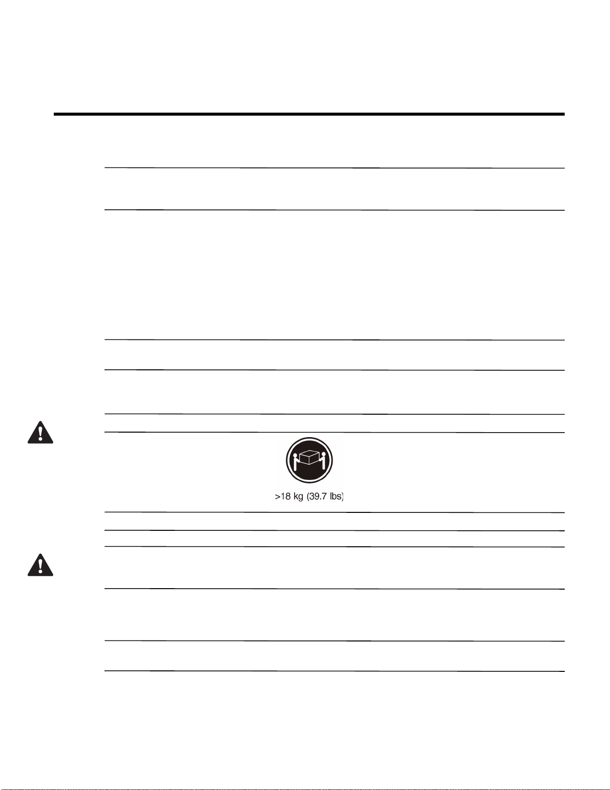
Step 6 - Installing the Drive Trays for the E2600 Controller-Drive Tray
Configurations
Things to Know – General Installation of Drive Trays with the E2600
Controller-Drive Tray
NOTE If you are installing the drive tray in a cabinet with other trays, make sure that the combined power
requirements of the drive tray and the other trays do not exceed the power capacity of your cabinet. For more
information, refer to the SANtricity ES Storage Manager Installation DVD.
Special site preparation is not required for any of these drive trays beyond what is normally found in a
computer lab environment.
The power supplies meet standard voltage requirements for both domestic and worldwide operation.
Take these precautions:
— Install the drive trays in locations within the cabinet that let you evenly distribute the drive trays around
the controller-drive tray.
— Keep as much weight as possible in the bottom half of the cabinet.
NOTE Refer to the Storage System Site Preparation Guide on the SANtricity ES Storage Manager Installation
DVD for important considerations about cabinet installation.
Procedure – Installing the DE1600 Drive Trays and the DE5600 Drive Trays
WARNING (W08) Risk of bodily injury –
Two persons are required to safely lift the component.
WARNING (W05) Risk of bodily injury – If the bottom half of the cabinet is empty, do not install components in
the top half of the cabinet. If the top half of the cabinet is too heavy for the bottom half, the cabinet might fall and
cause bodily injury. Always install a component in the lowest available position in the cabinet.
You can install the drive tray into an industry standard cabinet.
This procedure describes how to install the mounting rails into an industry standard cabinet.
ATTENTION Possible hardware damage – To prevent electrostatic discharge damage to the tray, use proper
antistatic protection when handling tray components.
E2600 Controller-Drive Tray Installation Guide 55
Page 64
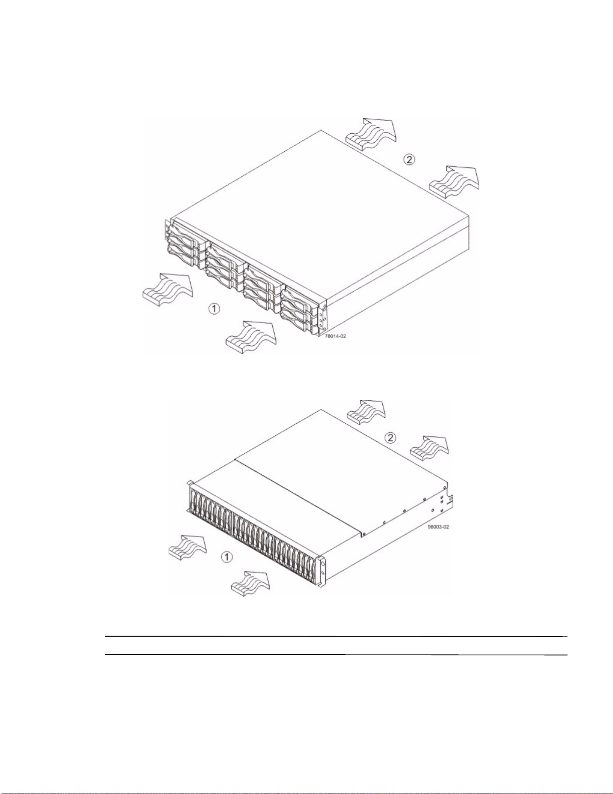
1. Make sure that the cabinet is in the final location. Make sure that you meet the clearance requirements shown
in the following two figures.
Figure 48 DE1600 Drive Tray Airflow and Clearance Requirements
1. 76 cm (30 in.) clearance in front of the cabinet
2. 61 cm (24 in.) clearance behind the cabinet
Figure 49 DE5600 Drive Tray Airflow and Clearance Requirements
1. 76 cm (30 in.) clearance in front of the cabinet
2. 61 cm (24 in.) clearance behind the cabinet
NOTE Fans pull air through the tray from front to back across the drives.
2. Lower the feet on the cabinet to keep the cabinet from moving.
3. Remove the drive tray and all contents from the shipping carton.
56 E2600 Controller-Drive Tray Installation Guide
Page 65
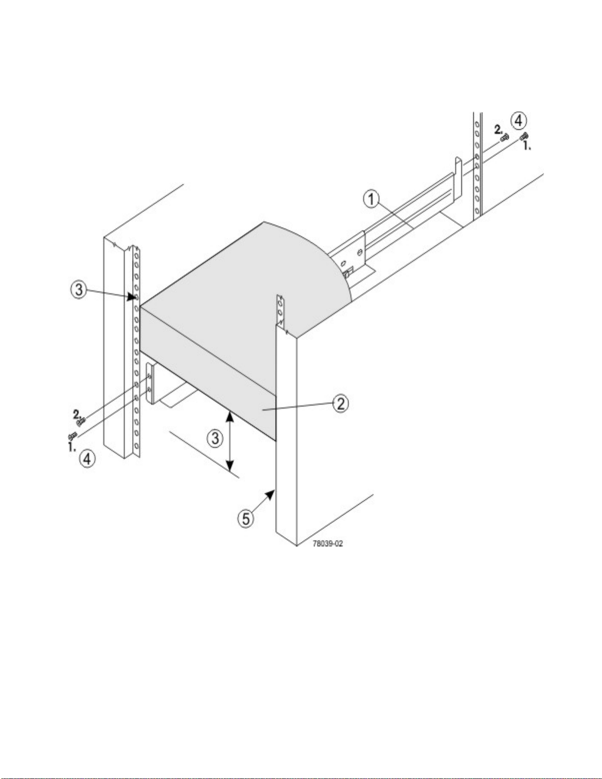
4. Position the mounting rails in the cabinet.
Figure 50 Positioning the Mounting Rails in the Cabinet
1. Mounting Rail
2. Existing Tray
3. Clearance Above and Below the Existing Tray
4. Screws for Securing the Mounting Rail to the Cabinet (Front and Rear)
5. Industry Standard Cabinet
— If you are installing the mounting rails above an existing tray, position the mounting rails directly above
the tray.
— If you are installing the mounting rails below an existing tray, allow 8.8-cm (3.5-in.) vertical clearance for
the drive tray.
E2600 Controller-Drive Tray Installation Guide 57
Page 66
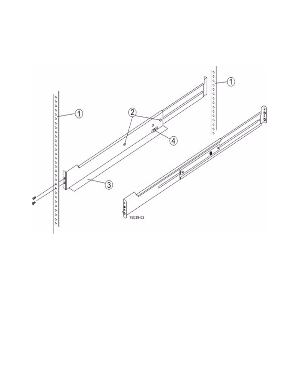
5. Attach the mounting rails to the cabinet by performing these substeps:
a. Make sure that the adjustment screws on the mounting rail are loose so that the mounting rail can
extend or contract as needed.
Figure 51 Attaching the Mounting Rails to the Cabinet
1. Cabinet Mounting Holes
2. Adjustment Screws for Locking the Mounting Rail Length
3. Mounting Rails
4. Clip for Securing the Rear of the Drive Tray
b. Place the mounting rail inside the cabinet, and extend the mounting rail until the flanges on the
mounting rail touch the inside of the cabinet.
58 E2600 Controller-Drive Tray Installation Guide
Page 67
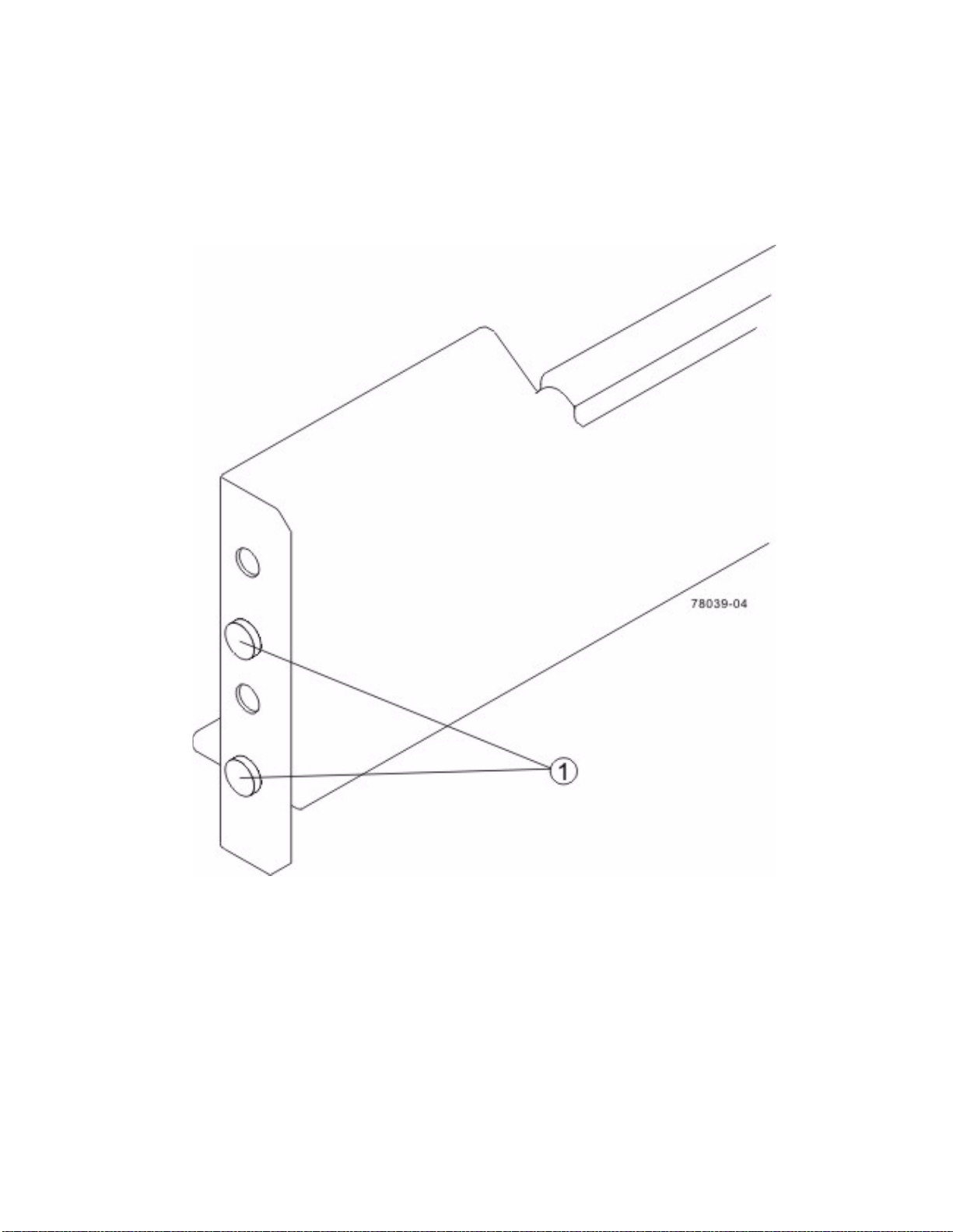
c. Make sure that the alignment spacers on the front flange of the mounting rail fit into the mounting
holes in the cabinet.
The front flange of each mounting rail has two alignment spacers. The alignm
fit into the mounting holes in the cabinet. The alignment spacers help position and hold the mounting rail.
Figure 52 Alignment Spacers on the Mounting Rail
ent spacers are designed to
1. Alignment Spacers
d. Insert one M5 screw through the front of the cabinet and into the top captured nut in the mounting
rail. Tighten the screw.
e. Insert two M5 screws through the rear of the cabinet and into the captured nuts in the rear flange in
the mounting rail. Tighten the screws.
f. Tighten the adjustment screws on the mounting rail.
g. Repeat substep a through substep f to install the second mounting rail.
E2600 Controller-Drive Tray Installation Guide 59
Page 68
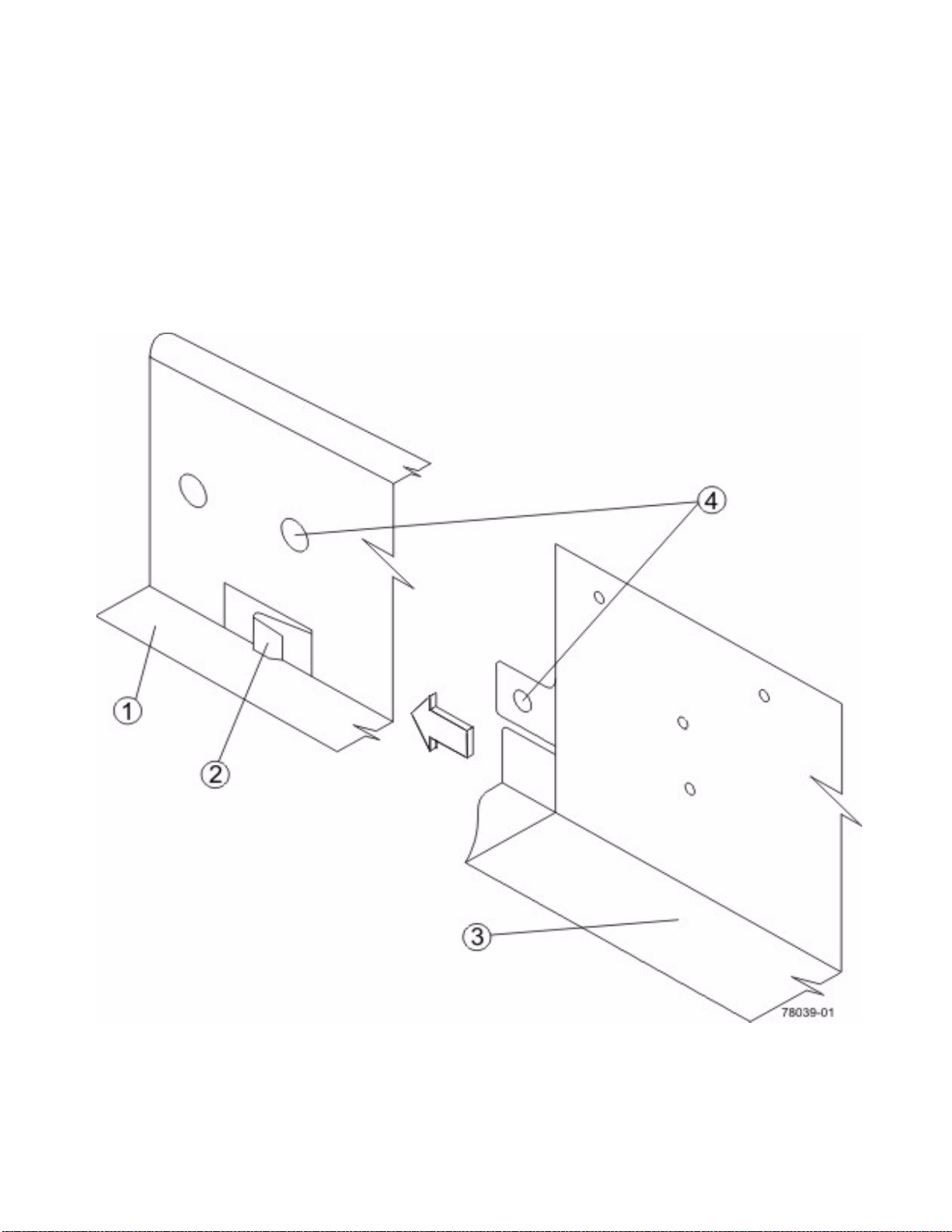
6. With the help of one other person, slide the rear of the drive tray onto the mounting rails. The rear edge of the
drive tray must fit into the clip on the mounting rail. The drive tray is correctly aligned when these conditions
are met:
— The mounting holes on the front flanges of the drive tray align with the mounting holes on the front of the
mounting rails. Refer to item 4 in the following figure.
— The rear edge of the drive tray sheet metal fits into the clip on the mounting rail.
— The holes in the drive tray sheet metal for the rear hold-down screws align with the captured nuts in the
side of the mounting rails.
Figure 53 Sliding the Drive Tray into the Clip on the Mounting Rail
1. Mounting Rail
2. Clip
3. Partial View of the Drive Tray Rear Sheet Metal
4. Mounting Holes
60 E2600 Controller-Drive Tray Installation Guide
Page 69
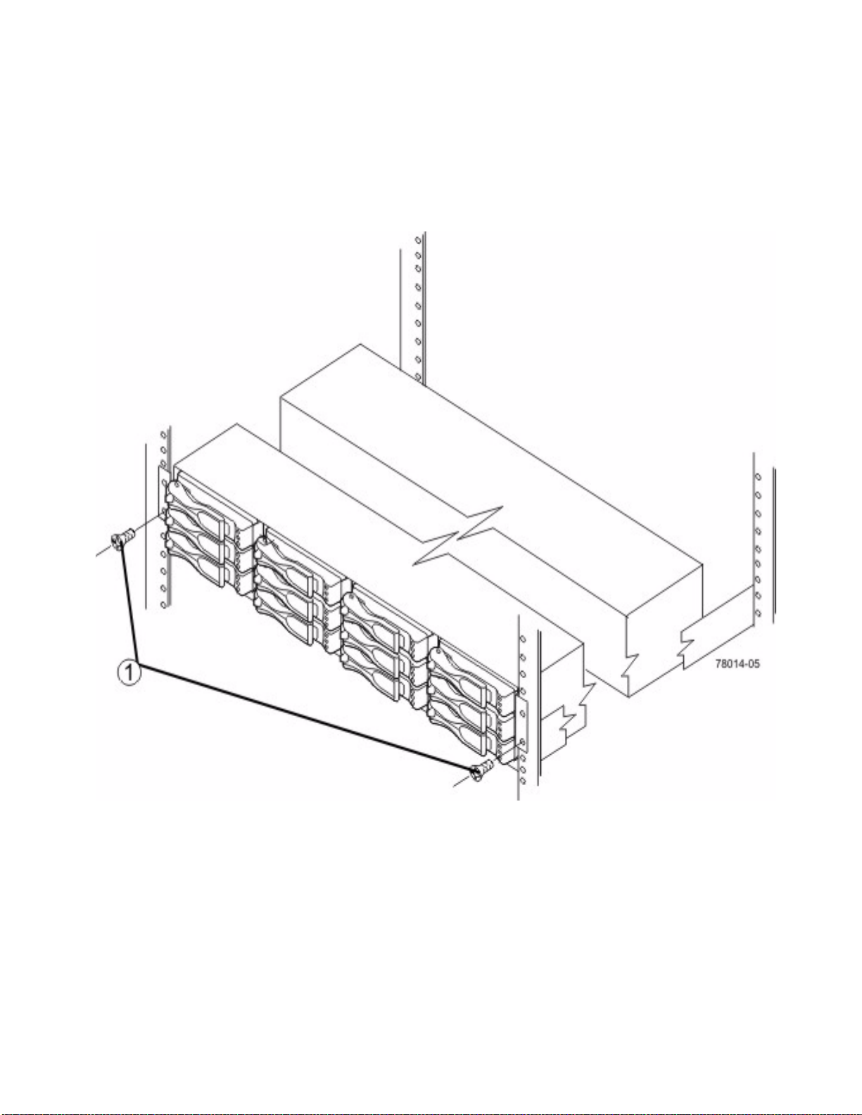
7. Secure the front of the drive tray to the cabinet. Use the two screws to attach the flange on each side of the front
of the drive tray to the mounting rails.
a. Insert one M5 screw through the bottom hole of a flange on the drive tray so that the screw goes
through the cabinet rail and engages the bottom captured nut in the mounting rail. Tighten the screw.
b. Repeat substep a for the second flange.
Figure 54 Attaching the Front of the DE1600 Drive Tray
1. Screws for Securing the Front of the Drive Tray
E2600 Controller-Drive Tray Installation Guide 61
Page 70
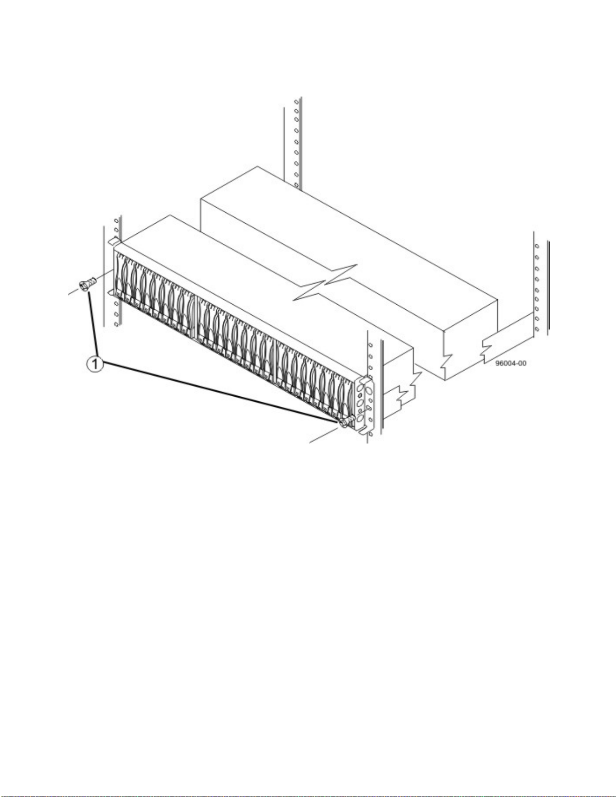
Figure 55 Attaching the Front of the DE5600 Drive Tray
1. Screws for Securing the Front of the Drive Tray
8. Secure the side of the drive tray to the mounting rails by performing these substeps:
a. Insert one M5 screw through the side sheet metal of the drive tray into the captured nut on the side of
the mounting rail. Tighten the screw.
b. Repeat substep a for the other side.
62 E2600 Controller-Drive Tray Installation Guide
Page 71
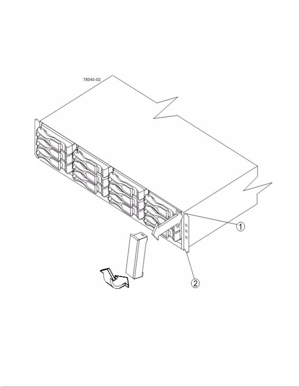
9. Attach the plastic end caps onto the front of the drive tray.
a. Put the top of the end cap on the hinge tab that is part of the drive tray mounting flange.
b. Gently press on the bottom of the end cap until it snaps into place over the retainer on the bottom of
the drive tray mounting flange.
Figure 56 Attaching the End Caps to the DE1600 Drive Tray
1. Hinge Tab
2. Retainer
E2600 Controller-Drive Tray Installation Guide 63
Page 72
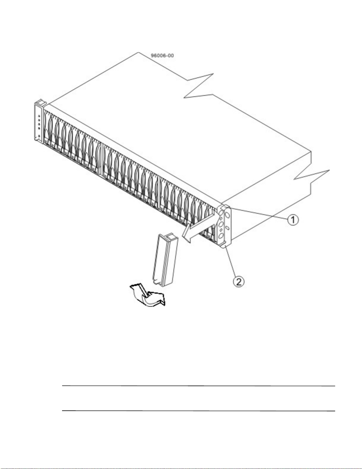
Figure 57 Attaching the End Caps to the DE5600 Drive Tray
1. Hinge Tab
2. Retainer
Procedure – Installing Drives in the DE1600 Drive Trays and the DE5600 Drive
Tray s
In some situations, the drive tray might be delivered without the drives installed. Follow the steps in this procedure
to install the drives. If your drive tray already has drives installed, you can skip this step and go to either "Things to
Know – AC Power Cords" on page 93 or "Things to Know – DC Power Cords" on page 93.
ATTENTION Risk of equipment malfunction – To avoid exceeding the functional and environmental limits,
install only drives that have been provided or approved by the original manufacturer. Drives might be shipped but
not installed. System integrators, resellers, system administrators, or users can install the drives.
64 E2600 Controller-Drive Tray Installation Guide
Page 73
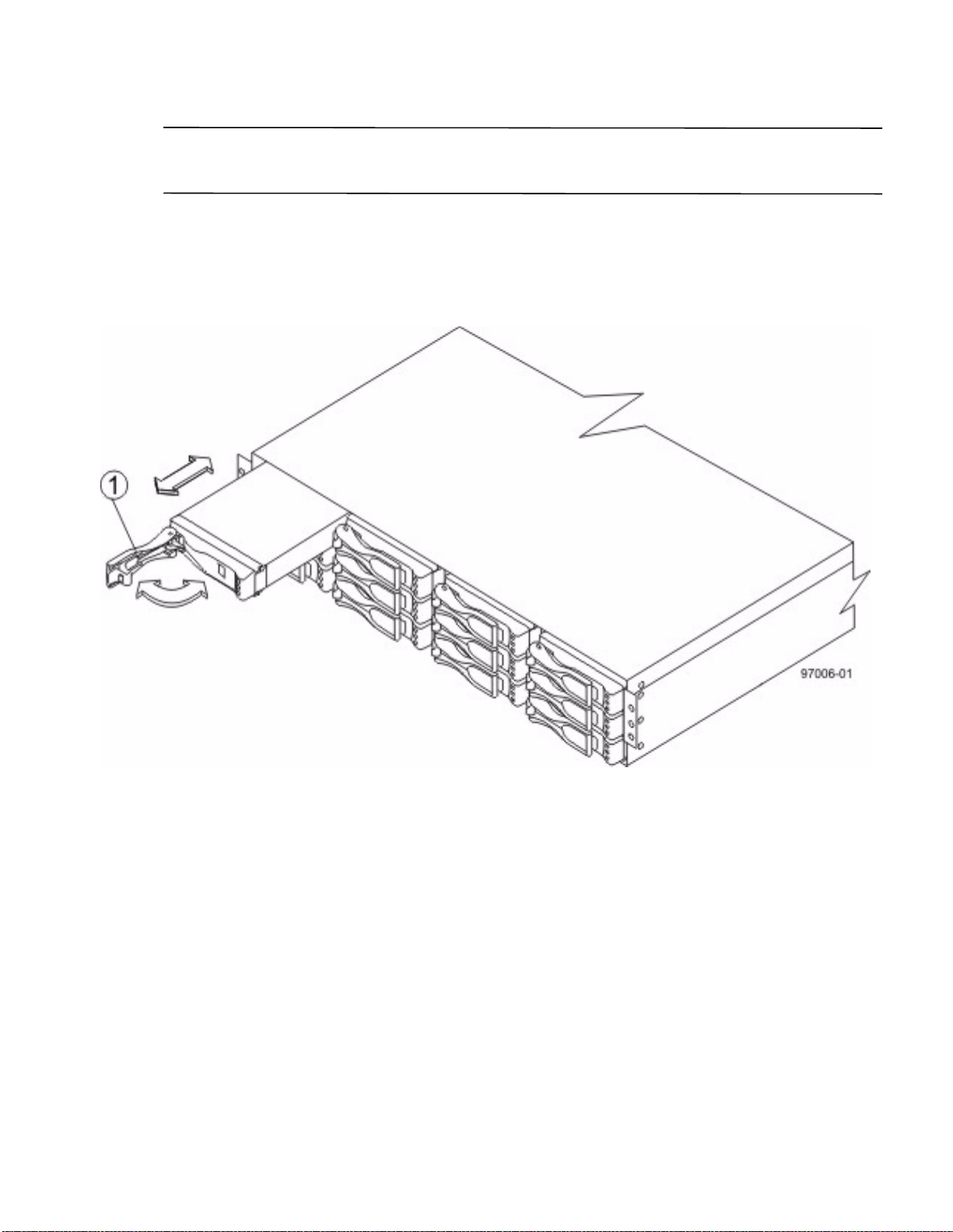
NOTE The installation order is from top to bottom and from left to right. The installation order is important
because the drives might already contain configuration information that depends upon the correct sequence of the
drives in the tray.
1. Beginning with the first drive slot in the upper-left side of the drive tray, place the drive on the slot guides, and
slide the drive all the way into the slot.
2. Push the drive handle to the right (DE1600 drive tray) or down (DE5600 drive tray) to lock the drive securely
in place.
Figure 58 Installing a Drive in the DE1600 Drive Tray
1. Drive Handle
E2600 Controller-Drive Tray Installation Guide 65
Page 74
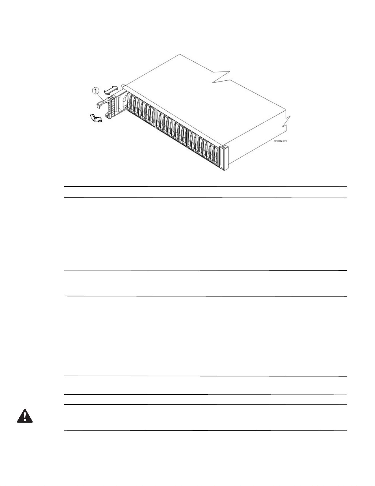
Figure 59 Installing a Drive in the DE5600 Drive Tray
1. Drive Handle
NOTE In some applications, the drive handle might have the hinge on the right.
3. Install the second drive beneath the first drive (DE1600 drive tray) or to the right of the first drive (DE5600
drive tray).
4. Install the other drives from top to bottom and then from left to right (DE1600 drive tray) or to the right
(DE5600 drive tray).
Things to Know – General Installation of Drive Trays with the E2660
Controller-Drive Tray
NOTE If you are installing the drive tray in a cabinet with other trays, make sure that the combined power
requirements of the drive tray and the other trays do not exceed the power capacity of your cabinet. For more
information, refer to the SANtricity ES Storage Manager Installation DVD.
Special site preparation is not required for any of these drive trays beyond what is normally found in a
computer lab environment.
The power supplies meet standard voltage requirements for both domestic and worldwide operation.
Take these precautions:
— Install the drive trays in locations within the cabinet that let you evenly distribute the drive trays around
the controller-drive tray.
— Keep as much weight as possible in the bottom half of the cabinet.
NOTE Refer to the Storage System Site Preparation Guide on the SANtricity ES Storage Manager Installation
DVD for important considerations about cabinet installation.
WARNING (W15) Risk of bodily injury – An empty tray weighs approximately 56.7 kg (125 lb). Three persons
are required to safely move an empty tray. If the tray is populated with components, a mechanized lift is required to
safely move the tray.
66 E2600 Controller-Drive Tray Installation Guide
Page 75
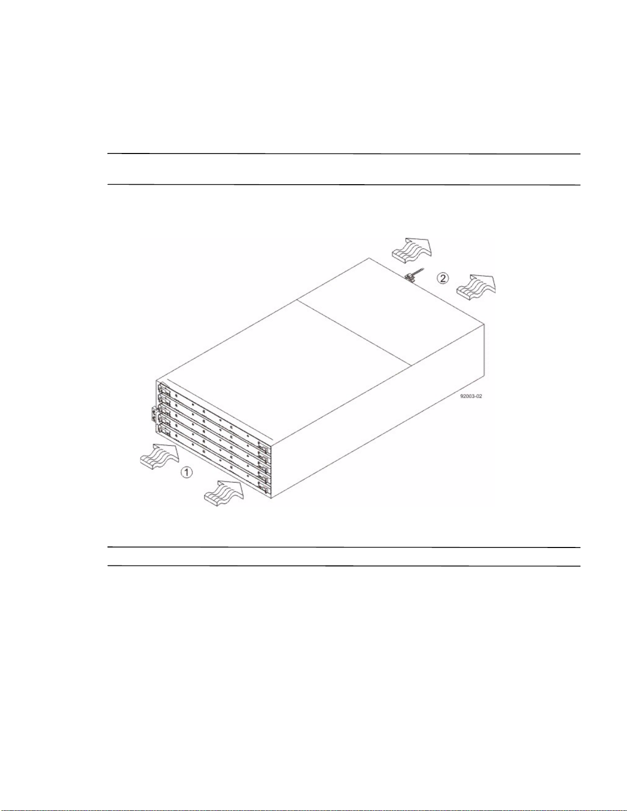
Steps to Install –DE6600 Drive Tray
You can install the high-density, 6-Gb SAS SBB 2.0-compliant DE6600 drive tray into an Industry-standard
cabinet, provided it has a depth of 100 cm (40 in.).
A minimum depth of 76 cm (30 in.) between the front EIA support rails and the rear EIA support rails is required.
NOTE If you are mounting the DE6600 drive tray in a cabinet with square holes, use the eight shoulder washers
in the rail kit to align the screws in the holes (see step 4 on page 69 through step 7 on page 71).
1. Make sure that the cabinet is in the final location. Make sure that you meet the clearan
in the following figure.
Figure 60 Drive Tray Airflow and Clearance Requirements
ce requirements shown
1. 81 cm (32 in.) clearance in front of the cabinet
2. 61 cm (24 in.) clearance behind the cabinet
NOTE Fans pull air through the drive tray from front to back across the drives.
E2600 Controller-Drive Tray Installation Guide 67
Page 76
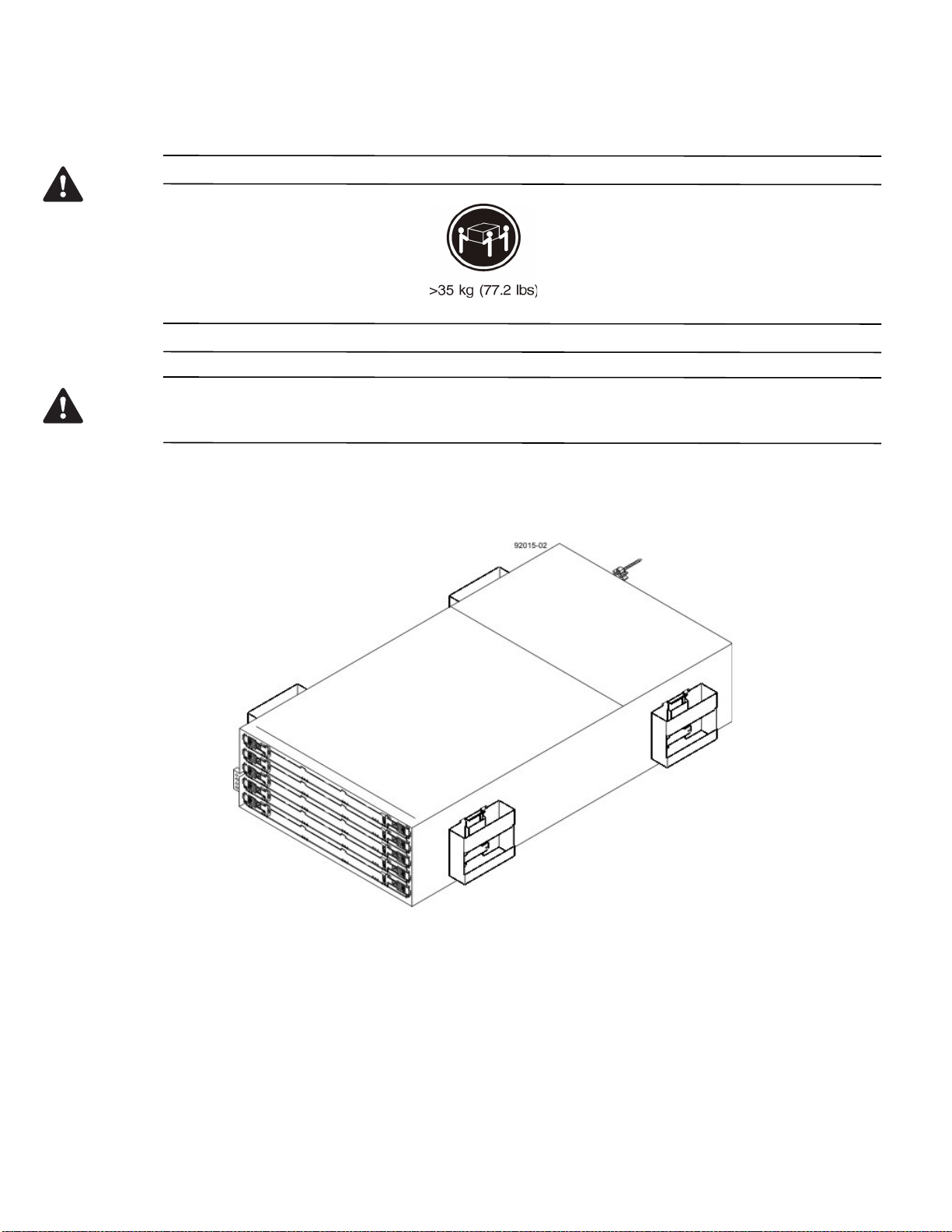
2. Lower the feet on the cabinet to keep the cabinet from moving.
WARNING (W09) Risk of bodily injury –
Three persons are required to safely lift the component.
WARNING (W15) Risk of bodily injury – An empty tray weighs approximately 56.7 kg (125 lb). Three persons
are required to safely move an empty tray. If the tray is populated with components, a mechanized lift is required to
safely move the tray.
3. With the help of at least two other persons, remove the drive tray and all of the contents from the shipping
carton, using the four drive tray handles (two to a side) as shown in the following figure. Set the drive tray
aside.
Figure 61 DE6600 Drive Tray with Drive Tray Handles (Two on Each Side)
68 E2600 Controller-Drive Tray Installation Guide
Page 77
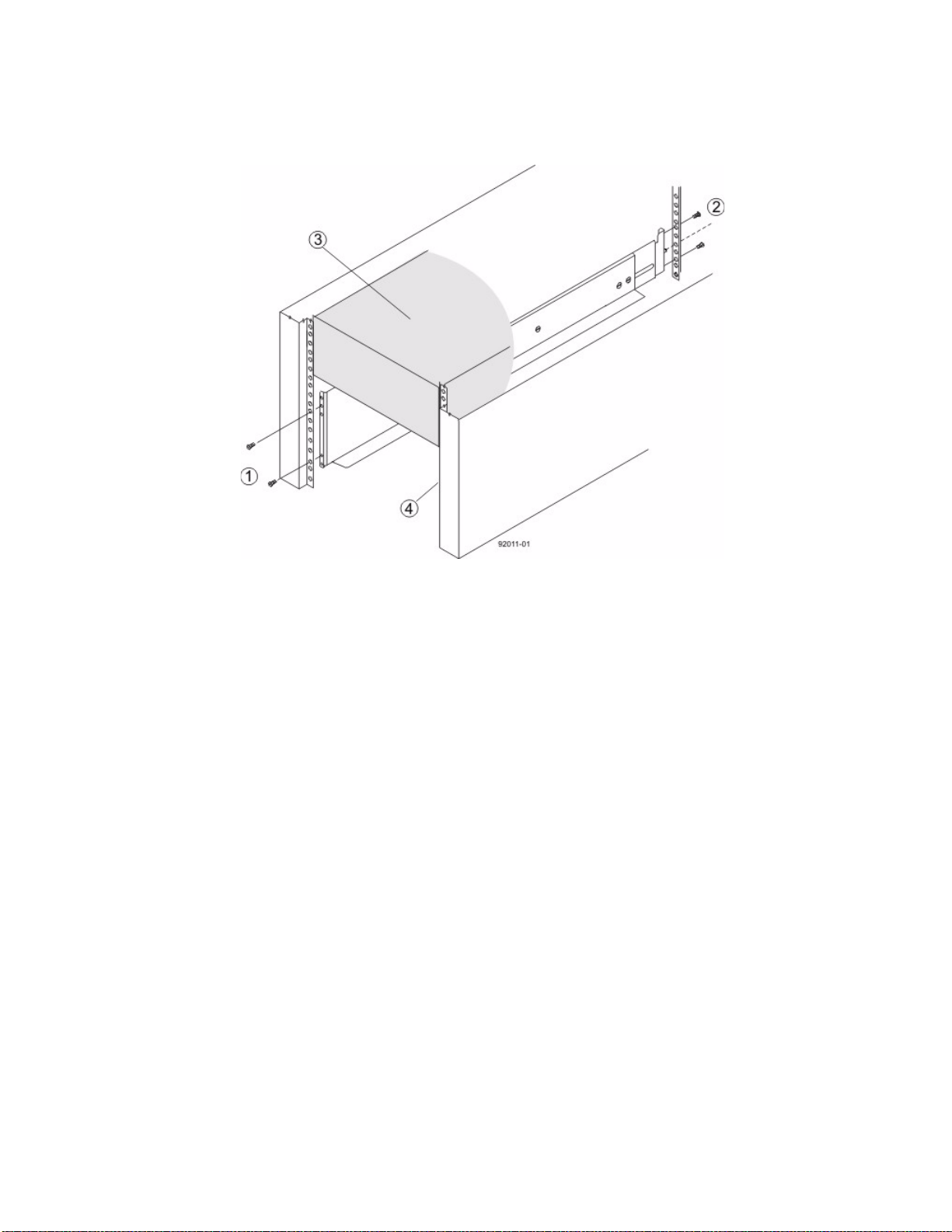
4. Position the mounting rails in the cabinet.
Figure 62 Positioning the Mounting Rails in the Cabinet
1. Screws for Securing the Mounting Rail to the Cabinet (Front)
2. Screws for Securing the Mounting Rail to the Cabinet (Rear)
3. Existing Tray
4. Industry Standard Cabinet
— If you are installing the mounting rails above an existing tray, position the mounting rails directly above
the tray.
— If you are installing the mounting rails below an existing tray, allow 17.8-cm (7-in.) vertical clearance for
a DE6600 drive tray.
5. To attach the mounting rails to the cabinet, do one of
— If you are using the long fixed size mounting rails, go to step 6.
— If you are using the shorter adjustable mounting rails, go to step 7.
the following:
6. To attach the long mounting rails to the cabinet, perform these substeps:
a. M
ake sure that the adjustment screws on the mounting rail are loose so that the mounting rail can
extend or contract as needed.
E2600 Controller-Drive Tray Installation Guide 69
Page 78
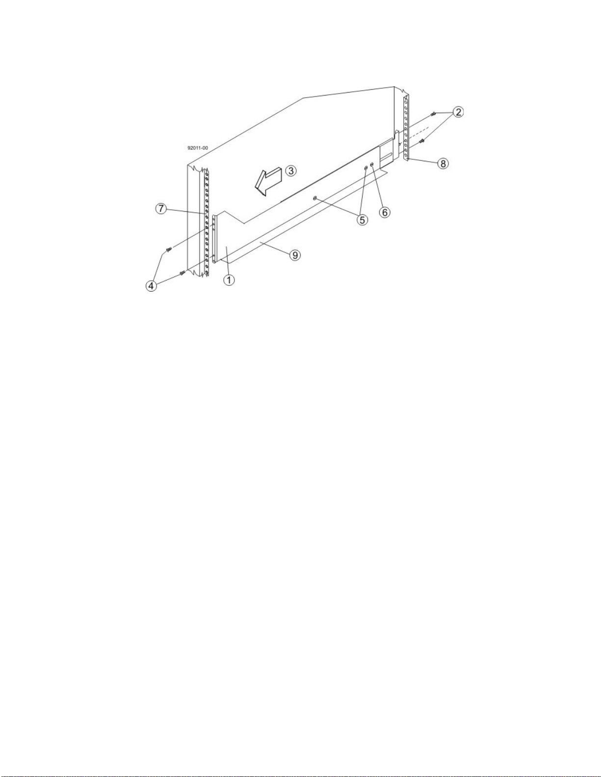
Figure 63 Attaching the Long Mounting Rails to the Cabinet
1. Front of the Mounting Rail
2. Two M5 Screws for the Rear EIA Support Rail
3. Front of the Cabinet
4. Two M5 Screws for the Front EIA Support Rail
5. Adjustable Rail Tightening Screws
6. Rear Hold-Down Screw
7. Cabinet Mounting Holes on the Front EIA Support Rail
8. Cabinet Mounting Holes on the Rear EIA Support Rail
9. Mounting Rail Lip
b. Remove the rear hold-down screw. It protrudes from the inside of the rail and prevents you from
sliding the drive tray onto the rails.
c. Place the mounting rail inside the cabinet, and extend the mounting rail until the flanges on the
mounting rail touch the inside of the cabinet.
d. Insert one M5 screw through the front of the cabinet, and screw it into the top captured nut in the
mounting rail.
e. Insert two M5 screws through the rear of the cabinet, and screw them into the captured nuts in the
rear flange in the mounting rail.
f. Tighten the adjustment screws on the mounting rail.
g. Repeat substep a through substep f to install the second mounting rail.
h. Insert one M5 screw through the front of the mounting rail. You use this screw to attach the drive tray
to the cabinet.
70 E2600 Controller-Drive Tray Installation Guide
Page 79
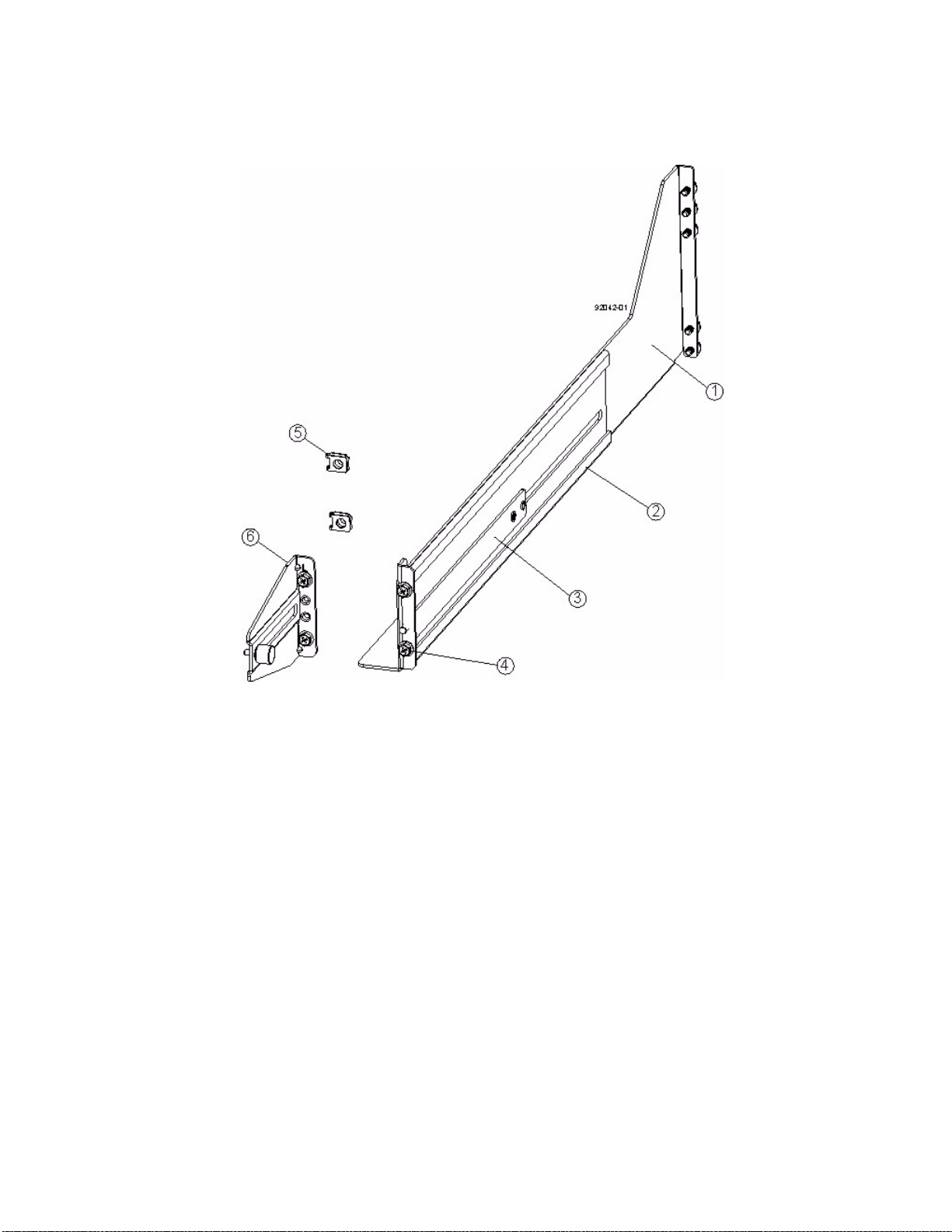
7. To attach the shorter, adjustable size mounting rails to the cabinet, perform these sets of substeps:
Figure 64 Short Adjustable Mounting Rail -- Left Side
1. Front of the Mounting Rail
2. Rear of the Mounting Rail
3. Rail Fix Bar
4. Two M5 Screws for the Front EIA Support Rail
5. Two Clips for the Front EIA Support Rail
6. Rear Bracket
a. Make sure that the adjustment screws on the mounting rail are loose so that the mounting rail can
extend or contract as needed (see the figure "Short Adjustable Mounting Rail -- Left Side").
b. Place the mounting rail inside the cabinet, and extend the mounting rail until the flanges on the
mounting rail touch the inside of the cabinet (see the figure "Short Adjustable Mounting Rail Attached
to the Cabinet" on page 72).
c. Insert one M5 screw through the front of the cabinet, and screw it into the top captured nut in the
mounting rail.
d. Insert two M5 screws through the rear of the cabinet, and screw them into the captured nuts in the
rear flange in the mounting rail.
e. Tighten the adjustment screws on the mounting rail.
f. Repeat substep a through substep e to install the second mounting rail.
E2600 Controller-Drive Tray Installation Guide 71
Page 80
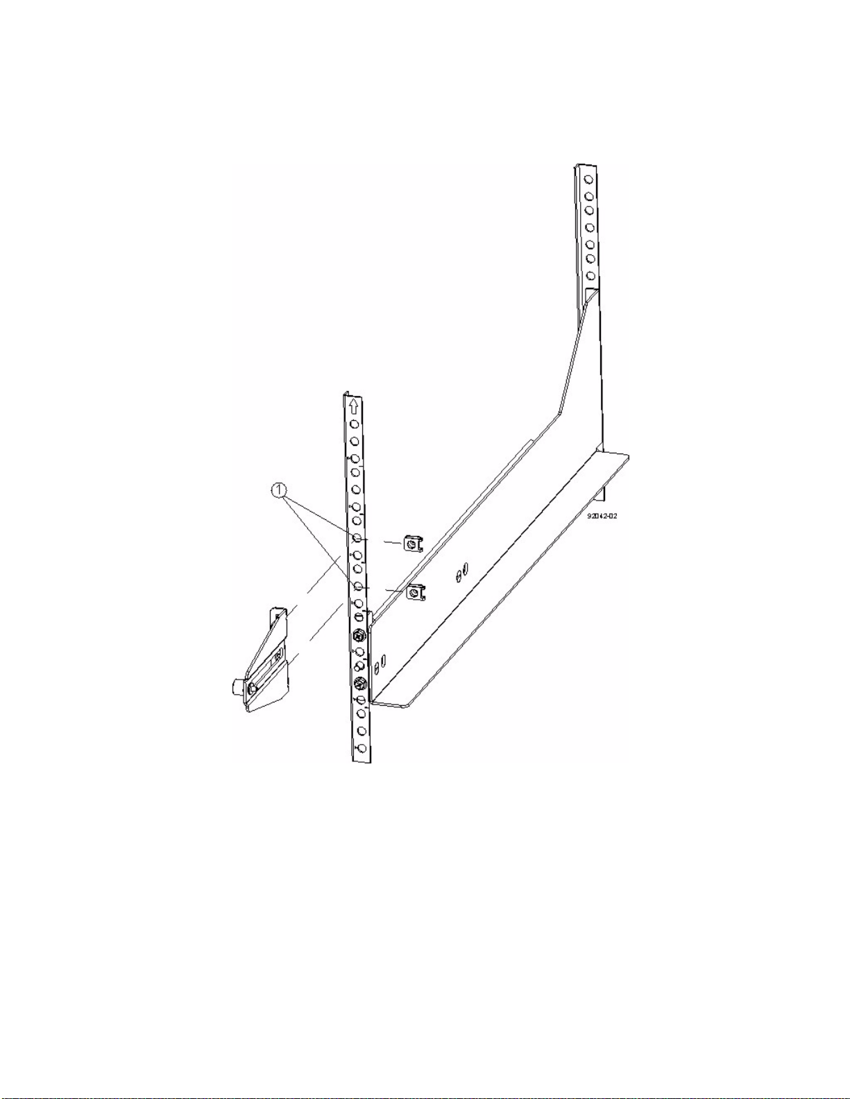
g. Insert one M5 screw through the front of the mounting rail. This screw attaches the drive tray to the
cabinet.
Figure 65 Short Adjustable Mounting Rail Attached to the Cabinet
1. Cabinet Mounting Holes on the Front EIA Support Rail
72 E2600 Controller-Drive Tray Installation Guide
Page 81
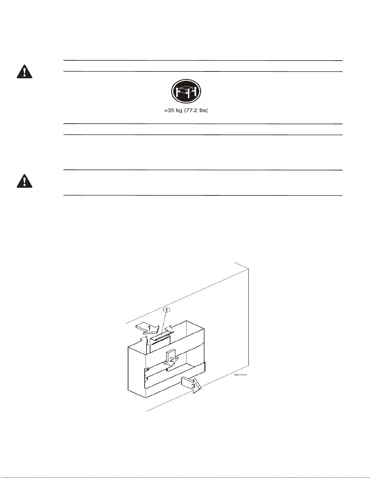
8. Remove the bezel from the front of the drive tray.
WARNING (W09) Risk of bodily injury –
Three persons are required to safely lift the component.
9. With the help of at least two other persons, slide the rear of the drive tray onto the mounting rails. The drive
tray is correctly aligned when the mounting holes on the front flanges of the drive tray align with the mounting
holes on the front of the mounting rails.
WARNING (W15) Risk of bodily injury – An empty tray weighs approximately 56.7 kg (125 lb). Three persons
are required to safely move an empty tray. If the tray is populated with components, a mechanized lift is required to
safely move the tray.
10. After the controller-drive tray is correctly aligned, remove the enclosure lift handles as shown in the figure
"Removing an Enclosure Lift Handle from the Drive Tray":
a. Use your thumb to unlatch and remove the rear enclosure lift handles (two to a side).
b. Use the front enclosure lift handles to slide the drive tray all the way into the cabinet.
c. After the drive tray is securely in the cabinet, use your thumb to unlatch and remove the front
enclosure lift handles (two to a side).
Figure 66 Removing an Enclosure Lift Handle from the Drive Tray
1. Pull the thumb latch away from the drive tray to detach the hook.
2. Shift the handle down to release the other four hooks.
3. Move the handle away from the drive tray.
E2600 Controller-Drive Tray Installation Guide 73
Page 82
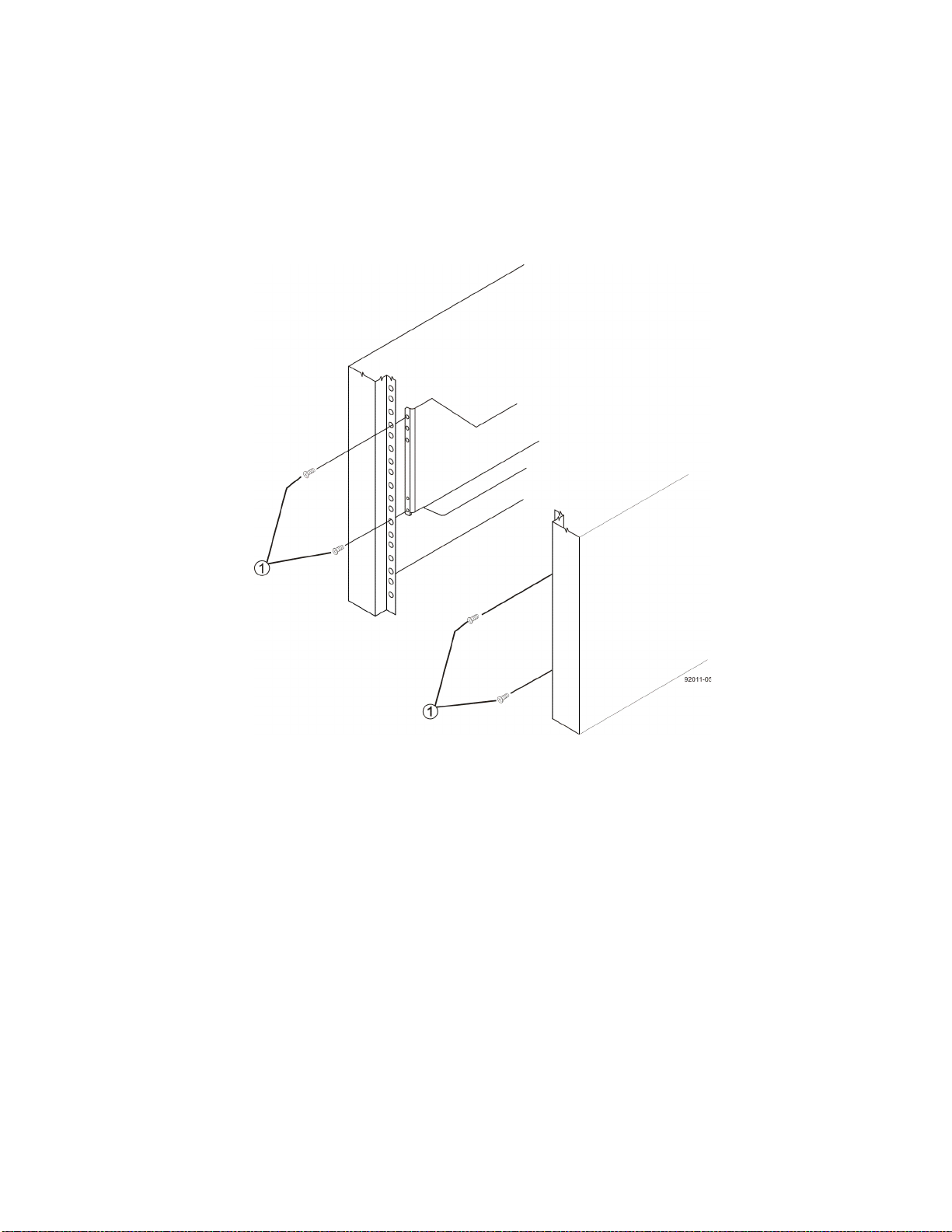
11. Secure the front of the drive tray to the cabinet. Use the four screws to attach the flange on each side of the
front of the drive tray to the mounting rails.
a. Insert two M5 screws through the bottom holes of a flange on the drive tray so that the screws go
through the EIA support rail and engage the bottom captured nuts in the mounting rail. Tighten the
screws.
b. Repeat substep a for the second flange.
Figure 67 Attaching the Front of the Drive Tray
1. Four Screws for Securing the Front of the Drive Tray
74 E2600 Controller-Drive Tray Installation Guide
Page 83
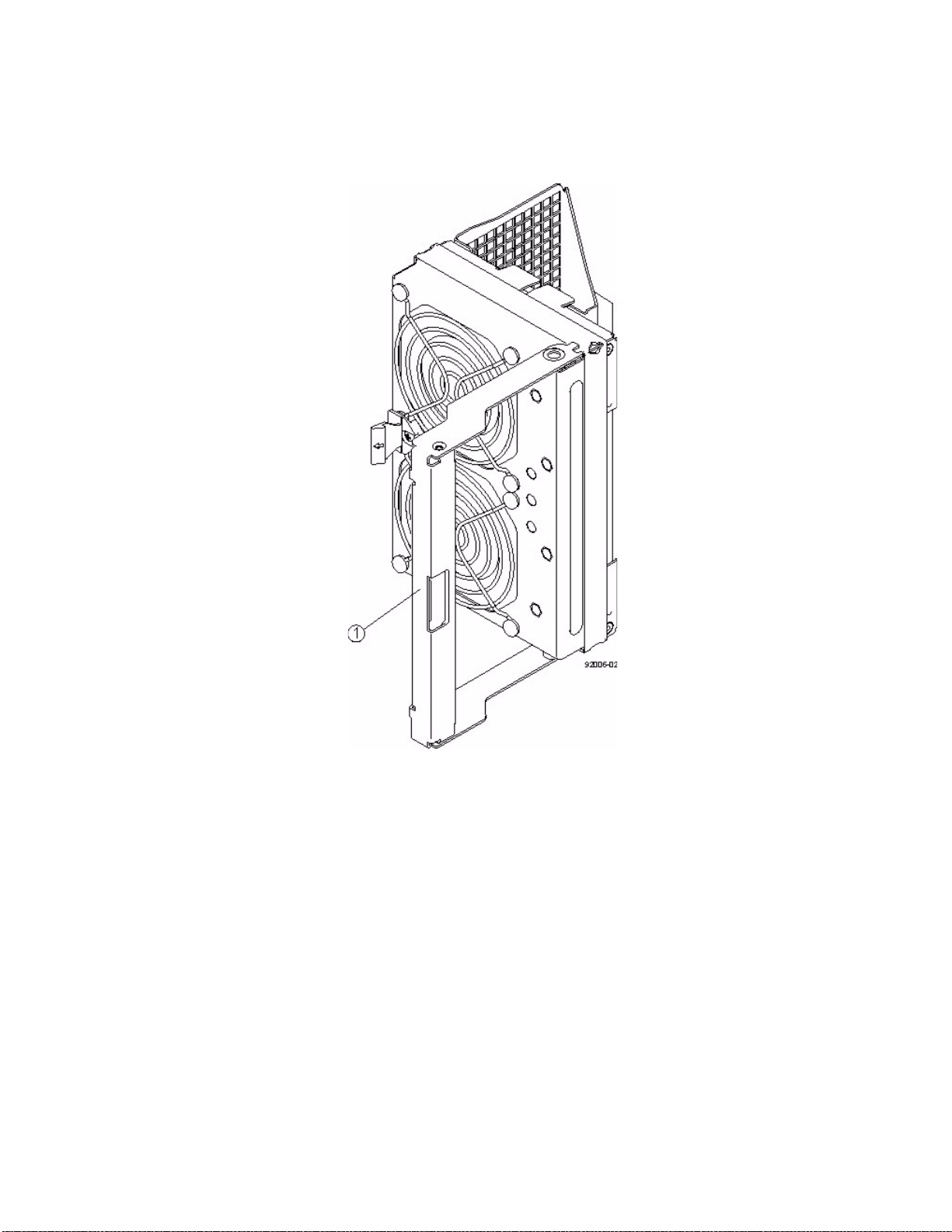
12. Remove the fan canister from the drive tray by pressing on the tab holding the fan canister handle in place, and
then pulling the fan canister toward you.
Figure 68 Removing the Fan Canister from the Drive Tray
1. Fan Canister Handle
13. Use the fan canister handle to pull the fan canister out of the drive tray.
E2600 Controller-Drive Tray Installation Guide 75
Page 84
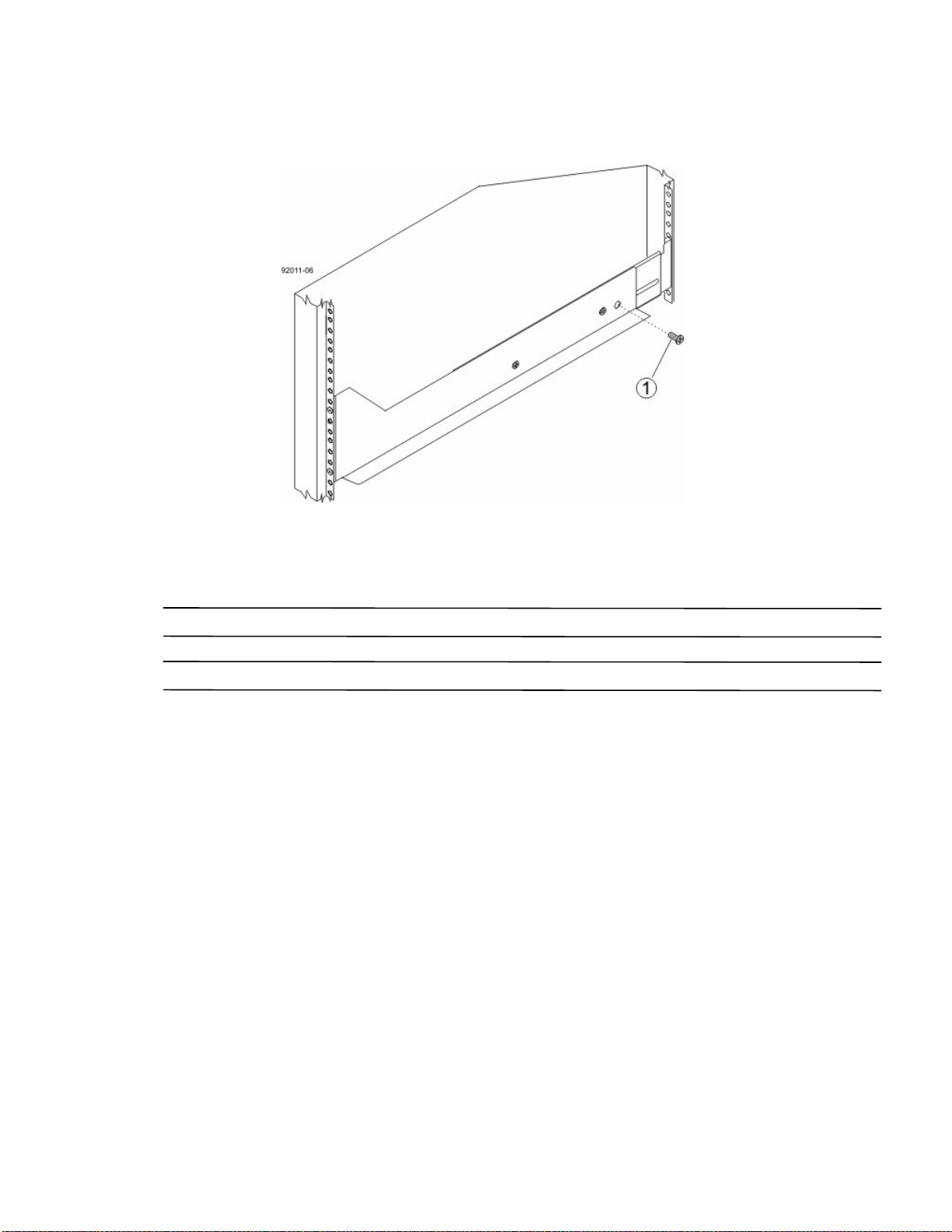
14. Secure the side of the drive tray to the mounting rails by performing these substeps:
Figure 69 Securing the Drive Tray to the Rails
1. 10-32 Screw
a. Insert a 10-32 screw through the side sheet metal of the drive tray into the captured nut on the side of
the mounting rail. Tighten the screws.
b. Repeat substep a for the other side.
NOTE After the drive tray is installed, there should be seven screws on each side (right and left) of the cabinet.
NOTE Make sure that each drive drawer in the drive tray is securely fastened to ensure proper air flow to the drives.
76 E2600 Controller-Drive Tray Installation Guide
Page 85
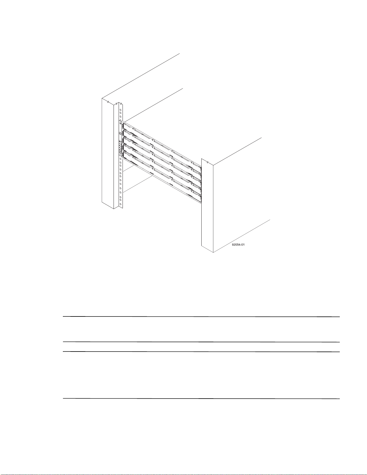
Figure 70 Drive Tray Installed in the Cabinet
15. Slide the fan canister all the way back into the drive tray until the tab on the fan canister latches.
16. Attach the bezel onto the front of the drive tray.
Steps to Install – Drives on the DE6600 Drive Tray
The DE6600 drive tray is shipped with the drive drawers installed, but the drives are not installed. Follow the steps
in this procedure to install the drives.
ATTENTION Risk of equipment malfunction – To avoid exceeding the functional and environmental limits,
install only drives that have been provided or approved by the original manufacturer. Drives might be shipped but
not installed. System integrators, resellers, system administrators, or users can install the drives.
NOTE The installation order within each drawer is from left to right in rows. Slots 1, 4, 7 and 10 must have a drive
installed in these locations to make sure there is sufficient air flow to the drives. To verify these slots, consult the
overlay on the front of each of the five drive drawers. Make sure that the four drives in each row are adjacent to each
other. The long edge of each drive should touch the drive next to it. To maintain a uniform airflow across all drive
drawers, the drive tray must be configured with a minimum of 20 drives, with four drives in the front row of each of
the five drive drawers.
E2600 Controller-Drive Tray Installation Guide 77
Page 86
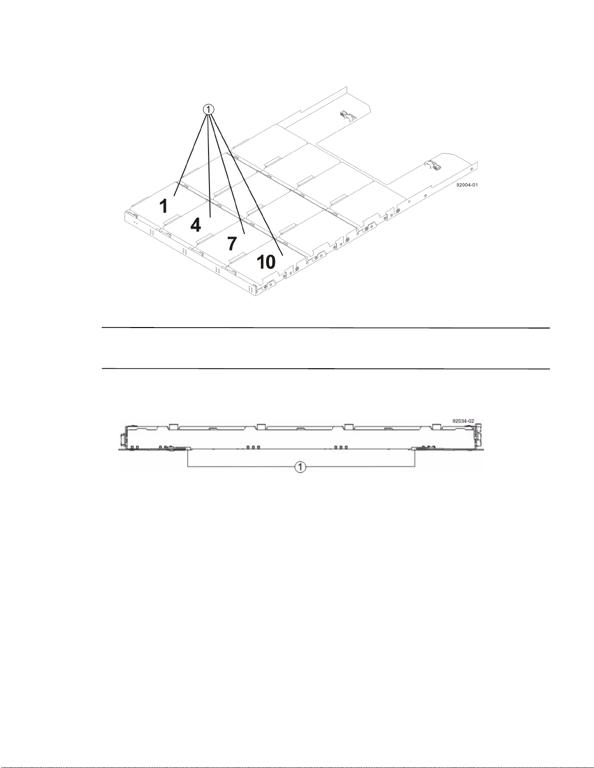
1. DE6600 Drive Tray with Slots 1, 4, 7, and 10
ATTENTION Risk of equipment malfunction – For the DE6600 drive tray, you can replace only one canister or
drive at a time. Refer to the “Replacing a Drive on the DE6600 Drive tray” instructions on the Software and
Documentation DVD, and make sure you have the replacement drive in hand before starting the task.
1. Beginning with the top drawer in the drive tray, release the levers on each side of the drawer by pulling both
towards the center.
Figure 71 Levers on the Drive Drawer
1. Levers to Release the Drive Drawer
2. Pull on the extended levers to pull the drive drawer out to its full extension without removing it from the drive
tray.
78 E2600 Controller-Drive Tray Installation Guide
Page 87
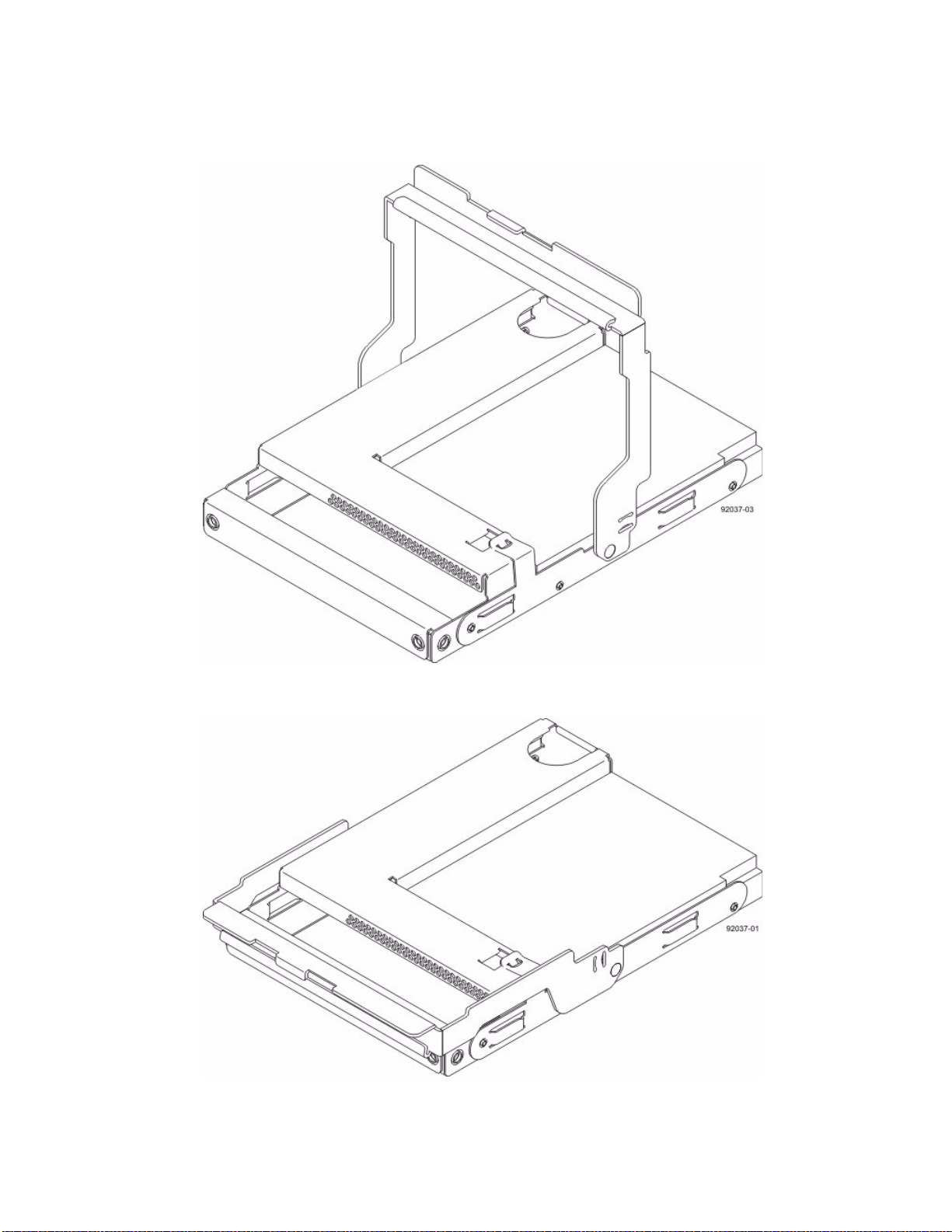
3. Starting with the first drive, raise the drive handle to the vertical position.
Figure 72 Raised Drive Handle
4. Align the two raised buttons on each side over the matching gap in the drive channel on the drawer.
Figure 73 Side View of Drive with Raised Handle
1. Raised Buttons
E2600 Controller-Drive Tray Installation Guide 79
Page 88
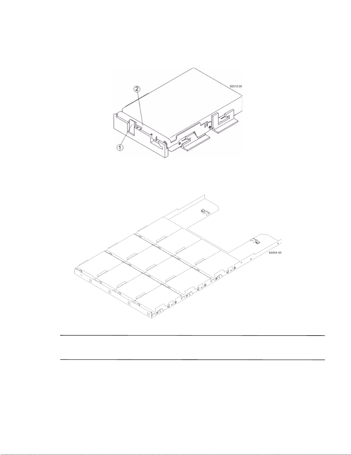
5. Lower the drive straight down, and then rotate the drive handle down until the drive snaps into place under the
drive release lever.
Figure 74 Drive Release Lever Locked by the Drive Handle
1. Drive Release Lever
2. Drive Handle
6. Install the other drives in rows from left to right until the drive drawer is fully populated.
Figure 75 Fully-Populated Drive Drawer
7. Push the drive drawer all the way back into the drive tray, closing the levers on each side of the drive drawer.
ATTENTION Risk of equipment malfunction – Make sure you push both levers to each side so that the drive
drawer is completely closed. The drive drawer must be completely closed to prevent excess airflow, which has the
potential to damage the drives.
8. Continue onto the next drive drawer, repeating step 1 through step 7 for each drive drawer in the configuration.
80 E2600 Controller-Drive Tray Installation Guide
Page 89
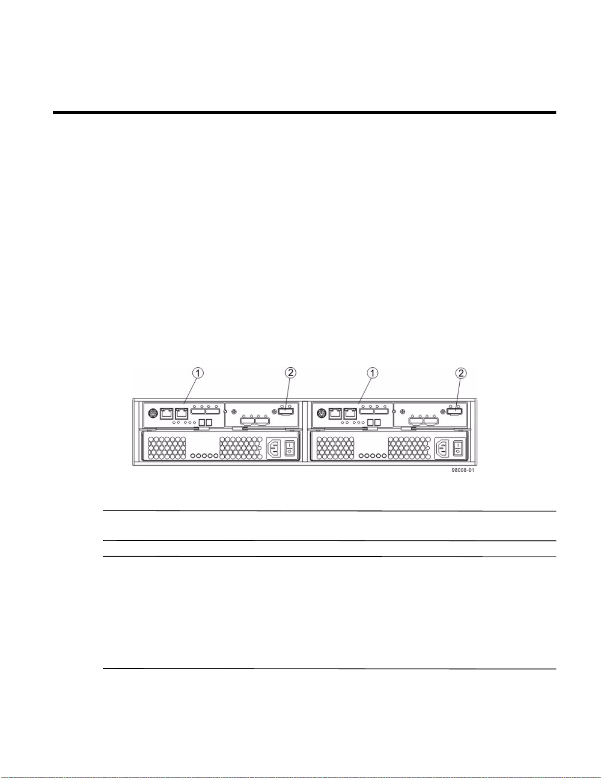
Step 7 - Connecting the E2600 Controller-Drive Tray to the Drive
Trays
Key Terms
drive channel
The path for the transfer of data between the controllers and the drives in the storage array.
Things to Know – E2600 Controller-Drive Tray
On the E2600 controller-drive tray, each controller has a pair of levers with handles for removing the controller
from the controller-drive tray. One of these handles on each controller is located next to a host connector. The close
spacing between the handle and the host connector might make it difficult to remove a cable that is attached to the
host connector. If this problem occurs, use a flat-blade screwdriver to push in the release component on the cable
connector.
The E2600 controller-drive tray supports both the DE1600 drive tray and the DE5600 drive tray for expansion.
The maximum number of drive slots in the storage array is 96 (expandable to 192), including the 12 or 24 drive
slots in the controller-drive tray. Exceeding 96 (or 192) drive slots makes the storage array invalid. The
controllers cannot perform operations that modify the configuration, such as creating new volumes.
Each controller has one dual-ported SAS expansion connector to connect to the drive trays.
Figure 76 Drive Channel Ports on the E2600 Controller-Drive Tray – Rear View
1. Controller Canister
2. SAS Expansion Connector
NOTE To maintain data access in the event of the failure of a controller, an ESM, or a drive channel, you must
connect a drive tray or a string of drive trays to both drive channels on a redundant path pair.
ATTENTION Potential damage to equipment (Network Telecommunications Equipment (NEBS) Ethernet
cable installations only) – The intra-building port(s) (Ethernet maintenance ports) of this equipment is suitable for
connection to intra-building or unexposed wiring or cabling only. The intra-building port(s) of this equipment must
be metallically connected to interfaces that connect to the Outside Plant (OSP) or its wiring. These interfaces are
designed for use as intra-building interfaces only (Type 2 or Type 4 ports as described in GR-1089-CORE) and
require isolation from the exposed OSP cabling. The addition of Primary Protectors is not sufficient protection in
order to connect these interfaces metallically to OSP wiring. The cable shall be shielded Twisted Pair (STP) and must
be grounded at both ends to meet the intra-building lightning requirements from section 4.6.9.2 of GR-1089-CORE,
Issue# 5.
E2600 Controller-Drive Tray Installation Guide 81
Page 90
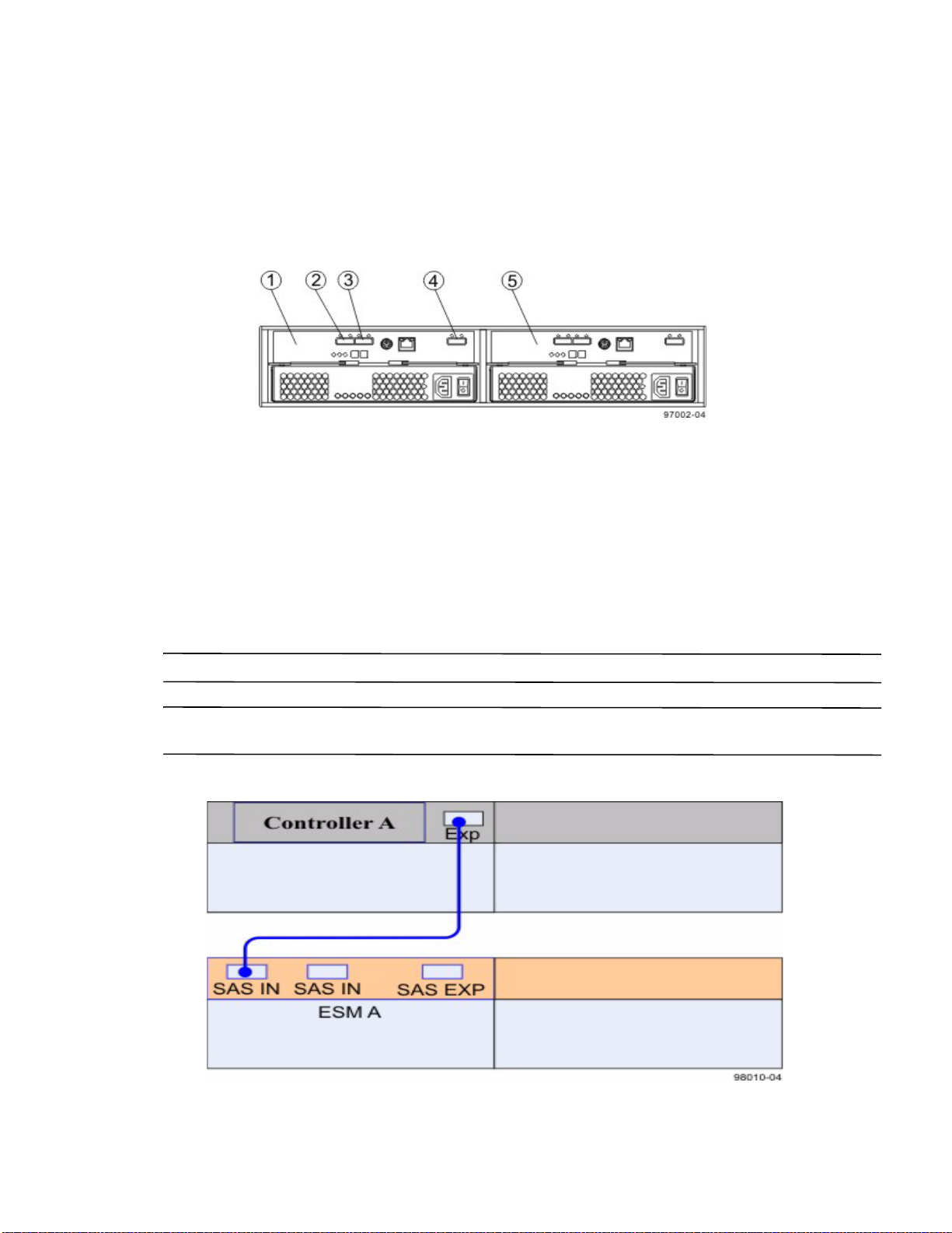
Things to Know – Drive Trays with the E2600 Controller-Drive Tray
Each DE1600 drive tray can contain a maximum of twelve 8.89-cm (3.5-in.) drives.
Each DE5600 drive tray can contain a maximum of twenty-four 6.35-cm (2.5-in.) drives.
The ESMs on the DE1600 drive tray and the DE5600 drive tray contain two sets of In connectors and one set
of Out connectors.
Figure 77 DE1600 Drive Tray and DE5600 Drive Tray – Rear View
1. ESM A
2. SAS Connector 1 (In)
3. SAS Connector 2 (In)
4. Expansion Connector (Out)
5. ESM B
Things to Know – Drive Tray Cabling Configurations – Simplex System
The following figure shows an example of cable configurations from the simplex E2600 controller-drive tray to
either a DE1600 drive tray or a DE5600 drive tray. Use this example as a guide to connect cables in your storage
array.
NOTE You can use either SAS IN connector on a drive tray for cabling.
NOTE Configurations for connecting cables in a simplex system do not provide for tray loss protection. Loss of a
drive tray that has a second drive tray connected to it means that you cannot access the second drive tray.
Figure 78 Controller-Drive Tray Above the Drive Tray
82 E2600 Controller-Drive Tray Installation Guide
Page 91
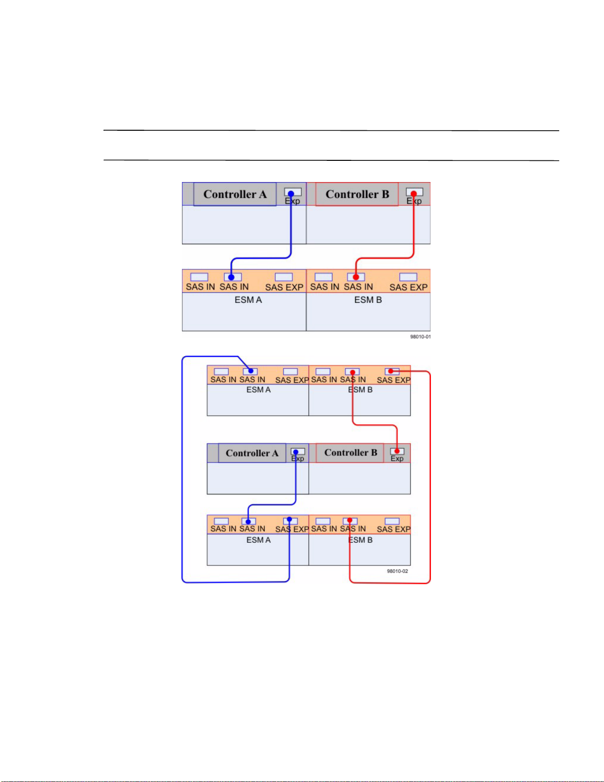
Things to Know – Drive Tray Cabling Configurations – Duplex System
The figures in this topic show examples of cable configurations from the controller-drive tray to the drive trays. Use
these examples as guides to connect cables in your storage array.
NOTE The configuration shown in the fourth image in this topic provides an example of tray loss protection. With
tray loss protection, if one drive tray cannot be accessed, you still have access to the remaining drive trays.
Figure 79 Controller-Drive Tray Above the Drive Tray
Figure 80 Controller-Drive Tray Between Two Drive Trays
E2600 Controller-Drive Tray Installation Guide 83
Page 92
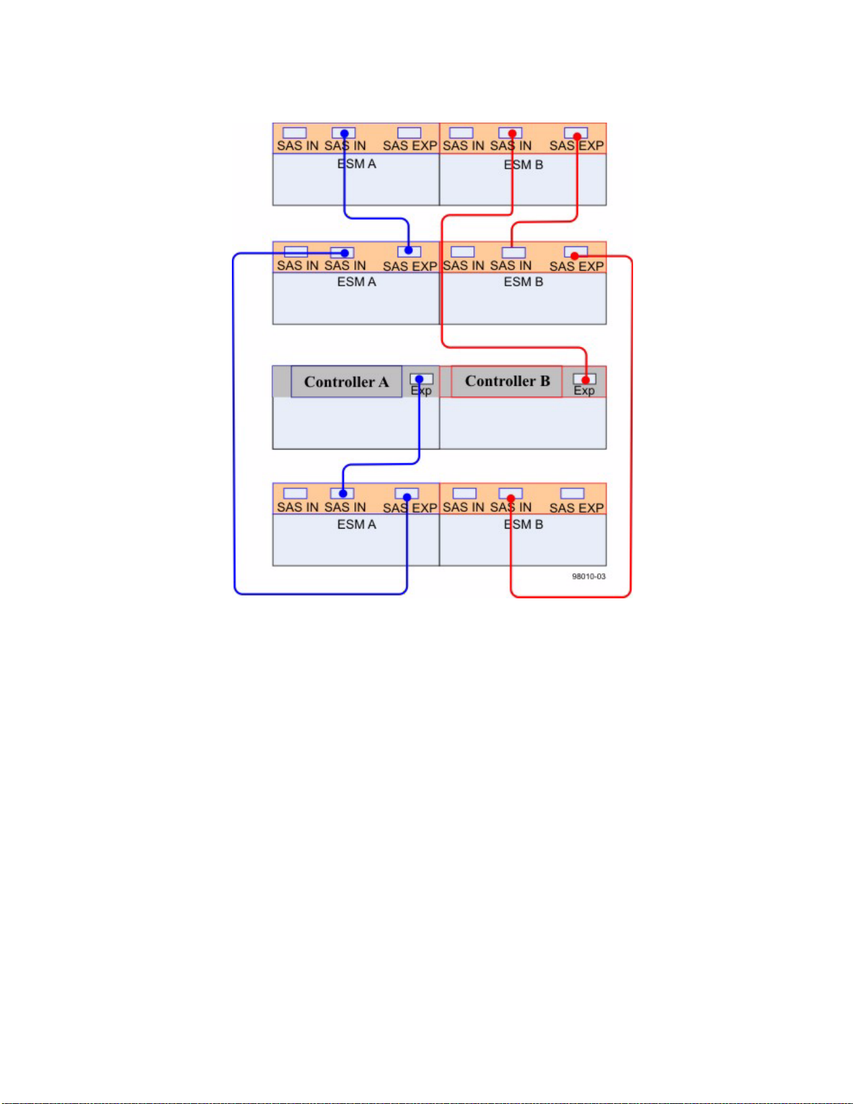
Figure 81 Controller-Drive Tray with Three Drive Trays
84 E2600 Controller-Drive Tray Installation Guide
Page 93
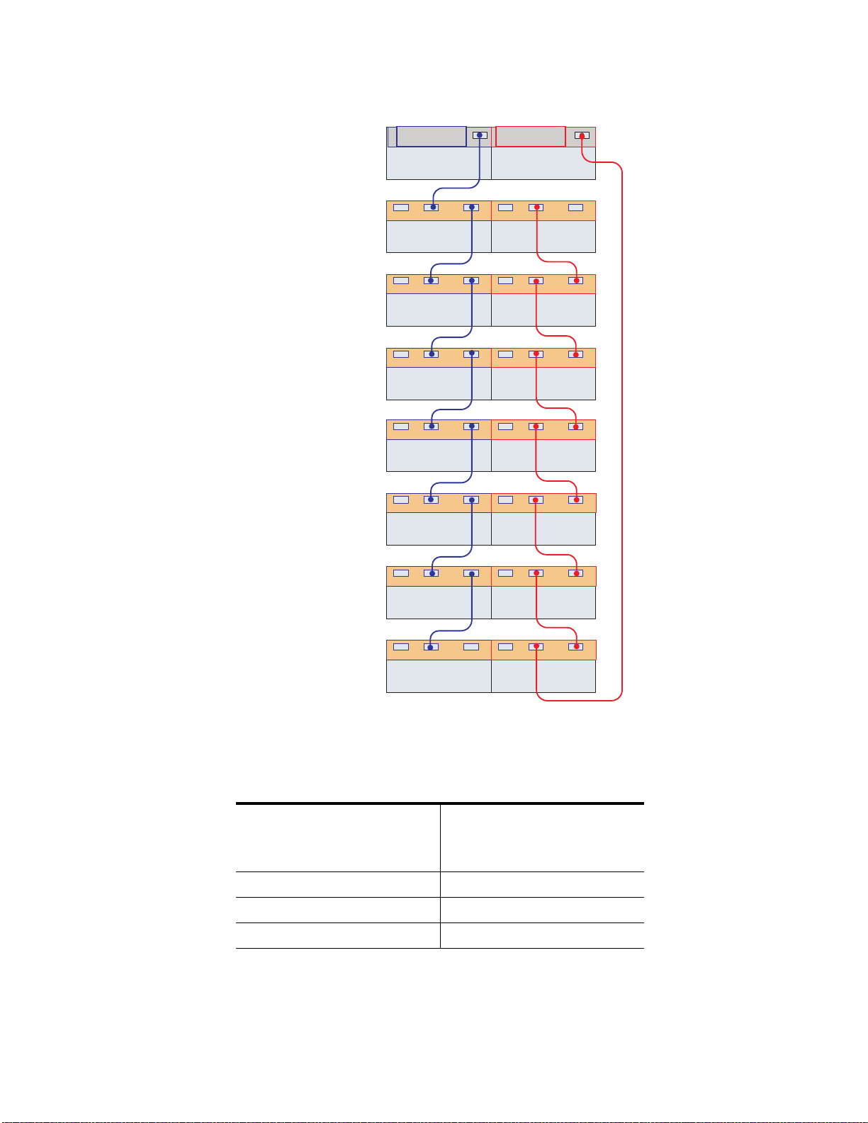
Figure 82 Connecting Cables for Maximum Redundancy and Tray Loss Protection
1A 1B 2A 2B
ESM A ESM B
1A 1B 2A 2B
ESM A ESM B
1A 1B 2A 2B
ESM A ESM B
1A 1B 2A 2B
ESM A ESM B
1A 1B 2A 2B
ESM A ESM B
1A 1B 2A 2B
ESM A ESM B
Exp
Chamonix A Chamonix B
Exp
1A 1B 2A 2B
Controller A Controller B
98002-03
ESM A ESM B
SAS EXP SAS EXP
SAS IN SAS IN SAS IN SAS IN
SAS EXP SAS EXP
SAS IN SAS IN SAS IN SAS IN
SAS EXP SAS EXP
SAS IN SAS IN SAS IN SAS IN
SAS EXP SAS EXP
SAS IN SAS IN SAS IN SAS IN
SAS EXP SAS EXP
SAS IN SAS IN SAS IN SAS IN
SAS EXP SAS EXP
SAS IN SAS IN SAS IN SAS IN
SAS EXP SAS EXP
SAS IN SAS IN SAS IN SAS IN
You can use up to eight
trays in a storage array.
Procedure – Connecting the DE1600 Drive Trays and the DE5600 Drive Trays
1. Use the following table to determine the number of SAS cables that you need.
Table 13 Drive Tray Cables
Number of Drive Trays that
You Plan to Connect to the
Controller-Drive Tray
12
Number of Cables Required
24
36
E2600 Controller-Drive Tray Installation Guide 85
Page 94
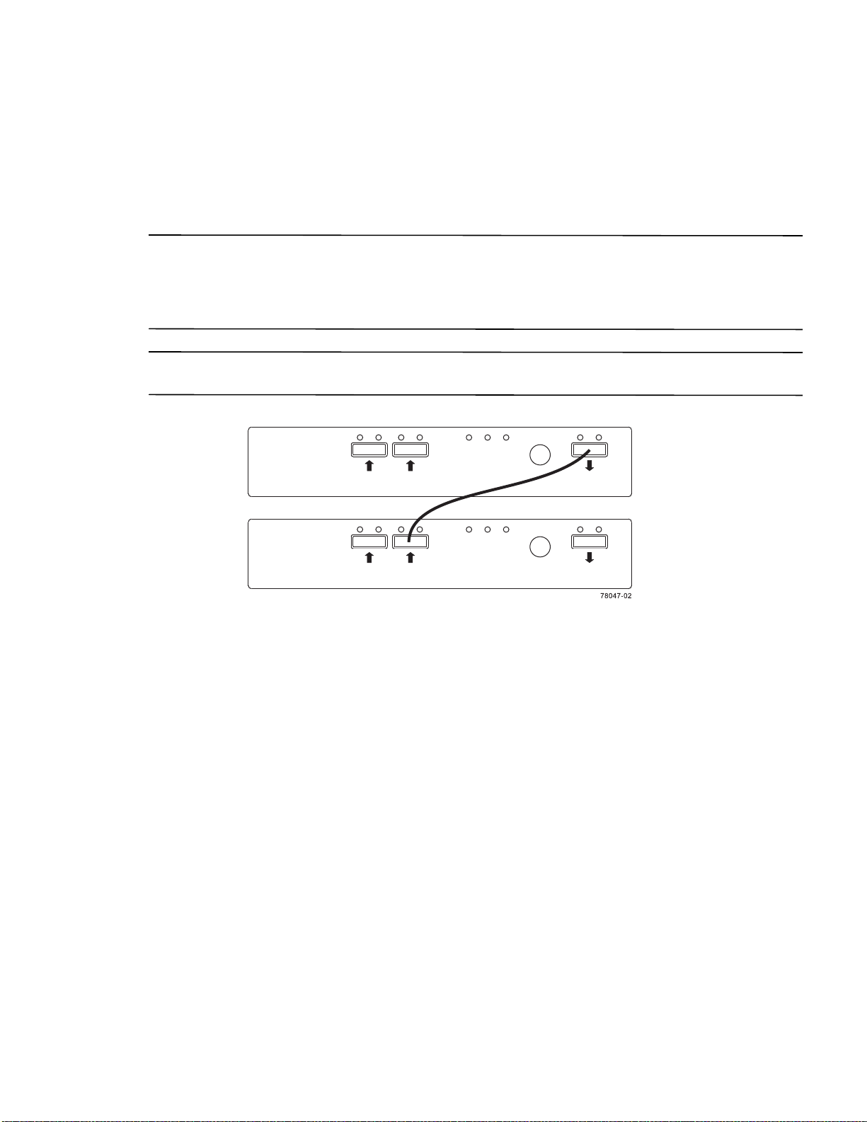
2. If there is a black, plastic plug in the SAS expansion connector of the controller, remove it.
3. Insert one end of the cable into the SAS expansion connector on the controller in slot A in the controller-drive
tray.
4. Insert the other end of the cable into the connector with an up arrow on the ESM in slot A in the drive tray.
5. Are you adding more drive trays?
NOTE Each ESM in a drive tray has three expansion connectors: two on the left-center of the ESM and one in the
upper-right side. When connecting from an ESM in one drive tray to an ESM in another drive tray, make sure that
you connect the connector on the upper-right to one of the connectors on the left-center. The following figure shows
these arrows on an ESM. If the cable is connected either between the two left-center ESM connectors or between
two upper-right ESM connectors, communication between the two drive trays is lost.
NOTE It does not matter which of the two left-center ESM connectors you use to connect to the expansion
connector on the far-right side.
Figure 83 Connecting a Cable from One ESM to a Second ESM
— Ye s – Go to step 6.
— No – Go to step 9.
6. In the ESM in the first drive tray, insert one end of the cable into the connector
on the far-right side.
7. In the ESM in the next drive tray, insert the other end of the cable into one of the connectors in the left-center
of the ESM.
8. Repeat step 6 through step 7 for each drive tray that you intend to add to the storage array.
9. To each end of the cables, attach a label with this information:
— The controller ID (for example, controller A)
— The ESM ID (for example, ESM A)
— The ESM connector (In or Out)
— The drive tray ID
86 E2600 Controller-Drive Tray Installation Guide
Page 95
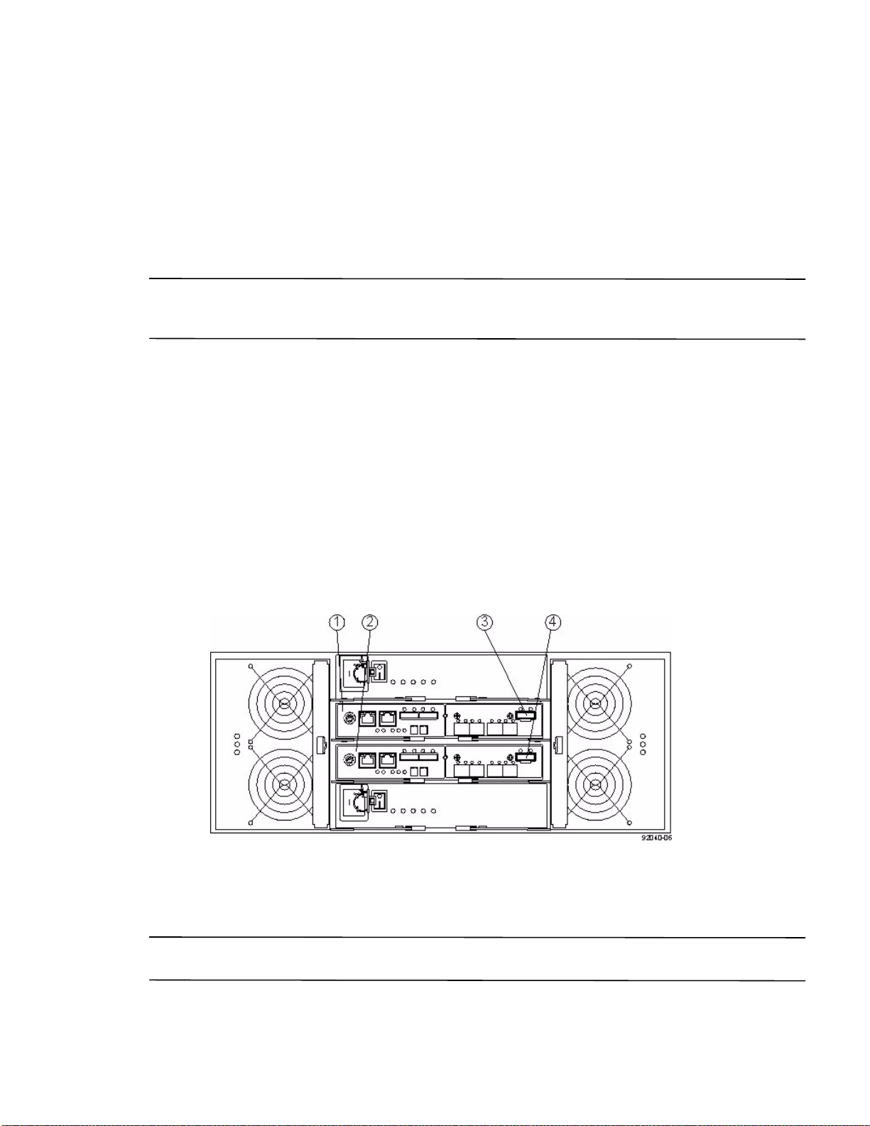
For example, if you are connecting controller A to the In connector on ESM A in drive tray 1, the label on the
controller end of the cable has this info
rmation:
CtA-Dch1, Dm1-ESM_A (left), In – Controller End
The label on the drive tray end of the cable has this information:
Dm1-ESM_A (left), In, CtrlA
10. If you are installing the controller-drive tray with two controllers, repeat step 2 through step 9 for the controller
in slot B in the controller-drive tray.
NOTE To connect cables for maximum redundancy, the cables attaching controller B must be connected to the
drive trays in the opposite tray order as for controller A. That is, the last drive tray in the chain from controller A
must be the first drive tray in the chain from controller B.
Things to Know – E2660 Controller-Drive Tray
On the E2660 controller-drive tray, each controller has a pair of levers with handles for removing the controller
from the controller-drive tray. One of these handles on each controller is located next to a host connector. The close
spacing between the handle and the host connector might make it difficult to remove a cable that is attached to the
host connector. If this problem occurs, use a flat-blade screwdriver to push in the release component on the cable
connector.
The E2660 controller-drive tray supports the DE6600 drive tray for expansion.
The maximum number of drive slots in the storage array is 180 drive slots, including up to 60 drive slots in the
controller-drive tray. Exceeding 180 drive slots makes the storage array invalid. The controllers cannot perform
operations that modify the configuration, such as creating new volumes.
Each controller has one dual-ported SAS expansion connector to connect to the drive trays.
Figure 84 Drive Channel Ports on the E2660 Controller-Drive Tray – Rear View
1. Controller A Canister
2. Controller B Canister
3. Controller A SAS Expansion Connector
4. Controller B SAS Expansion Connector
NOTE To maintain data access in the event of the failure of a controller, an ESM, or a drive channel, you must
connect a drive tray or a string of drive trays to both drive channels on a redundant path pair.
E2600 Controller-Drive Tray Installation Guide 87
Page 96
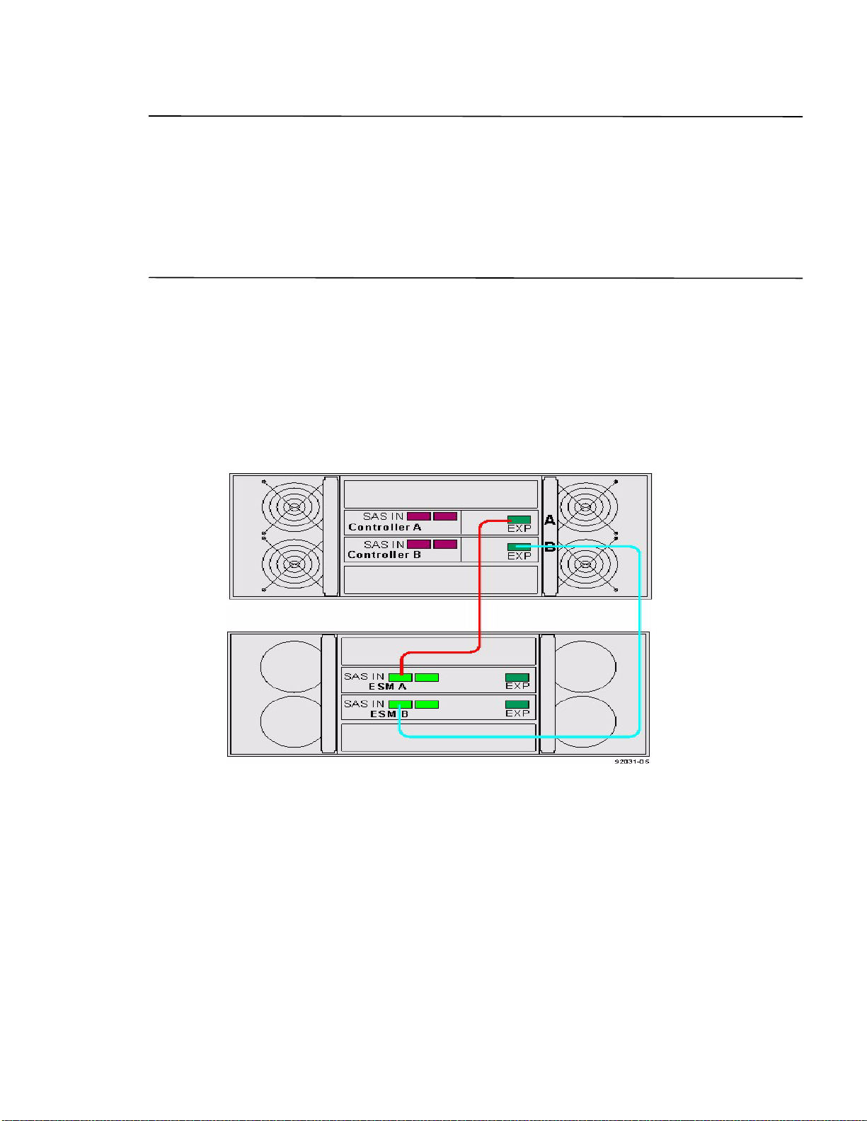
ATTENTION Potential damage to equipment (Network Telecommunications Equipment (NEBS) Ethernet
cable installations only) – The intra-b
connection to intra-building or unexposed wiring or cabling only. The intra-building port(s) of this equipment must
be metallically connected to interfaces that connect to the Outside Plant (OSP) or its wiring. These interfaces are
designed for use as intra-building interfaces only (Type 2 or Type 4 ports as described in GR-1089-CORE) and
require isolation from the exposed OSP cabling. The addition of Primary Protectors is not sufficient protection in
order to connect these interfaces metallically to OSP wiring. The cable shall be shielded Twisted Pair (STP) and must
be grounded at both ends to meet the intra-building lightning requirements from section 4.6.9.2 of GR-1089-CORE,
Issue #5.
uilding port(s) (Ethernet maintenance ports) of this equipment is suitable for
Things to Know – Drive Trays with the E2660 Controller-Drive Tray
Each DE6600 drive tray can contain a maximum of sixty 8.89-cm (3.5-in.) drives housed with five drawers of 12
drives each.
Things to Know – E2660 Drive Tray Cabling Configurations – Duplex System
The figures in this topic show examples of cable configurations from the controller-drive tray to the drive trays. Use
these examples as guides to connect cables in your storage array.
Figure 85 Controller-Drive Tray Above the Drive Tray
88 E2600 Controller-Drive Tray Installation Guide
Page 97
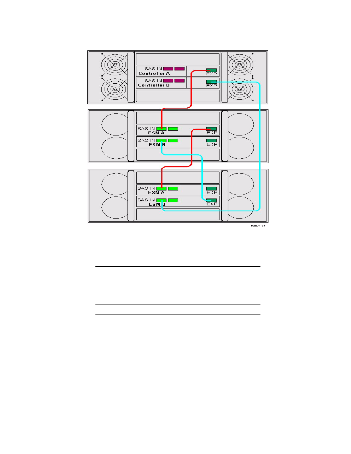
Figure 86 Controller-Drive Tray Between Two Drive Trays
Procedure – Connecting the DE6600 Drive Tray
1. Use the following table to determine the number of SAS cables that you need.
Table 14 Drive Tray Cables
Number of Drive Trays that
You Plan to Connect to the
Controller-Drive Tray
12
24
2. If there is a black, plastic plug in the SAS expansion connector of the controller, remove it.
3. Insert one end of the cable into the SAS expansion connector on the controller in slot A in the controller-drive
tray.
4. Insert the other end of the cable into the connector with an up arrow on the ESM in slot A in the drive tray.
5. Are you adding more drive trays?
Number of Cables Required
E2600 Controller-Drive Tray Installation Guide 89
Page 98
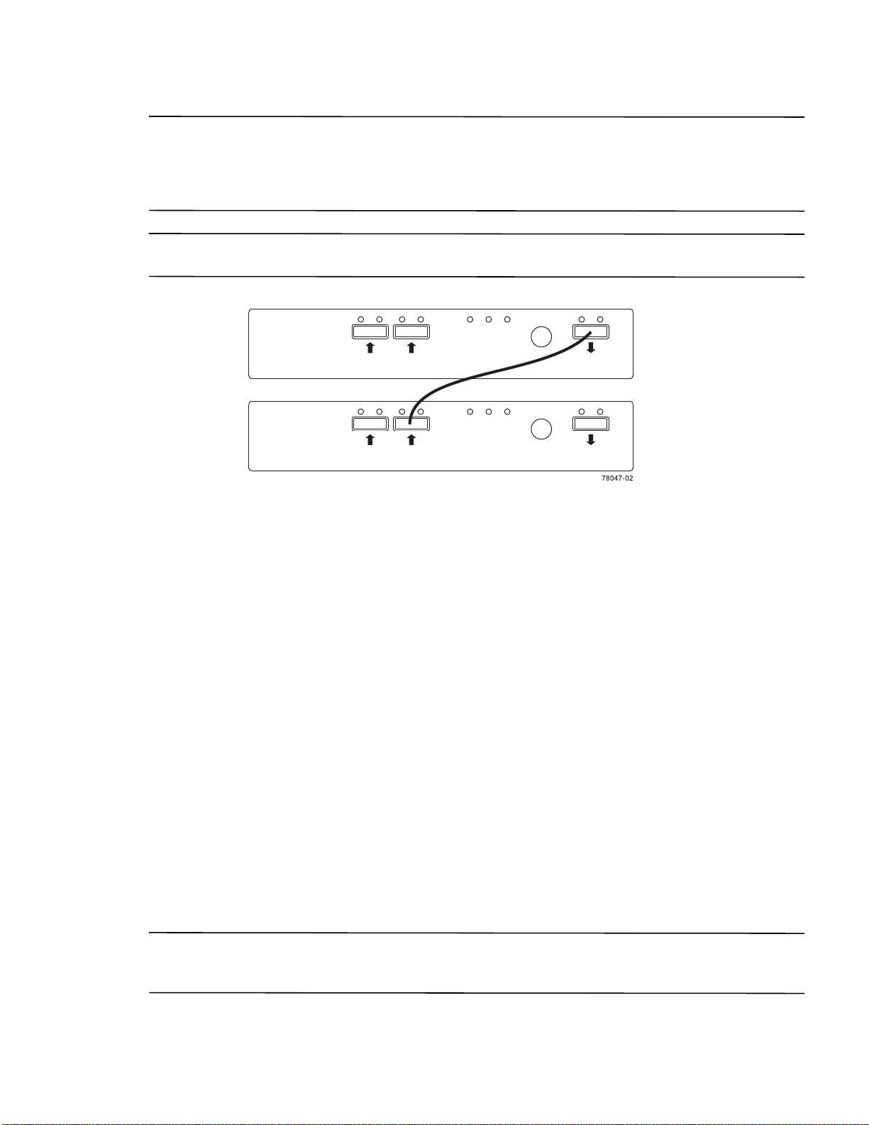
NOTE Each ESM in a drive tray has three expansion connectors: two on the left-center of the ESM and one in the
upper-right side. When connecting from an ESM in one drive tray to an ESM in another driv
e tray, make sure that
you connect the connector on the upper-right to one of the connectors on the left-center. The following figure shows
these arrows on an ESM. If the cable is connected either between the two left-center ESM connectors or between
two upper-right ESM connectors, communication between the two drive trays is lost.
NOTE It does not matter which of the two left-center ESM connectors you use to connect to the expansion
connector on the far-right side.
Figure 87 Connecting a Cable from One ESM to a Second ESM
— Ye s – Go to step 6.
— No – Go to step 9.
6. In the ESM in the first drive tray, insert one end of the cable into the connector
on the far-right side.
7. In the ESM in the next drive tray, insert the other end of the cable into one of the connectors in the left-center
of the ESM.
8. Repeat step 6 through step 7 for each drive tray that you intend to add to the storage array.
9. To each end of the cables, attach a label with this information:
— The controller ID (for example, controller A)
— The ESM ID (for example, ESM A)
— The ESM connector (In or Out)
— The drive tray ID
For example, if you are connecting controller A
to the In connector on ESM A in drive tray 1, the label on the
controller end of the cable has this information:
CtA-Dch1, Dm1-ESM_A (left), In – Controller End
The label on the drive tray end of the cable has this information:
Dm1-ESM_A (left), In, CtrlA
10. If you are installing the controller-drive tray with two controllers, repeat step 2 through step 9 for the controller
in slot B in the controller-drive tray.
NOTE To connect cables for maximum redundancy, the cables attaching controller B must be connected to the
drive trays in the opposite tray order as for controller A. That is, the last drive tray in the chain from controller A
must be the first drive tray in the chain from controller B.
90 E2600 Controller-Drive Tray Installation Guide
Page 99

Step 8 - Connecting the Ethernet Cables
Key Terms
in-band management
A method to manage a storage array in which a storage management station sends commands to the storage array
through the host input/output (I/O) connection to the controller.
out-of-band management
A method to manage a storage array in which a storage management station sends commands to the storage array
through the Ethernet connections on the controller.
Things to Know – Connecting Ethernet Cables
ATTENTION Risk of security breach – Connect the Ethernet ports on the controller tray to a private network
segment behind a firewall. If the Ethernet connection is not protected by a firewall, your storage array might be at
risk of being accessed from outside of your network.
These Ethernet connections are intended for out-of-band management and have nothing to do with the iSCSI
host interface cards (HICs), whether 1Gb/s or 10Gb/s.
Ethernet port 2 on each controller is reserved for access by your Technical Support representative.
In limited situations in which the storage management station is connected directly to the controller tray, you
must use an Ethernet crossover cable. An Ethernet crossover cable is a special cable that reverses the pin
contacts between the two ends of the cable.
Procedure – Connecting Ethernet Cables
Perform these steps to connect Ethernet cables for out-of-band management. If you use only in-band management,
skip these steps.
1. Connect one end of an Ethernet cable into the Ethernet port 1 on controller A.
2. Connect the other end to the applicable network connection.
3. Repeat step 1 through step 2 for controller B.
E2600 Controller-Drive Tray Installation Guide 91
Page 100

E2600 Controller-Drive Tray Installation Guide 92
 Loading...