

Page 1
ATTENTION Possible equipment damage – Do not place any
object on top of cabinet-mounted devices.
IMPORTANT: The installation order within each drawer is from left-toright in each row. You must install a drive in slots 1, 4, 7, and 10. Make
sure that the four drives in each row are adjacent to each other. The
long edge of each drive should touch the drive next to it. To maintain
a uniform airfl ow across all drawers, the drive tray must be confi gured
with a minimum of four drives in the front of each row in the drive
drawer.
NOTE: The drive drawers ship installed in the DE6900 drive tray, but
the drives ship separately from the drive drawers.
4
Install the drives
Before you begin
1
For warnings, refer to the printed Safety Notices
document.
For detailed installation instructions, refer to CE7900 Controller Tray
Installation Guide.
What you need for assembly:
DE6900 drive tray (for connection to a CE7900 controller
tray):
• One four-unit (4U) -high DE6900 drive tray
• Two DVDs:
– Firmware DVD
– SANtricity™
ES Storage Manager Installation DVD, which
contains all of the documents referred to in this guide,
except for the quick install guides.
• Two Small Form-factor Pluggable (SFP) transceivers
• One cabinet-mounting hardware kit
Options:
• Drives (four minimum for each drive drawer or 20 minimum for
the drive tray)
• Two SFP transceivers for each fi ber -optic cable
• Two fi ber-optic cables or two copper cables for each drive tray
connection
• One rail-mounting hardware kit
If you have any questions about the fi rmware or your confi guration,
contact your Customer and Technical Support representative.
Tools:
• A medium fl at-blade screwdriver
• A No. 2 Phillips screwdriver
• Anti-static protection
• Labels – To help you to identify cable connections and to trace
cables more easily
• A cart – To hold the drive tray and its components
• A fl ashlight
1.1
1
1
NOTE Make sure that each drive drawer in the DE6900 drive tray is
securely fastened to ensure correct air fl ow to the drives.
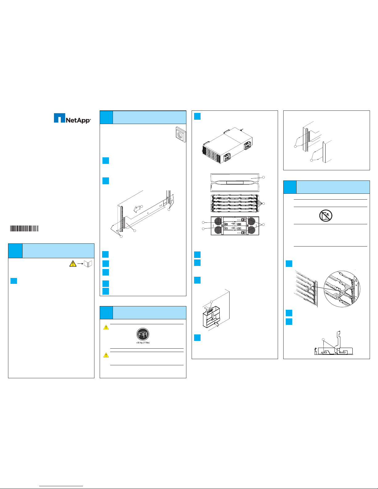
1. Four screws for securing the front of the DE6900 drive tray.
DE6900 Drive Tray with Drive Handles
1. Front Bezel
2. Drive Drawers
3. Power Supply
4. ESM A
5. ESM B
!
2
1
!
1
3
4
5
DE6900 Drive Tray – Front and Rear View
Quick Install Guide
for the DE6900 Drive Tray
52987- 00A
Storage System
Install the mounting rails
2
You can install the drive tray into an industry-standard cabinet.
There must be a minimum depth of 76 cm (30 in.) between the front
EIA support rails and the rear EIA support rails.
Position the mounting rails in the cabinet.
• If you are installing the mounting rails above an existing tray,
position the mounting rails directly above the tray.
• If you are installing the mounting rails below an existing tray,
allow 17.8-cm (7-in.) vertical clearance for the DE6900 drive tray.
From the front of the cabinet with the mounting-rail fl anges inside of
the cabinet’s mounting rail assemblies, place the mounting rail inside
the cabinet, and extend the mounting rail until the fl anges on the
mounting rail touch the inside of the cabinet.
2.1
1
2
3
4
1. Front of the Mounting Rail
2. Two M4 Screws for the Rear EIA Support Rail
3. Front of the Cabinet
4. Two M5 Screws for the Front EIA Support Rail
From the rear of the cabinet, use the Phillips screwdriver to loosely
tighten the two screws. Do not completely tighten the screws until you
have installed the DE6900 drive tray in the cabinet.
2.2
NOTE If the cabinet where you are installing the DE6900
drive tray contains square holes rather than round holes,
you will want to use the shoulder screw provided for in the
rail-mounting hardware kit.
2.7
Insert one M5 screw through the front of the cabinet, and screw it into
the top captured nut in the mounting rail.
Insert two M4 screws through the rear of the cabinet, and screw them
into the captured nuts in the rear fl ange in the mounting rail, and
tighten the adjustment screws on the mounting rail.
Repeat step 2.3 through step 2.5 to install the second mounting rail.
Insert one M5 screw through the front of the mounting rail. This screw
will attach the DE6900 drive tray to the cabinet.
2.6
2.4
2.5
With the help of at least two other persons, remove the DE6900 drive
tray and all of the contents from the shipping carton, using the four
drive tray handles as shown.
3.1
3.4
3.3
Remove the front bezel by grasping the sides and pulling the bezel
toward you. Set it aside.
With the help of a mechanized lift or at least two other persons,
place the rear of the DE6900 drive tray on the mounting rails. Slide
the DE6900 drive tray into the cabinet, and verify that the rear of the
DE6900 drive tray is secured by the hold-down clips at the rear of each
mounting rail.
After the DE6900 drive tray is correctly aligned, use your thumb to
unlatch the four drive tray handles (two to a side), and remove the drive
tray handles from the DE6900 drive tray, from the rear to the front.
3.2
2
4
1
3
1. Thumb Latch
2. Pull the thumb latch away from the drive
tray to detach the hook.
3. Shift the drive tray handle down to release
the other four hooks.
4. Move the drive tray handle away from the
drive tray.
3.5
Secure the side of the DE6900 drive tray to the cabinet. Use the four
10-32 screws to attach the fl ange on each side of the DE6900 drive
tray to the mounting rails.
NOTE Make sure that each drive drawer in the DE6900 drive tray is
securely fastened to ensure correct air fl ow to the drives.
4.3
Pull on the extended levers to pull the drive drawer out to its full
extension without removing it from the drive tray.
Starting with the fi rst drive, raise the drive handle to the vertical
position, and align the raised button on each side over the matching
gap in the drive channel on the drive drawer.
4.2
4.1
Starting with the top drive drawer in the DE6900 drive tray, release
the levers on each side of the drive drawer by pulling both towards the
center.
10
11
12
10
11
12
10
11
12
10
11
12
10
11
12
10
11
12
10
11
12
10
11
12
1
1. Raised Buttons
3
Install the drive tray
WARNING (W08) Risk of bodily injury –
Three persons are required to safely lift the component.
WARNING (W08) Risk of bodily injury – An empty tray weighs
approximately 56.7 kg (125 lb). Three persons are required to safely
move an empty tray. If the tray is populated with components, a
mechanized lift is required to safely move the tray.
NOTE Make sure you do not install the drives in the drive tray until you
have moved it into the cabinet.
2.3
Page 2
8
Install the software
In the AMW, select the Setup tab. If the storage array is in the Optimal
state, perform these tasks:
Confi gure the storage array.
Defi ne the hosts.
Create new storage partitions.
Select the Support tab, and click the Gather Support Information
link.
To set or change a password, in the AMW, select either the
Set a Storage Array Password link under the Setup tab, or select
Storage Array >> Security >> Set Password.
11.1
11.2
11.3
11.4
11.5
Confi gure the
storage array
11
6
Turn on the power
ATTE NT ION Risk of bodily injury – Each tray has more
than one power cord. To remove all electrical current from
the devices, make sure that all of the power cords are
disconnected from the power source.
March 2012
NetApp Inc.
495 East Java Drive
Sunnyvale, CA 94089 U.S .A.
Telephone: + (408) 822-6000
Fax: +1 (408) 822-4501
Support telephone: +1 (888) 4 -NETAPP
Document comments: [email protected] om
Information Web: http://w ww.netapp.com
Part Number: 52987-00 , Rev. A
Copyright © 2012 NetApp, Inc . All rights reserved.
5.4
On the CE7900 controller tray, connect the fi ber-optic cable on the
copper cable from drive port 3 of controller B to port 1B on the lower
ESM of the second DE6900 drive tray.
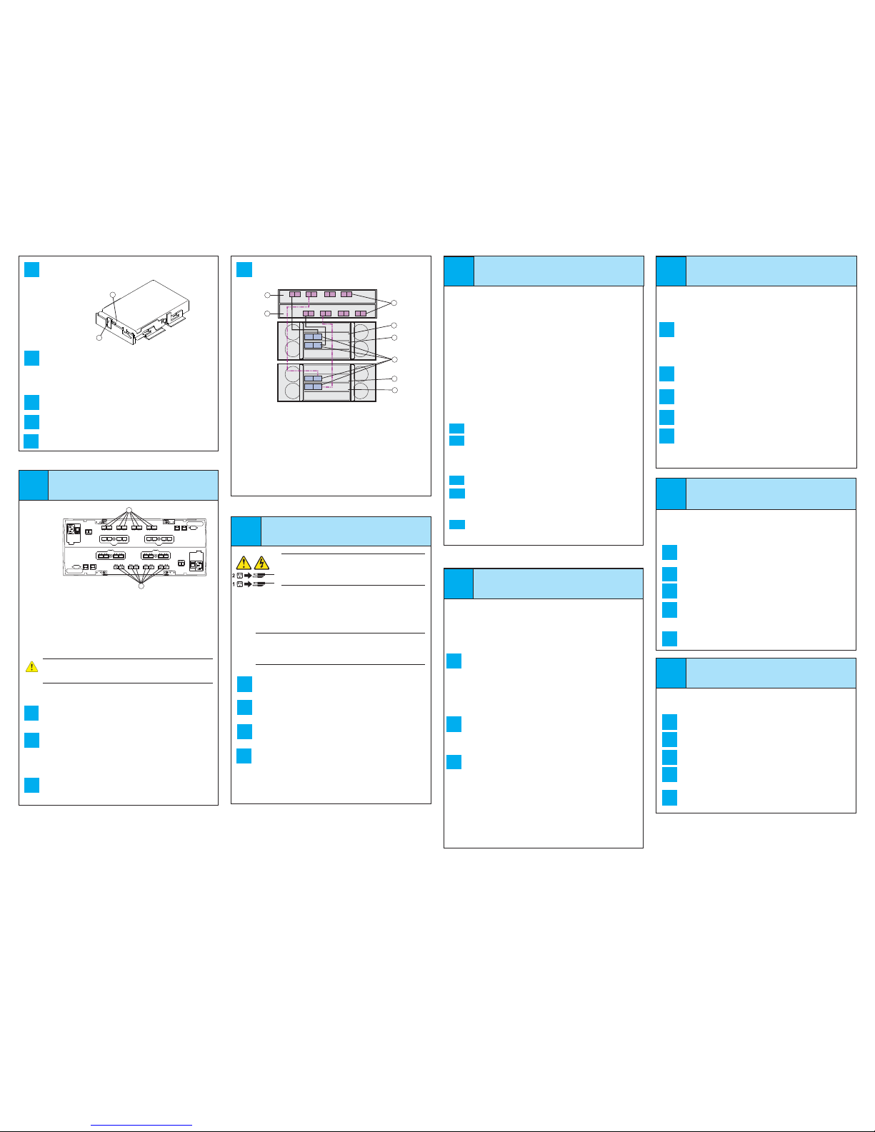
1. Controller A (Inverted)
2. Controller B
3. Top ESMs on the Drive Tray
4. Bottom ESMs on the Drive Tray
5. ESM Port 1B, two per Drive Tray
6. Drive Ports on Controller A and Controller B
For information about other standard basic cabling confi gurations,
refer to either the CE7900 Controller Tray Installation Guide or the
Hardware Cabling Guide.
For information about all drive-side trunking confi gurations, refer to the
Hardware Cabling Guide.
6
8
5
7
4
2
1
3
1A 1B
A
B
1A 1B
1A 1B
A
B
1A
1B
8
6
5
7
4
2
1
3
1
2
3
4
5
6
3
4
4.7
Install the other drives in rows from left-to-right, front-to-back, until the
drive drawer is fully populated.
NOTE: The maximum number of drives in a confi guration is 480,
(12 drives in each drive drawer of a fi ve-drive drawer drive tray and a
maximum of eight drive trays).
Push the drive drawer all the way back into the drive tray, closing the
levers on each side of the drive drawer.
Continue with the next drive drawer, repeating step 4.1 through
step 4.6 for each drive drawer in the confi guration.
Attach the bezel onto the front of the DE6900 drive tray.
4.6
4.5
Lower the drive straight down, and rotate the drive handle down until
the drive snaps into place under the drive release lever.
4.4
1. Drive Release Lever
2. Drive Handle
1
2
Connect the cables
5
NOTE If not already installed, insert SFP transceivers into the required
drive ports on the CE7900 controller tray and the DE6900 drive ports
on the drive trays. Remove any extra SFP transceivers from the drive
ports that will not be used.
WARNING (W03) Risk of exposure to laser radiation – Do not
disassemble or remove any part of a Small Form-factor Pluggable
(SFP) transceiver because you might be exposed to laser radiation.
1 2 3 4 5 6 7 8
1 2 3 4 5 6 7 8
Controller A
(inverted)
Controller B
1
2
1 Drive Ports 8 through 1 on Controller A
2 Drive Ports 1 through 8 on Controller B
5.3
Steps to Connect one DE6900 Drive Tray in Standard Basic
Cabling:
Starting with the CE7900 controller tray, connect the fi ber-optic cable
or the copper cable from drive port 8 of controller A to port 1B on the
upper ESM of the fi rst DE6900 drive tray.
On the CE7900 controller tray, connect the fi ber-optic cable or the
copper cable from drive port 1 of controller B to port 1B on the lower
ESM of the fi rst DE6900 drive tray.
Steps to Connect a Second DE6900 Drive Tray in Standard
Basic Cabling:
Starting with the CE7900 controller tray, connect the fi ber-optic cable
or the copper cable from drive port 6 of controller A to port 1B on the
upper ESM of the second DE6900 drive tray.
5.1
5.2
You must follow the power sequence in the order shown. To establish
power redundancy for trays with two power supplies, use at least two
different power distribution units (PDUs) in the cabinet. Split the power
connections from each tray into the separate PDUs. Then connect the
PDUs to external power receptacles that are on different circuits.
IMPORTANT You must turn on the power to all connected drives
before you turn on the power for the controller tray. Performing this
action makes sure that the controllers recognize each attached
DE6900 drive tray.
Turn off all of the Power switches from the rear of the storage array,
and make sure that all of the power cords are connected.
If the main circuit breaker switches in the cabinet are not already
turned on, turn on the circuit breaker switches.
Turn on the Power switch on each power-fan canister in all of the
newly installed drive trays.
Turn on the Power switch on each power-fan canister in the
controller tray.
NOTE When turning off the power to the storage array, perform the
procedure in the reverse order. Turn off the power fi rst to the CE7900
controller tray, and then turn off the power to the DE6900 drive trays.
6.1
6.2
6.3
6.4
8.1
8.2
8.3
Two types of computers are associated with the storage array.
• Hosts send I/O to the storage array.
• Management stations manage the storage array.
The type of operating system that the management station runs is the
directory that you need to locate on the DVD.
At this time, check your current Fibre Channel host bus adapters’
(HBAs’) BIOS, and device driver versions, and, if necessary, update
them before proceeding. For HBAs, obtain the BIOS and device
drivers directly from the vendor.
For Microsoft Windows installations,
• Install the StorPort device driver.
• Install the MPIO multi-path driver on the host.
On the SANtricity ES Storage Manager Installation DVD, locate the
appropriate operating system (OS) directory.
• Review the appropriate operating system and device driver
readme fi les included on the SANtricity ES Storage Manager
Installation DVD for additional information.
Launch the SMIA executable fi le. Follow the instructions in the wizard,
and select one of these installation methods:
• For the Management Station designated as a monitor (for
monitoring and sending alert notifi cations ) , sel e ct Management
Station (full installation), and, when prompted, click
Automatically Start Monitor.
• For the Management Station that you will use to manage
the storage array, select Management Station, and, when
prompted, select Do Not Automatically Start the Monitor.
• For all I/O hosts attached to the storage array, select Host,
and, when prompted, select Do Not Automatically Start the
Monitor.
10.1
10.2
10.3
10.4
Perform a basic setup
10
In the AMW, select the Setup tab, and select the Rename
Storage Array link to name the storage array. You can use up
to 30 alphanumeric characters, hyphens (-), pound signs (#), and
underscores (_).
Also on the Setup tab, click the Locate Storage Array link to fi nd
the storage array in the cabinet. A white LED blinks on the front of the
selected storage array. Physically label the storage array with its name.
Click the Storage & Copy Services tab to see the storage array’s
confi guration.
If the storage array is not in the Optimal state, click the Needs
Attention link. Follow the steps in the Recovery Guru.
Select the Summary tab, and select Storage Array Profi le.
By clicking the tabs, fi nd the controller fi rmware, NVSRAM, ESM
fi rmware, drive product ID, and fi rmware version, and record them.
Close the storage array profi le.
10.5
9
Discover the storage
array
Before performing this step, make sure that you have correctly
confi gured the storage array IP addresses as described in the Initial
Confi guration and Software Installation Guide for SANtricity ES
Storage Manager.
Start the SANtricity ES Storage Manager software from your
management station either by typing SMclient and pressing
Enter (UNIX OSs), or by navigating to the directory that contains
the SMclient.exe fi le, typing SMclient and pressing Enter
(Windows OSs). The client software starts and shows the Enterprise
Management Window (EMW).
Select Tools >> Automatic Discovery from the EMW to discover the
storage array.
In the confi guration dialog, click OK to start the automatic discovery.
Click the Devices tab of the EMW to see the storage arrays.
Double-click the storage array that you want to manage. The
associated Array Management Window (AMW) is launched.
NOTE To add storage from outside the local subnetwork, use the
manual discovery method. From the EMW, click the Add Storage
Arrays link, and follow the instructions.
9.5
9.4
9.3
9.2
9.1
For more information, refer to the “Deciding on the Management
Method” step in the Initial Confi guration and Software Installation
Guide for SANtricity ES Storage Manager.
For Out-of-band management, use one of the methods below to
confi gure the controllers for network connectivity:
Without a DHCP server
Connect separate Ethernet cables to each controller.
Manually confi gure the network settings on the controllers, using
the guidelines and procedures from the “Manually Confi guring the
Controllers” step in the Initial Confi guration and Software Installation
Guide for SANtricity ES Storage Manager.
With a DHCP server
Connect separate Ethernet cables to each controller.
Assign static IP addresses to the controllers.
NOTE This method applies only to IPv4 networks.
Stateless Address Autoconfi guration
Connect separate Ethernet cables to each controller.
NOTE This method applies only to IPv6 networks and does not require
either a DHCP server or a router.
Both management methods are specifi c to the installation steps in
Section 9. This section and those that follow concern confi guration of
the entire storage array.
• In-band management – Managing a storage array by using a
storage management station to send commands through the host
input/output (I/O) connection to the controller.
• Out-of-band management – Managing a storage array by using
a storage management station to send commands through the
Ethernet connections on each controller.
7
Determine the
management method
7.a1
7.a 2
7.b1
7.b2
7.c1
4.8
 Loading...