

Page 1
Prepare for installation
Install hardware Install disk shelves Connect cables
Complete system setup
AltaVault System
Installation and Setup Instructions
1 3 4 5
2
Prepare for installation | 1
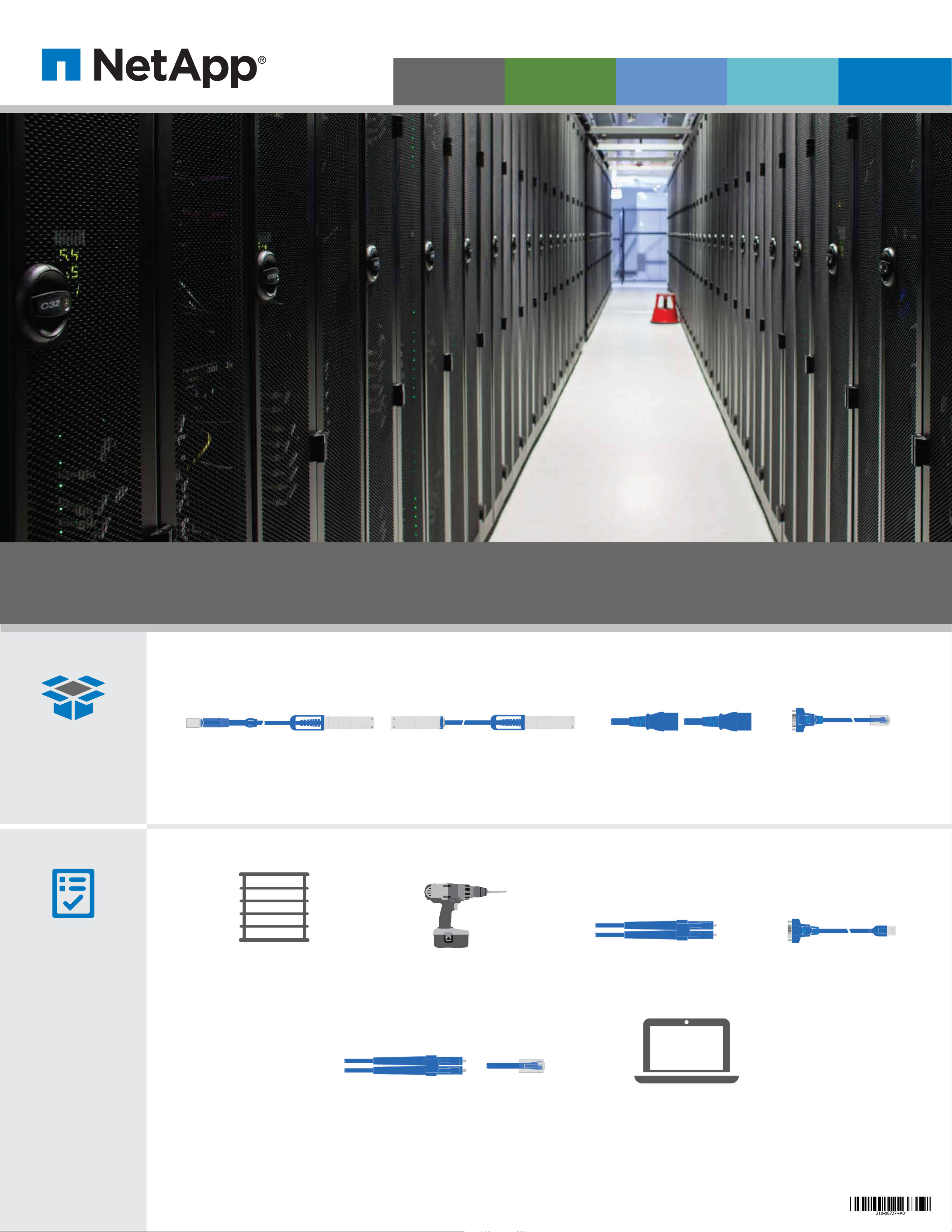
In the box
mini SAS HD-QSFP cable
(controller to shelf)
QSFP-QSFP cable
(shelf to shelf)
RJ45 serial adapterSAS cables Power cables
2 per controller chassis
2 per disk shelf
You provide
Rack space - 10U
AltaVault system chassis: 6U
AVA10S disk shelf: 4U
Screwdriver and screws
For securing hardware into racks
Additional network cables
For connecting your storage system to Ethernet switches
Serial cable connectionFiber cables
Computer & LAN access
Initial configuration is done via serial console
(for example PuTTY)
Page 2
X2067
X3149A
1
3
4
e i
0
e j
0
e k
0
e
i
0
2
c
0
d
0
LNK LNK
0a
e
e0b e0c
e0d
L
NK
LNK
LNK LNK
LNK
LNK
LNK
LNK
0e|0e
e
0f|0f
e
0g|0ge0h|0h
e
Latch release
faces down
on disk shelf
SAS ports
e i
0
e j
0
e k
0
e l
0
Install hardware | 2 Connect cables | 4
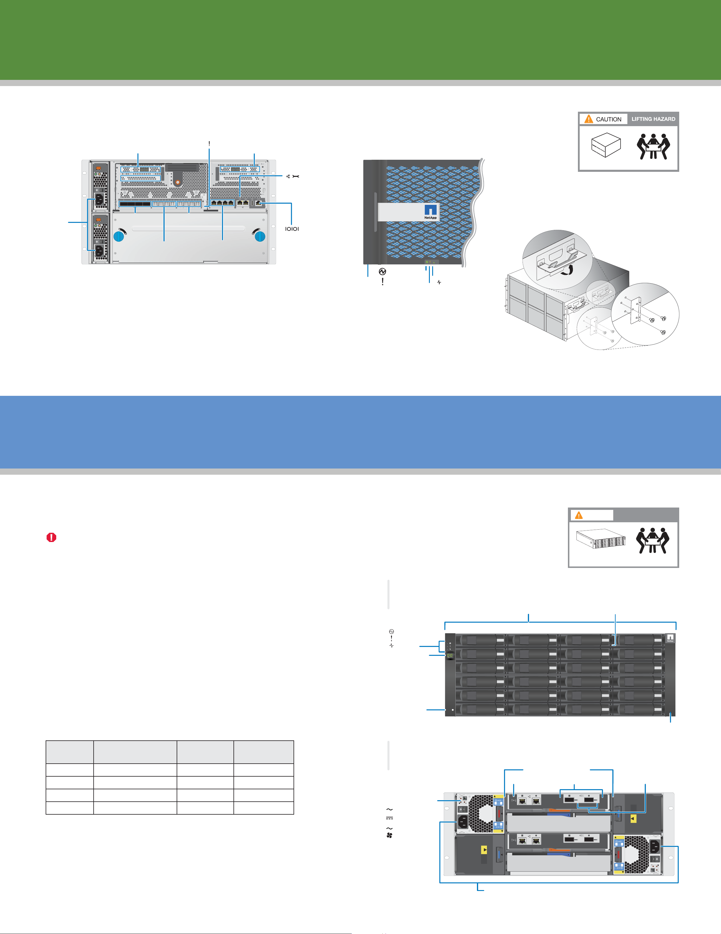
Install controller in rack or cabinet
Controller
attention LED
3
4
RAID card with mini
SAS HD ports (PCI 3)
FRONT VIEW
REAR VIEW
RAID card with mini
SAS HD ports (PCI 1)
1
2
Management port
(wrench icon)
LNKLNKLNKLNKLNKLNKLNKLNKLNKLNKLNKLNK
NV
e0i e0j e0k e0l
Power
supplies
Not
used
e0g 0g e0h 0he0f 0fe0e 0ee0de0ce0be0a0a 0b 0c 0d
Not
used
Console port
10 GigE
ports
1 GigE
ports
(Setting: 9600 N-8-1)
Bezel
Power LED
System
attention LED
NOTE: Controller and disk shelves are shipped in separate boxes.
• Install the mounting rails (provided in rail kit) following the instructions in the rail kit.
A
A
102 lbs. (46.3 kg)
Controller
activity LED
- Use chassis handles while lifting.
• Mount the chassis in the rack.
• Secure chassis to rack using appropriate screws (not provided).
Alternatively, you can mid-mount the chassis using the mid-mount brackets provided in the rail kit.
For detailed rack installation instructions, see SAS Disk Shelves Installation and Service Guide for DS4243, DS2246, DS4486, and DS4246 on the NetApp Support site.
Optional 2-Post
Mid-mount Brackets
Install disk shelves | 3
Install shelf in rack or cabinet
Refer to the the SAS Disk Shelves Installation and Service Guide for DS4243, DS2246, DS4486, and DS4246.
DO NOT remove HDDs from the disk shelf during installation.
Excessive handling of the drives can lead to internal damage.
NOTE: You can install the shelf below the controller.
The distance between the shelf and controller is dependent on the length
of the SAS cables you plan to use.
• Install the mounting rails (provided in rail kit) following
the instructions in rail kit. Be cautious while lifting.
• Mount the disk shelf in the rack.
• Secure the shelf to the rack using the appropriate screws (not provided).
Install disk shelves in the order set at the factory.
A
Front view of disk shelf
Shelf LEDs:
power
shelf fault
activity
Shelf ID digital
display (two digits)
24 Disk drives
4.0TB
4.0TB
4.0TB
CAUTION
3.0TB
3.0TB
3.0TB
3.0TB
3.0TB
3.0TB
LIFTING HAZARD
3.0TB
3.0TB
3.0TB
3.0TB
3.0TB
3.0TB
3.0TB
3.0TB
3.0TB
3.0TB
3.0TB
3.0TB
3.0TB
3.0TB
3.0TB
3.0TB
3.0TB
3.0TB
80-100 lbs. (36-45 kg)
Disk activity and fault LEDs
4.0TB
4.0TB
4.0TB
4.0TB
4.0TB
4.0TB
4.0TB
DS4246
4.0TB
4.0TB
Each shelf is labeled with the associated controller serial number, loop or
stack number of the shelf, and shelf serial number. The loop or stack number
helps to identify the order of installation for each PCI slot on the controller.
The root volume is labeled with loop or stack number 00, and is always the
first shelf attached to the controller. The table shows the relationship of the
controller and shelves for installation:
Controller
PCI Slot
1
1
3
3
Loop or stack number
on shelf label PCI Slot
00
01
10
11
Order of shelf
installation
1
3
2
4
Factory setting
shelf ID
00
01
10
11
It is recommended to verify the shelf IDs prior fully cabling the system.
To verify the IDs, attach a power cable to each shelf, power on the shelf,
note the ID on the front panel, and power o each shelf.
Note: Additional shelves ordered from the factory have the shelf ID set to 00 but
are not installed with the root volume. You must install additional shelves in the
order listed in the table, and reset the shelf ID as described in Section 5.
Left ear cover
B
Rear view of disk shelf
Power supply LEDs :
PSU ok
DC fault
AC
AC fault
Fan fault
4.0TB
4.0TB
4.0TB
4.0TB
4.0TB
4.0TB
Two I/O modules (IOM6)
IOM fault LED
CAUTION
PRUDENCE
1
423
IOM6
423
1
PRUDENCE
CAUTION
ATTENTION
I
BLA
SLO
NSERTPSU
N
TS2 OR 3
KI
N
IOM6
QSFP ports QSFP port link LEDs
LNK LNK
LNK LNK
Two power supplies with integrated fans
IOM6
IOM6
4.0TB
4.0TB
4.0TB
4.0TB
4.0TB
4.0TB
Right ear cover
INSERTPSU
BLANKIN
SLOTS2 OR 3
ION
ATTENT
CAUTION
PRUDENCE
1
423
423
1
PRUDENCE
CAUTION
Page 3
X2067
X3149A
1
3
4
e i
0
e j
0
e k
0
e
i
0
2
c
0
d
0
LNK LNK
0a
e
e0b e0c
e0d
L
NK
LNK
LNK LNK
LNK
LNK
LNK
LNK
0e|0e
e
0f|0f
e
0g|0ge0h|0h
e
Latch release
faces down
on disk shelf
SAS ports
e i
0
e j
0
e k
0
e l
0
1
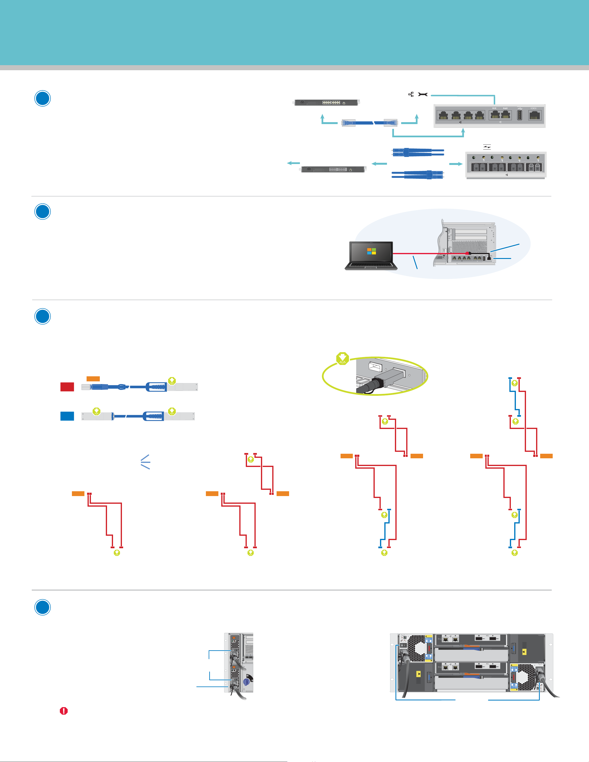
Connect controller to networks
• Connect the management port (wrench icon) on
your controller to the Ethernet switch in your management network, using a network cable.
3
1 3 5 7
1000/100/10M
LNK/
1211141316156587109214
1000/100/10M
LNK/
2 4 6 8
To Ethernet switch
9 11 13 15
10 12 14 16
To management port
(wrench icon) on controller
GigE cable
GigE ports
2
See your network administrator for help connecting
to your switches.
To host
To Ethernet switch 1
• Connect 10GigE ports or GigE ports
for data connection.
Connect controller to computer
The serial console is needed to configure a management IP address
for the AltaVault appliance, using a client. Once this is done, further
configuration can be done using a Web browser and connecting to
the management IP address.
Note that dierent clients may have dierent connection settings.
For example, on a PuTTY connection, set the keyboard to VT100+,
flow control to OFF, and baud rate to 9600.
10GigE ports
1 3 5 7
2 4 6 8
9 11 13 15
10 12 14 16
3
1000/100/10M
LNK/
1211141316156587109214
1000/100/10M
LNK/
10GigE cables
LNK
e0a
LNK
e0b
LNK
e0c
LNK
e0d
AltaVault system
3
Client
4
LNK
0h|0h
e i
e
e i
e k
e j
0
0
0
0
RJ45 serial adapter
Console port
Extension serial cable
to USB connection.
3
Connect controller to shelf
Altavault systems support controller to shelf cables
For optimal system performance, use one of the supported cable configurations displayed below.
• Configure up to three shelves with the AVA400 model
• Configure up to four shelves with the AVA800 model
MINI
1
mini SAS HD-QSFP cable
Cable controller to shelf ports.
2
QSFP-QSFP cable
Cable shelf to shelf ports.
AVA400/AVA800: 2 Shelves
Push all cable ends in
until you hear CLICK.
Shelf 2
ID 10
(with mini SAS/QSFP connectors) and shelf to shelf cables (QSFP/QSFP connectors).
AVA400/AVA800: 3 Shelves
Shelf 2
ID 10
MINI MINI
Controller
AVA800 only: 4 Shelves
Shelf 4
ID 11
Shelf 2
ID 10
MINI MINI
Controller
Controller
4
AVA400/AVA800: 1 Shelf
MINI
Shelf 1
ID 00
Connect power cords
Controller
Shelf 1
ID 00
MINI MINI
Shelf 1
ID 00
Shelf 3
ID 01
Shelf 1
ID 00
Shelf 3
ID 01
•
Controller
Two power supplies MUST be
installed in each controller chassis.
L
L
NK
- Ensure the power switch
on each power supply is in
Power switch
NK
a
0
b
0
the OFF position (O).
- Cable both power supplies
for each controller chassis.
DO NOT power on the controller at this point.
Use
retaining clips
•
Disk shelf
Two power supplies
MUST be installed in
each disk shelf.
- Ensure the power
switch on each power
supplyis in the OFF
position (O).
- Cable both power
supplies for each disk shelf.
CAUTION
PRUDENCE
1
423
IOM6
423
1
PRUDENCE
CAUTION
ATTE
NTIO
N
BL
SL
I
NSE
A
O
NKIN
T
R
S
TPSU
2
O
R
3
IOM6
LNK LNK
LNK LNK
IOM6
R3
SU
O
P
T
R
TS2
ANKIN
SE
LO
N
I
S
BL
N
IO
ATTENT
IOM6
CAUTION
PRUDENCE
1
423
423
1
PRUDENCE
CAUTION
Power switch
For additional configurations, see HELPFUL LINKS.
Page 4
CAUTION
PRUDENCE
CAUTION
PRUDENCE
ATTENT
ION
INSERT PSU
BL
ANK IN
S
LO
TS 2
O
R 3
423
1
423
1
e0be0a
0
e0e e0fe0c e0d
LINKLINKLINK
4.0TB
4.0TB
4.0TB
4.0TB
4.0TB
4.0TB
Complete system setup | 5
1
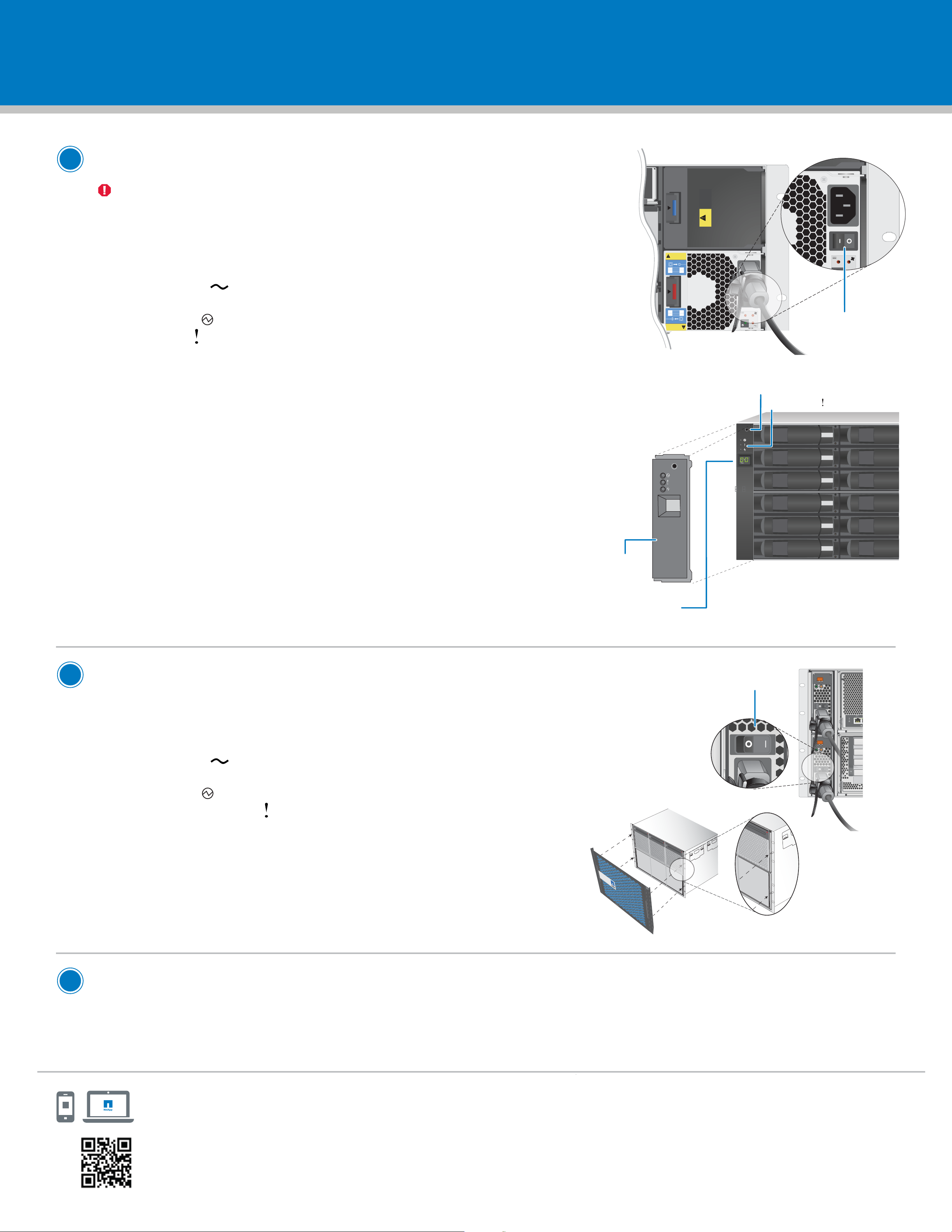
Power on the disk shelf
You must power on all the disk shelves before powering on the controller. Powering on
the controller before the disk shelf prevents AltaVault OS from operating normally.
Power on the disk shelf; move the power switch to the ON ( | ) position.
1.
BOTH power supplies MUST be powered on.
• Verify that the power supplies are working correctly:
PSU OK LED ( ) is lit green in each power supply.
• View the disk shelf LEDs (on shelf front) to verify the disk shelf powered on correctly:
Power LED ( ) is lit green.
Fault LED ( ) is not lit.
2.
Visually verify that the ID for each disk shelf is unique, and if not, set the disk shelf ID.
NOTE: Valid shelf IDs: shelf 1 ID 00; shelf 2 ID 10, shelf 3 ID 01, shelf 4 ID 11.
ID 00 is the default shelf ID.
Power switch
Shelf ID button
Shelf fault LED
a. Using one hand, hold the left ear cover between your thumb and index finger.
Pull either the top or the bottom of the cover until one end is released.
Pull o the left ear cover.
b. Press and hold the shelf ID button until the first digit on the digital display blinks.
c. Press the button until the desired number (between 0 and 9) is displayed.
This number continues to blink.
d. Repeat steps b and c for the second digit.
e. Press and hold the button until the second number stops blinking.
Both numbers on the digital display should blink and the shelf fault
LED illuminates in about five seconds.
The fault LED stays lit until you power-cycle the shelf.
f. Power-cycle the disk shelf to make the new disk shelf ID takes eect.
g. Replace the left ear cover.
4.0TB
4.0TB
4.0TB
4.0TB
4.0TB
4.0TB
Left ear
cover
Digital Display
(two digits)
2
Power on the controller
1.
Power on the controller; move the power switch to the ON (|) position.
BOTH power supplies MUST be powered on.
• Verify that the power supplies are working correctly:
PSU OK LED ( ) is lit green in each power supply.
• View the system LEDs (on controller front) to verify the controller powered on correctly:
Power LED ( ) is lit green.
System attention LED ( ) blinks for a few minutes while AltaVault OS is booting up.
The System attention LED turns o when AltaVault OS is finished booting up.
Install the bezel
2.
• Hold the bezel parallel to the front of the controller.
• Install the bezel on the controller front as shown in the illustration.
Power switch
7
8
9
10
• The bezel will snap into place.
3
Finish the AltaVault setup over the serial console
Open a connection to the serial console port using a terminal program such as PuTTY, and log in using the
default login (admin) and default password (password). You can now complete the AltaVault deployment as described
in the NetApp AltaVault Cloud Integrated Storage Administration Guide.
NetApp
Support Site
HELPFUL LINKS
Visit the NetApp web site for more information.
• AltaVault Resources: https://mysupport.netapp.com/info/web/ECMLP2606636.html
• AltaVault library: http://mysupport.netapp.com/documentation/productlibrary/index.html?productID=62032
• Hardware Universe: https://hwu.netapp.com
• More infomation: http://www.netapp.com
 Loading...