

Page 1
AFF A800 Systems
Installing and setting up the system
You can choose from different content formats to guide you through the installation and setup of your new system.
Note: If needed, before you begin the installation and setup of your new system, you can familiarize yourself with the process
by reviewing the
Installation and setup high-level workflow
.
Installation and setup high-level workflow
Installation and setup PDF poster
Step-by-step instructions with live links to additional content.
Installation and setup PDF poster
Installation and setup videos
Procedure overviews for system cabling and System Manager Guided Setup.
Installation and setup videos
Installation and setup guide
Step-by-step instructions with live links to additional content, animated cabling and searchable content.
Installation and setup guide
on page 2
on page 2
on page 3
on page 3
215-13083_B0 June 2018 Copyright © 2018 NetApp, Inc. All rights reserved.
1
Web: www.netapp.com • Feedback: [email protected]
Page 2
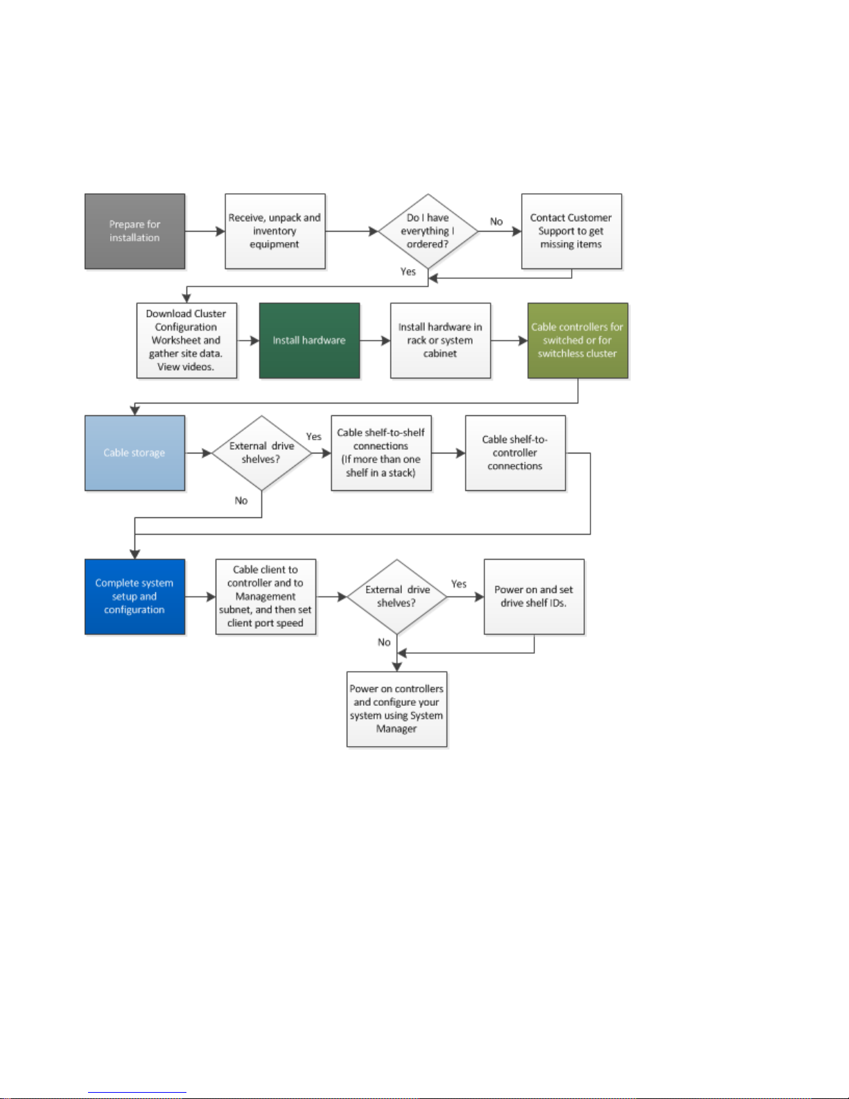
Installation and setup high-level workflow
Before you begin the installation and setup of your new system, you can familiarize yourself with the installation process.
Installation and setup PDF poster
You can use the PDF poster to install and set up your new system. The PDF poster provides step-by-step instructions with live
links to additional content.
Access the
AFF A800 Systems Installation and Setup Instructions
2
Installation and Setup Instructions
PDF poster:
AFF A800 systems: Installing and setting up
Page 3

Installation and setup videos
You can watch these videos for an overview of the installation and setup of your new system.
Video one of two: Hardware installation and cabling
The following video shows how to install and cable your new system.
NetApp video: AFF A800 Systems: Installation and Setup Instructions
Video two of two: Performing end-to-end software configuration
The following video shows end-to-end software configuration for systems running ONTAP 9.2 and later.
NetApp video: Software configuration for vSphere NAS datastores for FAS/AFF systems running ONTAP 9.2
Installation and setup guide
You can use this guide to install and setup your new system. The procedures in this guide provide step-by-step instructions with
live links to additional content, and animated cabling.
Steps
1. Preparing for installation on page 3
2. Installing the hardware on page 5
3. Cabling controllers to your network on page 6
4. Completing system setup and configuration on page 8
Preparing for installation
To install your AFF A800 system, you need to create an account, register the system, and get license keys. You also need to
inventory the appropriate number and type of cables for your system and collect specific network information.
Before you begin
You need to have access to Hardware Universe for information on your site requirements as well as additional information on
your configured system.
NetApp Hardware Universe
You need to provide the following at your site:
• Rack space for the storage system
• Screwdriver
• Additional networking cables to connect your system to your network switch and Microsoft Windows client
• A client with a USB/serial connection and access to a web browser to configure your system
Steps
1. Unpack the contents of all boxes.
2. Record the system serial number from the controller module.
Installation and setup videos
3
Page 4
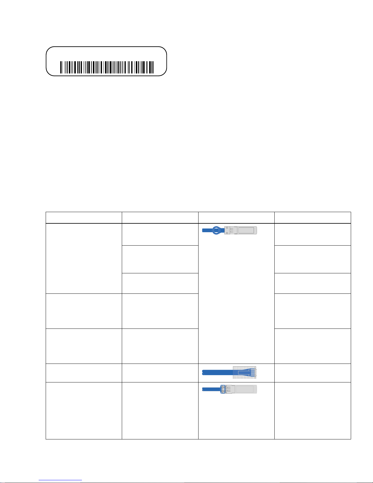
SSN: XXYYYYYYYYYY
3. Set up your account:
a. Login to your existing account or create an account.
NetApp Support Registration
b. Register your system.
NetApp Product Registration
c. Get your license keys.
NetApp Software License Search
Inventory and make a note of the number and types of cables you received.
4.
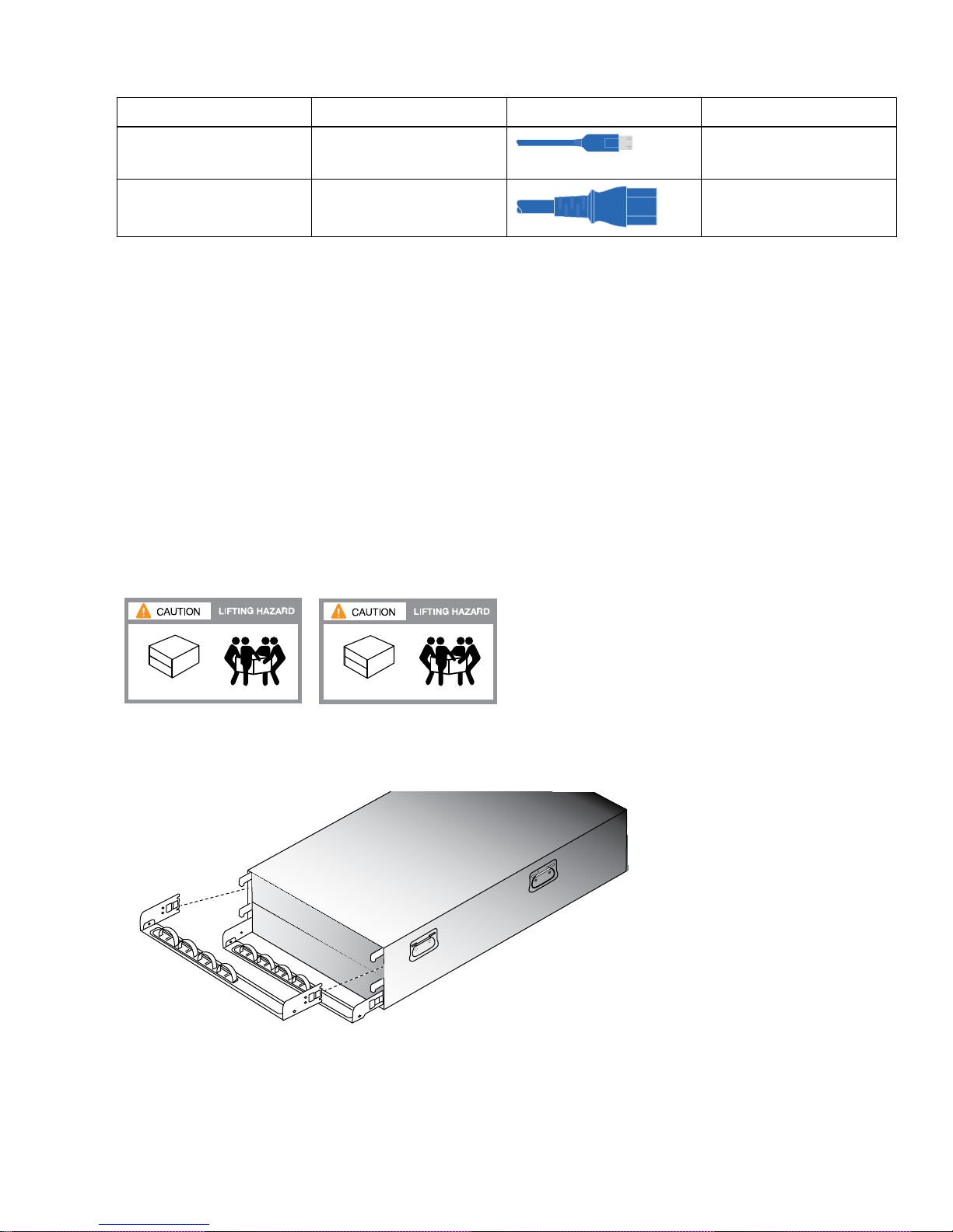
The following table identifies the types of cables you might receive. If you receive a cable not listed in the table, refer to the
Hardware Universe to locate the cable and identify its use.
NetApp Hardware Universe
Type of cable...
100 GbE cable X66211A-05 (112-00595),
10 GbE cable X6566B-3-R6 (112-00300),
25 GbE cable X66240A-2 (112-00598),
RJ-45 (order dependant) Not applicable Management
Fibre Channel X66250-2 (112-00342) 2m;
Part number and length Connector type For...
HA interconnect
0.5m
X66211A-05 (112-00595),
0.5m;
X66211-1 (112-00573), 1m
X66211-2 (112-00574), 2m;
X66211-5 (112-00576), 5m
3m;
X6566B-5-R6 (112-00301),
5m
2m;
X66240A-5 (112-00600),
5m
X66250-5 (112-00344) 5m;
X66250-15 (112-00346)
15m;
X66250-30 (112-00347)
30m
Cluster interconnect
network
Data
Data
4
AFF A800 systems: Installing and setting up
Page 5
Type of cable... Part number and length Connector type For...
24 SSDs
119.2 lbs (54.2 kg)
48 SSDs
132.4 lbs (60.2 kg)
Cable
management
device
Micro-USB console cable Not applicable Console connection during
software setup
Power cables Not applicable Powering up the system
5. Download and complete the
Cluster configuration worksheet
.
Cluster Configuration Worksheet
Installing the hardware
You need to install your system in a 4-post rack or NetApp system cabinet, as applicable.
Steps
Install the rail kits, as needed.
1.
Installing SuperRail into a four-post rack
2. Install and secure your system using the instructions included with the rail kit.
Note: You need to be aware of the safety concerns associated with the weight of the system.
3. Attach cable management devices (as shown).
4. Place the bezel on the front of the system.
Installing the hardware
5
Page 6
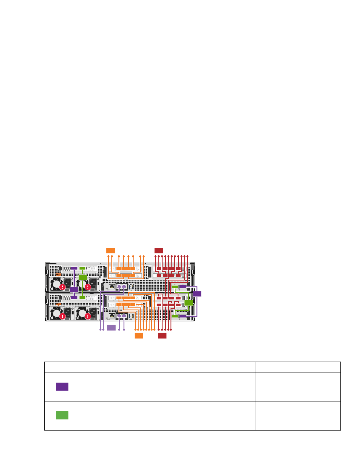
Cabling controllers to your network
X1147A X1147A X1147A X1147A
X1135A
X1135A X1135A
To 10GbE
data network
switches
To management
network switches
1
1
2
2
4
To 10GbE data
network switches
4
3
To fibre channel
switches
To fibre channel
switches
5
5
1
2
You can cable the controllers to your network by using the two-node switchless cluster method or by using the cluster
interconnect network.
Choices
• Cabling a two-node switchless cluster on page 6
• Cabling a 100 GbE cluster interconnect network on page 7
Cabling a two-node switchless cluster
Management network, data network, and FC ports on the controllers are connected to switches. The HA interconnect and cluster
interconnect ports are cabled on both controllers.
Before you begin
See your network administrator for help connecting to the switches.
Steps
1. Cable your system by following the tabulated steps:
Note: Steps 4 and 5 are optional and configuration dependent.
Note: As you insert the connector, you should feel it click into place; if you do not feel it click, remove it, turn it around
and try again.
Step
Perform on each controller Ports used
Cable the HA interconnect ports.
Cable the cluster interconnect ports.
• e0b to e0b
• e1b to e1b
• e0a to e0a
• e1a to e1a
6
AFF A800 systems: Installing and setting up
Page 7
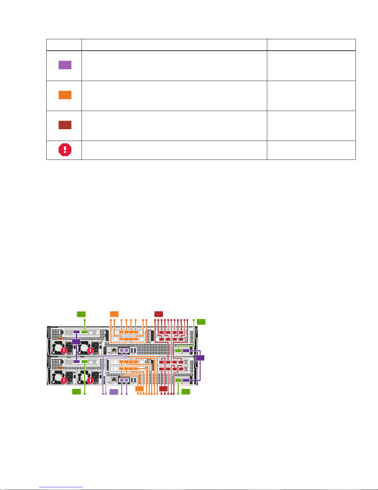
Step Perform on each controller Ports used
3
4
5
X1147A X1147A X1147A X1147A
X1135A
X1135A X1135A
To 10GbE
data network
switches
To management
network switches
To cluster
interconnect
switches
1
1
2
2
To cluster
interconnect
switches
2
To cluster
interconnect
switches
2
4
To 10GbE data
network switches
4
3
To fibre
channel
switches
To fibre
channel
switches
5
To cluster
interconnect
switches
5
• e0M
Cable the management ports to the management network switches.
• BMC
• e2a through e2d
Cable the data ports to the data network switches.
• e3a through e3d
• 4a through 4d
Cable the Fibre Channel ports to the FC switches.
• 5a through 5d
DO NOT plug the power cords in at this point. Not applicable.
To complete setting up your system, see
2.
Completing system setup and configuration
on page 8
Cabling a 100 GbE cluster interconnect network
Cluster interconnect, management network, data, and Fibre Channel ports on the controllers are connected to switches while the
HA interconnect ports are cabled on both controllers.
Before you begin
See your network administrator for help connecting to the switches.
Steps
1. Cable your system by following the tabulated steps:
Note: Steps 4 and 5 are optional and configuration dependent.
Note: As you insert the connector, you should feel it click into place; if you do not feel it click, remove it, turn it around
and try again.
Cabling controllers to your network
7
Page 8
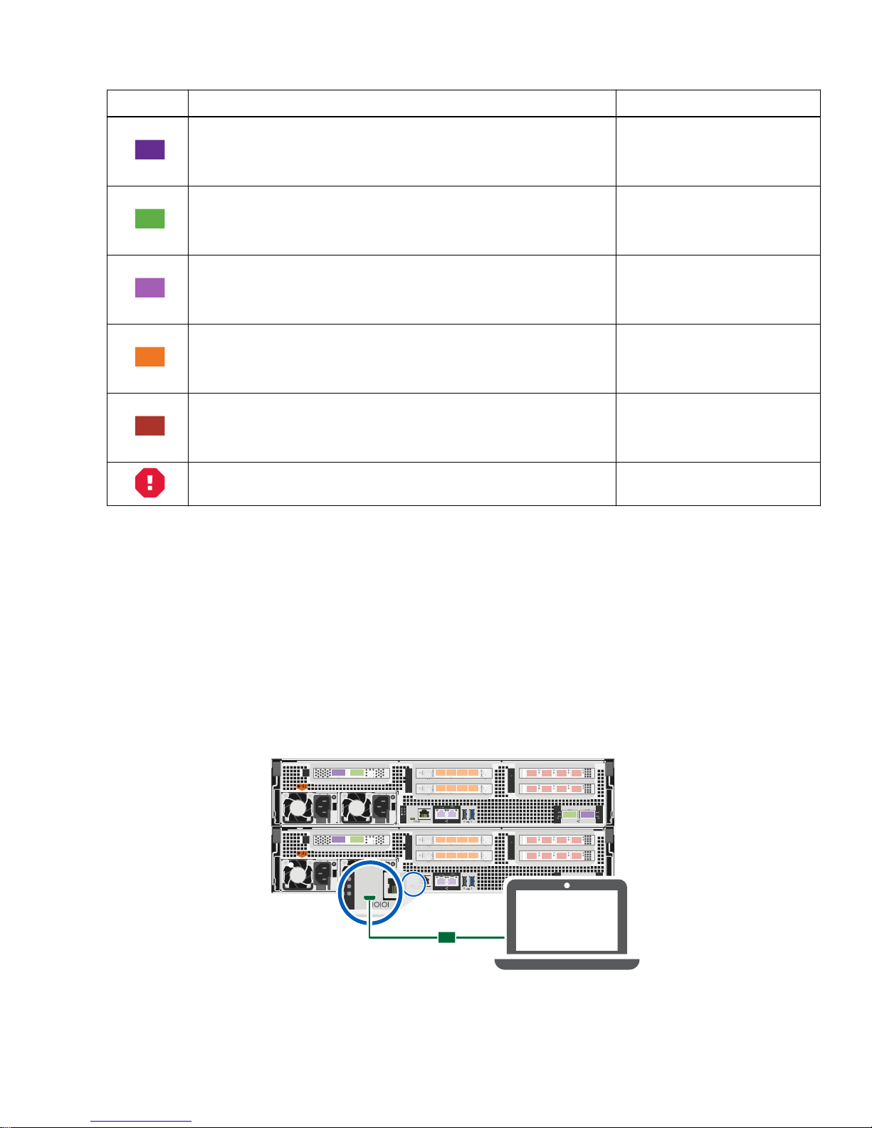
Step Perform on each controller Ports used
1
2
3
4
5
X1147A X1147A X1147A X1147A
X1135A
X1135A X1135A
X1135A
X1135AX1135A X1135A
X1147A X1147A X1147AX1147A
Client
1
• e0b to e0b
Cable the HA interconnect ports
• e1b to e1b
Cable the cluster interconnect ports to the 100 GbE cluster interconnect
switches.
• e0a
• e1a
• e0M
Cable the management ports to the management network switches
• BMC
• e2a through e2d
Cable the data ports to the data network switches
• e3a through e3d
• 4a through 4d
Cable the Fibre Channel ports to the FC switches
• 5a through 5d
DO NOT plug the power cords in at this point. Not applicable.
2. To complete setting up your system, see
Completing system setup and configuration
on page 8
Completing system setup and configuration
You must cable and configure your Windows client before you complete your AFF A800 system setup and configuration.
Steps
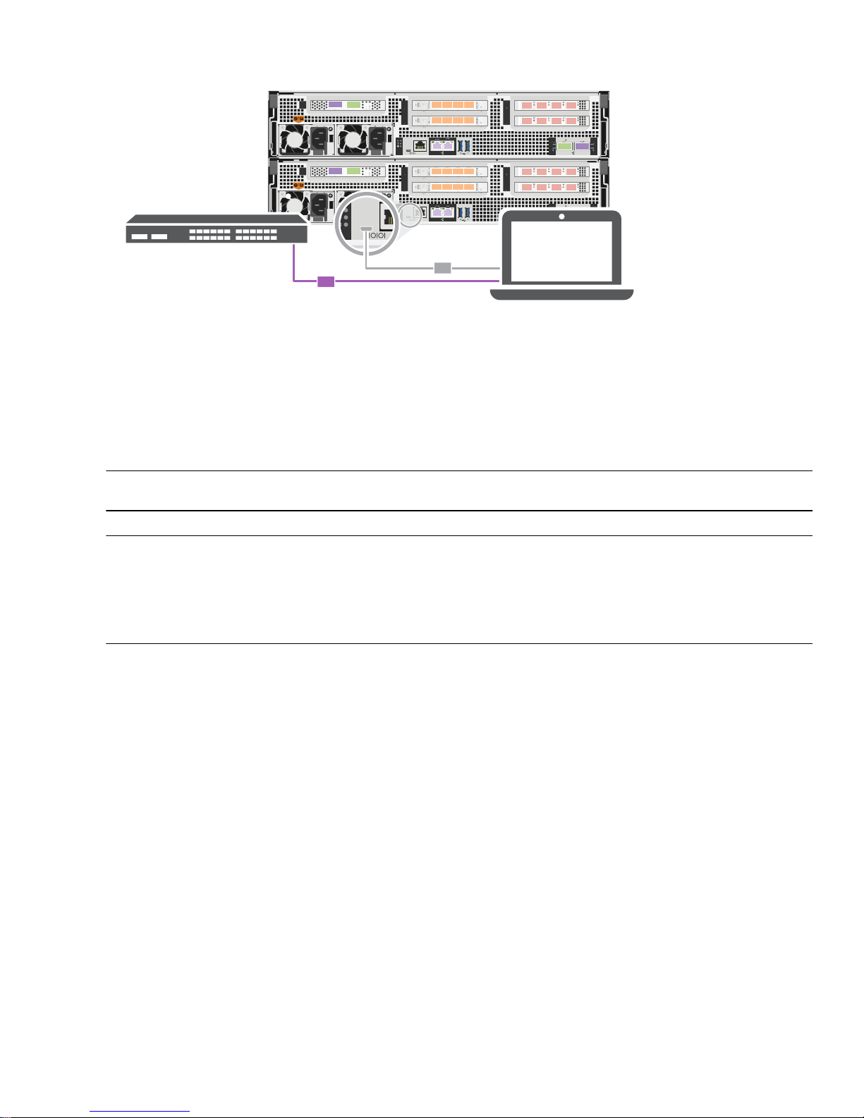
1. Cable and configure your client:
a. Connect the console cable to the client and the console port on the controller module using the console cable that came
with your system.
b. Connect the client to the switch on the management subnet.
8
AFF A800 systems: Installing and setting up
Page 9
X1147A X1147A X1147A X1147A
X1135A
X1135A X1135A
X1135A
X1135AX1135A X1135A
X1147A X1147A X1147AX1147A
Management
subnet
Client
2
1
c. Assign a TCP/IP address to the client, using one that is on the management subnet.
d. Set the console port on the client to 115,200 baud with N-8-1.
Note: See your client's online help for how to configure the console port.
Plug the power cords into the power supplies, and then connect them to power sources on different circuits.
2.
3. Assign an initial node management IP address to one of the nodes.
If the management network has
Then...
DHCP...
Configured Record the IP address assigned to the new controller modules.
Not configured
a. Open a console session using PuTTY, a terminal server, or the equivalent for your
environment.
Note: Check your client's online help if you do not know how to configure PuTTY.
b. Enter the management IP address when prompted by the script.
4. Using System Manager on your client, configure your cluster:
a. Point your browser to the node management IP address (from Step 3).
Note: The format for the address is https://x.x.x.x.
b. Configure the system using the data you collected in the
Cluster Configuration Worksheet
Copyright information
Copyright © 2018 NetApp, Inc. All rights reserved. Printed in the U.S.
Cluster configuration worksheet
.
No part of this document covered by copyright may be reproduced in any form or by any means—graphic, electronic, or
mechanical, including photocopying, recording, taping, or storage in an electronic retrieval system—without prior written
permission of the copyright owner.
Software derived from copyrighted NetApp material is subject to the following license and disclaimer:
THIS SOFTWARE IS PROVIDED BY NETAPP "AS IS" AND WITHOUT ANY EXPRESS OR IMPLIED WARRANTIES,
INCLUDING, BUT NOT LIMITED TO, THE IMPLIED WARRANTIES OF MERCHANTABILITY AND FITNESS FOR A
PARTICULAR PURPOSE, WHICH ARE HEREBY DISCLAIMED. IN NO EVENT SHALL NETAPP BE LIABLE FOR
ANY DIRECT, INDIRECT, INCIDENTAL, SPECIAL, EXEMPLARY, OR CONSEQUENTIAL DAMAGES (INCLUDING,
Copyright information
9
Page 10

BUT NOT LIMITED TO, PROCUREMENT OF SUBSTITUTE GOODS OR SERVICES; LOSS OF USE, DATA, OR
PROFITS; OR BUSINESS INTERRUPTION) HOWEVER CAUSED AND ON ANY THEORY OF LIABILITY, WHETHER
IN CONTRACT, STRICT LIABILITY, OR TORT (INCLUDING NEGLIGENCE OR OTHERWISE) ARISING IN ANY WAY
OUT OF THE USE OF THIS SOFTWARE, EVEN IF ADVISED OF THE POSSIBILITY OF SUCH DAMAGE.
NetApp reserves the right to change any products described herein at any time, and without notice. NetApp assumes no
responsibility or liability arising from the use of products described herein, except as expressly agreed to in writing by NetApp.
The use or purchase of this product does not convey a license under any patent rights, trademark rights, or any other intellectual
property rights of NetApp.
The product described in this manual may be protected by one or more U.S. patents, foreign patents, or pending applications.
RESTRICTED RIGHTS LEGEND: Use, duplication, or disclosure by the government is subject to restrictions as set forth in
subparagraph (c)(1)(ii) of the Rights in Technical Data and Computer Software clause at DFARS 252.277-7103 (October 1988)
and FAR 52-227-19 (June 1987).
Trademark information
NETAPP, the NETAPP logo, and the marks listed on the NetApp Trademarks page are trademarks of NetApp, Inc. Other
company and product names may be trademarks of their respective owners.
http://www.netapp.com/us/legal/netapptmlist.aspx
How to send comments about documentation and receive
update notifications
You can help us to improve the quality of our documentation by sending us your feedback. You can receive automatic
notification when production-level (GA/FCS) documentation is initially released or important changes are made to existing
production-level documents.
If you have suggestions for improving this document, send us your comments by email.
To help us direct your comments to the correct division, include in the subject line the product name, version, and operating
system.
If you want to be notified automatically when production-level documentation is released or important changes are made to
existing production-level documents, follow Twitter account @NetAppDoc.
You can also contact us in the following ways:
• NetApp, Inc., 495 East Java Drive, Sunnyvale, CA 94089 U.S.
• Telephone: +1 (408) 822-6000
• Fax: +1 (408) 822-4501
• Support telephone: +1 (888) 463-8277
10
AFF A800 systems: Installing and setting up
 Loading...