

Page 1
Prepare for installation Install hardware Cable storage
AFF A700 and
FAS9000 Systems
Installation and Setup Instructions
Complete system setup
and configuration
1 2 3 4
Prepare for installation | 1
1. Go to mysupport.netapp.com and create an account, register your system, and get your license keys.
Pre-setup
2. Unpack all boxes and inventory contents.
3. Go to the AFF and FAS System Documentation Center and click AFF A700 and FAS9000 systems, and then Installation and Setup:
- Download Config Advisor.
- Download and complete the Cluster Configuration Worksheet.
- Watch the videos listed under Setup videos.
Storage cables
Controller-to-controller cablesHost cables
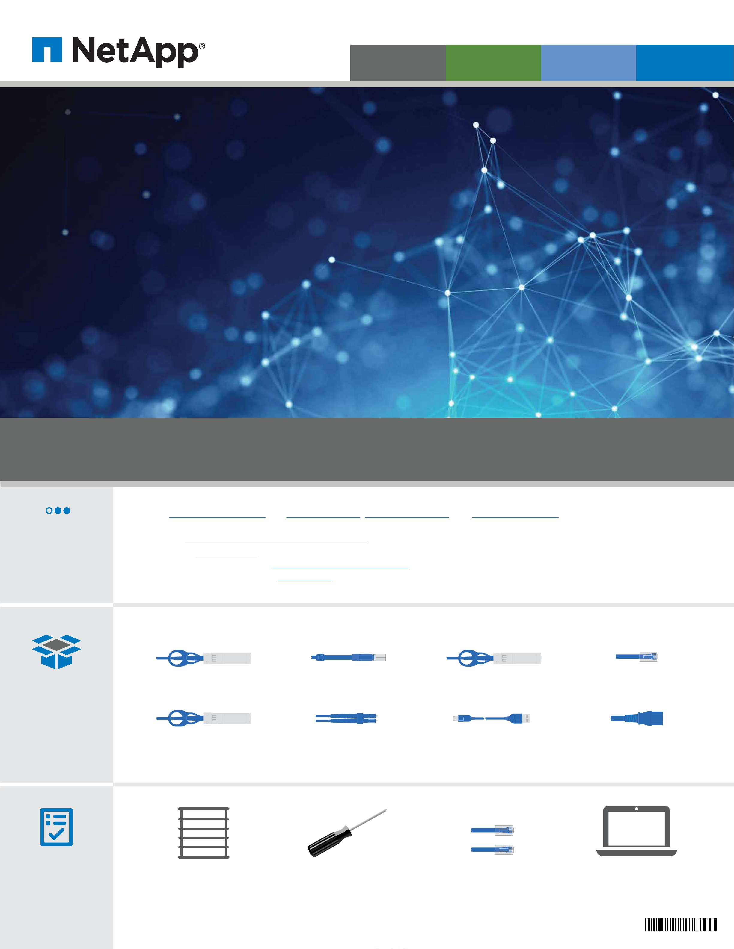
In the box
10 GbE network cable
Part number 112-00299,
112-00300, or 112-00301
40 GbE network cable
Part number 112-00543
MiniSAS HD cable
Part number 112-00436,
112-00437, or 112-00438
Optical network cable
Part number 112-00188,
112-00189, or 112-00090
40 GbE cluster interconnect cable
Part number 112-00542 or 112-00543
Part number 112-00508
Ethernet cables
Power cablesUSB console cable
You provide
Rack space
8U per chassis
Screwdriver
Phillips #2
Additional network cables
For connecting your storage
to your network switch and client
Client
Runs the software to configure
your storage system
210-06635+B0
Page 2
Install hardware | 2 Cable storage | 3
1
2
AC AC
1
2
AC AC
1
2
AC AC
1
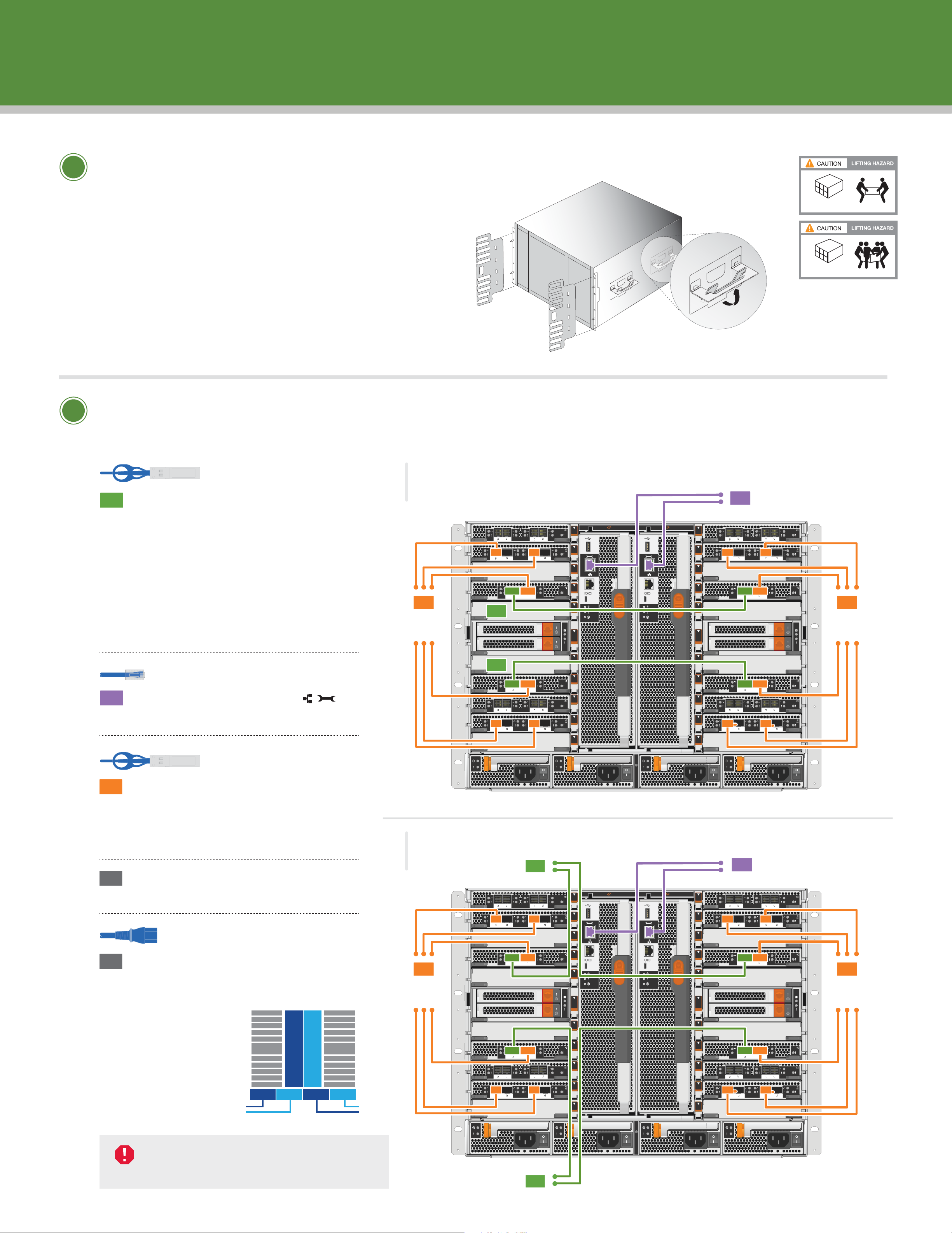
Unpack and install the system.
• Unpack all boxes and inventory contents.
• Install rail kits, as needed, using the rail kit
installation instructions.
• Install the empty chassis into the system cabinet or rack.
• Reinstall the system components into the chassis,
matching the chassis slot ID with the slot ID
sticker on the component.
• Attach cable management device.
• Place the bezel on the front of the system.
Handles and cable
management device
90 lbs. (41 kg)
Empty chassis
240 lbs. (109 kg)
Fully-populated chassis
2
Cable controller to switches
(choose option A or B below)
See your network administrator for help connecting to your switch.
Cluster interconnect cable
Part number 112-00542 or 112-00543
1
OPTION A:
A
Two node switchless cluster, ONTAP
Cable cluster interconnect ports A
together in slot A4 and B4 (e4a) and
again in slot A8 and B8 (e8a).
OPTION B:
Connect ports a in slot A4, B4, A8
and B8 (e4a, e8a) to the cluster
switch. Use the cables supported by
your switch.
Ethernet cable
3
To data
network
switches
Controller A
1
1
To management
2
network switches
Controller B
A1
A2
A3
A4
A5
6-1
A6
6-2
A7
A8
B1
B2
B3
B4
B5
6-1
B6
6-2
B7
B8
3
To data
network
switches
2
3
4
Connect the wrench ports
to the management switches.
10 GbE network cable
(
PN 112-00299, 112-00300 or 112-00301)
Connect the e4b and e8b ports
to the data switches.
Connect the e2a, e2c, e10a and
e10c ports to the data switches.
Strap the cables to the cable
management arms (not shown).
B
A9
A10
A11
PSU 1
PSU 2 PSU 3 PSU 4
Switched HA configuration
To cluster switches
Controller A
1
A1
A2
B9
B10
B11
To management
2
network switches
Controller B
B1
B2
Power cable
5
Connect the power cables to the
PSUs and connect them to dierent
power sources (not shown).
PSU 1 and PSU 3
provide power to
all side A FRUs,
A
B
PSU 2 and PSU 4
provide power to
all side B FRUs.
PSU 1 PSU 2 PSU 3 PSU 4
1st
power
source
DO NOT power on controllers
at this point.
2nd
power
source
3
To data
network
switches
PSU 1
To cluster switches
A3
A4
A5
6-1
A6
6-2
A7
A8
A9
A10
A11
PSU 2 PSU 3 PSU 4
B3
B4
B5
6-1
B6
6-2
B7
B8
B9
B10
B11
3
To data
network
switches
1
Page 3
Cabling a FAS9000 or an AFF A700 WITH external storage
1
2
AC AC
1
2
AC AC
1
2
AC AC
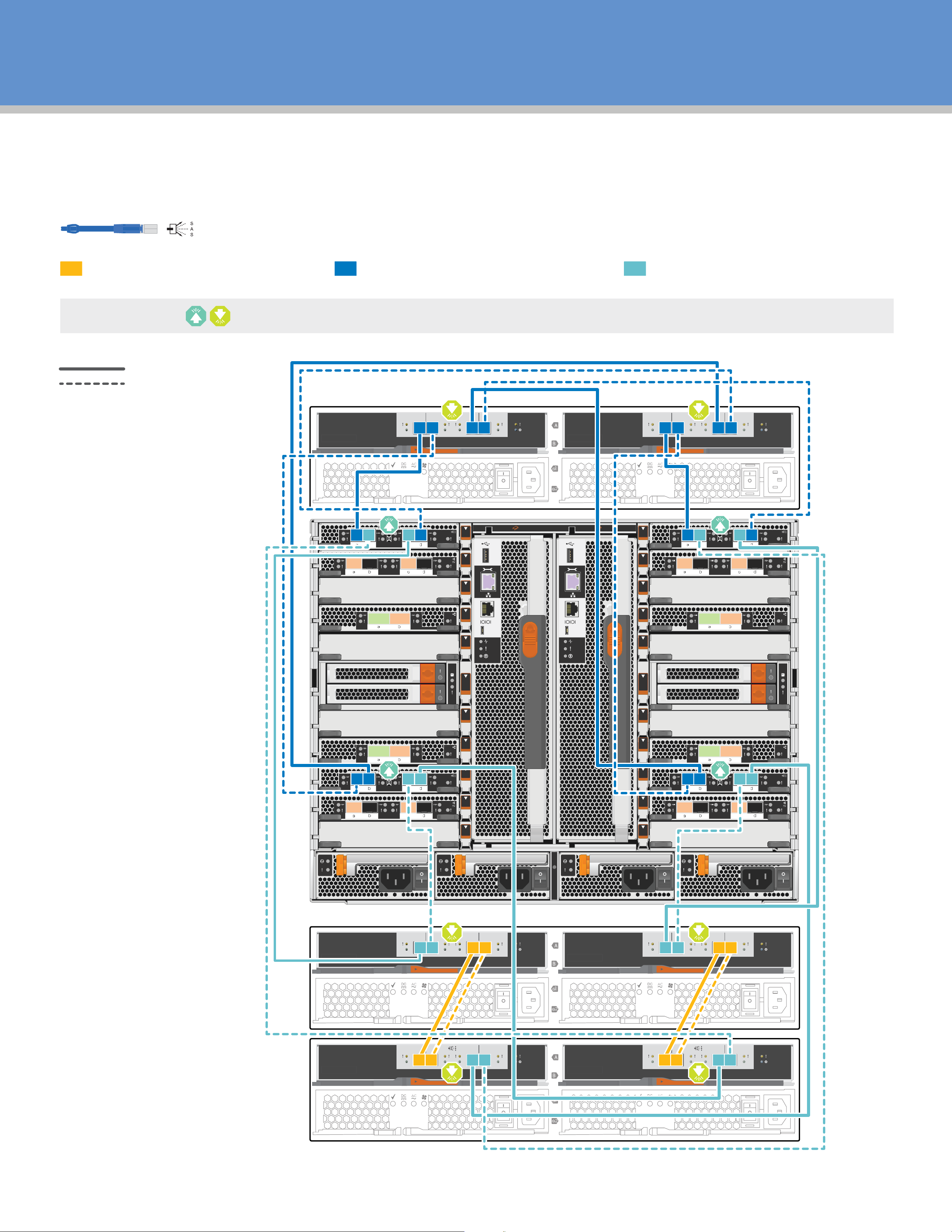
(DS212C or DS224C disk shelves)
Mini-SAS HD cable
(PN 112-00436, 112-00437, or 112-00438)
Connect the shelf-to-shelf ports Connect the controllers to Stack 1 Connect the controllers to Stack 2
321
Insert SAS cable tab UP or tab DOWN and gently push into place until it clicks.
Multipath HA cabling
Quad-path HA cabling
(optional)
Stack 1
IOMA IOMB
IOM12
21
LN K LN K43LN K LN K
IOM12
LN K LN K43LN K LN K
21
A1
A2
A3
A4
A5
6-1
Controller 1 Controller 2
A6
6-2
A7
A8
B1
B2
B3
B4
B5
6-1
B6
6-2
B7
B8
Stack 2
First shelf
A9
A10
A11
B9
B10
B11
IOMA IOMB
IOM12
21
LN K LN K43LN K LN K
IOM12
LN K LN K43LN K LN K
21
IOM12
Last shelf
21
LN K LN K43LN K LN K
IOM12
21
LN K LN K43LN K LN K
Page 4
Complete system setup and configuration | 4
A5
A4
A3
A2
A1
B5
B4
B3
B2
B1
A5
A6
A4
A3
A2
A1
A10
A9
A8
A7
A11
B5
B6
B4
B3
B2
B1
B10
B9
B8
B7
B11
6-2
6-1
6-2
6-1
A
B
1
2
1
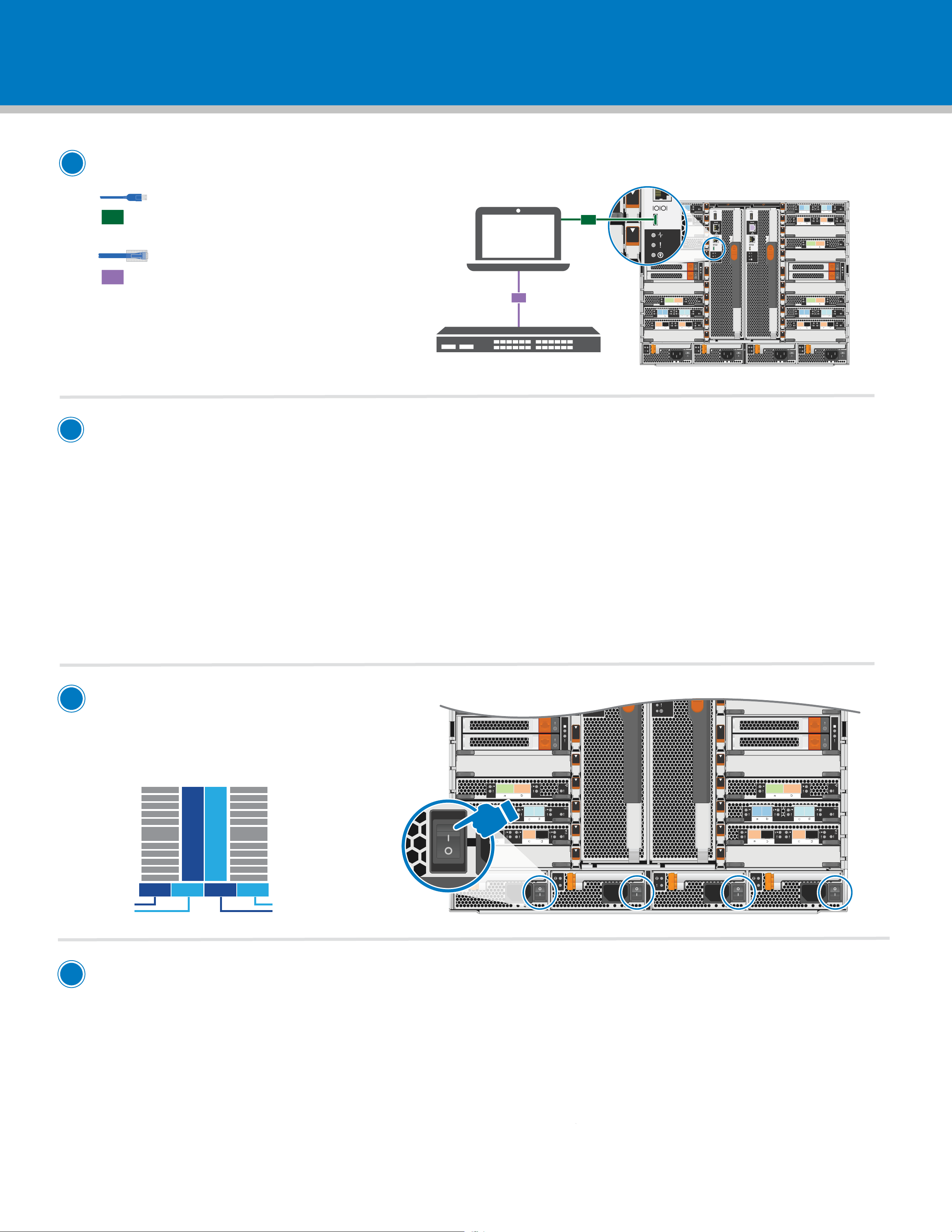
Cable and configure your client
micro USB console cable
Connect the console cable to the client
1
and the console port on the controller module.
Ethernet cable
2
Connect the client to the switch
on the management subnet:
a. Give the client a TCP/IP address
on the management subnet.
b. Set the console port on the client
to 115,200 baud with N-8-1 and flow
control disabled.
Client
2
Management subnet
AFF A700/FAS9000 system
A1
1
A2
A3
A4
A5
6-1
A6
6-2
A7
A8
A9
A10
A11
B1
B2
B3
B4
B5
6-1
B6
B7
B8
B9
B10
B11
6-2
2
If your system has one or more external drive shelves,
set the shelf IDs:
1. Power on the drive shelf, and then remove the end cap on the left of the shelf.
2. Press and hold the orange button until the first digit blinks, and then press the button to advance
the first digit (0-9) to the desired number. The first digit continues to blink.
3. Press and hold the button until the second digit blinks, and then press the button to advance
the second digit (0-9) to the desired number. The first digit stops blinking, and the second digit continues to blink.
4. Press and hold the button until the second digit stops blinking, and then replace the end cap on the shelf.
5. Wait about 10 seconds for both digits to start blinking again and for the LED to illuminate,
and then power-cycle the drive shelf to make the shelf ID take eect.
6. Repeat these steps for any remaining drive shelves.
3
Turn on the power switches
to all nodes
PSU 1 and PSU 3 provide power to all side A FRUs,
PSU 2 and PSU 4 provide power to all side B FRUs.
1st
power
source
A
PSU 1 PSU 2 PSU 3 PSU 4
B
2nd
power
source
4
Configure your system using the Application Setup Wizard
1. Assign an initial node management IP address to one of the nodes.
If you have DHCP configured on your management network, record the IP address assigned to the new controllers.
Otherwise,
a. Open a console session using PuTTY, a terminal server, or the equivalent for your environment.
b. Enter the node management IP address when prompted.
2. Use System Manager Guided Setup to configure your cluster.
a. Point your browser to the address you assigned in step 1: https://x.x.x.x.
b. Enter the data from your Cluster Configuration Worksheet.
3. Run Config Advisor from your client to check the hardware installation of your system and for conformance
to NetApp® recommended settings.
 Loading...