

Page 1
TMTM
NetMeter for
Patent Pending
DeviceNet
Users Guide
P/N 715-0016 V1.2
Page 2
Essentials
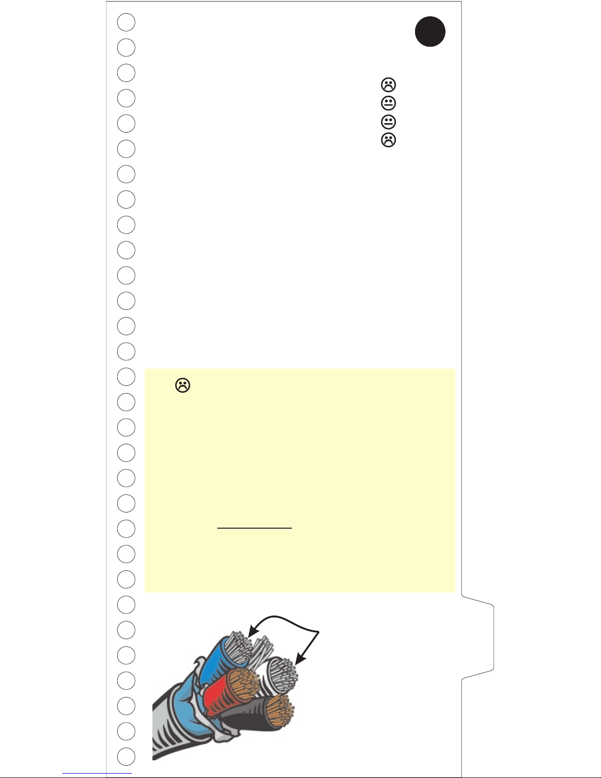
DeviceNet Cable Essentials
AutoSearch Mode
Read this first!
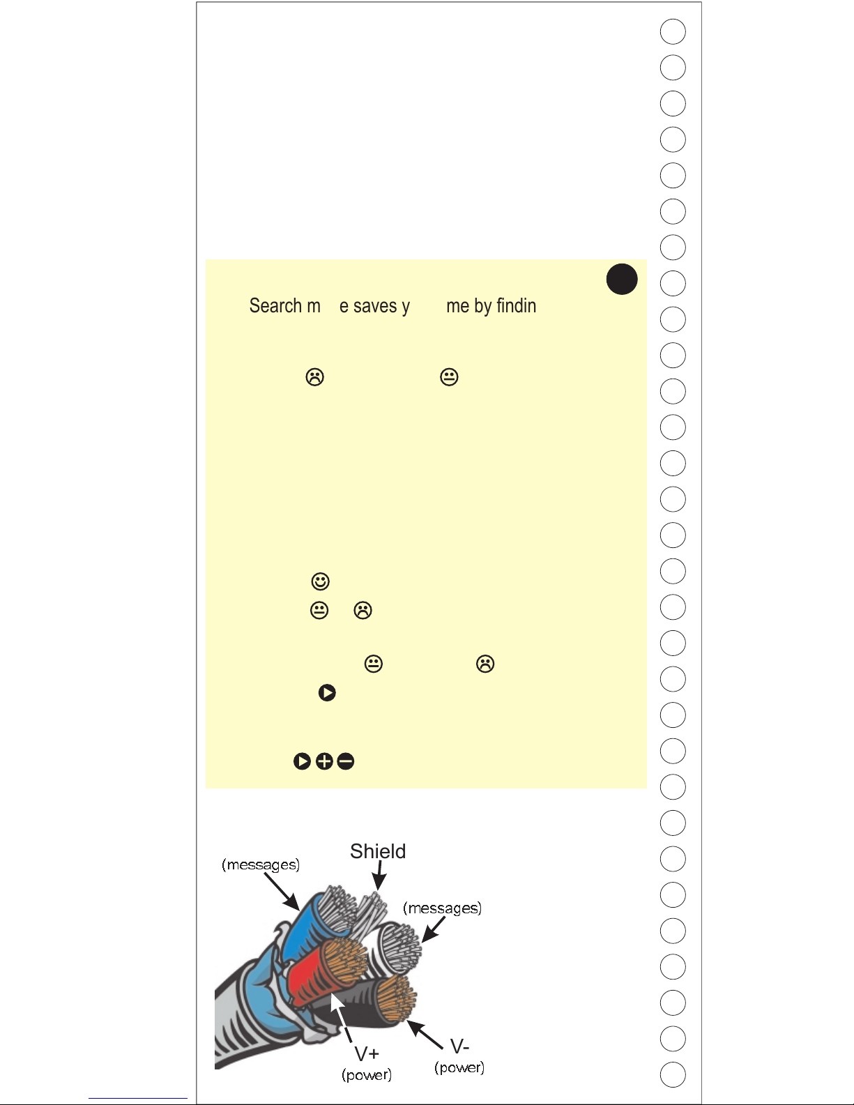
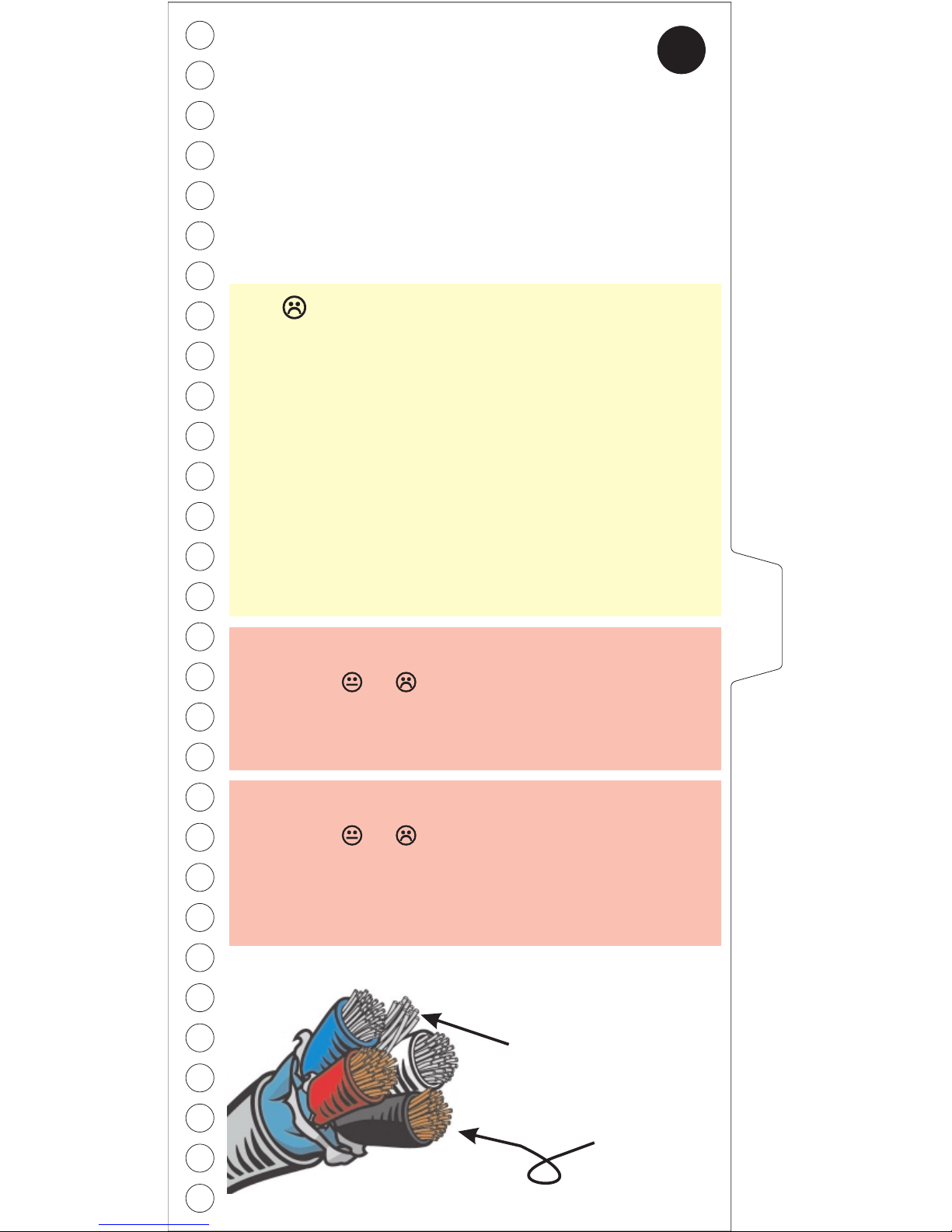
DeviceNet cable
has five wires
inside. Each has a
specific purpose
which is referenced
in this manual.
CANL
(messages)
Shield
V-
(power)
V+
(power)
CANH
(messages)
AutoSearch mode saves you time by finding the network
measurements that exceed acceptable limits. It works by
examining all measurements and then pinpointing any
that exceed or are close to specified limits. For
each problem measurement NetMeter indicates the
measurement's switch position number in the upper left
corner of the display. Rotate the selector switch to the
indicated setting to view related measurements.
NetMeter requires 2 ‘AA’ Alkaline batteries for viewing
measurements offline. NetMeter must be plugged into a
powered network to get most measurements. NetMeter
will run off DeviceNet network power, even without
batteries installed. Remember to install batteries if you
plan to use the Lock and offline viewing features.
How to Use AutoSearch ...
1. Make sure the Lock switch is in the “Run” position and
turn the selector switch to AutoSearch
2. If you see - all measurements are within limits.
3. If you see or then read the display like this ...
“Switch setting <Setting #>, <MIN> or <MAX> and/or
<P-P> is close to or Exceeds the spec limits.”
Then press and repeat the process for the next
bad/marginal value.To get more detail, turn the
selector switch to the indicated position and use the
buttons to access related measurements.
2
1
Page 3
How to use this manual
This is a reference manual for the DeviceNet NetMeter
(DN-MTR). For each NetMeter switch position you will
find a page explaining the measurements available, and
suggested actions and/or remedies if your network is not
healthy.
On each page you’ll find:
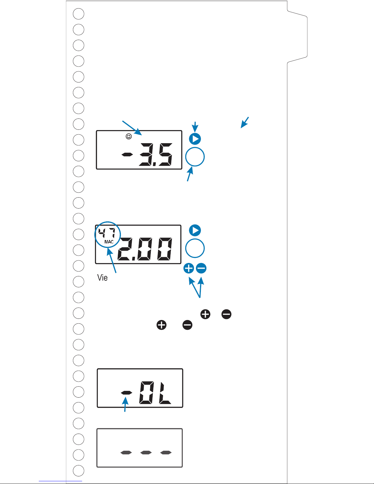
The minimum shield
voltage recorded
since the NetMeter
was plugged in or
reset is -3.5V.
x
1
V
250
MIN
x
5
Displays the
maximum frame rate
per second on the
network since the
NetMeter was
plugged in or reset.
LCD display
# of times to push the advance button after moving
the selector switch to display this measurement.
Description
Push the Advance
button
You can view this measurement for each active
device by pressing the or buttons.
Pressing and at the same time displays
the overall network measurement again.
The measured value
exceeds the positive or
negative input range.
No measurement taken
(see additional details for
specific measurements).
Special Conditions:
Sign indicates negative over-range
/S
250
MAX
K
AUTOSEARCH
3
MAC
Viewing measurement
for this device (MAC ID)
Page 4
Using the NetMeter
To lock measurements for offline viewing move the lock
switch to the position. To erase
Stored values are retained indefinitely, providing the lock
switch is left in the position, and the
- even if the meter is turned off.
batteries are
good
stored values and
restart bus analysis move the lock switch to “Run”.
The NetMeter is reset (Min/Max and other stored
measurements cleared) when the Lock switch is moved
to the "Run" position, and when the power switch is
turned On while the Lock switch is in the "Run" position.
You may reset stored measurements by either turning
the meter off and on again, or by moving the Lock switch
to and back to “Run”.
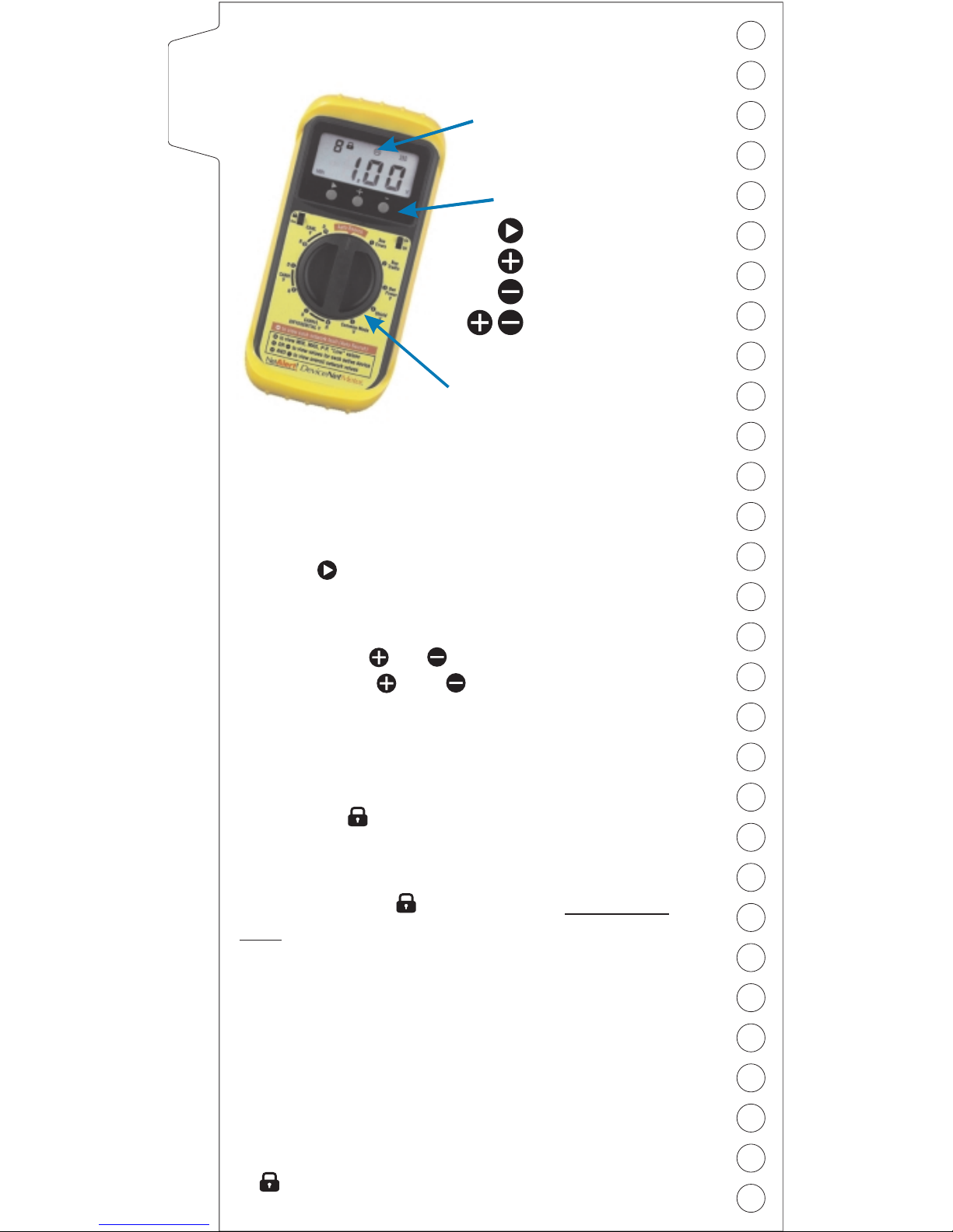
Each selector switch position accesses a different bus
measurement, and each supports several different
measurement types.
Pressing cycles the display through the different
measurements available at each switch position.
Some measurements allow a detailed view for each
MAC ID. Press OR to cycle through the active
MAC IDs. Press AND together to return to the
overall network view
Display Lock
Resetting Min/Max Measurements
Viewing Measurements
LCD Display
Pushbuttons
Selector switch
Next measurement
Next MACID
Previous MACID
Return to Network
View (push at the
same time)
4
Page 5
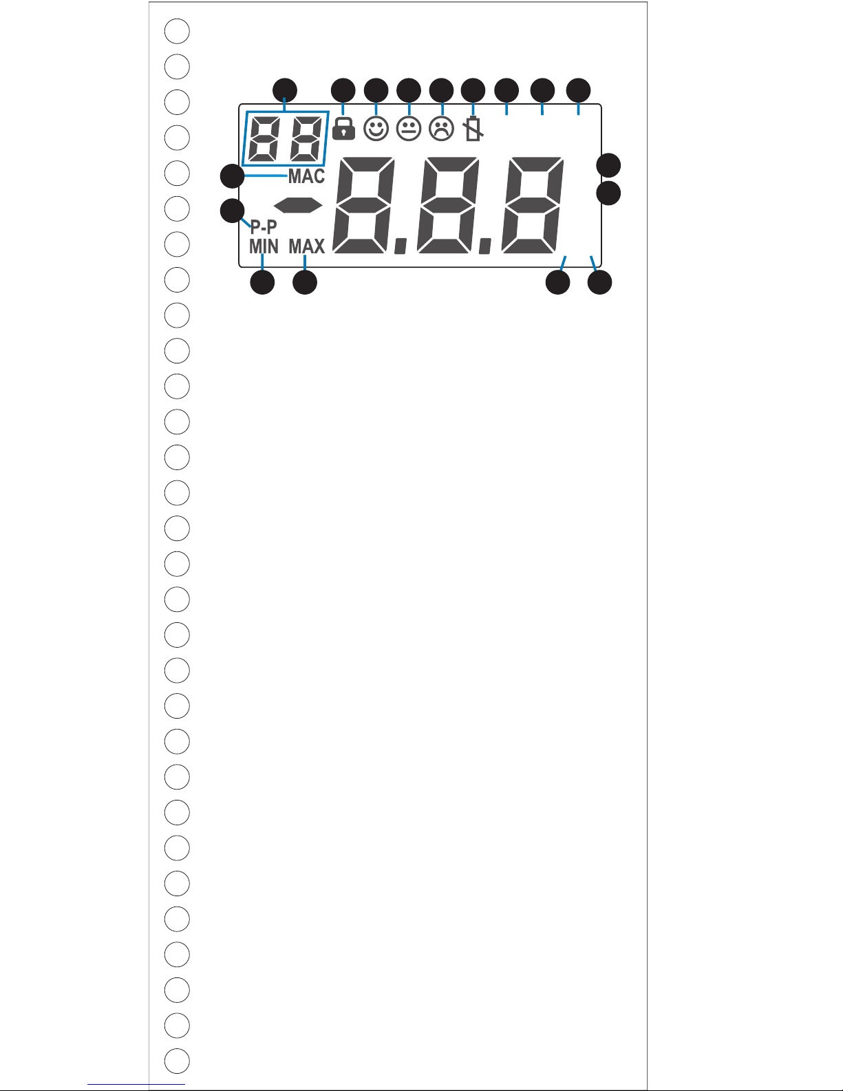
KV
/S
%
125 250 500
1 2 3 4 5 6 7 8 9
10
11
121315 14
16
17
1
Network MAC ID (node #) or NetMeter switch
setting number (AutoSearch)
2
Display locked indicator (“lock” switch is on)
3
Measurement displayed is acceptable
4
Measurement displayed is marginal
5
Measurement displayed is unacceptable
6
Battery low - stored measurements may be lost
7
125 Kbaud network activity detected
8
250 Kbaud network activity detected
9
500 Kbaud network activity detected
10
Measurement unit is % bandwidth
11
Measurement unit is errors / messages per second
12
Measurement unit is volts
13
Measurement displayed is in thousands (kilo)
14
Measurement displayed is a maximum value
15
Measurement displayed is a minimum value
17
Displayed when viewing measurements for a
particular MAC ID. Not displayed in AutoSearch
mode when the value shown in the top left corner is
a switch position.
16
valuepeak-to-peakaisdisplayedMeasurement
*
If none of MIN, MAX or P-P are shown then the
value displayed is a “live” measurement, or the most
recent “Live” measurement if the “lock” switch is on.
Display
5
Page 6
Bus Errors
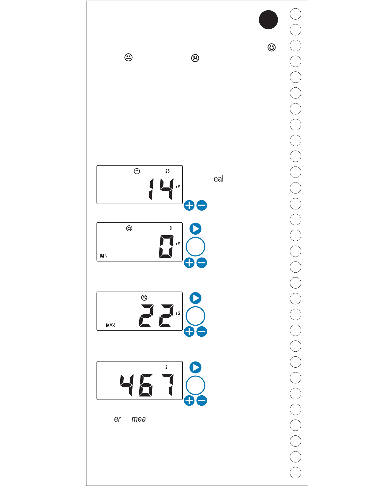
NetMeter tracks network data transmission errors in realtime, and lets you know if the error rate is acceptable ,
marginal , or unacceptable . Any error rate greater
than zero is undesirable (although your network may still
function since CAN automatically retransmits after
errors). An error rate greater than 10/s indicates a
problem that should be investigated.
NetMeter uses unique technology to accurately
determine which node was attempting to transmit when a
bus error occurs
Display
What it means
/S
250
/S
250
MIN
250
Real-time error rate
of 14 errors/second
Incremental error
count on the entire
network since the
NetMeter was
connected or reset.
Maximum bus error
rate on the whole
network since
NetMeter was
connected or reset.
Minimum bus error
rate on whole
network since
NetMeter was
connected to the
network or reset.
2
6
x
1
x
2
x
3
/S
250
MAX
Node error measurements only include errors known to
have occurred when the node is transmitting. Frames
with corrupt ID fields, and frames that cannot be
attributed to specific nodes are not included in node
measurements. It is common for the sum of per-node
results to be less than the overall network values.
Page 7
A node set to the wrong baudrate causes bus errors
(affecting other nodes) when it attempts to go online.
Bus Errors
What do to when you see or :
!
If you suspect an intermittent cable or
connector, shake, bend or twist the suspected
cable and/or connector while watching the error
rate for changes (up or down).
!
Check the other measurements and investigate
the suspect device(s) for faults consistent with
the observed symptoms.
Some techniques you can use are:
!
Press or to identify the device(s) with
higher error rates than other nodes. Calculate
the ratio of error rate to frame rate of suspect
nodes and check for above average ratios.
Devices with above average error ratios should
be investigated further.
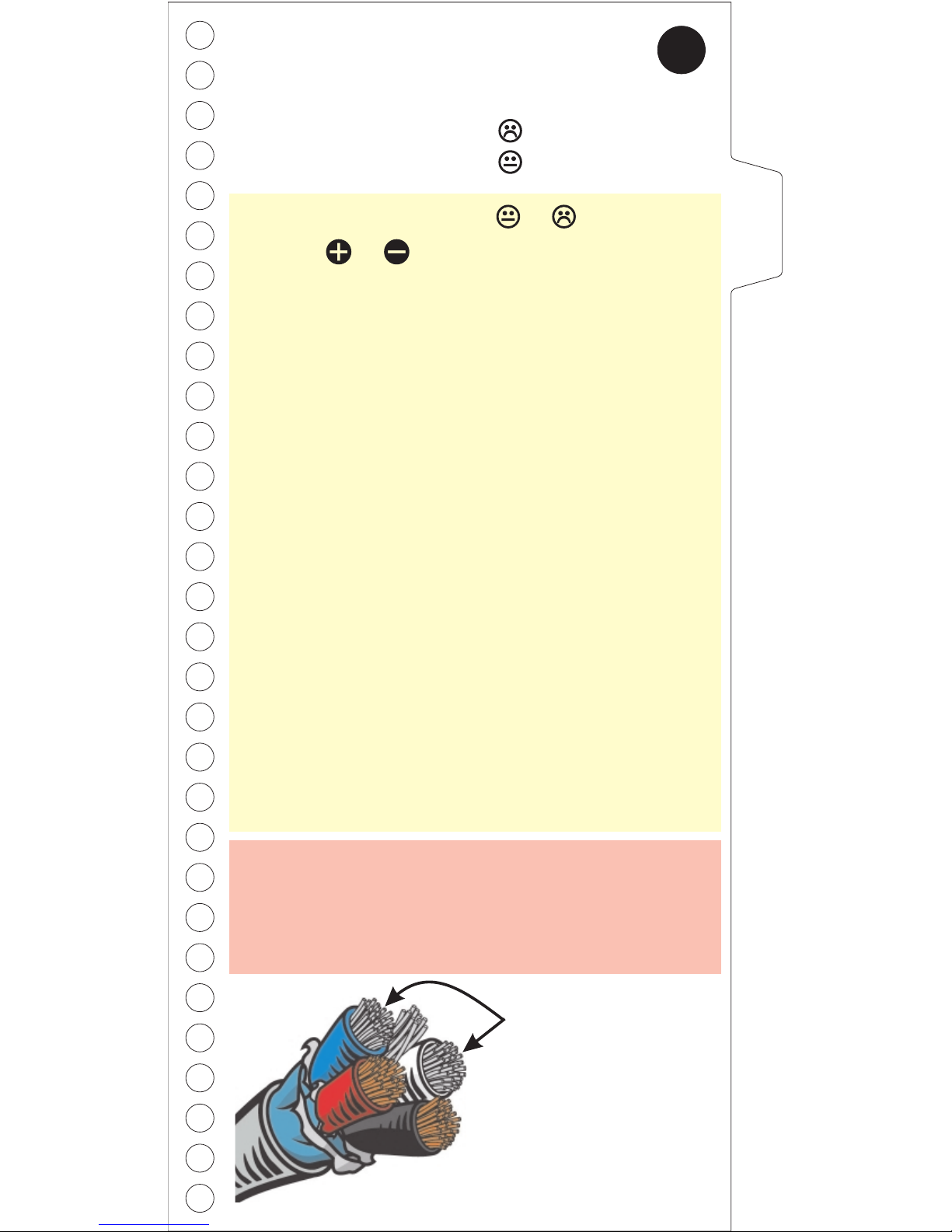
Bus Errors deal with
these two wires
(CANL & CANH)
!
!
Replace the device and/or cabling
Temporarily remove the device from the
network to see of the errors cease.
2
BUS ERRORS
7
Excessive cable lengths and faulty nodes can
cause errors in the transmissions of some/all
other nodes. Do not assume that the node(s) with
the highest error rate is faulty.
Thresholds:
Error Rate High Fault
Error Rate High Warn
15 /s
1/s
Page 8
Bus Traffic
NetMeter continuously monitors the CAN bit-stream for
message traffic. NetMeter reports Bus Traffic as either
network bandwidth consumed (including bandwidth
consumed by errors/retries) or bus frames per second.
Display
What it means
Current network or
node bandwidth
utilization.
Number of message
frames per second
on the network or
node.
Maximum network or
node bandwidth
recorded since
NetMeter was
connected or reset.
Minimum network or
node bandwidth
recorded since the
NetMeter was
plugged into the
network or reset.
x
1
x
2
x
3
x
4
x
5
Miinimum frame rate
(/S) on the network
or node since the
NetMeter was
plugged in or reset.
Maximum frame
rate(/S) on the
network or node
since the NetMeter
was plugged in or
reset.
%
250
/S
250
MIN
K
/S
250
MAX
K
K
/S
250
%
250
MAX
%
250
MIN
3
8
Node traffic measurements include only messages
transmitted by the device except Group 2 master/slave
traffic, where ALL traffic shows up on the slave MAC ID.
Page 9
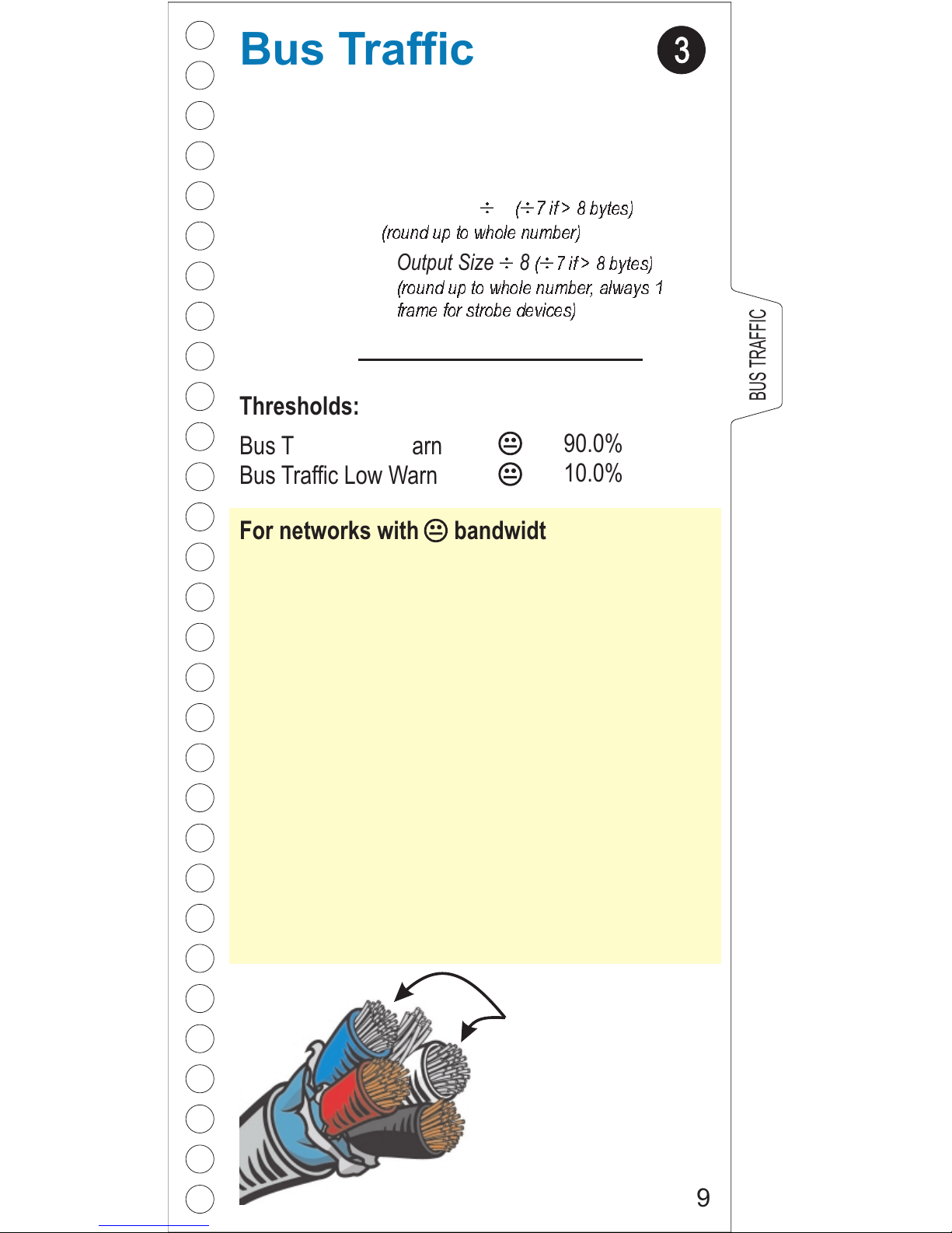
Bus Traffic of 0% for a single node means that the node
(MACID) has stopped communicating since the
NetMeter was plugged in or reset!
!
!
!
Check the scanner configuration.
Setting the scan interval (or inter-scan delay)
too short can cause device timeouts due to
bandwidth or node performance limitations.
Setting the scan interval (or inter-scan delay) too
long reduces system performance and makes
inefficient use of available bandwidth.
!
Check for Change-of-State devices consuming
excessive bandwidth (look for one or more
nodes with excessive bandwidth or a MAX
bandwidth much higher than average)
Note about frame rate: If you know the input and output
size (in bytes) for a polled or strobed device (see your
configuration or the device documentation) you can
determine the scan rate (per second) as follows:
Bus Traffic deals with
these two wires
(CANL & CANH)
Scan rate =
Frame Rate (from NetMeter)
Input Frames + Output Frames
Input Frames =
Output Frames =
Input Bytes 8
(round up to whole number)
¸¸
( 7 if > 8 bytes)
Output Size 8
(round up to whole number, always 1
frame for strobe devices)
¸¸
( 7 if > 8 bytes)
Bus Traffic
Thresholds:
Bus Traffic High Warn
Bus Traffic Low Warn
90.0%
10.0%
3
BUS TRAFFIC
9
For networks with bandwidth we suggest:
Page 10
Bus Power
NetMeter continuously monitors the DeviceNet bus
power quality.
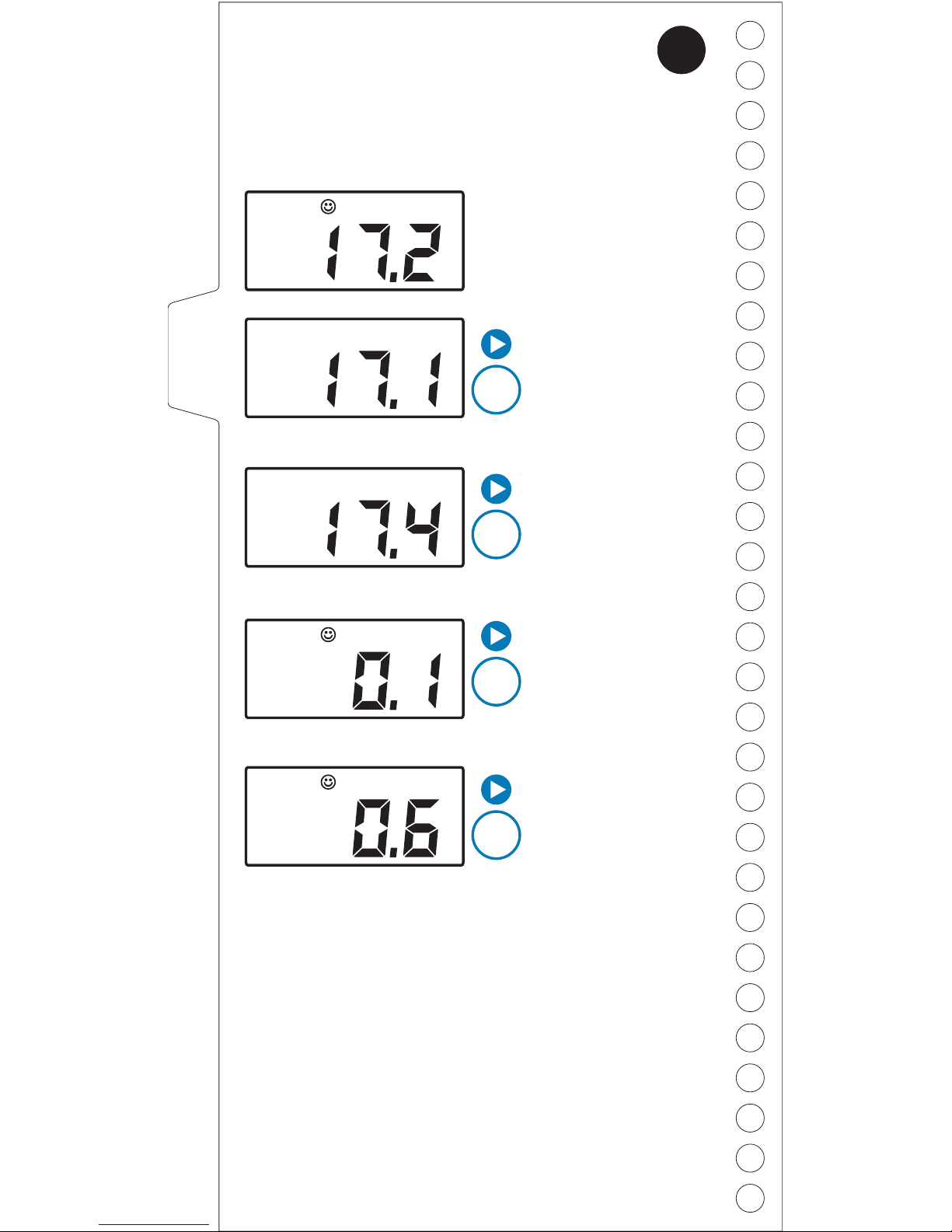
Display
What it means
Current network bus
voltage is 17.2V.
Minimum bus
voltage recorded
since NetMeter was
plugged in or reset is
17.1V.
Maximum peak-topeak (P-P) voltage
recorded since
NetMeter was
plugged in or reset is
0.6V.
Current peak-topeak (P-P) voltage
(transient or ripple)
is 0.1Vp-p.
Maximum bus
voltage recorded
since NetMeter was
plugged in or reset is
17.4V.
x
1
x
4
x
3
x
2
V
250
V
250
MIN
V
250
MAX
V
250
P-P
V
250
MAX
P-P
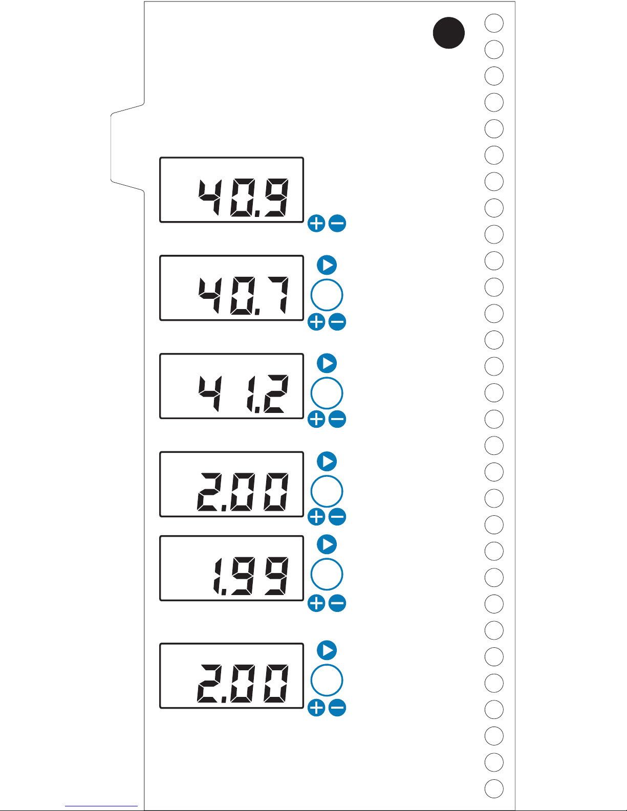
What’s a transient?
A transient is a short, temporary deviation of the bus
voltage level.
4
Every DeviceNet network has some level of bus power
transients, which is perfectly acceptable. Transients in
excess of 2V P-P can contribute to node failures and
communication errors in some cases and should be
investigated. Transients in excess of 10V P-P are an
indication of serious network problems..
10
Page 11
Bus Power measures
voltage levels on these
two wires (V+ / V-)
!
!
!
Check your power supply for proper installation
and correct output voltage under load.
Are your trunk/drop cables too long?
Is one or more of your devices drawing too
much current?
For bus power voltage levels we suggest:
!
!
!
Check for output devices (like contactors)
powered from the network (they shouldn’t be).
Check for network cables routed too close to
strong sources of interference
Check for aging network power supply with
output ripple increasing over time
For p-p (noise) levels we suggest:
Bus Power
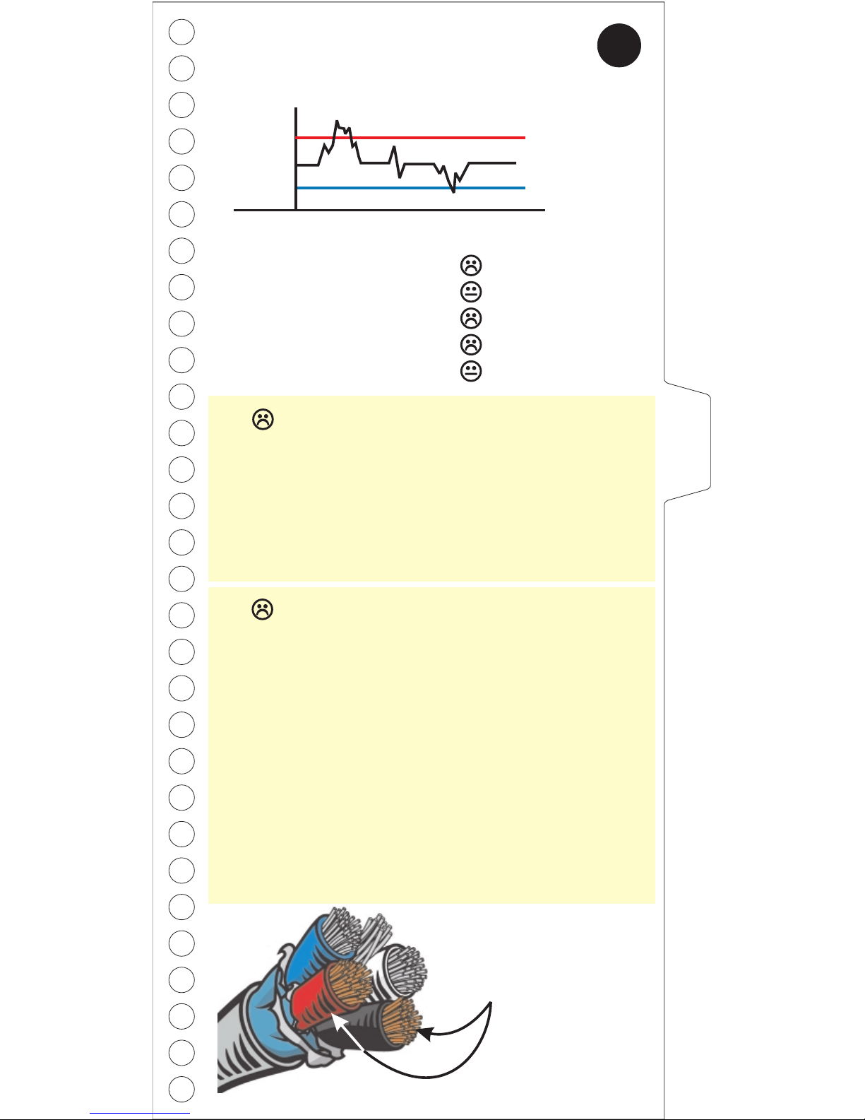
Examples of transients
25V
13V
Thresholds:
High Voltage Fault
Low Voltage Warning
Low Voltage Fault
High P-P Voltage Fault
High P-P Voltage Warning
25.0V
14.0V
13.0V
10.0V
2.0V
4
BUS POWER
11
!
If you suspect an intermittent cable or
connector, shake, bend or twist the suspected
cable and/or connector while watching the P-P
measurement for changes (up or down).
Page 12
Shield Voltage
NetMeter measures live, minimum, and maximum DC
shield voltage (between shield and V-).
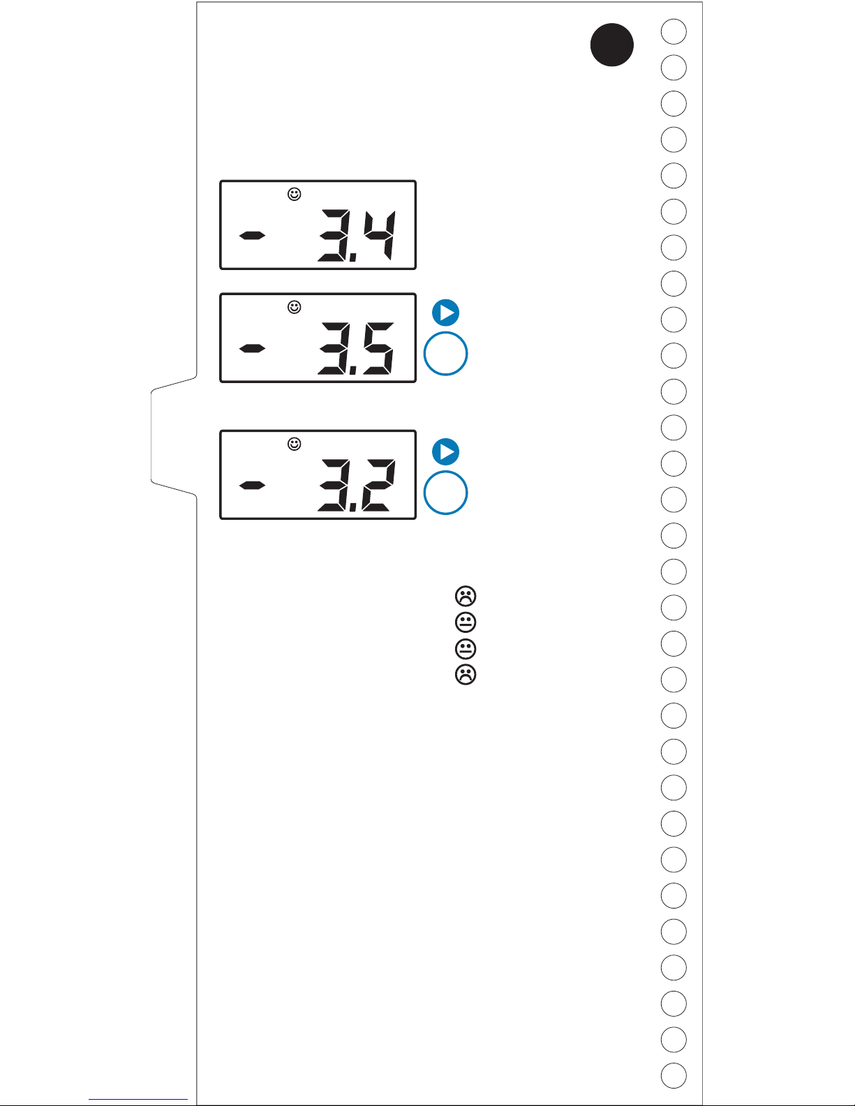
Display
What it means
Current shield
voltage is -3.4V.
The minimum shield
voltage recorded
since the NetMeter
was plugged in or
reset is -3.5V.
The maximum shield
voltage recorded
since the NetMeter
was plugged in or
reset is -3.2V.
x
1
x
2
V
250
V
250
MIN
V
250
MAX
5
12
Thresholds:
High Voltage Fault
High Voltage Warning
Low Voltage Warning
Low Voltage Fault
1.0V
0.3V
-4.0V
-5.0V
About DeviceNet Shield Votlage
The DeviceNet specification requires that the shield and
V- be connected together, and both to earth ground at
the power supply. This has the following effects:
A correctly connected shield has no current flow in it
and is at the same voltage (grounded power supply
V-) throughout the system.
Current flow in V- causes a voltage rise in VRising V- voltage causes an apparent negative shift in
the shield voltage when measured relative to V-
!
!
!
!
!
Since the maximum voltage drop in V- is 5V, the
negative shift in shield voltage is between -5V and 0V
Systems connected in accordance with the DeviceNet
installation guidelines (except flat media) have a
"normal" shield voltage between -5V and 0V
Page 13
Shield voltage
measures the
voltage on the shield
wire relative to V-
Shield Voltage
!
!
!
!
Make sure the Shield and V- are connected to
each other and to earth ground at the power
supply (very important)
Check for shorted or open shield wiring
Check that your shield wire is actually
grounded correctly (it’s so important you check
it twice!)
The NetMeter displays “OL” if the shield is not
connected (or if the voltage is high).
For shield voltage levels we suggest:
5
SHIELD
13
Important! Some industrial applications and some endusers employ different shield connection techniques to
meet specific requirements. In these cases the shield
voiltage will differ from that expected in "typical"
DeviceNet installations.
Semiconductor Fab Applications:
Disregard or shield voltage indications if
the shield is intentionally connected differently
than defined in the DeviceNet Specification.
Flat Media Applications:
Disregard or shield voltage indications in
flat media applications as flat media has no
shield. NetMeter should always display OL when
connected to a flat media system.
Important! DeviceNet Flat Media has no shield, and
shield voltage measurements are not relevant.
Page 14
CAN Primer
DeviceNet is based on the CAN protocol. A
fundamental understanding of CAN will help you
take full advantage of the NetMeter’s features and
significantly improve your ability to diagnose
network problems quickly.
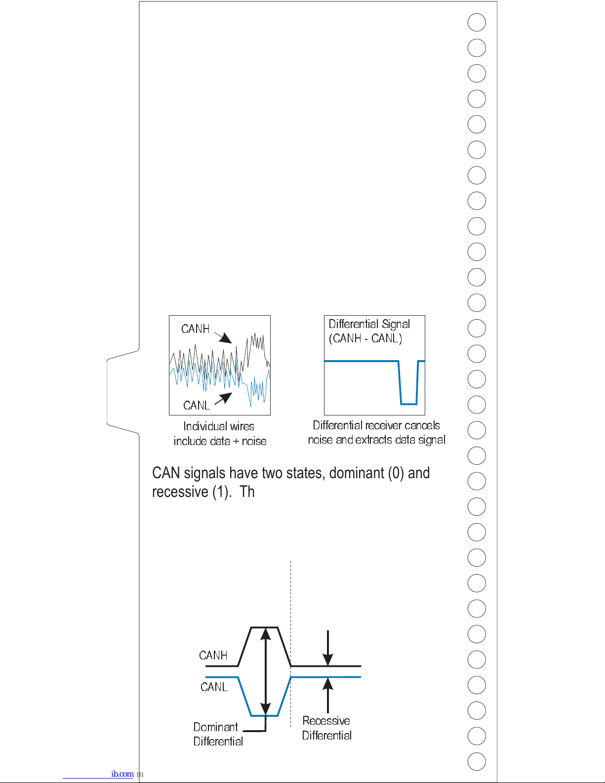
CAN messages are transmitted as a difference in
voltage between two separate wires, CANH
(white) and CANL (blue). Differential transmission
helps CAN and DeviceNet to operate well even
with high levels of external interference (ie from
sources like motors, welders, etc.) Here’s what
you might see if you captured CAN signals on an
oscilloscope:
Differential receiver cancels
noise and extracts data signal
CAN signals have two states, dominant (0) and
recessive (1). The transceiver in each DeviceNet
node determines whether a signal isa1ora0
based on the differential voltage between CANH
and CANL.
CANH
CANL
Dominant
(D)
Recessive
(R)
CANH
CANL
Dominant
Differential
Recessive
Differential
14
Individual wires
include data + noise
Differential Signal
(CANH - CANL)
Page 15
CAN Primer
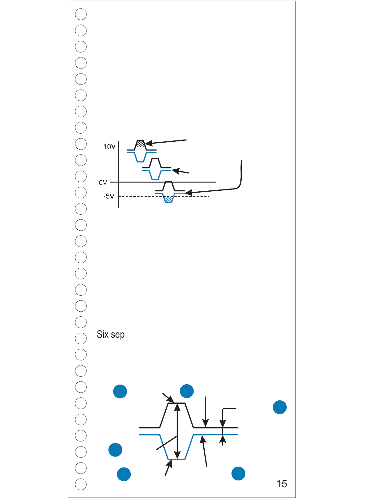
Because the transceiver subtracts the CANH and
CANL signals to determine the bit values, any
noise induced in the cable (the same noise is
induced in both wires) is cancelled. Transceiver
chips require CANH and CANL voltages to be
within specific limits otherwise a dominant (0)
might be misinterpreted as a recessive (1) or viceversa resulting in errors.
These out-of-range signals
could be misinterpreted
Good signal
DC common mode voltage (caused by voltage
drop in the cable, refer to page 16 and 17) is the
primary cause of the voltage shift illustrated
above. Noise induced in the data wires also
contributes to the voltage offset.
If the combination of DC common mode voltage
and induced noise causes the signal voltages to
exceed the transceivers capabilities, bit errors are
more likely to occur.
CANH,D
CANL,D
CANH,R
CANL,R
CANH/L
Diff V, D
CANH/L
Diff V, R
8
7
9
10
11
12
0V
-5V
10V
15
Six separate CAN voltage measurements are
essential to rapid troubleshooting. The NetMeter
accurately measures these voltages at the
following switch settings:
Page 16
Common Mode V
NetMeter measures the worst-case total Common Mode
Voltage for your network (including DC CMV and noise).
What is Common Mode Voltage?
Common Mode Voltage is an incidental voltage that is
common to both signal conductors in a differential
transmission system. CMV manifests itself as an shift in
signal voltage without any change in differential voltage.
Excessive CMV may cause signal voltages to exceed
the capabilities of transceiver chips, ultimately resulting
in communication errors.
The primary component of CMV is voltage drop in the
power conductors. The cable resistance causes the V+
voltage to drop from 24 VDC with increasing distance
from the power supply. Similarly, the V- voltage
increases proportionally from 0VDC at the power supply.
This offset results in each station having a slightly
different reference point (V-) which causes an apparent
shift in signal voltages from each node's point of view
(the signal voltages don't really change, but the
difference in V- makes it look that way).
Intermittent factors such as external interference,
variations in network load current and electrical noise
internal to nodes also contribute to CMV. Collectively,
these intermittent factors are called "noise".
Total CMV is critical to network health. NetMeter
measures total CMV over time and records the
maximum. To measure worst-case total CMV, leave the
NetMeter connected to the network for an appropriate
period of time (one machine cycle, one shift, one day).
Display
What it means
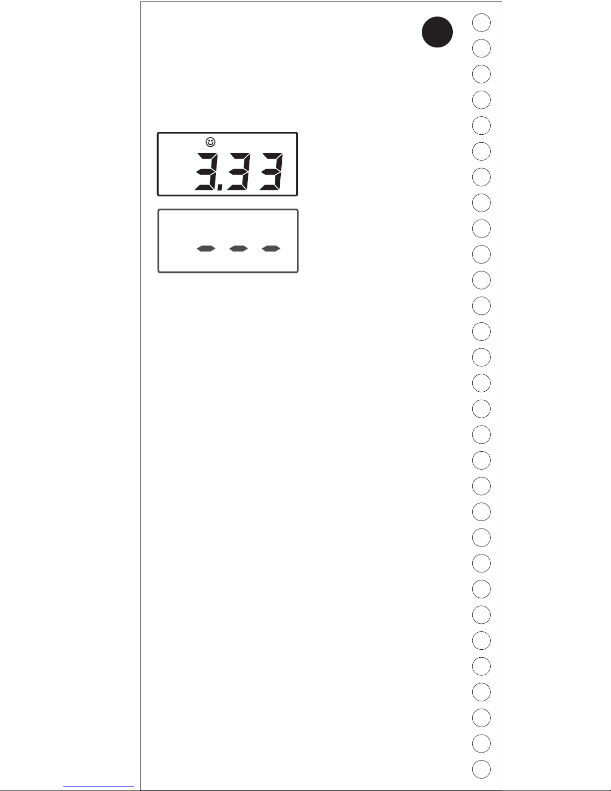
Worst-case total CMV
recorded since the
NetMeter was plugged in
or reset is 3.33V.
V
250
6
16
Common Mode Voltage
can not be determined
because there is no bus
activity.
Page 17
!
!
!
!
!
Check for devices that might be drawing more
current than you expect
Verify your network design with special
attention to cable length and load current
calculations
Move the power supply toward the middle of the
network, or toward the nodes that draw the
most current
Investigate adding another power supply to
reduce voltage offset in VHigh levels of external interference may require
you to reduce the DC CMV limit below the 5V
recommended in the DeviceNet Specification to
keep total CMV below 6.5V
!
!
!
NetMeter's CMV measurements are not affected by
where on the network you take the measurement.
DC CMV problems are typically caused when devices
draw more current than expected or when cable
resistance is higher than expected (too much cable)
or a combination of both.
CMV problems can be intermittent since few devices
have a constant load current.
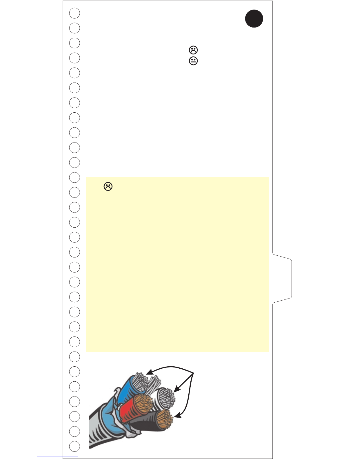
Common mode
voltage deals with
these three wires
(CANL, CANH,
and V-)
Common Mode V
Thresholds:
CMV High Fault
CMV High Warning
6.50V
5.00V
6
CMV
17
For CMV levels we suggest:
Notes About Common Mode Voltage (CMV)
Page 18
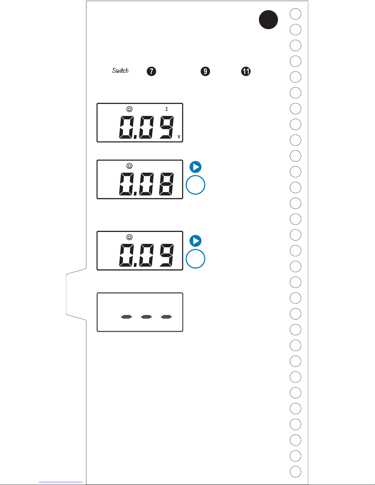
CANH/L Diff. V (R)
CANH/L differential (Recessive) shows you the
difference between CANH and CANL for recessive bits:
Why is this measurement important?
Data bits (0's and 1's) are transmitted as differences in
voltage between the CANH and CANL wires. The
differential voltage measurements are essentially a
measurement of "signal quality".
The recessive differential voltage is ideally zero, but
typically is +/- a few millivolts.
A recessive differential voltage that is not sufficiently
close to zero may be mis-interpreted by a transceiver as
a dominant bit - resulting in communication errors.
Display
What it means
Current CANH/L
recessive voltage
differential is 0.09V.
Minimum CANH/L
recessive voltage
differential since the
NetMeter was
plugged in or reset is
0.08V.
Maximum CANH/L
recessive voltage
differential since
NetMeter was
plugged in or reset is
0.09V.
x
1
x
2
CANH/L diff. V(R) = CANHV(R) - CANLV(R)
Switch
9 117
V
250
V
250
MIN
V
250
MAX
7
18
Recessive differential bus
voltage can not be
measured because the
bus is stuck dominant.
Page 19
!
!
!
Check for shorts and opens on the CANH and
CANL wires
Check for a missing or bad terminator (should
be two 120 ohm terminators from CANH to
CANL - one at each end of the network)
Disconnect nodes one at a time or temporarily
split the network to check for faulty transceivers
or cables.
What is “recessive?”
DeviceNet messages consist of 1’s and 0’s. The
recessive state of the bus (where the differential voltage
between CANH and CANL is close to zero) represents
the logical value 1 (opposite from what you might
expect). The bus is always in the recessive state except
when a node is transmitting.
NetMeter measures the difference between CANH and
CANL for recessive bits on the network, and if the
difference is not close to 0 volts, NetMeter indicates a
warning or a fault.
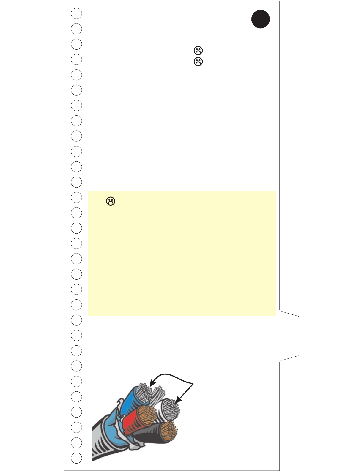
CANH/L Diff. V deals
with these two wires
(CANL & CANH)
CANH/L Diff. V (R)
Thresholds:
Diff R Voltage High Fault
Diff R Voltage Low Fault
0.08V
-0.18V
7
DIFFV(R)
19
For CANH/L differential recessive voltage
levels we suggest:
Page 20
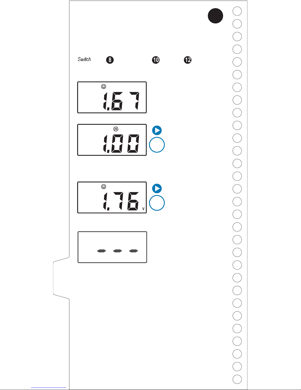
CANH/L Diff. V (D)
CANH/L differential shows you the difference between
CANH and CANL for dominant bits:
Display
What it means
Current CANH/L
dominant voltage
differential is 1.67V.
Minimum CANH/L
dominant voltage
differential since the
NetMeter was
plugged in or reset is
1.00V.
Maximum CANH/L
dominant voltage
differential since
NetMeter was
plugged in or reset is
1.76V.
x
1
x
2
CANH/L diff. V(D) = CANHV(D) - CANLV(D)
Switch
10 128
V
250
MAX
V
250
8
20
V
250
MIN
Dominant differential bus
voltage can not be
measured because there
is no bus activity.
Why is this measurement important?
See the description of "recessive" on page 18.
The dominant differential voltage is usually around 2V. A
lesser differential voltage may be mis-interpreted by a
transceiver as a recessive bit - causing bus errors.
At the beginning of each frame it is possible for several
nodes to transmit simultaneously resulting in a dominant
differential >3V. NetMeter accurately measures dominant
voltage by sampling only when one node is transmitting.
A measured dominant differential (single node
transmitting) larger than 3V is a clear indication of a
network problem.
Why is this measurement important?
Page 21
CANH/L Diff. V (D)
Thresholds:
Diff D Voltage High Fault
Diff D Voltage High Warning
Diff D Voltage Low Warning
Diff D Voltage Low Fault
3.00V
2.75V
1.45V
1.20V
CANH/L Diff. V deals
with these two wires
(CANL & CANH)
8
DIFFV(D)
21
What is “Dominant”?
DeviceNet messages consist of 1’s and 0’s. The
dominant state of the bus (where the differential voltage
between CANH and CANL is around 2V) represents the
logical value 0 (opposite from what you might expect).
The bus can only be in the dominant state when a node
is actively transmitting.
NetMeter measures the difference between CANH and
CANL for dominant bits on the network, and if the
difference is not within acceptable limits, NetMeter
indicates a warning or a fault.
!
!
!
Check for shorts and opens on the CANH and
CANL wires
Check for a missing, bad, or extra terminators
(should be two 120 ohm terminators from
CANH to CANL - one at each end of the
network !)
Disconnect nodes one at a time or temporarily
split the network to check for faulty transceivers
or cables.
and no more
For CANH/L differential dominant voltage
levels we suggest:
Page 22
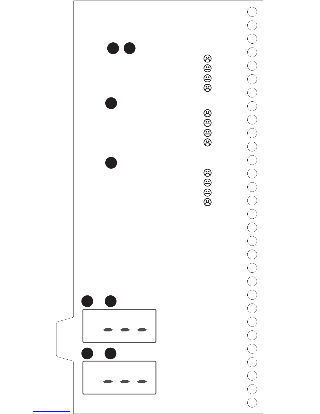
CAN Signal Thresholds
Thresholds:
Switch
CANH D Voltage High Fault
CANH D Voltage High Warning
CANH D Voltage Low Warning
CANH D Voltage Low Fault
10.00V
8.50V
-1.25V
-2.25V
10
Switch
CANL D Voltage High Fault
CANL D Voltage High Warning
CANL D Voltage Low Warning
CANL D Voltage Low Fault
7.75V
6.25V
-3.50V
-4.50V
12
Switch
CANH/L R Voltage High Fault
CANH/L R Voltage High Warning
CANH/L R Voltage Low Warning
CANH/L R Voltage Low Fault
8.50V
7.00V
-2.00V
-3.00V
9 11
DeviceNet messages consist of 1's and 0's, which are
represented as differences in voltage between the CANH
and CANL wires. However, if the absolute voltage of the
signal (measured to the V- wire at any node) is too high
or too low, bits may not be received correctly. NetMeter
measures each of the key CANH, CANL and Differential
voltages, and if the readings are too high or low,
NetMeter indicates a warning or fault.
22
Recessive bus voltage can
not be measured because
the bus is stuck dominant.
(or CAN wires are flipped)
Dominant bus voltage can
not be measured because
there is no bus activity.
10
9 11
12
&
&
Page 23

DeviceNet Glossary
Bandwidth:
CANbus:
Configuration:
Determinism:
Frame Rate:
MACID:
DeviceNet, like other serial networks,
supports a certain number of bits per second sent on the
wire. The actual network traffic is reported as a
percentage of the theoretical maximum, and is called %
Bandwidth. NetMeter's measurements include bandwidth
lost due to bus errors and retries but most other
diagnostic tools only include messages in
bandwidth calculations.
DeviceNet is based on a low-level network
standard known as CAN or CANbus. Other networks
that use CAN include CANOpen and SDS. Although
these networks are based on CAN, physical layer and
upper layer protocol differences limit the use of the
NetMeter with these networks.
Because DeviceNet networks allow you
to use devices in many different ways, each device must
be configured before it will work properly on a DeviceNet
network. For some devices, this is as simple as setting a
switch to select the MACID (node address) and baud
rate. Other devices require configuration from a PCbased software tool (Available from SST). Most
importantly, configuration means that before you replace
a device with another, identical device, you must
configure the replacement device properly.
Determinism is a measure of the
predictability of the performance of a system (including
but not limited to networks). Communication errors and
delays caused by high bandwidth utilization reduce
determinism, making the system less predictable in its
operation (less deterministic).
DeviceNet messages are sent in one or
more CAN message structures called Frames. Frame
Rate is the number of these structures sent in 1 second.
Since one DeviceNet message may require several CAN
frames, the frame rate is not necessarily the same as the
message rate.
Each device on a DeviceNet network has a
unique "Address", a number between 0 and 63. This
Address is known as the MACID or Node number.
successful
CANH / CANL
23
Page 24
DeviceNet Glossary
Noise:
P-P:
Ripple:
Terminator:
Transceiver:
Transient:
An undesirable intermittent voltage on a network
signal or power wire.
Peak to peak measurements of varying voltage
signals indicate the difference between the minimum and
maximum values within a specific interval.
A regular, repeated deviation from the mean
voltage of a power or signal conductor.
1) A resistor connected at the end of a
transmission line (network cable) to prevent signal
reflections caused by impedance mismatches.
DeviceNet requires two 120 ohm terminators, one at
each end of the network. DeviceNet terminating resistors
also define the recessive state of the network by
ensuring that CANH and CANL return to zero differential
after a dominant bit.
A transceiver is a circuit (typically a chip)
that converts digital bits to/from the differential voltages
on the network cable. Transceiver is a contraction of
mitter and re .
A temporary deviation from the mean voltage
of a power or signal conductor.
trans ceiver
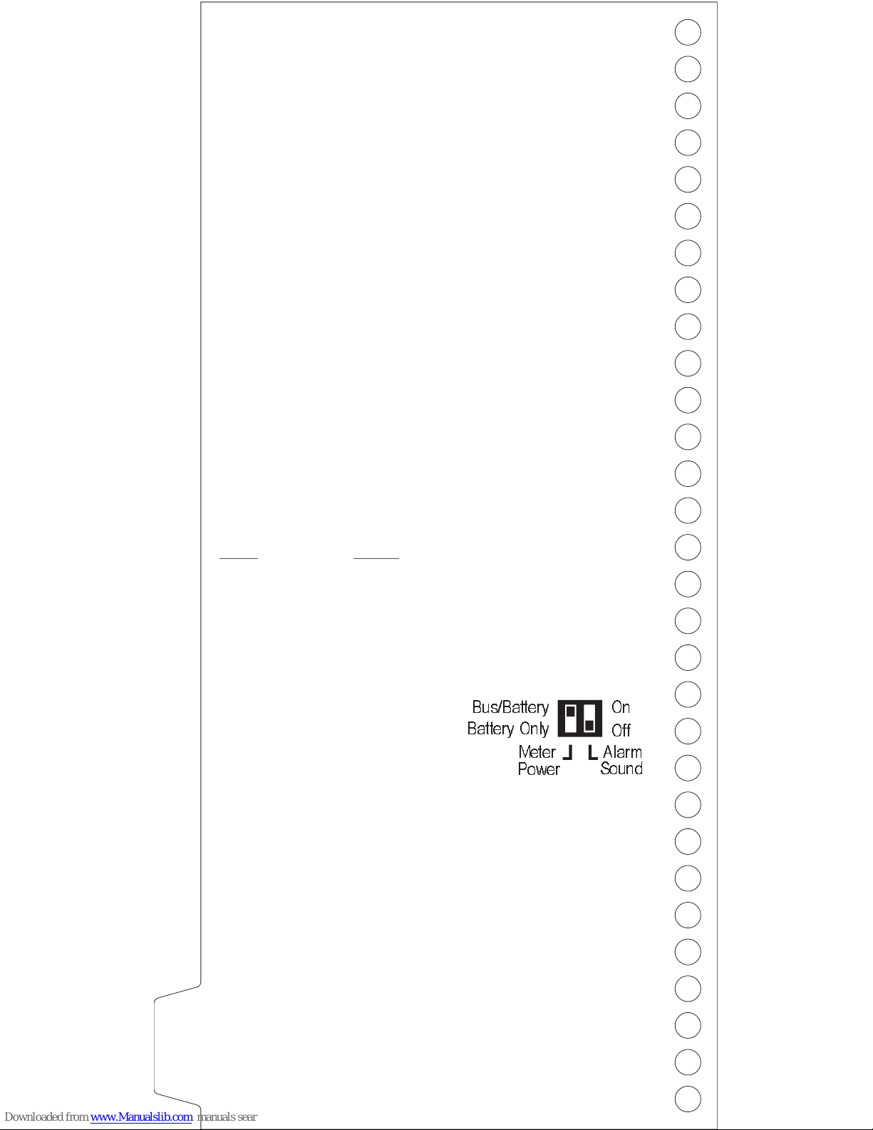
The NetMeter has two
configuration switches located
in the battery compartment.
The Meter Power switch (on left)
selects between bus/battery power (powered by bus
when available) and battery only power. Selecting
battery only power eliminates the possibility of
inadvertently contributing to common mode voltage
problems on extremely long networks but limits NetMeter
use to about 7 hours on fresh batteries..
The Alarm Sound switch (on right) enables and disables
the “beep on error/transient” feature. With this feature
enabled NetMeter beeps each time a bus error or
transient occurs when the selector switch is in the
corresponding position.
Switch Settings
24
Alarm
Sound
Meter
Bus/Battery
Battery Only
Power
Off
On
Page 25
Certifications
This device complies with Part 15 of the FCC Rules.
Operation is subject to the following two conditions: (1)
this device may not cause harmful interference and (2)
this device must accept any interference received,
including interference that may cause undesired
operation.
NOTE: This equipment has been tested and found to
comply with the limits for Class A digital device, pursuant
to Part 15 of the FCC Rules. These limits are designed
to provide reasonable protection against harmful
interference when the equipment is operated in a
commercial environment. This equipment generates,
uses, and can radiate radio frequency energy and, if not
installed and used in accordance with the instruction
manual, may cause harmful interference to radio
communications. Operation of this equipment in a
residential area is likely to cause harmful interference in
which case the user will be required to correct the
interference at his own expense.
Warning: Changes or modifications not expressly
approved by SST, a division of Woodhead Canada,
could void the user's authority to operate the equipment.
This Class (A) digital apparatus complies with Canadian
ICES-003.
FCC
Industry Canada
This device meets or exceeds the requirements of the
following standard(s):
UL3111-1 Can/CSA C22.2
CAT II 30V
25
LISTED
MEASURINGAND
TESTING EQUIPMENT
1WA4
Page 26
Certifications
Marking of this equipment with the symbol CE
indicates compliance with European Council
Directive 89/336/EEC - The EMC Directive as
amended by 92/31/EEC and 93/68/EEC.
To maintain compliance with the limits and
requirements of the EMC Directive it is required to use
quality interfacing cables and connectors when
connecting this device. Refer to the cable specifications
in the Hardware Guide for selection of cable types.
This device meets or exceeds the requirements of the
following standard:
EN 61326:1997 including amendment A1:1998 "Electrical equipment for measurement, control and
laboratory use - EMC requirements.”
This is a Class A product. In a domestic environment this
product may cause radio interference in which case the
user may be required to take adequate measures.
This equipment is neither designed for, nor intended for
operation in installations where it is subject to hazardous
voltages and/or hazardous currents.
Note:
Warning!
Caution!
Cables
The NetMeter is designed for use with the supplied
cables or the following Brad Harrison replacement
cables:
DND-21A-M010 DND-22A-M010
26
Page 27

Information & Support
Warranty
Care & Cleaning
For more information or technical support for the
NetMeter for DeviceNet or any other NetAlert product,
please contact your local Woodhead Connectivity
Distributor or one of our offices below:
SST/Woodhead Connectivity guarantees that all new
products are free from defects in material and
workmanship when applied in the manner for which they
were intended and according to SST’s published
information on proper installation. The Warranty period
for the NetAlert NetMeter for Devicenet is one year from
the date of shipment.
SST/Woodhead Connectivity will repair or replace, at our
option, all products returned freight prepaid, which prove
upon examination to be within the Warranty definitions
and time period.
The Warranty does not cover costs of installation,
removal, or damage to user property or any contingent
expenses or consequential damages. Maximum liability
of SST/Woodhead Connectivity is the cost of the
product(s).
If your NetMeter requires cleaning we recommend using
only a soft dry cloth. Solvents or water may enter the
enclosure with undesirable consequences.
SST division of Woodhead Canada Limited
Woodhead LP
Toll free: 877-427-0850
Direct: 847-272-7990
Woodhead Canada Limited
Direct: 905-624-6518
27
Page 28
Copyright © 2002 SST, a division of Woodhead Canada Limited
All rights reserved. No portion of this document may be reproduced in
any form without the prior written permission of Woodhead Canada
Limited.
NetAlert, NetMeter and SST are trademarks of Woodhead Industries,
Inc. All other trade names are trademarks or registered trademarks of
their respective companies.
SST strives to ensure accuracy in our documentation. However, due to
rapidly evolving products, on occasion software or hardware changes
may not have been reflected in the documentation. If you notice any
inaccuracies, please contact us.
Publication Revision: 1.2
Publication Date: February, 2002
SST, part of Woodhead Connectivity
50 Northland Road, Waterloo, Ontario
Canada N2V 1N3 Tel (519) 725-5136
www.myNetAlert.com
www.mySST.com
www.woodheadconnectivity.com
Document Info
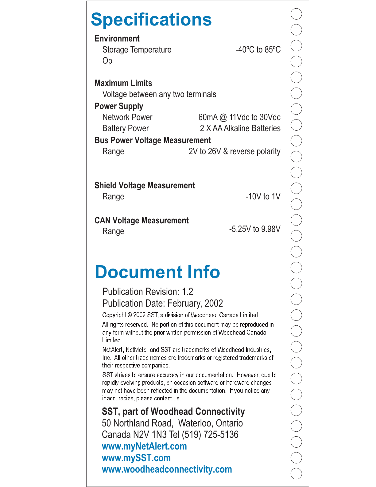
Specifications
Environment
Bus Power Voltage Measurement
Maximum Limits
Power Supply
Shield Voltage Measurement
CAN Voltage Measurement
Storage Temperature
Range
Voltage between any two terminals
Network Power
Battery Power
Range
Range
-40ºC to 85ºC
2V to 26V & reverse polarity
2 X AAAlkaline Batteries
60mA @ 11Vdc to 30Vdc
-10V to 1V
-5.25V to 9.98V
Operating Temperature
Calibrated Accuracy (DC)
Calibrated Accuracy
Calibrated Accuracy (signal)
0ºC to 40ºC
±30Vdc
0.5% ±1 count
0.5% ±1 count
0.5% ±2 counts±20mV
Humidity 5% to 90% (non-condensing)
28
Calibrated Accuracy (diff.) 1.0% ±4 counts±20mV
Calibrated Accuracy (P-P) 1.0% ±2 counts
 Loading...